EP4293263A1 - Manchette coupe-feu - Google Patents
Manchette coupe-feu Download PDFInfo
- Publication number
- EP4293263A1 EP4293263A1 EP22178804.5A EP22178804A EP4293263A1 EP 4293263 A1 EP4293263 A1 EP 4293263A1 EP 22178804 A EP22178804 A EP 22178804A EP 4293263 A1 EP4293263 A1 EP 4293263A1
- Authority
- EP
- European Patent Office
- Prior art keywords
- package
- band
- fire protection
- protection sleeve
- closure element
- Prior art date
- Legal status (The legal status is an assumption and is not a legal conclusion. Google has not performed a legal analysis and makes no representation as to the accuracy of the status listed.)
- Withdrawn
Links
Images



Classifications
-
- F—MECHANICAL ENGINEERING; LIGHTING; HEATING; WEAPONS; BLASTING
- F16—ENGINEERING ELEMENTS AND UNITS; GENERAL MEASURES FOR PRODUCING AND MAINTAINING EFFECTIVE FUNCTIONING OF MACHINES OR INSTALLATIONS; THERMAL INSULATION IN GENERAL
- F16L—PIPES; JOINTS OR FITTINGS FOR PIPES; SUPPORTS FOR PIPES, CABLES OR PROTECTIVE TUBING; MEANS FOR THERMAL INSULATION IN GENERAL
- F16L5/00—Devices for use where pipes, cables or protective tubing pass through walls or partitions
- F16L5/02—Sealing
- F16L5/04—Sealing to form a firebreak device
-
- A—HUMAN NECESSITIES
- A62—LIFE-SAVING; FIRE-FIGHTING
- A62C—FIRE-FIGHTING
- A62C2/00—Fire prevention or containment
- A62C2/06—Physical fire-barriers
- A62C2/065—Physical fire-barriers having as the main closure device materials, whose characteristics undergo an irreversible change under high temperatures, e.g. intumescent
Definitions
- the present invention relates to a fire protection sleeve for a pipe.
- Fire protection sleeves are used to provide sealing solutions for pipes, especially plastic pipes, that run through walls. The goal is to close the wall or ceiling breakthrough through which the pipe is routed in the event of a fire as soon as the melted or burned pipe no longer provides a seal.
- fire protection sleeves have an intumescent material. Intumescent materials have the property of expanding above a certain limit temperature. During expansion, the material foams and then carbonizes, providing a thermal insulating resistant layer. In the event of a fire, the wall or ceiling opening can be safely closed to prevent the flames from spreading through the wall or ceiling opening into adjacent rooms.
- endless sleeves for example, are known. Endless sleeves have a strip of intumescent material, which is cut to size by the user on site during installation depending on the diameter of the plastic pipe. On the one hand, this enables comparatively low manufacturing costs for the manufacturer, as they only have to produce an “endless belt”. On the other hand, endless sleeves require a comparatively high amount of work for the user to obtain a suitable sleeve depending on the diameter of the respective plastic pipe. The effort increases even further if the manufacturer does not provide a suitable holding structure, but rather the holding structure, which in the application is arranged on the outside of the intumescent material, is realized by a metal strip that is also cut to size by the user. The user then has to cut two tailor-made sections depending on the diameter of the plastic pipe. This often leads, for example in the case of untrained people Users, a relatively large amount of waste and therefore unwanted waste and also at high costs.
- prefabricated cuffs which have two sleeve elements which are placed around the pipe, are fastened to one another and each have a receiving space for the intumescent material.
- the sleeve elements can have holding structures by means of which the sleeve elements can be fixed to the wall.
- such sleeve elements are typically manufactured using punching and bending tools, with different punching and bending tools having to be provided by the manufacturer of the sleeve for different pipe diameters. For the manufacturer, the payback period for these tools is often very long, especially for pipe sizes that are not used frequently. The comparatively small quantities that can be sold on the market often do not justify the investment in such special and therefore cost-intensive tools.
- intumescent layer is usually arranged in multiple layers in the respective housing of the sleeve element.
- the increasing radius measured from the center of the plastic pipe, means that the different layers of the intumescent material must have different lengths. Nevertheless, the individual layers must be assembled into a package in order to be placed in the receiving space, which is typically carried out with a relatively large amount of manual work using additional materials such as adhesive tapes. This further increases the manufacturing effort.
- the invention is therefore based on the object of providing a fire protection sleeve by means of which the disadvantages of known fire protection sleeves can be eliminated or at least reduced.
- the respective wall or ceiling opening should be reliably closed if necessary.
- the fire protection sleeve according to the invention should preferably be accompanied by reduced effort for the user and the manufacturer.
- the fire protection sleeve should be particularly preferred for the user Except for the usual installation effort, there are no additional manufacturing costs.
- a fire protection sleeve for a pipe includes a band package which at least partially has an intumescent material. Furthermore, the fire protection sleeve includes a first and a second closure element. The first closure element is arranged at a first end of the band package and the second closure element is arranged at a second end of the band package opposite the first end. The first closure element and the second closure element can be closed with one another in such a way that the band package forms a substantially closed contour.
- the tape package has a package length between the first end and the second end of the tape package and is at least partially exposed along the package length.
- the fire protection sleeve designed in this way advantageously enables low manufacturing effort for the manufacturer and avoids any additional effort for the installer or user other than the usual installation work. Due to the closure elements arranged at the opposite ends of the bench package and the fact that the band package is at least partially exposed between the closure elements, the fire protection sleeve does not require complex molded parts, for which the manufacturer would have to provide costly punching or bending tools. In addition, the fact that the closure elements are arranged at the ends of the band package also provides cost-effective adaptability of the production in relation to different pipe diameters, since if necessary only the package length of the band package needs to be adjusted. However, the closure elements do not have to be modified. Furthermore, the band package does not have to be positioned in a complicated manner in a receiving space of a sleeve element.
- the manufacturer can produce the fire protection sleeve for different pipe diameters with relatively little effort, there is no need for any on-site adjustment measures by the installer or user with regard to the pipe diameter, with the exception of adjusting the package length. It is also advantageous for the installer that the closure elements also have the option of being fixed to one another, so that the fire protection sleeve forms the closed contour and can be placed around the pipe and arranged all around. This simplifies installation. Both the manufacturing and installation costs are therefore low.
- the band package preferably has several separate, parallel bands along the package length. Therefore, in the context of the present application, a band package is to be understood as an at least two-layer, generally also multi-layer arrangement of bands arranged in parallel. In particular, the band package can generally have between two and eight, preferably between four and seven, separate bands. The number of layers of the bands in the band package generally depends on the pipe diameter and therefore the size of the wall or ceiling opening.
- the bands generally mean separate strip-shaped components.
- the strip-shaped components at least partially comprise the intumescent material.
- the strip-shaped components are arranged essentially parallel (stacked) to one another along their longitudinal extension direction and width and typically have the same strip widths perpendicular to the longitudinal extension direction. Alternatively or cumulatively, the strip thicknesses of the strip-shaped components are also the same.
- the bands of the band package have different band lengths along their longitudinal direction.
- the longitudinal extension direction is oriented parallel to the circumference of the pipe.
- the closure elements have closure sections such that they can be fixed to one another by means of at least one positive connection.
- This ensures a closed contour of the fire protection sleeve around the pipe after installation.
- the connection can additionally or alternatively also be frictional.
- the connection can also be non-positive.
- securing components that cause spring force can also be provided in order to avoid loosening of the fixation.
- the package length is to be understood as meaning the length of a band of the plurality of bands of the band package which is maximum with respect to the different bands.
- the respective closure element at least partially encloses the band package at the respective end. Since the band package includes several bands, this means that each closure element encloses at least one band of the band package. In the present case, enclosing is to be understood as meaning that the closure element is fixed to the respective encased band, for example by means of a clamp connection or a hook connection.
- each closure element can also enclose several generally separate bands of the band package.
- first band ends of the bands of the band package defining the packet length are arranged flush relative to one another at the first end of the band packet and second band ends of the bands defining the packet length and opposite the first band ends are also arranged flush relative to one another at the second end of the band packet.
- each closure element encloses all generally separate straps of the strap package at the respective end. This enables a particularly stable design of the fire protection sleeve.
- first tape ends of the tapes of the tape package defining the package length are arranged flush relative to one another at the first end of the tape package and the second tape ends at the second end of the tape package are arranged offset from one another along the package length.
- a closure element encloses all generally separate bands of the band package at the first end.
- the complementary closure element in this embodiment only encloses a reduced number of the bands, in particular only one band, of the band package.
- the fire protection sleeve has an increased Flexibility, since at least some of the bands of the band package are only fixed at one end. This can be an advantage for complex and difficult installation situations.
- the band of the band package is enclosed by both closure elements, which, after installation, is arranged on the outside with respect to the radial distance to the pipe around which the fire protection sleeve is arranged.
- the outer band of the band package has to absorb all the intumescent forces of all bands of the band package in the event of a fire.
- the external band must be suitable in terms of its load-bearing capacity to force the intumescent material that expands in the event of a fire along the radial direction towards the center of the fire protection sleeve, so that the wall or ceiling opening provided for the pipe can be closed. Therefore, in this embodiment, at least the outer band of the band package can comprise a correspondingly designed carrier layer that provides sufficient strength.
- all tapes of the tape package can include such a carrier layer, which means that the production of different tape types of the tape package can be avoided.
- each closure element has at least one fastening device by means of which the fire protection sleeve can be fixed to an external receptacle.
- the fastening device can be set up so that the fire protection sleeve can be mounted on the wall, the ceiling, or the floor, which has the wall or ceiling opening for the pipe, which is to be sealed in the event of a fire.
- the fire protection sleeve can optionally have at least one mounting device that at least partially surrounds and supports the band package between the first end and the second end.
- the assembly device can be viewed as an additional stabilization device with which the generally separate bands of the band package are coupled to one another at points in the area of the assembly device.
- the assembly device can be moved along the length of the package.
- the needs-based positioning of the assembly device can be particularly advantageously ensured along the length of the package.
- the mounting device has at least one additional fastening device by means of which the fire protection sleeve can be fixed to the external receptacle.
- the assembly device can therefore also contribute to fixing the fire protection sleeve.
- the fixation is particularly advantageously ensured by the displaceable mounting device at different relative positions along the package length of the tape package.
- At least the closure elements but in particular also the mounting device, have a metal. This prevents these components from melting prematurely in the event of a fire.
- the band package 12 has a package thickness PD.
- the bands 14 of the band packet 12 are arranged parallel to one another along the packet thickness PD.
- the bands 14 of the band package 12 are at least partially exposed between the first end 18A and the second end 18B. This means that the bands 14 are at least partially unsupported. They are therefore at least partially enclosed by further components along the packet length PL.
- closure elements 16A, 16B have locking devices 22, by means of which they can be fixed to the band package 12.
- the coordinate system 24 schematically illustrates the orientation of the length L, the width B and the thickness D with respect to both the bands 14 and the band package 12.
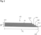
- FIG. 2 shows a simplified schematic representation of a band package12.
- the band package 12 in the present case comprises four bands 14A to 14D arranged in parallel.
- the individual bands 14A to 14D have different band lengths.
- the tape package length PL of the tape package 12 is determined by the length L of that tape 14A whose length L is maximum.
- the bands 14A to 14D are arranged flush with one another at the first end 18A of the band package 12. Due to the different tape lengths of the tapes 14A to 14B, the ends of the tapes 14A to 14D at the opposite second end 18B of the tape package 12 are arranged offset from one another, specifically along the longitudinal direction of the tape package 12.
- the bands 14A to 14D have at least a two-layer structure.
- a first layer of a tape acts as a carrier layer, whereas the second layer at least partially has an intumescent material.
- the locking devices 22 and the cover section 28 can advantageously bend back (bend open) in the event of a fire. This ensures that in the event of a fire, these components can be pushed back by the intumescence in order to give the fire protection sleeve 10 more space to expand.
- the closure element 16 further has a closure section 32, which can cooperate with a corresponding closure section 32 of a further closure element 16.
- the closure sections 32 can cooperate in such a way that an at least positive fixation of the closure elements 16 to one another is ensured, thereby ensuring a closed contour of the fire protection sleeve 10.
- the closure sections 32 therefore ensure easy installation of the fire protection sleeve 10 as they can be opened to provide the possibility of positioning the fire protection sleeve 10 around the pipe.
- the closure sections 32 can then cooperate and ensure that the fire protection sleeve 10 is fixed with respect to the pipe.
- the fastening device 20 comprises an elongated hole 33 in order to simplify the positioning of the closure element 16 on the external receptacle.
- the closure element 16 is made of a metal material.
- the closure element 16 does not have a complex geometry, so that cost-intensive punching and bending tools can be avoided during production.
- the closure element 16 is also for Different fire protection sleeves 10 are suitable depending on the respective pipe diameter. Therefore, only one type of closure element 16 needs to be produced.
- the closure element 16 is universal in pipe size.
- Figure 4 shows a simplified schematic representation of a fire protection sleeve 12 according to a further embodiment. Only differences from the previous embodiment will be discussed here.
- the first closure element 16A is arranged at a first end 18A of the band package 12, the bands 14 of which are arranged flush with one another at this first end 18A.
- the second closure element 16B is arranged at the second end 18B of the band package 12, the bands 14 of which end offset from one another at this second end 18B.
- the different band lengths of the bands 14 of the band package 12 mean that no additional gaps arise in the installation situation of the fire protection sleeve 10.
- the offset between the bands 14 along the longitudinal direction of the band package 12 in the area of the second end 18B of the band package 12 is selected such that it corresponds to the respective difference in length between adjacent bands 14, which in the installation situation is due to the different radial distances to the center of the fire protection sleeve 10 are caused.
- the mounting device 36 has two clamping sections 38A, 38B arranged in pairs.
- the band package 12 lies against the contact surface 40 of the mounting device 36 and the clamping sections 38A, 38B surround the tape package 12.
- the distance between the clamping sections 38A, 38B and the contact surface 40 therefore corresponds to the package thickness PD.
- the mounting device 36 has a third clamping section 42, which can be bent at a fold line 44 in order to be arranged on the opposite side relative to the contact surface 40 with respect to the then enclosed band package 12.
- the band package 12 is then framed by the mounting device 36.
- Figure 6 shows a simplified schematic representation of a fire protection sleeve 10 according to a further embodiment. Only differences from the previous embodiments will be discussed here.
- the assembly device 36 provides an additional coupling of the bands 14 of the band packet to one another in a coupling area 46 of the band package 12. This simplifies the assembly of the fire protection sleeve 10, because the spaces 13 are therefore limited perpendicular to the longitudinal direction and the width of the band package 12.
- the mounting device 36 can be displaced along the longitudinal direction of the band package 12, which is indicated here by the arrow 48. The displaceability makes the assembly of the fire protection sleeve 10 even easier, since the assembly device 36 can be positioned as required.
- the fire protection sleeve 10 can also have additional mounting devices 36.
- Figure 7 shows a simplified schematic representation of a fire protection sleeve 10 according to a further embodiment. Only differences from the previous embodiment will be discussed here.
- the fire protection sleeve 10 now also has a plastic layer 50.
- the plastic layer 50 comprises a foam 52 and, depending on the installation situation, is arranged along the radial direction of the fire protection sleeve 10 on the inside relative to the band package 12 and parallel thereto.
- the foam 52 of the plastic layer 50 is compressible and can cause frictional forces with respect to the pipe around which the fire protection sleeve 10 is to be installed.
- the frictional forces prevent the fire protection sleeve 10 from slipping unintentionally along the pipe before the fire protection sleeve 10 is fixed to an external receptacle, for example by means of fastening devices 20, 34. This simplifies assembly.
Landscapes
- Engineering & Computer Science (AREA)
- General Engineering & Computer Science (AREA)
- Health & Medical Sciences (AREA)
- Public Health (AREA)
- Business, Economics & Management (AREA)
- Emergency Management (AREA)
- Mechanical Engineering (AREA)
- Clamps And Clips (AREA)
Priority Applications (5)
| Application Number | Priority Date | Filing Date | Title |
|---|---|---|---|
| EP22178804.5A EP4293263A1 (fr) | 2022-06-14 | 2022-06-14 | Manchette coupe-feu |
| EP23730071.0A EP4540544A1 (fr) | 2022-06-14 | 2023-05-31 | Manchon de protection contre l'incendie |
| US18/873,028 US20250354630A1 (en) | 2022-06-14 | 2023-05-31 | Fire protection collar |
| CA3249525A CA3249525A1 (fr) | 2022-06-14 | 2023-05-31 | Collier de protection contre les incendies |
| PCT/EP2023/064522 WO2023241914A1 (fr) | 2022-06-14 | 2023-05-31 | Manchon de protection contre l'incendie |
Applications Claiming Priority (1)
| Application Number | Priority Date | Filing Date | Title |
|---|---|---|---|
| EP22178804.5A EP4293263A1 (fr) | 2022-06-14 | 2022-06-14 | Manchette coupe-feu |
Publications (1)
| Publication Number | Publication Date |
|---|---|
| EP4293263A1 true EP4293263A1 (fr) | 2023-12-20 |
Family
ID=82058417
Family Applications (2)
| Application Number | Title | Priority Date | Filing Date |
|---|---|---|---|
| EP22178804.5A Withdrawn EP4293263A1 (fr) | 2022-06-14 | 2022-06-14 | Manchette coupe-feu |
| EP23730071.0A Pending EP4540544A1 (fr) | 2022-06-14 | 2023-05-31 | Manchon de protection contre l'incendie |
Family Applications After (1)
| Application Number | Title | Priority Date | Filing Date |
|---|---|---|---|
| EP23730071.0A Pending EP4540544A1 (fr) | 2022-06-14 | 2023-05-31 | Manchon de protection contre l'incendie |
Country Status (4)
| Country | Link |
|---|---|
| US (1) | US20250354630A1 (fr) |
| EP (2) | EP4293263A1 (fr) |
| CA (1) | CA3249525A1 (fr) |
| WO (1) | WO2023241914A1 (fr) |
Citations (5)
| Publication number | Priority date | Publication date | Assignee | Title |
|---|---|---|---|---|
| US5103609A (en) * | 1990-11-15 | 1992-04-14 | Minnesota Mining & Manufacturing Company | Intumescable fire stop device |
| US5634304A (en) * | 1993-12-15 | 1997-06-03 | Sakno; Michael P. | Water impervious intumescent firestop collapsing conduit |
| DE19852120C2 (de) * | 1998-08-19 | 2002-12-12 | Friatec Ag | Intumeszierende Brandschutzvorrichtung zum Abschotten von durch Wände oder Decken durchgeführten Rohren |
| US9638225B2 (en) * | 2012-09-26 | 2017-05-02 | Hilti Aktiengesellschaft | Closure element for a fire-protection sleeve |
| EP3477174B1 (fr) * | 2017-10-13 | 2021-07-21 | Rolf Kuhn GmbH | Manchette de protection contre l'incendie ainsi que logement correspondant et traversée de paroi ou de plafond comportant ladite manchette de protection contre l'incendie |
Family Cites Families (3)
| Publication number | Priority date | Publication date | Assignee | Title |
|---|---|---|---|---|
| US7596914B2 (en) * | 2005-12-15 | 2009-10-06 | Specified Technologies, Inc. | Universal firestopping collar assembly |
| US10975989B2 (en) * | 2015-06-19 | 2021-04-13 | Rockwool International A/S | Intumescent fire sleeve, coil of several intumescent fire sleeves and method for installation of an intumescent fire sleeve |
| EP3232105A1 (fr) * | 2016-04-12 | 2017-10-18 | HILTI Aktiengesellschaft | Procede de fabrication d'un module pour un passage de ligne, module et procede de fabrication d'un passage de ligne |
-
2022
- 2022-06-14 EP EP22178804.5A patent/EP4293263A1/fr not_active Withdrawn
-
2023
- 2023-05-31 CA CA3249525A patent/CA3249525A1/fr active Pending
- 2023-05-31 WO PCT/EP2023/064522 patent/WO2023241914A1/fr not_active Ceased
- 2023-05-31 EP EP23730071.0A patent/EP4540544A1/fr active Pending
- 2023-05-31 US US18/873,028 patent/US20250354630A1/en active Pending
Patent Citations (5)
| Publication number | Priority date | Publication date | Assignee | Title |
|---|---|---|---|---|
| US5103609A (en) * | 1990-11-15 | 1992-04-14 | Minnesota Mining & Manufacturing Company | Intumescable fire stop device |
| US5634304A (en) * | 1993-12-15 | 1997-06-03 | Sakno; Michael P. | Water impervious intumescent firestop collapsing conduit |
| DE19852120C2 (de) * | 1998-08-19 | 2002-12-12 | Friatec Ag | Intumeszierende Brandschutzvorrichtung zum Abschotten von durch Wände oder Decken durchgeführten Rohren |
| US9638225B2 (en) * | 2012-09-26 | 2017-05-02 | Hilti Aktiengesellschaft | Closure element for a fire-protection sleeve |
| EP3477174B1 (fr) * | 2017-10-13 | 2021-07-21 | Rolf Kuhn GmbH | Manchette de protection contre l'incendie ainsi que logement correspondant et traversée de paroi ou de plafond comportant ladite manchette de protection contre l'incendie |
Also Published As
| Publication number | Publication date |
|---|---|
| EP4540544A1 (fr) | 2025-04-23 |
| US20250354630A1 (en) | 2025-11-20 |
| WO2023241914A1 (fr) | 2023-12-21 |
| CA3249525A1 (fr) | 2025-03-17 |
Similar Documents
| Publication | Publication Date | Title |
|---|---|---|
| DE102006020407B3 (de) | Schelle zum Befestigen eines rohr- oder schlauchförmigen Gegenstandes | |
| EP0675308B1 (fr) | Manchon de tuyaux | |
| DE2112591C2 (de) | Aufweitbare Befestigungs- oder Verankerungsvorrichtung | |
| DE19852120C2 (de) | Intumeszierende Brandschutzvorrichtung zum Abschotten von durch Wände oder Decken durchgeführten Rohren | |
| DE102012216562C5 (de) | Brandschutzsystem bei Übergang auf Kunststoffrohr, und Verwendung einer Brandschutzvorrichtung | |
| EP0982522A2 (fr) | Dispositif coupe-feu | |
| DE2809819C2 (fr) | ||
| CH635172A5 (de) | Befestigungselement aus metall fuer platten oder hohlwaende. | |
| DE69712819T2 (de) | Haltevorrichtung für elektrische Verbindungsanordnung zum Einschuben durch Decken | |
| EP0404726A2 (fr) | Dispositif pour la connexion de rails en forme de C, en particulier rails de montage | |
| EP2261544A2 (fr) | Anneau de fixation | |
| DE3631183A1 (de) | Energiefuehrungsschlauch | |
| WO2023241914A1 (fr) | Manchon de protection contre l'incendie | |
| EP1790895B1 (fr) | Passage traversant un mur ou un plafond | |
| EP2660403B1 (fr) | Support pour matière isolante | |
| EP3443250B1 (fr) | Procede de fabrication d'un module pour un passage de ligne, module et procede de fabrication d'un passage de ligne | |
| AT512189B1 (de) | Brandschutzmanschette | |
| EP3894730B1 (fr) | Segment de manchon ignifuge et manchon ignifuge | |
| DE8701832U1 (de) | Scharnierelement | |
| EP2030652A2 (fr) | Traversée de cloison à structure modulaire | |
| EP4293264A1 (fr) | Manchon sans fin pour un tube | |
| DE202007008901U1 (de) | Profilverbinder und Verkleidung | |
| EP0388521B1 (fr) | Isolation thermique pour tuyaux ou vases | |
| DE4408339C2 (de) | Fassadendämmstoffdübel aus Metall | |
| DE102007047367B4 (de) | Kabelabschottung mit modularem Aufbau |
Legal Events
| Date | Code | Title | Description |
|---|---|---|---|
| PUAI | Public reference made under article 153(3) epc to a published international application that has entered the european phase |
Free format text: ORIGINAL CODE: 0009012 |
|
| STAA | Information on the status of an ep patent application or granted ep patent |
Free format text: STATUS: THE APPLICATION HAS BEEN PUBLISHED |
|
| AK | Designated contracting states |
Kind code of ref document: A1 Designated state(s): AL AT BE BG CH CY CZ DE DK EE ES FI FR GB GR HR HU IE IS IT LI LT LU LV MC MK MT NL NO PL PT RO RS SE SI SK SM TR |
|
| STAA | Information on the status of an ep patent application or granted ep patent |
Free format text: STATUS: THE APPLICATION IS DEEMED TO BE WITHDRAWN |
|
| 18D | Application deemed to be withdrawn |
Effective date: 20240621 |