EP4293324A1 - Procédé de détermination d'une pression de fluide dans un réseau d'alimentation en fluide et compteur de fluide à ultrasons - Google Patents
Procédé de détermination d'une pression de fluide dans un réseau d'alimentation en fluide et compteur de fluide à ultrasons Download PDFInfo
- Publication number
- EP4293324A1 EP4293324A1 EP23176653.6A EP23176653A EP4293324A1 EP 4293324 A1 EP4293324 A1 EP 4293324A1 EP 23176653 A EP23176653 A EP 23176653A EP 4293324 A1 EP4293324 A1 EP 4293324A1
- Authority
- EP
- European Patent Office
- Prior art keywords
- ultrasonic
- fluid
- change
- transducer
- measuring section
- Prior art date
- Legal status (The legal status is an assumption and is not a legal conclusion. Google has not performed a legal analysis and makes no representation as to the accuracy of the status listed.)
- Pending
Links
Images


Classifications
-
- G—PHYSICS
- G01—MEASURING; TESTING
- G01F—MEASURING VOLUME, VOLUME FLOW, MASS FLOW OR LIQUID LEVEL; METERING BY VOLUME
- G01F1/00—Measuring the volume flow or mass flow of fluid or fluent solid material wherein the fluid passes through a meter in a continuous flow
- G01F1/66—Measuring the volume flow or mass flow of fluid or fluent solid material wherein the fluid passes through a meter in a continuous flow by measuring frequency, phase shift or propagation time of electromagnetic or other waves, e.g. using ultrasonic flowmeters
- G01F1/662—Constructional details
-
- G—PHYSICS
- G01—MEASURING; TESTING
- G01F—MEASURING VOLUME, VOLUME FLOW, MASS FLOW OR LIQUID LEVEL; METERING BY VOLUME
- G01F1/00—Measuring the volume flow or mass flow of fluid or fluent solid material wherein the fluid passes through a meter in a continuous flow
- G01F1/66—Measuring the volume flow or mass flow of fluid or fluent solid material wherein the fluid passes through a meter in a continuous flow by measuring frequency, phase shift or propagation time of electromagnetic or other waves, e.g. using ultrasonic flowmeters
- G01F1/667—Arrangements of transducers for ultrasonic flowmeters; Circuits for operating ultrasonic flowmeters
-
- G—PHYSICS
- G01—MEASURING; TESTING
- G01F—MEASURING VOLUME, VOLUME FLOW, MASS FLOW OR LIQUID LEVEL; METERING BY VOLUME
- G01F15/00—Details of, or accessories for, apparatus of groups G01F1/00 - G01F13/00 insofar as such details or appliances are not adapted to particular types of such apparatus
- G01F15/02—Compensating or correcting for variations in pressure, density or temperature
-
- G—PHYSICS
- G01—MEASURING; TESTING
- G01F—MEASURING VOLUME, VOLUME FLOW, MASS FLOW OR LIQUID LEVEL; METERING BY VOLUME
- G01F15/00—Details of, or accessories for, apparatus of groups G01F1/00 - G01F13/00 insofar as such details or appliances are not adapted to particular types of such apparatus
- G01F15/14—Casings, e.g. of special material
-
- G—PHYSICS
- G01—MEASURING; TESTING
- G01L—MEASURING FORCE, STRESS, TORQUE, WORK, MECHANICAL POWER, MECHANICAL EFFICIENCY, OR FLUID PRESSURE
- G01L11/00—Measuring steady or quasi-steady pressure of a fluid or a fluent solid material by means not provided for in group G01L7/00 or G01L9/00
- G01L11/04—Measuring steady or quasi-steady pressure of a fluid or a fluent solid material by means not provided for in group G01L7/00 or G01L9/00 by acoustic means
- G01L11/06—Ultrasonic means
Definitions
- the present invention relates to a method for determining a fluid pressure in a fluid supply network for fluid according to the preamble of claim 1 and an ultrasonic fluid meter for installation in a fluid supply network according to the preamble of claim 16.
- Ultrasonic fluid meters are commonly used to determine fluid consumption levels in a fluid supply network.
- the fluid supply network can consist of a plurality of piping systems.
- Ultrasonic fluid meters are generally used to determine flow, volume or heat quantity and/or to determine the pressure of fluids, such as. B. water, used.
- ultrasonic fluid meters usually have a connection housing with an inlet and an outlet. By means of the connection housing, the ultrasonic fluid meter can be installed in a pipeline system of a fluid supply network, such as. B. a drinking water supply can be installed.
- the flow direction of the fluid within the ultrasonic fluid meter can be unchanged from inlet to outlet or can also change depending on the design of the ultrasonic fluid meter.
- ultrasonic fluid meters can also be used to determine the fluid pressure.
- an ultrasonic fluid meter is based on the use of ultrasonic transducers, in particular on a piezoelectric basis, which are attached in the area of the connection housing of the ultrasonic fluid meter.
- Two ultrasonic transducers always form a pair of ultrasonic transducers, with each other between There is an ultrasonic measuring section between the two ultrasonic transducers of the ultrasonic transducer pair.
- Ultrasonic signals, so-called ultrasonic bursts which are sent and received by the ultrasonic transducers, run along the ultrasonic measuring path.
- the flow and/or volume of a medium flowing through can be determined using an ultrasonic meter based on a transit time difference measurement of the ultrasonic signals.
- the transit time difference is determined by first transmitting an ultrasonic signal from a first ultrasonic transducer to a second ultrasonic transducer along the ultrasonic measuring section and z. B. is sent obliquely in the direction of flow. An ultrasonic signal is then sent in opposite directions from the second ultrasonic transducer along the ultrasonic measuring section, e.g. B. also sent obliquely to the flow direction to the first ultrasonic transducer.
- the transmission of the ultrasonic signal from one ultrasonic transducer to the other ultrasonic transducer along the ultrasonic measuring section occurs faster in the direction of flow of the medium than in the opposite direction of the flow of the medium.
- This time difference in the transmission duration of the two ultrasonic signals is referred to as the transit time difference of the ultrasonic signals. Based on this difference in transit time and the previously known dimension of the ultrasonic fluid meter or the ultrasonic measuring section, the flow or the volume of the medium flowing through can be determined independently of the speed of sound in the medium.
- the ultrasonic velocity in the fluid can also be determined based on the individual ultrasound transit times or a sum. This depends on the temperature and the fluid pressure. If the temperature is known and/or constant or the temperature is measured, the fluid pressure can be determined at a known ultrasonic speed. However, since the ultrasonic speed only changes slightly when the pressure changes, even small measurement deviations when measuring the ultrasonic transit time or ultrasonic transit times lead to large deviations when determining the pressure.
- the DE 10 2012 022 376 A1 discloses a method for determining the pressure of a fluid in a container, wherein a property of the fluid influenced by the pressure of the fluid or of an element in the container subjected to the pressure of the fluid is determined by means of an acoustic wave in the fluid and wherein from the determined Property of the pressure is determined. A correction of measurement deviations is not disclosed, so that the fluid pressure can only be determined with limited accuracy.
- the object of the present invention is to provide a method for determining a fluid pressure in a fluid supply network for fluid and an ultrasonic meter in which a fluid pressure is determined using compensation. This is intended to increase the accuracy of the pressure determination.
- a particular advantage of the invention is that the fluid pressure can be determined much more precisely through mathematical compensation.
- an ultrasonic signal can be emitted by the first ultrasonic transducer, which is received by the second ultrasonic transducer, the ultrasonic transit time being determined.
- An ultrasonic signal can be emitted by the second ultrasonic transducer and received by the first ultrasonic transducer, the ultrasonic transit time also being determined.
- the flow velocity and/or a variable proportional to the flow velocity, in particular a flow rate can be determined from the measured ultrasonic transit times and/or from the difference of the measured ultrasonic transit times and/or the difference of the reciprocals of the measured ultrasonic transit times.
- the formation of the difference in the measured ultrasonic transit times and/or the difference in the reciprocals of the measured ultrasonic transit times enables the flow velocity or a variable proportional to the flow velocity, in particular the flow, to be determined independently of the ultrasonic velocity.
- the fluid pressure can be calculated from the measured ultrasonic transit times and/or from a transit time difference of the measured ultrasonic transit times and/or from a difference of the reciprocals of the measured ultrasonic transit times and/or from a transit time sum of the measured ultrasonic transit times and/or from a sum of the reciprocals of the measured ultrasonic transit times and/or from an average of the measured ultrasonic transit times.
- the ultrasonic speed can be determined via the sum of the measured ultrasonic transit times and/or the sum of the reciprocals of the measured ultrasonic transit times or via the average value of the measured ultrasonic transit times, regardless of the flow velocity or a variable proportional to the flow velocity, in particular the flow.
- the ultrasonic measuring section can be arranged obliquely at an angle to the flow direction of the fluid and/or can be deflected one or more times via reflectors.
- a temperature or a temperature change in particular a temperature change from the temperature to a reference temperature, can be measured or determined and used for the mathematical compensation.
- this temperature can be the temperature of the fluid and/or the temperature change can be the temperature change of the fluid.
- a connection housing with pockets for the ultrasonic transducers can expediently be provided and/or the ultrasonic transducers can each have an ultrasonic transducer housing, each with a wall with a thickness through which at least one ultrasonic signal passes through.
- the mathematical compensation can only be based on mathematical calculations.
- the mathematical compensation can have at least one input variable and at least one output variable, the at least one output variable being calculated using a function from the at least one input variable.
- the at least one output variable of the mathematical compensation can be calculated independently of reference measurements and/or independently of map determinations.
- the at least one input variable can be based on a characteristic map and/or a characteristic curve and/or a measured value and/or empirical data and/or a comparison measurement and/or a calibration.
- the at least one output variable can also be based on at least one geometric relationship, in particular at least one trigonometric relationship and/or at least one linear relationship and/or at least one non-linear relationship and/or at least one material constant and/or at least one natural constant and/or at least one algorithm and /or based on at least an analytical or numerical calculation and/or at least a numerical simulation.
- the latency of the signal processing or a change therein can expediently be compensated for by forming a difference between at least one measured ultrasound transit time and at least one latency component.
- the at least one latency component can be determined from the time offset between a transmitted signal and the transmitted ultrasound signal and/or the time offset between a received signal and the received ultrasound signal.
- the length of the ultrasonic measuring section and/or a change in length of the ultrasonic measuring section and/or the angle and/or an angular change of the ultrasonic measuring section can be determined.
- a fluid pressure can be determined on the basis of a look-up table and/or a characteristic map and/or a reference measurement and/or a calibration, with the determined fluid pressure being used as the at least one input variable for determining the fluid pressure.
- an ultrasonic fluid meter for installation in a fluid supply network comprises: a connection housing with an inlet and an outlet, at least one ultrasonic measuring path provided in the connection housing, along which at least one ultrasonic transit time of an ultrasonic signal running along the ultrasonic measuring path is measured in the fluid, at least a first and second ultrasonic transducer , whereby the first or second ultrasonic transducer receives or emits the ultrasonic signal running along the ultrasonic measuring section and a control and computing unit.
- the control and computing unit is designed to carry out the method for determining the fluid pressure.
- the control and computing unit can also be designed to forward data, in particular the measured ultrasound transit time, to a headend, the headend being designed to carry out the method for determining the fluid pressure.
- the ultrasonic measuring section can be arranged at a, preferably acute, angle to the axis of the connection housing.
- a temperature sensor for detecting the temperature of the fluid can also be provided.
- the ultrasonic transducers can be mounted in pockets in the connection housing.
- a plurality of ultrasonic measuring sections can be provided and a plurality of measured ultrasonic transit times and/or pressures and/or flow velocities and/or proportional quantities of the flow velocities, in particular flow rates, can be determined.
- the ultrasonic measuring sections can be arranged at an angle to one another with respect to the cross section of the connection housing and can intersect.
- a center-weighted determination of the pressures and/or flow velocities and/or the proportional sizes of the flow velocities, in particular the flow rates, can take place.
- a weighted average preferably an equally weighted average, of the measured ultrasound transit times and/or a weighted average, preferably an equally weighted average, of the pressures and/or a weighted average, preferably an equally weighted average, of the flow velocities and/or the quantities proportional to the flow velocity , especially the flow rates, can be determined.
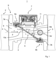
- Reference number 1 in Fig. 1 shows an ultrasonic fluid meter for determining the fluid pressure p and the flow velocity v of a fluid 8 in a fluid supply network 2 for fluid 8, e.g. B. Water.
- the ultrasonic fluid meter 1 is intended to be integrated into the fluid supply network 2, e.g. B. a piping system to be installed. It is a connection housing 3 with an inlet 4 and an outlet 5 provided, wherein the connection housing 3 each has a flange 9 on the inlet and outlet sides for connection to further elements of the fluid supply network 2.
- screw connections or threads or other pipe connections can also be provided for connection to elements of the fluid supply network 2.
- the ultrasonic measuring section 6 is formed by a first ultrasonic transducer 6a and an obliquely opposite second ultrasonic transducer 6b.
- the ultrasonic transducers 6a, 6b are mounted in pockets 3a, 3b of the connection housing 3. Both ultrasonic transducers 6a, 6b can each send an ultrasonic signal 10a, 10b and each can receive an ultrasonic signal 10b, 10a sent by the other ultrasonic transducer 6b, 6a.
- the transmitted and received ultrasound signals 10a, 10b are recorded and evaluated using a control and computing unit 7.
- control and computing unit 7 can also forward transmitted and/or received ultrasound signals 10a, 10b to a headend (not shown) wirelessly or by wire, the headend being designed to evaluate the transmitted and received ultrasound signals 10a, 10b.
- a temperature sensor 11 for detecting the temperature T of the fluid 8 is provided on the connection housing 3.
- a second, in Fig. 1 Ultrasonic measuring section may be present, which is provided by an additional ultrasonic transducer 6a 'and one in Fig. 1 Ultrasonic transducer 6b ⁇ , also not shown (see. Fig. 6 ) is formed.
- Fig. 2 shows the ultrasonic transducer 6a of the ultrasonic counter 1 in an enlarged view.
- the ultrasonic transducer 6a has a disk-shaped transducer body 12a in the form of a piezo element with contact electrodes, not shown, for generating an ultrasonic signal 10a or for detecting an ultrasonic signal 10b.
- the converter body 12a is located in a converter housing 23a and is pressed via a spring 31a onto the inside of a wall 22a of the converter housing 23a, so that it preferably has no gap on the wall 22a is applied.
- the wall 22a with a thickness D 22a is penetrated by the ultrasound signals 10a, 10b.
- the converter housing 23a is preferably made of plastic.
- the ultrasonic transducer 6b has the same structure and also has a transducer body 12b, a spring 31b and a transducer housing 23b with a wall 22b with a thickness D 22b .
- Fig. 3 shows an example of a control and computing unit 7 of the ultrasonic counter 1, which has outputs 13 for generating transmission signals 14a, 14b for generating the respective ultrasonic signal 10a, 10b and inputs 15 for detecting received signals 16a, 16b of the respectively received ultrasonic signal 10a, 10b as well as for Detecting a temperature signal 17 of the temperature sensor 11.
- a transmission signal 14c can be sent to the headend, not shown, and a reception signal 16c can be received by the headend.
- a processor 18, e.g. B. a microcontroller with an oscillator 19, e.g. B. a quartz oscillator is provided to generate a time reference.
- the control and computing unit 7 can also have a memory 20, an accumulator 21, an FPGA 29 or other electrical elements or circuits 30, for example communication modules, for wireless or wired sending and receiving of data, e.g. B. wirelessly via radio protocols or wired via MBus or LBus, time reception modules, e.g. B. for DCF77 signals or position modules, e.g. B. GPS.
- the communication module can also be set up to send data to the headend via the output 13 or to receive data from it via the input 15.
- the measured ultrasonic transit times t 1 , t 2 correspond approximately to the fluid transit times t 1,Fluid , t 2,Fluid , ie the ultrasonic transit times through the fluid 8.
- deviations can occur when measuring the ultrasound transit times t 1 , t 2 .
- Such deviations in the measured ultrasonic travel times t 1 and/or t 2 can be caused by various influences, such as the length L of the ultrasonic measuring section 6 or a change in length ⁇ L thereof, an ultrasonic travel time component along the ultrasonic measuring section 6 that is not in the fluid 8, or a change in the same, an ultrasonic transit time component within the ultrasonic measuring section, which lies in the fluid 8, or a change therein, an attachment and/or position of the ultrasonic transducer to the ultrasonic measuring section 6 or a change therein, a latency of the signal processing or a change therein and/or a flow rate or a change thereof , caused. While these transit time deviations can be partially compensated for when determining the flow velocity v due to the formation of the difference, the influences when determining the ultrasonic velocity of the fluid c fluid or the pressure determination derived from it lead to larger measurement deviations without further measures.
- methods 28 according to the invention are therefore used to determine the fluid pressure p.
- Fig. 4 shows a schematic representation of a method 28 according to the invention. From a measured ultrasonic transit time 24, t 1 or t 2 or from the measured ultrasonic transit times 24, t 1 and t 2 , and a measured temperature 27, the temperature T of the fluid 8, is calculated using a mathematical Compensation 25 determines the fluid pressure 26.
- Fig. 5 shows an embodiment of the method 28 according to the invention.
- the method 28 can include a mathematical compensation 25 of one or more influences 25a-25f.
- the compensation can be based on purely mathematical calculations, ie analytical or numerical calculations.
- the input variables (X 1 , X 2 , ...X N ) of the calculations can be based on measured values, but in particular no reference measurement of the output variables Y is required.
- the control and computing unit 7 is set up to carry out the calculations of the method 28 and/or forward the data to a headend, the headend being set up to carry out the method 28 for determining the fluid pressure p.
- data can also be transmitted from the headend to the control and computing unit 7.
- Data can be, for example, the measured ultrasound transit times t 1 and/or t 2 .
- the mathematical compensation 25 can also be carried out on the control and computing unit 7 and/or on the headend, whereby the data can be the results or partial results of the mathematical compensation 25.
- the housing temperature T housing can be the measured temperature T of the fluid 8, assuming that the housing has the same temperature as the fluid 8. Alternatively, however, additional temperature sensors can also be present in or on the connection housing 3, which are used to determine the housing temperature T housing .
- the housing can also have steel, for example stainless steel, or plastic or another material or a combination of materials suitable for fluid lines.
- one or more non-linear expansion coefficients can also be taken into account in the calculation.
- a numerical calculation using finite element methods is also conceivable, for example in the case of inhomogeneous heat distribution.
- FEM finite element methods
- a temperature gradient within the housing can also be taken into account, which is simulated, for example, on the basis of measured temperatures from several temperature sensors.
- the ultrasonic transit time component t correction can, as in Fig. 2 shown is the ultrasound transit time t wall,22a through the wall 22a of the transducer housing 23a of the Be ultrasonic transducer 6a.
- the ultrasound transit time components of the walls of both ultrasonic transducers 6a, 6b can also be different, for example due to different thicknesses D 22a , D 22b and/or different ultrasound velocities c wall,22a , c wall,22b .
- t 2 , Fluid , corrected t 2 ⁇ t wall , 22 a ⁇ t wall , 22 b
- non-linear expansion coefficients ( ⁇ wall, 22a , ⁇ wall, 22a, ...) can also be taken into account in the calculation or FEM can be used.
- the wall temperature T wall,22a can correspond to the temperature T of the fluid 8.
- a change in thickness ⁇ D 22b of the wall 22b can be determined with an expansion coefficient ⁇ wall, 22b and a wall temperature T wall, 22b , or both changes in thickness ⁇ D 22a , ⁇ D 22b can be the same.
- the thicknesses D 22a , D 22b and/the change in thickness ⁇ D 22a , ⁇ D 22b can also lead to a change in length ⁇ L of the ultrasonic measuring section and can be used to correct it.
- a thermal-related change in the ultrasonic velocities ⁇ c wall,22a , ⁇ c wall,22b of the walls 22a, 22b can be taken into account.
- material differences between e.g. B. different lot numbers during production lead to a change in the ultrasonic speeds.
- an ultrasound transit time component within the ultrasound measuring section that lies in the fluid, or a change therein 25c can also be compensated for.
- a change in the ultrasonic speed ⁇ c fluid is not a change due to a change in the fluid pressure p, but can arise, for example, due to a change in the composition of the fluid (e.g. a change in the hardness of water, ie the lime content of the water).
- the fluid itself can change, e.g. B. Oil instead of water.
- an ultrasonic transducer 6a, 6b is tilted by the angle V to the ultrasonic measuring section 6 (see Fig. Fig. 2 ).
- the angle V can be the same or different for both ultrasonic transducers 6a, 6b, and this influence can be calculated the same or differently for both ultrasonic transducers using the formulas described above.
- the thickness D can be the thickness of a wall D 22a , D 22b .
- An angle change ⁇ V to a known tilt V can also occur.
- an ultrasonic transducer 6a, 6b is shifted in the direction of the ultrasonic measuring section 6 by the position x transducer .
- the length L can be the length of the ultrasonic measuring section when the ultrasonic transducer 6a, 6b is not displaced or the nominal length L.
- Both ultrasonic transducers 6a, 6b can also be displaced, with the effect of the displacements partially canceling out if both ultrasonic transducers 6a, 6b are displaced in the same direction, and the effect being increased if the displacements occur in opposite directions.
- the position of one or both ultrasonic transducers can also be shifted transversely to the ultrasonic measuring section with y transducer , which changes the angle W and the length L.
- L can be the nominal length or a measured length of the ultrasonic measuring section without displacement.
- the length can be calculated in the same way as for a displacement y transducer , whereby the angle W can remain the same.
- Position changes ⁇ x transducer , ⁇ y transducer , ⁇ z transducer with respect to known position deviations x transducer , y transducer , z transducer can also be taken into account.
- the deviations in the position of the ultrasonic transducers 6a, 6b in relation to the ultrasonic measuring section arise, for example, due to the assembly in the pockets 3a, 3b or a manufacturing tolerance of the pockets 3a, 3b.
- a change in position in particular of the surface of the wall 22a, 22b of the ultrasonic transducer housing 23a, 23b facing the fluid, can be corrected.
- the change in position can be caused, for example, by thermal expansion of the wall 22a, 22b and/or the ultrasonic transducer housing 23a, 23b and can be corrected as already described.
- the ultrasound transit time t 1 and/or t 2 can also be compensated for by a latency component of the electronics t latency .
- the latency component can, for example, be subtracted from the measured ultrasound transit times t 1 and/or t 2 .
- the latency component results from e.g. B. from the time offset between the respective transmission signal 14a, 14b and the respective transmitted ultrasound signal 10a, 10b and / or the time offset between the respective reception signal 16a, 16b and the respectively received ultrasound signal 10a, 10b.
- Further effects can be the signal processing when determining the ultrasonic transit times t 1 and/or t 2 , transit time differences and/or transit time sums and/or difference of the reciprocals and/or sum of the reciprocals.
- the latency component can be constant, for example, whereas the latency component in signal processing on the processor 18, e.g. B. a microcontroller, can be variable and can be determined individually for each calculation. It is also conceivable to divide the signal processing between the FPGA 29 with a fixed latency component and the processor 18 with a variable latency component, whereby the total latency can be the sum of the two latency components.
- latencies can also arise from the transmission to the headend and can be compensated for.
- the measured ultrasonic transit times t 1 and/or t 2 can be corrected based on the flow with the transit time component t flow , which is caused by the flow.
- the running times t 1,flow,corrected , t 2,flow,corrected for the flow can be used individually to determine the fluid pressure p.
- the corrected transit times t 1, flow rate, corrected , t 2, flow rate, corrected can also be combined with one another and/or with the other mathematical compensations 25 described.
- the flow velocity v can also be determined or derived from the flow or from a quantity proportional to the flow velocity v.
- the fluid pressure p E is first determined based on a map or a look-up table, e.g. B. with the input variables of the measured ultrasonic transit times t 1 and/or t 2 and/or the temperature T and/or the flow velocity v or a variable proportional to the flow velocity v, e.g. B. the flow determined.
- the fluid pressure p E can be determined, for example, in a first step using reference measurements.
- the fluid pressure p E can serve as an input variable for the mathematical compensation 25 to determine the fluid pressure p.
- Fig. 6 shows a cross section of an ultrasonic fluid meter 1, wherein in addition to the ultrasonic measuring section 6, which is formed by the ultrasonic transducers 6a, 6b, an ultrasonic measuring section 6 ', which is formed by the ultrasonic transducers 6a', 6b', can be provided.
- the ultrasonic transit times t 1 , t 2 of the first ultrasonic measuring section 6 can be measured by the control and computing unit 7 or the headend.
- One or more mathematical compensations 25 can be applied to individual, several or all measured ultrasound transit times t 1 , t 2 , t 1 ', t 2 ' be applied.
- the ultrasonic measuring sections 6, 6' are preferably arranged at a right angle to one another with respect to the cross section of the housing 3.
- the ultrasonic measuring sections can also be arranged at different angles or opposite each other (180° to each other).
- Fig. 6 2 two ultrasonic measuring sections 6, 6' are shown, each with two ultrasonic transducers 6a, 6b, 6a', 6b', but a large number of ultrasonic measuring sections 6, 6', ..., 6n can also be provided, each with two ultrasonic transducers 6a, 6b , 6a', 6b', ..., 6a n , 6b n where also a weighted average from the large number of measured ultrasound transit times t 1 , t 2 , t 1 ', t 2 ', ..., t 1 n , t 2 n and/or fluid pressures p, p', ..., p n and/or flow velocities v, v', ..., v n and/or the proportional sizes of the flow velocities v, v', ..., v n and
- the ultrasonic transducers 6b, 6a', 6b', ..., 6a n , 6b n can have the same elements and the same arrangement as the one in Fig. 2 have ultrasonic transducer 6a shown.
- the ultrasonic measuring section can also contain at least one deflection caused by a reflector.
- the ultrasonic measuring section can be designed in a U-shape, with a double deflection by two reflectors.
- the ultrasonic measuring path can, for example, extend from the first ultrasonic transducer transversely to the axis of the connection housing through the fluid and be deflected by a first reflector parallel to the axis of the connection housing.
- a deflection can be carried out by a second reflector, so that the ultrasonic measuring path runs transversely to the axis of the connection housing towards the second ultrasonic transducer.
- the ultrasonic measuring section can also run from the first ultrasonic transducer to a reflector at an angle to the axis of the connection housing and from the reflector and at an angle to the second ultrasonic transducer, for example in the case of a V-shaped deflection.
- several deflections can also take place via a plurality of reflectors, each at an angle to the axis of the connection housing, for example in the case of a W-shaped deflection.
- the present invention can be used both in large water meters and in domestic water meters.
- the mathematical compensations 25 described must be adapted accordingly for the alternative geometries and/or ultrasonic measuring section arrangements.
- the mathematical compensations 25 of the exemplary embodiments can be used individually, but several mathematical compensations 25 of one or more influences 25a-25f can also be applied and/or combined one after the other and/or simultaneously.
Landscapes
- Physics & Mathematics (AREA)
- General Physics & Mathematics (AREA)
- Fluid Mechanics (AREA)
- Electromagnetism (AREA)
- Acoustics & Sound (AREA)
- Measuring Volume Flow (AREA)
Applications Claiming Priority (1)
| Application Number | Priority Date | Filing Date | Title |
|---|---|---|---|
| DE102022115042.9A DE102022115042A1 (de) | 2022-06-15 | 2022-06-15 | Verfahren zur Ermittlung eines Fluiddrucks in einem Fluidversorgungsnetz für Fluid sowie Ultraschallfluidzähler |
Publications (1)
| Publication Number | Publication Date |
|---|---|
| EP4293324A1 true EP4293324A1 (fr) | 2023-12-20 |
Family
ID=86657736
Family Applications (1)
| Application Number | Title | Priority Date | Filing Date |
|---|---|---|---|
| EP23176653.6A Pending EP4293324A1 (fr) | 2022-06-15 | 2023-06-01 | Procédé de détermination d'une pression de fluide dans un réseau d'alimentation en fluide et compteur de fluide à ultrasons |
Country Status (4)
| Country | Link |
|---|---|
| US (1) | US20230408312A1 (fr) |
| EP (1) | EP4293324A1 (fr) |
| CN (1) | CN117232713A (fr) |
| DE (1) | DE102022115042A1 (fr) |
Cited By (1)
| Publication number | Priority date | Publication date | Assignee | Title |
|---|---|---|---|---|
| CN121113210A (zh) * | 2025-11-13 | 2025-12-12 | 青岛乾程科技股份有限公司 | 一种多声道超声波水表的流量补偿方法、超声波水表、设备及介质 |
Citations (5)
| Publication number | Priority date | Publication date | Assignee | Title |
|---|---|---|---|---|
| DE102012022376A1 (de) | 2012-11-15 | 2014-05-15 | Robert Bosch Gmbh | Druck- und Durchflussmessung mittels akustischer Wellen |
| CN104062062A (zh) * | 2014-07-04 | 2014-09-24 | 浙江大学 | 基于反射纵波的压力容器压力检测方法和测量系统 |
| DE102017005207A1 (de) * | 2017-06-01 | 2018-12-06 | Diehl Metering Gmbh | Verfahren zur Bestimmung des Drucks eines Fluids |
| DE102019007608A1 (de) * | 2019-11-02 | 2021-05-06 | Diehl Metering Gmbh | Messeinrichtung und Verfahren zur Ermittlung eines Drucks |
| DE102020002837A1 (de) * | 2020-05-12 | 2021-11-18 | Diehl Metering Gmbh | Verfahren zum Betrieb einer Messeinrichtung und Messeinrichtung |
Family Cites Families (3)
| Publication number | Priority date | Publication date | Assignee | Title |
|---|---|---|---|---|
| JP3216769B2 (ja) | 1995-03-20 | 2001-10-09 | 富士電機株式会社 | クランプオン型超音波流量計における温度圧力補償方法 |
| US8302455B2 (en) * | 2011-02-11 | 2012-11-06 | Daniel Measurement And Control, Inc. | Determining delay times for ultrasonic flow meters |
| CN106932040B (zh) | 2017-03-14 | 2019-06-21 | 浙江正泰仪器仪表有限责任公司 | 一种气体流量的计量方法 |
-
2022
- 2022-06-15 DE DE102022115042.9A patent/DE102022115042A1/de active Pending
-
2023
- 2023-05-19 CN CN202310568215.2A patent/CN117232713A/zh active Pending
- 2023-06-01 EP EP23176653.6A patent/EP4293324A1/fr active Pending
- 2023-06-12 US US18/333,147 patent/US20230408312A1/en active Pending
Patent Citations (5)
| Publication number | Priority date | Publication date | Assignee | Title |
|---|---|---|---|---|
| DE102012022376A1 (de) | 2012-11-15 | 2014-05-15 | Robert Bosch Gmbh | Druck- und Durchflussmessung mittels akustischer Wellen |
| CN104062062A (zh) * | 2014-07-04 | 2014-09-24 | 浙江大学 | 基于反射纵波的压力容器压力检测方法和测量系统 |
| DE102017005207A1 (de) * | 2017-06-01 | 2018-12-06 | Diehl Metering Gmbh | Verfahren zur Bestimmung des Drucks eines Fluids |
| DE102019007608A1 (de) * | 2019-11-02 | 2021-05-06 | Diehl Metering Gmbh | Messeinrichtung und Verfahren zur Ermittlung eines Drucks |
| DE102020002837A1 (de) * | 2020-05-12 | 2021-11-18 | Diehl Metering Gmbh | Verfahren zum Betrieb einer Messeinrichtung und Messeinrichtung |
Cited By (1)
| Publication number | Priority date | Publication date | Assignee | Title |
|---|---|---|---|---|
| CN121113210A (zh) * | 2025-11-13 | 2025-12-12 | 青岛乾程科技股份有限公司 | 一种多声道超声波水表的流量补偿方法、超声波水表、设备及介质 |
Also Published As
| Publication number | Publication date |
|---|---|
| CN117232713A (zh) | 2023-12-15 |
| US20230408312A1 (en) | 2023-12-21 |
| DE102022115042A1 (de) | 2023-12-21 |
Similar Documents
| Publication | Publication Date | Title |
|---|---|---|
| EP3428583B1 (fr) | Procédé de fonctionnement d'un compteur de fluide et compteur de fluide | |
| EP2739944B1 (fr) | Procédé de détection d'un dépôt ou d'une abrasion dans un débitmètre | |
| DE10335665B4 (de) | Massendurchflussmessgerät | |
| DE102014004747B4 (de) | Ultraschall-Durchflussmesser | |
| WO2018114402A1 (fr) | Capteur de mesure de débit massique fonctionnant suivant le principe de coriolis et procédé permettant de déterminer un débit massique | |
| DE102013106108A1 (de) | Verfahren zur Ermittlung eines kompensierten Durchflusses und/oder einer kompensierten Strömungsgeschwindigkeit, Ultraschall-Durchflussmessgerät und Computerprogrammprodukt | |
| EP3209976B1 (fr) | Procédé de mesure de débit par ultrasons directement sur un tuyau et ensemble formant un circuit pour la commande d'une mesure de débit par ultrasons directement sur un tuyau | |
| DE102015105685B3 (de) | Verfahren und Vorrichtung zum Erkennen des Vorhandenseins von Flüssigkeit in einem Gasstrom | |
| DE102011087215A1 (de) | Verfahren zur Wärmemengenmessung mit einem Ultraschall-Durchflussmessgerät | |
| DE102009003020A1 (de) | Laufzeitmessungskorrektur bei einem Strömungssensor | |
| EP3403057B1 (fr) | Compteur de fluide à ultrasons et procédé de détermination de débit et/ou de volume d'un milieu en écoulement | |
| WO2017012811A1 (fr) | Débitmètre à effet vortex | |
| DE10314916A1 (de) | Vorrichtung zur Bestimmung und/oder Überwachung des Volumen- und/oder Massenstroms eines Mediums | |
| DE102017005207A1 (de) | Verfahren zur Bestimmung des Drucks eines Fluids | |
| EP1931948B1 (fr) | Dispositif pour determiner ou controler le debit volumetrique ou massique d'un fluide dans une conduite | |
| EP4293324A1 (fr) | Procédé de détermination d'une pression de fluide dans un réseau d'alimentation en fluide et compteur de fluide à ultrasons | |
| EP4022259B1 (fr) | Débitmètre à induction magnétique et procédé de fonctionnement d'un débitmètre à induction magnétique | |
| DE102016011256A1 (de) | Verfahren zur Durchflussbestimmung eines strömenden Mediums | |
| WO2006000546A1 (fr) | Procede pour etalonner des debitmetres serre-tube a ultrasons | |
| WO2019096576A1 (fr) | Procédé pour la signalisation d'une fréquence standard d'un densimètre, lequel comprend au moins un tube de mesure apte à osciller et destiné au le passage d'un fluide | |
| DE102007061585A1 (de) | Verfahren und Einrichtung zum Kompensieren von die Messgenauigkeit störenden Druckeinflüssen bei Coriolis-Durchflussmessgeräten | |
| DE102012109234A1 (de) | Durchflussmessgerät, sowie Verwendung dieses Durchflussgerätes und Verfahren zur Ermittlung der Fließgeschwindigkeit | |
| WO2010085980A1 (fr) | Débitmètre massique à effet coriolis et procédé pour calculer la proportion de gaz dans un liquide | |
| EP3196604B1 (fr) | Procédé de fonctionnement d'un débitmètre massique à accélération de coriolis et débitmètre massique à accélération de coriolis correspondant | |
| EP4130687B1 (fr) | Système de débitmètre |
Legal Events
| Date | Code | Title | Description |
|---|---|---|---|
| PUAI | Public reference made under article 153(3) epc to a published international application that has entered the european phase |
Free format text: ORIGINAL CODE: 0009012 |
|
| STAA | Information on the status of an ep patent application or granted ep patent |
Free format text: STATUS: THE APPLICATION HAS BEEN PUBLISHED |
|
| AK | Designated contracting states |
Kind code of ref document: A1 Designated state(s): AL AT BE BG CH CY CZ DE DK EE ES FI FR GB GR HR HU IE IS IT LI LT LU LV MC ME MK MT NL NO PL PT RO RS SE SI SK SM TR |
|
| STAA | Information on the status of an ep patent application or granted ep patent |
Free format text: STATUS: REQUEST FOR EXAMINATION WAS MADE |
|
| 17P | Request for examination filed |
Effective date: 20240612 |
|
| RBV | Designated contracting states (corrected) |
Designated state(s): AL AT BE BG CH CY CZ DE DK EE ES FI FR GB GR HR HU IE IS IT LI LT LU LV MC ME MK MT NL NO PL PT RO RS SE SI SK SM TR |
|
| STAA | Information on the status of an ep patent application or granted ep patent |
Free format text: STATUS: EXAMINATION IS IN PROGRESS |
|
| 17Q | First examination report despatched |
Effective date: 20250507 |