EP4293345A1 - Markierungsinspektionsvorrichtung auf einem transparenten essbaren körper und markierungsvorrichtung - Google Patents
Markierungsinspektionsvorrichtung auf einem transparenten essbaren körper und markierungsvorrichtung Download PDFInfo
- Publication number
- EP4293345A1 EP4293345A1 EP22755993.7A EP22755993A EP4293345A1 EP 4293345 A1 EP4293345 A1 EP 4293345A1 EP 22755993 A EP22755993 A EP 22755993A EP 4293345 A1 EP4293345 A1 EP 4293345A1
- Authority
- EP
- European Patent Office
- Prior art keywords
- marking
- unit
- transparent
- conveyance path
- capsule
- Prior art date
- Legal status (The legal status is an assumption and is not a legal conclusion. Google has not performed a legal analysis and makes no representation as to the accuracy of the status listed.)
- Pending
Links
Images

Classifications
-
- G—PHYSICS
- G01—MEASURING; TESTING
- G01N—INVESTIGATING OR ANALYSING MATERIALS BY DETERMINING THEIR CHEMICAL OR PHYSICAL PROPERTIES
- G01N21/00—Investigating or analysing materials by the use of optical means, i.e. using sub-millimetre waves, infrared, visible or ultraviolet light
- G01N21/84—Systems specially adapted for particular applications
- G01N21/88—Investigating the presence of flaws or contamination
- G01N21/95—Investigating the presence of flaws or contamination characterised by the material or shape of the object to be examined
- G01N21/9508—Capsules; Tablets
-
- G—PHYSICS
- G01—MEASURING; TESTING
- G01N—INVESTIGATING OR ANALYSING MATERIALS BY DETERMINING THEIR CHEMICAL OR PHYSICAL PROPERTIES
- G01N21/00—Investigating or analysing materials by the use of optical means, i.e. using sub-millimetre waves, infrared, visible or ultraviolet light
- G01N21/84—Systems specially adapted for particular applications
- G01N21/85—Investigating moving fluids or granular solids
-
- G—PHYSICS
- G01—MEASURING; TESTING
- G01N—INVESTIGATING OR ANALYSING MATERIALS BY DETERMINING THEIR CHEMICAL OR PHYSICAL PROPERTIES
- G01N21/00—Investigating or analysing materials by the use of optical means, i.e. using sub-millimetre waves, infrared, visible or ultraviolet light
- G01N21/84—Systems specially adapted for particular applications
- G01N21/88—Investigating the presence of flaws or contamination
- G01N21/8806—Specially adapted optical and illumination features
-
- G—PHYSICS
- G01—MEASURING; TESTING
- G01N—INVESTIGATING OR ANALYSING MATERIALS BY DETERMINING THEIR CHEMICAL OR PHYSICAL PROPERTIES
- G01N21/00—Investigating or analysing materials by the use of optical means, i.e. using sub-millimetre waves, infrared, visible or ultraviolet light
- G01N21/84—Systems specially adapted for particular applications
- G01N21/88—Investigating the presence of flaws or contamination
- G01N21/8851—Scan or image signal processing specially adapted therefor, e.g. for scan signal adjustment, for detecting different kinds of defects, for compensating for structures, markings, edges
-
- G—PHYSICS
- G01—MEASURING; TESTING
- G01N—INVESTIGATING OR ANALYSING MATERIALS BY DETERMINING THEIR CHEMICAL OR PHYSICAL PROPERTIES
- G01N21/00—Investigating or analysing materials by the use of optical means, i.e. using sub-millimetre waves, infrared, visible or ultraviolet light
- G01N21/84—Systems specially adapted for particular applications
- G01N21/88—Investigating the presence of flaws or contamination
- G01N21/95—Investigating the presence of flaws or contamination characterised by the material or shape of the object to be examined
- G01N21/956—Inspecting patterns on the surface of objects
- G01N21/95607—Inspecting patterns on the surface of objects using a comparative method
-
- G—PHYSICS
- G01—MEASURING; TESTING
- G01N—INVESTIGATING OR ANALYSING MATERIALS BY DETERMINING THEIR CHEMICAL OR PHYSICAL PROPERTIES
- G01N21/00—Investigating or analysing materials by the use of optical means, i.e. using sub-millimetre waves, infrared, visible or ultraviolet light
- G01N21/84—Systems specially adapted for particular applications
- G01N21/88—Investigating the presence of flaws or contamination
- G01N21/95—Investigating the presence of flaws or contamination characterised by the material or shape of the object to be examined
- G01N21/958—Inspecting transparent materials or objects, e.g. windscreens
-
- G—PHYSICS
- G06—COMPUTING OR CALCULATING; COUNTING
- G06T—IMAGE DATA PROCESSING OR GENERATION, IN GENERAL
- G06T7/00—Image analysis
- G06T7/0002—Inspection of images, e.g. flaw detection
- G06T7/0004—Industrial image inspection
- G06T7/0006—Industrial image inspection using a design-rule based approach
-
- G—PHYSICS
- G01—MEASURING; TESTING
- G01N—INVESTIGATING OR ANALYSING MATERIALS BY DETERMINING THEIR CHEMICAL OR PHYSICAL PROPERTIES
- G01N21/00—Investigating or analysing materials by the use of optical means, i.e. using sub-millimetre waves, infrared, visible or ultraviolet light
- G01N21/84—Systems specially adapted for particular applications
- G01N2021/845—Objects on a conveyor
-
- G—PHYSICS
- G01—MEASURING; TESTING
- G01N—INVESTIGATING OR ANALYSING MATERIALS BY DETERMINING THEIR CHEMICAL OR PHYSICAL PROPERTIES
- G01N21/00—Investigating or analysing materials by the use of optical means, i.e. using sub-millimetre waves, infrared, visible or ultraviolet light
- G01N21/84—Systems specially adapted for particular applications
- G01N21/88—Investigating the presence of flaws or contamination
- G01N21/8806—Specially adapted optical and illumination features
- G01N2021/8848—Polarisation of light
-
- G—PHYSICS
- G01—MEASURING; TESTING
- G01N—INVESTIGATING OR ANALYSING MATERIALS BY DETERMINING THEIR CHEMICAL OR PHYSICAL PROPERTIES
- G01N21/00—Investigating or analysing materials by the use of optical means, i.e. using sub-millimetre waves, infrared, visible or ultraviolet light
- G01N21/84—Systems specially adapted for particular applications
- G01N21/88—Investigating the presence of flaws or contamination
- G01N21/8851—Scan or image signal processing specially adapted therefor, e.g. for scan signal adjustment, for detecting different kinds of defects, for compensating for structures, markings, edges
- G01N2021/8854—Grading and classifying of flaws
-
- G—PHYSICS
- G01—MEASURING; TESTING
- G01N—INVESTIGATING OR ANALYSING MATERIALS BY DETERMINING THEIR CHEMICAL OR PHYSICAL PROPERTIES
- G01N21/00—Investigating or analysing materials by the use of optical means, i.e. using sub-millimetre waves, infrared, visible or ultraviolet light
- G01N21/84—Systems specially adapted for particular applications
- G01N21/88—Investigating the presence of flaws or contamination
- G01N21/8851—Scan or image signal processing specially adapted therefor, e.g. for scan signal adjustment, for detecting different kinds of defects, for compensating for structures, markings, edges
- G01N2021/8854—Grading and classifying of flaws
- G01N2021/888—Marking defects
-
- G—PHYSICS
- G01—MEASURING; TESTING
- G01N—INVESTIGATING OR ANALYSING MATERIALS BY DETERMINING THEIR CHEMICAL OR PHYSICAL PROPERTIES
- G01N2201/00—Features of devices classified in G01N21/00
- G01N2201/10—Scanning
- G01N2201/104—Mechano-optical scan, i.e. object and beam moving
- G01N2201/1042—X, Y scan, i.e. object moving in X, beam in Y
-
- G—PHYSICS
- G01—MEASURING; TESTING
- G01N—INVESTIGATING OR ANALYSING MATERIALS BY DETERMINING THEIR CHEMICAL OR PHYSICAL PROPERTIES
- G01N33/00—Investigating or analysing materials by specific methods not covered by groups G01N1/00 - G01N31/00
- G01N33/02—Food
-
- G—PHYSICS
- G01—MEASURING; TESTING
- G01N—INVESTIGATING OR ANALYSING MATERIALS BY DETERMINING THEIR CHEMICAL OR PHYSICAL PROPERTIES
- G01N33/00—Investigating or analysing materials by specific methods not covered by groups G01N1/00 - G01N31/00
- G01N33/15—Medicinal preparations ; Physical properties thereof, e.g. dissolubility
-
- G—PHYSICS
- G06—COMPUTING OR CALCULATING; COUNTING
- G06T—IMAGE DATA PROCESSING OR GENERATION, IN GENERAL
- G06T2207/00—Indexing scheme for image analysis or image enhancement
- G06T2207/30—Subject of image; Context of image processing
- G06T2207/30108—Industrial image inspection
- G06T2207/30128—Food products
Definitions
- the present invention aims to provide a marking inspection device for transparent edible objects capable of accurately inspecting a marking pattern formed on a transparent edible object, and a marking device including the marking inspection device for transparent edible objects.
- the reflective illuminating unit preferably includes: a ring light; a first polarizing plate that is disposed between the ring light and the conveyance path; and a second polarizing plate that is disposed between the camera and the conveyance path, and has a polarizing axis orthogonal to the polarizing axis of the first polarizing plate.
- the reflective illuminating unit preferably further includes a polarizing plate driving unit that moves the second polarizing plate.
- a transparent edible object marking device that includes the marking inspection device for transparent edible objects described above, and the transparent edible object marking device further includes a marking unit that forms a marking pattern on a transparent edible object being conveyed on the conveyance path on the upstream side in the conveying direction of the inspecting imaging unit.
- the marking unit preferably performs marking by emitting laser light.
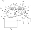
- FIG. 1 is a schematic front view of a transparent edible object marking device (hereinafter simply referred to as the "marking device") according to an embodiment of the present invention.
- the marking device 1 includes a marking inspection device for transparent edible objects (hereinafter simply referred to as the "marking inspection device") 100 that inspects a marking pattern formed on a transparent edible object.
- the marking inspection device 100 includes a conveying unit 2 and an inspecting imaging unit 30.
- a transparent edible object is a soft capsule, a hard capsule, solid food, or the like having transparency, and may be either colorless and transparent, or colored and transparent.
- a transparent edible object formed with a transparent capsule is described as an example.
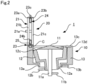
- the rotating shaft 12a of the intermediate ring 12 is disposed so as to be slightly tilted with respect to the rotating shafts 11a and 13a.
- the rotating shafts 11a, 12a, and 13a are connected to driving sources (not shown) such as motors individually provided via decelerators 11b, 12b, and 13b, respectively, and can rotationally drive the disk 11, the intermediate ring 12, and the rotating ring 13, independently of one another.
- the first pulley 21 includes two circular plates 21b and 21c joined by the rotating shaft 21a, with a space being left between the two circular plates.
- the second pulley 22 also includes two circular plates joined by the rotating shaft 22a, with a space being left between the two circular plates.
- the first pulley 21 is a driving pulley connected to a driving motor (not shown), and the second pulley 22 is a driven pulley.
- the first pulley 21 may be a driven pulley
- the second pulley 22 may be a driving pulley.
- the belt member 23 includes two band-like conveying belts 23a and 23b, and the respective conveying belts 23a and 23b are wound around the respective circular plates 21b and 21c of the first pulley 21. Between the two conveying belts 23a and 23b, an opening 23c that is a narrow gap is formed over the entire circumference of the belt member 23.
- the conveying belts 23a and 23b can be formed with flat belts of a soft material such as silicone rubber, for example, but may be formed with V-belts, toothed belts, or the like.
- the guide member 24 includes: a linear portion 24a that is disposed immediately below the vicinity of the belt member 23 extending horizontally along the conveyance path 2a between the first pulley 21 and the second pulley 22; and arcuate portions 24b and 24c provided on both sides of the linear portion 24a in the conveying direction.
- Each of the arcuate portions 24b and 24c is inserted between the two circular plates of each corresponding one of the first pulley 21 and the second pulley 22, and is curved in an arcuate shape along the belt member 23 wound around the first pulley 21 and the second pulley 22.
- the guide member 24 is formed in a hollow cylindrical shape, and a slit-like suctioning portion 25 is formed along the opening 23c in a portion where the guide member 24 faces the opening 23c of the belt member 23.
- the inside of the guide member 24 can be decompressed by an operation of a vacuum pump (not shown), and a capsule C is attracted to the suctioning portion 25 via the opening 23c of the belt member 23, so that the capsule C attracted to the belt member 23 can be conveyed together with the belt member 23.
- the opening 23c of the belt member 23 of this embodiment is continuously formed between the two conveying belts 23a and 23b in the longitudinal direction.
- the belt member 23 may be formed as a single band-like belt, and openings having a circular shape, an elliptical shape, or a slit-like shape may be intermittently formed in the longitudinal direction of the band-like belt.
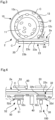
- FIG. 4 is an enlarged plan view of a portion in the vicinity of the conveyance path 2a shown in FIG. 1 .
- the inspecting imaging unit 30 includes a camera 31, a reflective illuminating unit 32, and a transmissive illuminating unit 33.
- the camera 31 is formed with a CCD area camera, a CCD line camera, or the like, is disposed so that the imaging direction becomes orthogonal to the conveyance path 2a in a plan view, and horizontally images a capsule C being conveyed on the conveyance path 2a along the upper surface of the belt member 23.
- the imaging direction of the camera 31 is preferably substantially parallel to the upper surface of the belt member 23.
- imaging may be performed obliquely downward from above the belt member 23.
- the angle between the imaging direction of the camera 31 and the upper surface of the belt member 23 can be set within the range of 0 to 15 degrees.
- the reflective illuminating unit 32 is disposed on the same side of the conveyance path 2a as the camera 31, and illuminates the capsule C with a white LED or the like from the same side as the camera 31.
- the reflective illuminating unit 32 of this embodiment includes a ring light 32a capable of uniformly illuminating the capsule C from the entire circumference, a first polarizing plate 32b, and a second polarizing plate 32c.
- the illuminating light of the ring light 32a may be infrared light or the like, other than visible light.
- the first polarizing plate 32b is formed in a ring-like shape, is disposed in the vicinity of the ring light 32a, and is interposed between the ring light 32a and the conveyance path 2a, so that the capsule C is illuminated with linearly polarized light emitted from the ring light 32a.
- the second polarizing plate 32c is disposed in the vicinity of the camera 31 so as to cover the lens portion of the camera 31, and is interposed between the camera 31 and the conveyance path 2a, so that surface-reflected light from the capsule C passes therethrough and is observed by the camera 31.
- the second polarizing plate 32c is disposed so that the polarizing axis becomes orthogonal to the polarizing axis of the first polarizing plate 32b.
- the second polarizing plate 32c is designed to be movable with a polarizing plate driving unit 32d such as an actuator. As the driving axis of the polarizing plate driving unit 32d rotates, the second polarizing plate 32c can be retracted from the front of the camera 31 as indicated by a dash-dot-dot-dash line in FIG. 4 .
- the polarizing plate driving unit 32d may be designed to linearly move the second polarizing plate 32c and retract the second polarizing plate 32c from the front of the camera 31.
- control unit 70 operations of the conveying unit 2 and the inspecting imaging unit 30 in the marking inspection device 100 are controlled by a control unit 70.
- the marking device 1 of this embodiment includes a marking unit 40, a marking imaging unit 50, and a separating unit 60, in addition to the marking inspection device 100 described above.
- the marking unit 40, the marking imaging unit 50, and the separating unit 60 are provided on the upstream side in the conveying direction of the inspecting imaging unit 30 in the vicinity of the conveyance path 2a. Operations of the marking unit 40, the marking imaging unit 50, and the separating unit 60 are controlled by the control unit 70.
- the marking imaging unit 50 is disposed on the upstream side of the marking unit 40 in the conveying direction, and includes a camera 51, a reflective illuminating unit 52, and a transmissive illuminating unit 53, like the inspecting imaging unit 30.
- the reflective illuminating unit 52 includes a ring light 52a, a first polarizing plate 52b, a second polarizing plate 52c, and a polarizing plate driving unit 52d.
- the configurations and positions of the respective components of the marking imaging unit 50 are similar to the configurations and positions of the respective components of the inspecting imaging unit 30, and therefore, detailed explanation thereof is not made herein.
- the separating unit 60 is disposed between the marking imaging unit 50 and the marking unit 40 in the vicinity of the conveyance path 2a, and can selectively separate the capsule C from the conveyance path 2a by injecting compressed air to the capsule C being conveyed on the conveyance path 2a.
- the separating unit 60 is not limited to any particular configuration, and may be a pusher or the like that physically pushes the capsule C on the conveyance path 2a to separate the capsule C from the conveyance path 2a, for example.
- the capsule C separated from the conveyance path 2a by the operation of the separating unit 60 falls directly or via a chuter (not shown) onto the first conveying device 10 disposed below the conveyance path 2a, and is conveyed again toward the conveyance path 2a.
- the rotational speeds of the disk 11, the intermediate ring 12, and the rotating ring 13 are preferably set so that the rotational speed of the disk 11 becomes the lowest, and the rotational speed of the rotating ring 13 becomes the highest. In this manner, reliable aligned conveyance of the capsules C by the rotating ring 13 can be facilitated.
- the first conveying device 10 is only required to align the capsules C on the conveyance surface 13c of the rotating ring 13 and convey the capsules C in the direction of rotation of the rotating ring 13.
- the respective rotating shafts of the disk 11 and the rotating ring 13 may be tilted with respect to each other, and the capsules C supplied onto the disk 11 may be directly moved onto the conveyance surface 13c of the rotating ring 13.
- the rotating shaft 13a of the rotating ring 13 is preferably disposed in the vertical direction as in this embodiment, but is only required to be disposed to extend in the vertical direction.
- the rotating shaft 13a may be slightly tilted with respect to the vertical direction.
- the direction of conveyance by the rotating ring 13 and the direction of conveyance by the belt member 23 are preferably the same as each other as in this embodiment. With such arrangement, the transfer of the capsules C can be reliably performed. Further, by making the speed of conveyance of the capsules C by the belt member 23 higher than the speed of conveyance of the capsules C by the rotating ring 13, it is possible to widen the alignment pitch of the capsules C being aligned and conveyed by the belt member 23.
- the control unit 70 sets a marking region on the capsule C, and performs marking by controlling the operation of the marking unit 40.
- coordinate data in the reference coordinate system of a marking pattern formed with a character, a number, a symbol, a figure, or the like, or a combination thereof is stored beforehand in a memory.
- the control unit 70 transforms the coordinate data in the reference coordinate system into coordinate data in the machining coordinate system so that a marking pattern is formed along the marking region that has been set in accordance with the posture of the capsule C.
- the control unit 70 then performs drive control on the laser spot of the marking unit 40 in the machining coordinate system.
- the capsule C on which the marking pattern has been formed is conveyed along the conveyance path 2a toward the inspecting imaging unit 30.
- the side surface including the marking region is imaged, and thus, inspecting imaging data is obtained.
- the control unit 70 determines the quality of the marking pattern in the marking region.
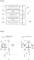
- the control unit 70 turns on the transmissive illuminating unit 33 but turns off the reflective illuminating unit 32, and thus illuminates the capsule C with the transmissive illuminating unit 33, as shown in FIG. 6(a) .
- the term "colorless and transparent” in this specification is not necessarily limited to completely colorless and transparent, and also includes cases where transparency is sufficiently high though the object is slightly colored, and cases where the object is semi-transparent.
- the contour of the capsule C appears because of refraction of light, and the portion corresponding to the marking pattern formed on the surface of the capsule C appears as a shadow in the inspecting imaging data.
- the control unit 70 turns on the reflective illuminating unit 32 but turns off the transmissive illuminating unit 33, and thus illuminates the capsule C with the reflective illuminating unit 32, as shown in FIG. 6(b) .
- the illuminating light emitted from the ring light 32a of the reflective illuminating unit 32 is turned into linearly polarized light by the first polarizing plate 32b, and illuminates the capsule C.
- the surface-reflected light from the capsule C then enters the camera 31 through the second polarizing plate 32c.
- the polarizing axis of the second polarizing plate 32c is orthogonal to the polarizing axis of the first polarizing plate 32b, reflection of illuminating light due to regular reflection light from the surface of the capsule C is removed, and only diffusely reflected light is observed by the camera 31. Accordingly, it is possible to effectively reduce the glare on the surface of the colored transparent capsule C, and obtain the inspecting imaging data in which the contour of the capsule C and the marking are clear.
- Whether the capsule C is colorless and transparent, or is colored and transparent can be determined by the operator, and be input to the control unit 70. In this case, it is possible to determine whether the capsule C is colorless and transparent, or is colored and transparent by comparing pieces of inspecting imaging data obtained under the respective conditions of reflective illumination by the reflective illuminating unit 32 and transmissive illumination by the transmissive illuminating unit 33.
- the control unit 70 may be designed to measure the illuminating light transmittance of the capsule C, and automatically determine that the capsule C is colorless and transparent in a case where the illuminating light transmittance is equal to or higher than a threshold, but automatically determine that the capsule C is colored and transparent in a case where the illuminating light transmittance is lower than the threshold.
- the posture of a transparent edible object such as the capsule C may be specified on the basis of the position, the orientation, and the like of a portion having a characteristic shape appearing on the surface of the transparent edible object, such as a split line or an engraved mark, other than the contour of the transparent edible object.
- control unit 70 reference pattern data corresponding to the marking pattern is stored beforehand in a memory unit.
- the control unit 70 determines the quality of the marking pattern by extracting the marking pattern data from the marking region in the inspecting imaging data and comparing the marking pattern data with the reference pattern data.
- the method for comparing the marking pattern data with the reference pattern data is not limited to any particular method, and areas, shapes, or the like can be compared, for example.
- the marking pattern data and the reference pattern data are compared with each other in terms of area, for example, a check is made to determine whether the absolute value of the difference between the areas of the two pieces of data is within a threshold. In a case where the absolute value is within the threshold, the marking pattern can be determined to be good. In a case where the absolute value is beyond the threshold, the marking pattern can be determined to be defective. More specifically, pixels having a predetermined luminance or higher from the inside of the image are regarded as a marking with the use of a binarization algorithm, and area comparison can be performed in accordance with the number of extracted pixels.
- the marking pattern data and the reference pattern data are compared with each other in terms of shape, for example, a check is made to determine whether the concordance rate is higher than a threshold when the two shapes are overlapped on each other. In a case where the concordance rate is higher than the threshold, the marking pattern can be determined to be good. In a case where the concordance rate is lower than the threshold, the marking pattern can be determined to be defective. More specifically, the contour shape of the marking pattern is registered beforehand through geometric pattern matching, and the quality of the marking pattern can be determined from a concordance rate that is the similarity between a search result image obtained by a model search in the image and a model image. Further, the comparison in terms of area and the comparison in terms of shape can be combined in determining the quality of the marking pattern.
- the inspecting imaging unit 30 can obtain inspecting imaging data in which the posture and the marking pattern of the transparent edible object are clear, and thus, the marking pattern can be inspected with high precision.
- the illumination condition for the marking imaging unit 50 is preferably the same as the illumination condition for the inspecting imaging unit 30.
- reflective illumination is performed by the reflective illuminating unit 52 in the marking imaging unit 50.
- transmissive illumination is performed by the transmissive illuminating unit 33 in the inspecting imaging unit 30
- reflective illumination is performed by the transmissive illuminating unit 53 in the marking imaging unit 50.
- the control unit 70 determines whether a seam is present in the marking region set in the marking imaging data, and, if a seam is present, calculates the size of the seam.
- the position of a seam on the surface of a capsule C being conveyed on the conveyance path 2a is random. Therefore, in a case where a seam S does not overlap the marking region M as shown in FIG. 8(a) , any marking defect problem does not occur.
- the seam S overlaps the marking region M as shown in FIG. 8(b) , visibility of marking might become lower.
- control unit 70 causes the capsule C to pass without operating the separating unit 60, and performs marking at the timing when the capsule C is conveyed to the marking unit 40.
- the capsule C on which the marking pattern has been formed is then subjected to the marking pattern inspection by the marking inspection device 100 as described above.
Landscapes
- General Physics & Mathematics (AREA)
- Physics & Mathematics (AREA)
- Immunology (AREA)
- Pathology (AREA)
- Analytical Chemistry (AREA)
- Biochemistry (AREA)
- General Health & Medical Sciences (AREA)
- Life Sciences & Earth Sciences (AREA)
- Health & Medical Sciences (AREA)
- Chemical & Material Sciences (AREA)
- Engineering & Computer Science (AREA)
- Computer Vision & Pattern Recognition (AREA)
- Quality & Reliability (AREA)
- Theoretical Computer Science (AREA)
- Signal Processing (AREA)
- Investigating Materials By The Use Of Optical Means Adapted For Particular Applications (AREA)
Applications Claiming Priority (2)
| Application Number | Priority Date | Filing Date | Title |
|---|---|---|---|
| JP2021022543 | 2021-02-16 | ||
| PCT/JP2022/004665 WO2022176672A1 (ja) | 2021-02-16 | 2022-02-07 | 透明可食体のマーキング検査装置およびマーキング装置 |
Publications (2)
| Publication Number | Publication Date |
|---|---|
| EP4293345A1 true EP4293345A1 (de) | 2023-12-20 |
| EP4293345A4 EP4293345A4 (de) | 2025-03-05 |
Family
ID=82930491
Family Applications (1)
| Application Number | Title | Priority Date | Filing Date |
|---|---|---|---|
| EP22755993.7A Pending EP4293345A4 (de) | 2021-02-16 | 2022-02-07 | Markierungsinspektionsvorrichtung auf einem transparenten essbaren körper und markierungsvorrichtung |
Country Status (5)
| Country | Link |
|---|---|
| US (1) | US12385848B2 (de) |
| EP (1) | EP4293345A4 (de) |
| JP (1) | JPWO2022176672A1 (de) |
| KR (1) | KR20230142445A (de) |
| WO (1) | WO2022176672A1 (de) |
Families Citing this family (2)
| Publication number | Priority date | Publication date | Assignee | Title |
|---|---|---|---|---|
| US12534307B2 (en) | 2023-04-20 | 2026-01-27 | Grupo Bimbo, S.A.B. De C.V. | Food delivery system for packaging of food and method of delivering food to be packaged |
| US12258158B2 (en) * | 2023-04-20 | 2025-03-25 | Grupo Bimbo S.A.B. De C.V. | Food delivery system for packaging of food and method of delivering food to be packaged |
Family Cites Families (16)
| Publication number | Priority date | Publication date | Assignee | Title |
|---|---|---|---|---|
| JPS58137740A (ja) * | 1982-02-10 | 1983-08-16 | Fuji Electric Co Ltd | 欠陥判定処理回路 |
| JPH07151694A (ja) | 1993-11-30 | 1995-06-16 | Electroplating Eng Of Japan Co | 外観検査装置 |
| JPH08271433A (ja) | 1995-03-30 | 1996-10-18 | Nikon Corp | 錠剤検査装置 |
| JPH10282014A (ja) | 1997-04-10 | 1998-10-23 | Mitsui Chem Inc | 偏光板付き表面欠陥検出装置 |
| JP2002071573A (ja) | 2000-09-01 | 2002-03-08 | Daihatsu Motor Co Ltd | 塗布状態検査方法およびその装置 |
| TW200702656A (en) * | 2005-05-25 | 2007-01-16 | Olympus Corp | Surface defect inspection apparatus |
| JP2010151457A (ja) * | 2008-12-24 | 2010-07-08 | Kirin Techno-System Co Ltd | 容器のラベル検査装置 |
| WO2012127827A1 (ja) * | 2011-03-24 | 2012-09-27 | パナソニック株式会社 | 錠剤検査装置およびこれを用いた錠剤検査方法 |
| KR20180122044A (ko) * | 2011-04-28 | 2018-11-09 | 가부시키가이샤 유야마 세이사쿠쇼 | 약제 감사 장치 및 약제 분포 장치 |
| JP2012234081A (ja) | 2011-05-06 | 2012-11-29 | Oputeikon:Kk | 照明装置および光学装置 |
| DE102011078833A1 (de) * | 2011-07-07 | 2013-01-10 | 3D-Micromac Ag | Verfahren und Vorrichtung zum Detektieren einer Markierung an einem Objekt |
| KR102167067B1 (ko) * | 2013-07-16 | 2020-10-16 | 쿠오리카프스 가부시키가이샤 | 가식체의 마킹장치 및 방법 |
| JP6100136B2 (ja) * | 2013-09-30 | 2017-03-22 | 富士フイルム株式会社 | 薬剤認識装置及び方法 |
| WO2016103286A1 (en) * | 2014-12-24 | 2016-06-30 | Datalogic Ip Tech S.R.L. | System and method for identifying the presence or absence of transparent pills in blister packer machines using high resolution 3d stereo reconstruction based on color linear cameras |
| KR102936089B1 (ko) * | 2017-04-14 | 2026-03-09 | 가부시키가이샤 유야마 세이사쿠쇼 | 약제 분류 장치, 분류 용기 및 약제 반환 방법 |
| JP2018186962A (ja) | 2017-04-28 | 2018-11-29 | 株式会社Screenホールディングス | 画像取得装置、検査装置、錠剤印刷装置、および画像取得方法 |
-
2022
- 2022-02-07 EP EP22755993.7A patent/EP4293345A4/de active Pending
- 2022-02-07 KR KR1020237017460A patent/KR20230142445A/ko active Pending
- 2022-02-07 JP JP2023500737A patent/JPWO2022176672A1/ja active Pending
- 2022-02-07 WO PCT/JP2022/004665 patent/WO2022176672A1/ja not_active Ceased
- 2022-02-07 US US18/264,972 patent/US12385848B2/en active Active
Also Published As
| Publication number | Publication date |
|---|---|
| EP4293345A4 (de) | 2025-03-05 |
| JPWO2022176672A1 (de) | 2022-08-25 |
| KR20230142445A (ko) | 2023-10-11 |
| WO2022176672A1 (ja) | 2022-08-25 |
| US12385848B2 (en) | 2025-08-12 |
| US20240053277A1 (en) | 2024-02-15 |
Similar Documents
| Publication | Publication Date | Title |
|---|---|---|
| CA2914111C (en) | Apparatus and method for marking edible object | |
| US6384421B1 (en) | Vision system for industrial parts | |
| JP5567079B2 (ja) | プリフォーム検査装置及び検査方法 | |
| EP4293345A1 (de) | Markierungsinspektionsvorrichtung auf einem transparenten essbaren körper und markierungsvorrichtung | |
| CN109844505B (zh) | 玻璃容器的烧伤检查装置 | |
| JP6199042B2 (ja) | 容器の検査装置 | |
| US20200358935A1 (en) | Image acquisition device, image acquisition method and inspection apparatus | |
| US7697132B2 (en) | Machine for inspecting glass containers | |
| EP3283871B1 (de) | Vorrichtung und verfahren zur optischen inspektion von objekten, insbesondere metalldeckeln | |
| CN107430077B (zh) | 型坯的光学检测设备和方法 | |
| EP4275829B1 (de) | Kapselmarkierungsvorrichtung und -verfahren | |
| JP4986255B1 (ja) | 容器口部検査方法及び装置 | |
| JP3989739B2 (ja) | 検査装置 | |
| JP6897929B2 (ja) | 透明物品の検査装置 | |
| EP4286836A1 (de) | System und verfahren zur inspektion von markierungen auf der oberfläche von behältern | |
| JP2006258551A (ja) | 液内異物検査装置 | |
| JP4177204B2 (ja) | 容器充填液体の異物検査装置 | |
| JP2013104659A (ja) | 液面浮遊異物検査方法及び装置 | |
| JP2002267612A (ja) | 透明容器等の充填液体中の異物検査装置及びシステム | |
| JP6073261B2 (ja) | びん底検査装置 | |
| JP5257224B2 (ja) | 物品検査方法 | |
| JP2022072877A (ja) | びん底検査装置 | |
| CN119985320A (zh) | 平行型双相机六视角成像系统 | |
| JPH06102186A (ja) | 部品供給装置 |
Legal Events
| Date | Code | Title | Description |
|---|---|---|---|
| STAA | Information on the status of an ep patent application or granted ep patent |
Free format text: STATUS: THE INTERNATIONAL PUBLICATION HAS BEEN MADE |
|
| PUAI | Public reference made under article 153(3) epc to a published international application that has entered the european phase |
Free format text: ORIGINAL CODE: 0009012 |
|
| STAA | Information on the status of an ep patent application or granted ep patent |
Free format text: STATUS: REQUEST FOR EXAMINATION WAS MADE |
|
| 17P | Request for examination filed |
Effective date: 20230913 |
|
| AK | Designated contracting states |
Kind code of ref document: A1 Designated state(s): AL AT BE BG CH CY CZ DE DK EE ES FI FR GB GR HR HU IE IS IT LI LT LU LV MC MK MT NL NO PL PT RO RS SE SI SK SM TR |
|
| DAV | Request for validation of the european patent (deleted) | ||
| DAX | Request for extension of the european patent (deleted) | ||
| A4 | Supplementary search report drawn up and despatched |
Effective date: 20250204 |
|
| RIC1 | Information provided on ipc code assigned before grant |
Ipc: G01N 21/85 20060101AFI20250129BHEP |