EP4293626A1 - Procédé et dispositif de fourniture d'un modèle tridimensionnel d'un objet - Google Patents
Procédé et dispositif de fourniture d'un modèle tridimensionnel d'un objet Download PDFInfo
- Publication number
- EP4293626A1 EP4293626A1 EP22179088.4A EP22179088A EP4293626A1 EP 4293626 A1 EP4293626 A1 EP 4293626A1 EP 22179088 A EP22179088 A EP 22179088A EP 4293626 A1 EP4293626 A1 EP 4293626A1
- Authority
- EP
- European Patent Office
- Prior art keywords
- model
- volume data
- image synthesis
- providing
- visualization
- Prior art date
- Legal status (The legal status is an assumption and is not a legal conclusion. Google has not performed a legal analysis and makes no representation as to the accuracy of the status listed.)
- Pending
Links
Images

Classifications
-
- G—PHYSICS
- G06—COMPUTING OR CALCULATING; COUNTING
- G06T—IMAGE DATA PROCESSING OR GENERATION, IN GENERAL
- G06T17/00—Three-dimensional [3D] modelling for computer graphics
-
- G—PHYSICS
- G06—COMPUTING OR CALCULATING; COUNTING
- G06T—IMAGE DATA PROCESSING OR GENERATION, IN GENERAL
- G06T15/00—Three-dimensional [3D] image rendering
- G06T15/08—Volume rendering
-
- G—PHYSICS
- G06—COMPUTING OR CALCULATING; COUNTING
- G06T—IMAGE DATA PROCESSING OR GENERATION, IN GENERAL
- G06T7/00—Image analysis
- G06T7/10—Segmentation; Edge detection
- G06T7/12—Edge-based segmentation
-
- G—PHYSICS
- G16—INFORMATION AND COMMUNICATION TECHNOLOGY [ICT] SPECIALLY ADAPTED FOR SPECIFIC APPLICATION FIELDS
- G16H—HEALTHCARE INFORMATICS, i.e. INFORMATION AND COMMUNICATION TECHNOLOGY [ICT] SPECIALLY ADAPTED FOR THE HANDLING OR PROCESSING OF MEDICAL OR HEALTHCARE DATA
- G16H30/00—ICT specially adapted for the handling or processing of medical images
- G16H30/40—ICT specially adapted for the handling or processing of medical images for processing medical images, e.g. editing
-
- G—PHYSICS
- G16—INFORMATION AND COMMUNICATION TECHNOLOGY [ICT] SPECIALLY ADAPTED FOR SPECIFIC APPLICATION FIELDS
- G16H—HEALTHCARE INFORMATICS, i.e. INFORMATION AND COMMUNICATION TECHNOLOGY [ICT] SPECIALLY ADAPTED FOR THE HANDLING OR PROCESSING OF MEDICAL OR HEALTHCARE DATA
- G16H50/00—ICT specially adapted for medical diagnosis, medical simulation or medical data mining; ICT specially adapted for detecting, monitoring or modelling epidemics or pandemics
- G16H50/50—ICT specially adapted for medical diagnosis, medical simulation or medical data mining; ICT specially adapted for detecting, monitoring or modelling epidemics or pandemics for simulation or modelling of medical disorders
-
- H—ELECTRICITY
- H04—ELECTRIC COMMUNICATION TECHNIQUE
- H04N—PICTORIAL COMMUNICATION, e.g. TELEVISION
- H04N13/00—Stereoscopic video systems; Multi-view video systems; Details thereof
- H04N13/20—Image signal generators
- H04N13/275—Image signal generators from three-dimensional [3D] object models, e.g. computer-generated stereoscopic image signals
-
- G—PHYSICS
- G06—COMPUTING OR CALCULATING; COUNTING
- G06T—IMAGE DATA PROCESSING OR GENERATION, IN GENERAL
- G06T2200/00—Indexing scheme for image data processing or generation, in general
- G06T2200/24—Indexing scheme for image data processing or generation, in general involving graphical user interfaces [GUIs]
-
- G—PHYSICS
- G06—COMPUTING OR CALCULATING; COUNTING
- G06T—IMAGE DATA PROCESSING OR GENERATION, IN GENERAL
- G06T2210/00—Indexing scheme for image generation or computer graphics
- G06T2210/41—Medical
Definitions
- the invention relates to methods and devices for generating and providing a virtual three-dimensional model (3D model) of a real three-dimensional object.
- the 3D model is made available for distribution to and use by a user, who can use the 3D model to display different views of the object.
- the modeling, reconstruction or visualization of three-dimensional objects has a wide range of applications in the fields of medicine (e.g. CT, PET), physics (e.g. electronic structure of large molecules) or geophysics (nature and location of earth layers).
- the object to be examined is irradiated (e.g. using electromagnetic waves or sound waves) in order to examine its properties.
- the scattered radiation is detected and properties of the object are determined from the detected values.
- the result is usually a physical quantity (e.g. density, tissue type, elasticity, speed), the value of which is determined for the object.
- a virtual grid is usually used, at whose grid points the value of the size is determined. These grid points are commonly referred to as voxels.
- voxel is a synthesis word formed from the terms “volume” and “pixel”.
- a voxel corresponds to the spatial coordinate of a grid point to which the value of a quantity at this location is assigned. This is usually a physical quantity that can be represented as a scalar or vector field, i.e. the corresponding field value is assigned to the spatial coordinate.
- the object data obtained in this way is also referred to as volume data.
- a three-dimensional representation of the object or body is usually generated from the voxels on a two-dimensional display surface (e.g. a screen or a pane or lens of a so-called “augmented reality glasses”).
- voxels defined in three dimensions
- pixels defined in two dimensions
- the pixels of the visualization image are also referred to below as visualization pixels.
- the mapping is commonly referred to as volume rendering. How the volume reproduction is carried out depends on how information contained in the voxels is reproduced using the pixels.
- RGBA values are determined from the voxels for sampling points along the rays and combined into pixels for a two-dimensional image using alpha compositing or alpha blending.
- R, G and B stand for the color components red, green and blue, which make up the color contribution of the corresponding sampling point.
- A stands for the ALPHA value, which is a measure of the transparency at the sampling point. The respective transparency is used when overlaying RGB values at sample points to the pixel. Lighting effects are usually taken into account using a lighting model as part of a process called “shading”.
- a primary technical obstacle to implementing an interactive volume rendering system is processing large amounts of data quickly, efficiently, and locally.
- Fast volume rendering is a challenge, especially on devices with limited computing or graphics performance. Examples of such devices are mobile devices such as smartphones or tablets. These are usually equipped with energy-saving processors (“System on a Chip”), which have comparatively little computing power compared to modern PCs.
- System on a Chip energy-saving processors
- the portability of a volume rendering system is often limited because both the volume rendering algorithm and the volume data must be ported for local use. This is often not possible due to the volume of data and for data security reasons.
- finding suitable parameters to generate a suitable visualization image is often non-trivial and difficult for the end user to understand, since the end user is typically not an expert in volume rendering methods.
- a computer-implemented method for providing a 3D model of a three-dimensional object represented by volume data has several steps.
- One step is aimed at providing the volume data.
- a further step is aimed at providing an image synthesis algorithm, which image synthesis algorithm for visualizing the three-dimensional object by mapping the volume data onto visualization pixels of a two-dimensional one Visualization image is formed.
- a further step is aimed at determining a parameter set for controlling the image synthesis algorithm, which parameter set is suitable for using the image synthesis algorithm to generate a set of several different visualization images based on the volume data set.
- a further step is directed towards generating the set of several different visualization images by mapping the volume data with the image synthesis algorithm using the parameter set.
- a further step is aimed at computing the 3D model based on the set of multiple visualization images.
- a further step is aimed at providing the 3D model (for a user).
- the volume data may include a plurality of voxels.
- a voxel (“volume pixel" or three-dimensional pixel) is a volume element that represents a value on a regular grid in three-dimensional (3D) space.
- Voxels are analogous to pixels, which represent two-dimensional (2D) image data. As with pixels, the voxels themselves typically do not contain their position in space (their coordinates), but rather their coordinates are derived based on their positions relative to other voxels (i.e., their positions in the data structure that forms a single volume image).
- the value of a voxel can represent various physical properties of the three-dimensional object, such as a local density.
- the values are expressed in Hounsfield units, which represent the opacity of an imaged material in relation to X-rays.
- the volume data thus describes a three-dimensional object in an object volume.
- the volume data can indicate a (particularly inhomogeneous) density of the three-dimensional object in the object volume.
- the volume data can in particular be provided by a medical imaging method.
- the imaging methods can include, for example, X-ray fluoroscopy, computer tomography (CT), magnetic resonance imaging (MR), ultrasound and/or positron emission tomography (PET).
- CT computer tomography
- MR magnetic resonance imaging
- PET positron emission tomography
- the three-dimensional object can be a body or body part of a patient.
- the three-dimensional object can include one or more of the patient's organs.
- the image synthesis algorithm can be understood in particular as a computer program product that is designed to image the volume data on a two-dimensional projection surface or to reproduce the volume of the three-dimensional object or to render the volume of the three-dimensional object.
- the projection surface is given by the visualization image.
- the image synthesis algorithm can have program components in the form of one or more instructions for a processor for calculating the visualization image.
- Other terms for image synthesis algorithms include "renderer", “rendering algorithm” or "volume renderer”.
- the image synthesis algorithm can be provided, for example, by being stored in a storage device or loaded into a working memory of a suitable data processing device or generally made available for use.
- the image synthesis algorithm can implement various methods for visualizing a volume data set individually or in combination.
- the image synthesis algorithm can have a ray casting module and/or a path tracing module.
- the image synthesis algorithm maps the volume data onto the visualization pixels.
- the image synthesis algorithm for a visualization image can have a specific view, perspective, scene illumination, transfer function, transparency of one or more areas of the volume data, a cutting plane through the volume data, an area of interest within the volume data, and / or one or more Realize additional information to be displayed in the visualization image.
- a visualization image is the two-dimensional result of the volume rendering process.
- the visualization image is composed of several visualization pixels. Just like the volume data, the visualization images can be saved.
- the parameter set represents those input parameters for the image synthesis algorithm, on the basis of which the image synthesis algorithm can generate one or more visualization images of the volume data.
- the parameter set can be viewed as a control command set for the image synthesis algorithm.
- the parameter set can encode which views, perspectives, scene illumination, transfer functions, transparencies, sectional planes, etc. are implemented in the individual visualization images.
- the parameter set can specify the generation of N different visualization images.
- N can be greater than or equal to 6, preferably greater than 10, more preferably greater than 20 and more preferably greater than 50.
- 3D modeling is the process of developing a mathematical and coordinate-based representation of any surface of an object in three dimensions.
- Three-dimensional (3D) models represent a physical object, for example, by using a collection of points in 3D space connected by various geometric entities such as triangles, lines, curved surfaces, etc. Your surfaces can be further enhanced using texture mapping To be defined.
- the 3D model can have a lower memory requirement than the volume data.
- the 3D model therefore represents a digital or virtual model of the object.
- the 3D model represents a digital or virtual view model of the object.
- two-dimensional images can be generated by 3D rendering. Rendering a 3D model is often easier than rendering volume data. By manipulating the 3D model by a user, the 3D model can therefore be viewed continuously from different views.
- a three-dimensional reconstruction of the 3D model is carried out from the individual visualization images, which in particular show different views of the object.
- the visualization images only represent discrete views that can be used to interpolate when calculating the 3D model.
- the calculation of 3D models from individual images is generally known.
- the 3D model can be provided as a data set, for example.
- the 3D model can be stored in a storage device and thus made available.
- the 3D model can be made available for download.
- the 3D model can be provided by transmission, for example via an Internet and/or an intranet.
- the 3D model based on rendered volume data provides a data set that is both portable and interactively visualized.
- the step of rendering the underlying volume data using the image synthesis algorithm can ensure high image quality for visualizations based on the 3D model.
- the amount of data and the complexity of generating visualization images are reduced, increasing portability and user-friendliness for the end user improved.
- the volume data is preprocessed, compressed, optimized and coded for three-dimensional visualization by using the image synthesis algorithm and calculating the 3D model.
- the step of calculating the 3D model occurs through photogrammetry.
- the computation by photogrammetry includes extracting three-dimensional measurements from two-dimensional data (i.e., the visualization images). For example, the distance between two points lying on a plane parallel to the image plane can be determined by measuring their distance in the visualization image since the scale is known. Furthermore, color ranges and/or color values containing such variables as albedo, specular reflection, metallicity or ambient occlusion can be extracted for the purpose of calculating the 3D model.
- the 3D model can be created from the visualization images in a simple and reliable way.
- the set includes a plurality of different visualization images, each representing different views of the three-dimensional object.
- the 3D model can be created efficiently.
- the 3D model is implemented as a surface model.
- surface model means that the surfaces of the 3D model are covered with textures and colors and are not transparent.
- Such a design is suitable for the subsequent distribution of the 3D model and further use by an end user, since the model is like this limited to essential data that can also be easily interpreted by the end user.
- the method further comprises a step of providing a requirements profile for the 3D model to be created, wherein the requirements profile specifies one or more properties of the 3D model to be created, wherein in the step of determining the parameter set, the parameter set is additionally based on the requirements profile is determined.
- the requirements profile can be predetermined. Further, providing the requirement profile may include selecting from a plurality of different selection requirement profiles.
- the selection requirement profiles can, for example, each relate to different uses of the 3D model.
- the requirements profile can concern higher-level properties of the 3D model that are independent of the specific data set, such as a data volume, the views of the object available in the 3D model, or a resolution of the 3D model.
- the requirement profile can also depend on the volume data. Low-resolution volume data often requires different visualization images to create the 3D model than higher-resolution volume data. Consequently, the requirement profile can also be provided based on the volume data.
- suitable parameters can be specifically provided for controlling the image synthesis algorithm. This allows visualization images to be automatically generated that lead to a 3D model with the desired properties.
- the parameter set has a first parameterization and a second parameterization.
- the first parameterization concerns the (higher-level) imaging properties of the volume data (or is designed to do so). to be determined).
- the second parameterization is designed to generate several different views of the three-dimensional object with the same first parameterization in order to generate the several different visualization images of the set.
- first and second parameterization By dividing it into first and second parameterization, different visualization images can be created that show different views of the object, but have the same global imaging properties, such as scene illumination, color, transparency, contrast, lighting, sharpness, etc. This allows a coherent set of visualization images to be generated, making the calculation of the 3D model easier.
- the first parameterization includes a transfer function for mapping the volume data onto the visualization image and/or a segmentation of the three-dimensional object and/or a clipping mask.
- a transfer function includes display parameters. They assign a specific color, transparency, contrast, lighting, sharpness, and the like to each value in the volume data. In general terms, the display parameters influence the type of display of objects of the corresponding object type in the visualization image output to the user.
- a clipping mask can, for example, be implemented as a clipping plane or other type of clipping surface with which individual components of the object can be cut away and thus excluded from volume reproduction by the image synthesis algorithm. For example, you can look into an object volume if an outer surface is cut away by a clipping mask.
- Segmentation may include identifying at least one region in the volume data, whereby that region in the volume rendering can be treated differently than the remaining volume data outside the range.
- the method includes a step of providing a user's preference for volume rendering, wherein the parameter set is generated based on the user's preference.
- the preference may include, for example, preferred imaging properties of an end user. This may include, for example, a preferred scene illumination, a specific color, transparency, contrast, lighting, sharpness, clipping area, segmentation and the like.
- a preference can include a preferred transfer function and/or a preferred first parameterization.
- providing the preference includes providing the user with a plurality of different example visualization images for selection, each of the example visualization images being generated with different mapping properties or a different first parameterization, and receiving a selection of one of the example visualization images the user and determining the preference based on the image properties and/or the first parameterization of the selected example visualization image.
- the example visualization images can also be generated based on the volume data using the image synthesis algorithm.
- the steps of providing the volume data, providing the image synthesis algorithm, determining the parameter set, generating the set and calculating the 3D model take place in a first computing device.
- the 3D model of a second computing device is provided, which second computing device is different from the first computing device, the second computing device in particular comprising a portable user terminal.
- the first computing device can be designed as a central or decentralized computing device.
- the first computing device can in particular be implemented as a local or cloud-based processing server.
- the first computing device can have one or more processors.
- the processors can be designed as a central processing unit (an English technical term for this is "central processing unit", or CPU for short) and/or as a graphics processor (an English term for this is "graphics processing unit", or GPU for short).
- the second computing device can be designed as a client or user client.
- the second computing device can have a user interface through which an end user can interact with the 3D model and display various views of the 3D model.
- the user interface can have an input device, such as a touch-sensitive screen or a computer keyboard, and a Output device, such as a screen.
- the second computing device can have one or more processors.
- the processors can be designed as a central processing unit (an English technical term for this is "central processing unit", or CPU for short) and/or as a graphics processor (an English term for this is "graphics processing unit", or GPU for short).
- the second computing device can be designed as a so-called one-chip system (an English technical term for this is “system-on-a-chip”, SoP for short) which controls all functions of a device.
- the computing device can in particular be designed as a portable user terminal such as a laptop, tablet or smartphone.
- the comparatively complex calculation of the 3D model can be carried out in a powerful computing device.
- the 3D model can then be provided to a computing device that has less computing power.
- the second computing device only needs to be visualized for the end user based on the 3D model. This is easier than visualization based on volume data due to the smaller amount of data.
- the computationally complex steps that are complicated to control by the user are carried out off-line in the first computing device. This means that the information necessary for visualizing the volume data can be easily transmitted and simple and interactive visualization by the user is possible in the second computing device.
- the provision includes a transmission of the 3D model from the first to the second computing device via the Internet.
- the image synthesis algorithm implements a path tracing or ray casting method.
- Such methods can be used to create particularly realistic visualizations, which increases the benefit of the overall method.
- the methods mentioned are complex to use; However, due to the implementation according to the invention in a 3D model, the methods mentioned can be easily used by an end user and intrinsically provide good visualization.
- the volume data is generated by a medical imaging method and represents one or more organs of a patient.
- the method further comprises a step of providing patient information assigned to the patient, wherein the parameter set is generated based on the patient information.
- the patient information may include medical information associated with the patient and/or the patient's volume data.
- the patient information can, for example, specify or concern or contain one or more body parts and/or one or more organs of the patient.
- the patient information can also, for example, indicate or concern or contain one or more findings of the patient or a part of the patient's body or organ.
- the patient information can indicate which aspects of the volume data are particularly relevant for the respective patient and can therefore be taken into account and/or highlighted when generating the visualization images.
- the parameter set and thus the visualization images can be specifically adapted to the application relevant to the patient. This makes it possible to ensure that relevant parts of the volume data are also included in the 3D model.
- the patient information may include a structured or unstructured document or datum that contains one or more text elements.
- the patient data includes a medical report of the patient, and/or an electronic patient record of the patient, and/or a diagnosis task for creating a diagnosis for the patient by a user.
- body parts and/or organs of the patient that are represented by the volume data can be identified in the patient information mentioned.
- the mention in the patient information mentioned can indicate that these body parts and/or organs are relevant for the 3D model and should be taken into account accordingly.
- the 3D model is provided in the providing step as further patient information and in particular as part of an (electronic) medical report for the patient.
- the method further comprises a step of determining at least one selection organ for display in the 3D model based on the patient information, and a step of generating a segmentation mask for the volume data for segmenting the at least one selection organ, wherein in step of generating the several different visualization images are additionally generated based on the segmentation mask.
- information about the at least one selection organ can be extracted from the patient information.
- known computer linguistic algorithms can be used, which are designed to do so Recognize text elements contained in patient information and assign meaning to them.
- the volume data can be segmented automatically by evaluating the patient information. This allows the 3D model to be calculated specifically for the medical application.
- the patient information has an annotation related to the three-dimensional object, the annotation being inserted into the 3D model in the generating step.
- the annotation can, for example, relate to at least one body part and/or organ of the patient that is represented in the volume data.
- the annotation may include, for example, a measurement and/or a note created for the volume data.
- the annotation can be inserted into the 3D model in spatial proximity to the respective body part and/or organ.
- the annotation can be inserted into the visualization images.
- the 3D model will be provided in a viewing application that allows the user to select and view various views of the 3D model.
- the viewing application can be designed to calculate two-dimensional visualization images of the 3D model.
- the viewing application can be designed to receive user input aimed at selecting a view of the 3D model and, based on the user input, the selected view as a visualization image of the 3D model.
- the viewing application can be designed to run in the second computing device.
- the 3D model can be easily shared with interactive operation.
- the viewing application is implemented as a web application. This has the advantage of easy access and lightweight implementation of the viewing application.
- the 3D model in the step of providing the 3D model, may be provided for download in a storage device.
- the storage device can be designed as a cloud storage.
- the memory device can be designed as a local memory. Being made available for download can in particular mean that the 3D model is made accessible to a user in the storage device.
- the step of providing can include generating a link for direct access to the 3D model provided for download in the storage device and providing the link.
- the link can be provided in the viewing application or can be accessed via it. This makes it easy to share the 3D model as well as good accessibility for a user.
- the method further comprises a step of providing a trained function that is designed to control a parameter set based on volume data (and optionally patient information and/or a requirement profile and/or a user preference).
- a trained function that is designed to control a parameter set based on volume data (and optionally patient information and/or a requirement profile and/or a user preference).
- an image synthesis algorithm to determine which set of parameters is suitable for using the image synthesis algorithm to generate a set of several different visualization images based on the volume data set, wherein in the step of determining the parameter set, the parameter set is determined by applying the trained function (to the volume data and optionally patient information and/or a requirement profile and/or a user preference) is determined.
- a trained function generally maps input data to output data.
- the output data can in particular continue to depend on one or more parameters of the trained function.
- the one or more parameters of the trained function can be determined and/or adjusted through training. Determining and/or adjusting the one or more parameters of the trained function can in particular be based on a pair of training input data and associated training output data, wherein the trained function is applied to the training input data to generate training image data. In particular, the determination and/or the adjustment can be based on a comparison of the training image data and the training output data.
- a trainable function i.e. a function with parameters that have not yet been adapted, is also referred to as a trained function.
- trained function maps mapping rule, mapping rule with trained parameters, function with trained parameters, algorithm based on artificial intelligence, machine learning algorithm.
- An example of a trained function is an artificial neural network.
- an artificial neural network includes an input layer and an Output layer. It may further include multiple layers between input and output layers. Each layer includes at least one, preferably several, nodes. Each node can be understood as a biological processing unit, e.g. B. as a neuron. In other words, each neuron corresponds to an operation applied to input data.
- Nodes of one layer can be connected to nodes of other layers by edges or connections, in particular by directed edges or connections. These edges or connections define the flow of data between the nodes of the network.
- the edges or connections are associated with a parameter often referred to as "weight” or "edge weight”. This parameter can regulate the importance of the output of a first node to the input of a second node, where the first node and the second node are connected by an edge.
- a neural network can be trained.
- the training of a neural network is carried out based on the training input data and associated training output data according to a "supervised” learning technique (an English technical term is "supervised learning”), whereby the known training input data is entered into the neural network and the output data generated by the network is included compared with the associated training output data.
- the artificial neural network learns and adjusts the edge weights for each node independently as long as the output data of the final network layer does not sufficiently match the training output data.
- a trained function can also be a deep artificial neural network (technical term in English is “deep neural network” or “deep artificial neural network”).
- the trained function comprises a neural network, and in particular a convolutional neural network.
- An English technical term for convolutional neural network is convolutional neural network.
- the convolutional neural network can be designed as a deep convolutional neural network (an English technical term is “deep convolutional neural network”).
- the neural network has one or more convolution layers (a technical term is “convolutional layer”) and one or more deconvolution layers (a technical term is “deconvolutional layer”).
- the neural network can include a pooling layer (an English technical term is “pooling layer”).
- a neural network can be used particularly efficiently to derive a parameter set, since despite many connections between node layers, only a few edge weights (namely the edge weights corresponding to the values of the convolution kernel) need to be determined. With the same number of training data, the accuracy of the neural network can also be improved. In particular, it has been shown that convolutional neural networks can process volume data well as input data.
- a data set for training the trained function may include training input data and training output data.
- Training input data includes volume data and, if applicable, patient information and/or a requirement profile and/or a user preference.
- Training output data includes a (verified) training parameter set for input into the image synthesis algorithm and for generating multiple visualization images.
- the training parameter set can, for example, be provided by an expert who is familiar with both image synthesis algorithms and the requirements for the visualization images for calculating the 3D model.
- the parameter set can be efficiently generated automatically.
- using a trained function has the advantage that training enables the trained function to produce a to create dynamic adaptation to different circumstances.
- a method for providing a trained function that is designed to provide a set of parameters with which an image synthesis algorithm can be controlled to generate a 3D model.
- the procedure has several steps.
- a first step is aimed at providing training input data, wherein the training input data comprises volume data representing a three-dimensional object (and optionally patient information and/or a requirement profile and/or a user preference).
- a further step is aimed at providing training output data, wherein the training output data has a training parameter set, which training parameter set is suitable for using the image synthesis algorithm to generate a set of several different visualization images based on the volume data.
- a further step is aimed at generating a parameter set by applying the trained function to the volume data (and optionally a patient information and/or a requirements profile and/or a user preference), wherein the parameter set is suitable for forming a set of several different visualization images based on the image synthesis algorithm on the volume data.
- a further step is aimed at comparing the parameter set with the training parameter set.
- a further step is aimed at adjusting the trained function based on the comparison.
- a training system for providing a trained function is provided, which is designed to carry out one or more method steps of the aforementioned method for providing a trained function.
- an apparatus for providing a 3D model of a device represented by volume data three-dimensional object has a computing device and an interface.
- the interface is designed to receive the volume data and provide the 3D model.
- the computing device is designed to host an image synthesis algorithm, which image synthesis algorithm is designed to visualize the three-dimensional object by mapping the volume data onto visualization pixels of a two-dimensional visualization image.
- the computing device is further designed to determine a parameter set for controlling the image synthesis algorithm, which parameter set is suitable for generating a set of several different visualization images based on the volume data set using the image synthesis algorithm.
- the computing device is further designed to generate the set of several different visualization images by mapping the volume data with the image synthesis algorithm using the parameter set.
- the computing device is further designed to calculate the 3D model based on the set of multiple visualization images.
- the computing device can correspond to the second computing device described herein.
- the computing device can include a configuration module that is designed to provide the parameter set based on the volume data (and optionally based on patient information and/or a requirement profile and/or a user preference).
- the configuration module can be designed to execute the trained function.
- the computing device can include a visualization module that is designed to generate the visualization images based on the parameter set and the volume data.
- the visualization module can be designed to execute the image synthesis algorithm.
- the computing device can include a modeling module that is designed to generate the 3D model based on the visualization images.
- the modeling module can be designed to execute a photogrammetry algorithm.
- the interface can generally be designed for data exchange between the computing device and other components.
- the interface can be implemented in the form of one or more individual data interfaces, which are a hardware and/or software interface, e.g. a PCI bus, a USB interface, a FireWire interface, a ZigBee or a Bluetooth interface. Interface can have.
- the interface can further have an interface of a communication network, wherein the communication network can have a local area network (LAN), for example an intranet or a wide area network (WAN) or an Internet.
- LAN local area network
- WAN wide area network
- the one or more data interfaces can have a LAN interface or a wireless LAN interface (WLAN or Wi-Fi).
- the device further has a storage device that is designed to store volume data and make it available via the interface.
- the storage device can in particular be part of a so-called Picture Archiving and Communication System (PACS). Additionally or alternatively, the storage device can be part of a medical information system, such as a hospital or laboratory information system.
- PACS Picture Archiving and Communication System
- the storage device can be part of a medical information system, such as a hospital or laboratory information system.
- a computer program product is provided with a computer program that can be loaded directly into a memory of a device, with program sections to carry out all steps of the method for providing a 3D model or for providing a trained function according to one of the aspects described herein, when the program sections are executed by the device.
- a computer-readable storage medium on which program sections readable and executable by a device are stored in order to carry out all steps of the method for providing a 3D model or for providing a trained function according to one of the aspects described herein, when the program sections be carried out by the device.
- the computer program products can include software with a source code that still needs to be compiled and bound or that only needs to be interpreted, or an executable software code that only needs to be loaded into the processing unit for execution.
- the computer program products enable the procedures to be carried out quickly, in an identically repeatable and robust manner.
- the computer program products are configured so that they can carry out the method steps according to the invention using the computing unit.
- the computing unit must have the requirements, such as a corresponding RAM, a corresponding processor, a corresponding graphics card or a corresponding logic unit, so that the respective method steps can be carried out efficiently.
- the computer program products are, for example, stored on a computer-readable storage medium or stored on a network or server, from where they can be loaded into the processor of the respective computing unit, which can be connected directly to the computing unit or can be designed as part of the computing unit.
- control information of the computer program products can be stored on a computer-readable format storage medium.
- the control information of the computer-readable storage medium can be designed in such a way that it carries out a method according to the invention when the data carrier is used in a computing unit.
- Examples of computer-readable storage media are a DVD, a magnetic tape or a USB stick on which electronically readable control information, in particular software, is stored. If this control information is read from the data carrier and stored in a computing unit, all embodiments according to the invention of the methods described above can be carried out.
- the invention can therefore also be based on the said computer-readable medium and/or the said computer-readable storage medium.
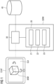
- FIG. 1 1 shows a system 1 for providing a 3D model of an object according to one embodiment.
- the system 1 has a server SERV (as an example of a second computing unit), an interface 30, a user terminal or client CLNT (as an example of a first computing device) and a storage device 40.
- the server SERV is basically designed to calculate a 3D model of a three-dimensional object based on volume data VD describing the three-dimensional object.
- the volume data VD can be provided to the server SERV via the interface 30 from the storage device 40.
- the storage device 40 can be designed as a central or decentralized database.
- the storage device 40 can in particular be part of a server system.
- the storage device 40 can in particular be part of a medical information system such as a hospital information system (an English technical term for this is hospital information system or HIS for short) and/or a PACS system (PACS stands for picture archiving and communication system) and/or or a laboratory information system (LIS).
- the storage device 40 can also be designed as a so-called cloud storage.
- the volume data VD of the three-dimensional object can be stored in the storage device 40.
- the volume data VD represents the three-dimensional object.
- the volume data VD have a three-dimensional data set consisting of a plurality of volume pixels, the so-called voxels.
- One or more geometric and/or physical properties of the three-dimensional object can be encoded in a spatially resolved manner in the volume data VD.
- the voxel values can represent a measure of the local density of the three-dimensional object at the location of the voxel.
- the volume data VD can have been generated by a corresponding imaging method, for example by X-ray fluoroscopy or computer tomography methods.
- the volume data VD may have been generated by a medical imaging process.
- the volume data VD can then represent a part of a patient's body and, for example, show one or more organs of the patient.
- the volume data VD may have been generated by x-ray fluoroscopy, computed tomography (CT), magnetic resonance imaging (MR), ultrasound and/or positron emission tomography (PET).
- CT computed tomography
- MR magnetic resonance imaging
- PET positron emission tomography
- the volume data VD can be formatted in DICOM format, for example.
- DICOM stands for Digital Imaging and Communications in Medicine and describes an open standard for storing and exchanging information in medical image data management.
- Providing the volume data VD can, for example, include loading the volume data VD into a main memory (not shown) of the server SERV.
- further information may be present in the system 1 that is relevant for the generation of the three-dimensional model 3DM.
- these are, for example, specific requirement profiles AP for the generation of the 3D model 3DM, certain user preferences NP regarding the generation of the 3D model, or further information regarding the object to be modeled.
- the latter can be, for example, patient information PI.
- Additional information can be stored in the storage device 40 (or the medical information system) or be provided by a user of the user terminal CLNT.
- the server SERV is designed to calculate a three-dimensional model 3DM of the object shown in the volume data VD based on the volume data VD.
- the server SERV can be designed to take the additional information into account.
- the server SERV can have one or more processors.
- the processors may be implemented as a central processing unit (CPU), a graphics processing unit (GPU), a digital signal processor (DSP), an image processing processor, an integrated circuit (digital or analog), or combinations of the aforementioned components.
- the server SERV can be implemented as a single component or have multiple components that work in parallel or serially.
- the server SERV can have a real or virtual group of computers, such as a cluster or a cloud.
- the server SERV can be designed as a local server or as a cloud server.
- the server SERV is designed, for example, by computer-readable instructions, design and/or hardware in such a way that it can carry out one or more method steps according to embodiments of the invention.
- the server SERV is designed in particular to calculate the 3D model 3DM not directly from the volume data VD, but rather via an intermediate step.
- This intermediate step involves first generating a set S of two-dimensional visualization images VB from the volume data VD.
- a physical rendering method is preferably used, which can be based on the simulation of optical beam paths. This allows very realistic images of the volume data VD to be generated.
- the server SERV is also designed to then calculate the 3D model 3DM from these images. Compared to a direct calculation of the 3D model 3DM from the volume data VD, this has the advantage that imaging effects such as transparency, shading, color bleeding, Occlusion effects etc. can be taken into account.
- a meaningful calculation of a 3D model directly from the VD volume data is often not easily possible, since various tissues are not resolved with sufficient precision by medical imaging processes and must first be identified using a rendering process.
- the 3D model represents a data set that is reduced or compressed compared to the volume data VD and contains the essential properties for viewing the object.
- This can, for example, be a collection of points in 3D space that are connected by various geometric units such as triangles, lines, curved surfaces, etc. and thus characterize the surfaces that are relevant to the viewer.
- an internal structure of the object can be dispensed with.
- the server SERV or its computing unit 20 can have different modules 21, 22, and 23.
- the subdivision of the computing unit 20 into modules 21-23 merely serves to simplify the explanation of the functionality of the computing unit 20 or the server SERV and is not to be understood as limiting.
- the modules 21-23 or their functions can also be combined in one unit.
- the modules 21-23 can in particular also be understood as computer program products or computer program segments, which, when executed in the computing unit 20 or the server SERV, implement one or more of the method steps described below.
- the module 21 can be understood as a configuration module 21.
- the configuration module 21 can implement, host or control a configuration algorithm KA, which is designed to, based on the input data, i.e. the volume data VD and possibly additional information, a parameter set PS for controlling an image synthesis algorithm BSA determined.
- the parameter set PS contains information that causes the image synthesis algorithm BSA to output the set S visualization images VB.
- the configuration algorithm KA may include a trained function.
- the module 22 can be understood as a visualization module 22 or “volume rendering engine”.
- the visualization module 22 can implement, host or control an image synthesis algorithm BSA, which is designed to map the volume data VD onto the visualization image VB or the pixels of the visualization image VB.
- the image synthesis algorithm BSA can have various modules.
- the image synthesis algorithm BSA can include a ray casting module in which the pixels of the visualization images VB are calculated using the ray casting method.
- the image synthesis algorithm BSA can have a path tracing module in which the pixels of the visualization images VB are calculated using the path tracing method.
- individual modules of the BSA image synthesis algorithm can relate to additional imaging effects. These additional imaging effects can include, for example, ambient occlusion effects, shadow effects, translucency effects, color bleeding effects, surface shading, complex camera effects and/or lighting effects due to any ambient lighting conditions, particularly in the case of ray-casting processes.
- the module 23 can be understood as a modeling module 23.
- the modeling module 23 is designed to calculate a 3D model from visualization images VB calculated by the image synthesis algorithm BSA.
- the modeling module 23 can implement, host or control a modeling algorithm MA, which is designed to calculate the 3D model 3DM from the visualization images VB.
- the modeling algorithm MA can implement a photogrammetry method.
- the 3D model 3DM is provided to the user terminal CLNT via the interface 30.
- the user terminal CLNT may have an output device such as a screen designed to display a graphical user interface GUI for displaying various views of the 3D model.
- the user terminal CLNT can have an input device such as a touchscreen, with which the user can select different views of the 3D model.
- the user terminal CLNT may have a computing unit, such as a processor, which is designed to calculate two-dimensional visualizations based on the selected views and the 3D model 3DM.
- the user terminal CLNT is a smartphone or a tablet PC or a laptop or a desktop PC.
- the interface 30 can have one or more individual data interfaces that ensure data exchange between the components SERV, CLNT, 40 of the system 1.
- the one or more data interfaces can have a hardware and/or software interface, for example a PCI bus, a USB interface, a FireWire interface, a ZigBee or a Bluetooth interface.
- the one or more data interfaces may comprise an interface of a communications network, wherein the communications network may comprise a local area network (LAN), for example an intranet or a wide area network (WAN), or an Internet.
- the one or more data interfaces can have a LAN interface or a wireless LAN interface (WLAN or Wi-Fi).
- the interface between the user terminal CLNT and server SERV is an Internet interface and the data transmission between the user terminal CLNT and server SERV takes place via the Internet.
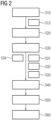
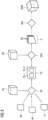
- FIG 2 a schematic flowchart of a method for visualizing a three-dimensional object is shown.
- the order of the process steps is neither limited by the sequence shown nor by the numbering chosen.
- the order of the steps can be swapped if necessary and individual steps can be omitted.
- an associated data flow diagram is shown schematically.
- the method is shown as an example using medical image data as volume data VD. It goes without saying that the method can also be largely applied to any other types of image data.
- a first step S10 is aimed at providing the volume data VD.
- the provision can be realized by retrieving the volume data VD from the storage device 40 and/or loading the volume data VD into the server SERV.
- the volume data VD represents a three-dimensional object. In the example discussed, this is a body part of a patient.
- additional information can be provided for the targeted generation of the set S of the visualization images VB and thus for the targeted calculation of the 3D model 3DM.
- the additional information can include, for example, patient information PI, a requirements profile AP and/or a user preference NP.
- the patient information PI can include, for example, a medical report of the patient, and/or an electronic patient file of the patient and/or a diagnosis task for creating a diagnosis for the patient by a user.
- the patient information PI can thus contain information that is relevant for the visualization and model generation, such as information about a body part to be diagnosed, one or more suspected diagnoses relating to one or more body parts, information about a medical finding, etc.
- the patient information PI includes one or more structured or unstructured text documents containing natural language. Such information can be provided or downloaded from the storage device 40.
- Requirement profiles AP can generally include information about which different individual images are required to generate a specific 3D 3DM model. This can include a number of visualization images VB or an indication of the views to be depicted. Different types of 3DM models can each have different AP requirement profiles. When selecting a 3DM model, the associated requirements profile AP can therefore be selected and provided. Requirement profiles AP can be stored in the server SERV or provided or downloaded from the storage device 40.
- User preferences NP may include general preferred user settings for the calculation of the 3D model 3DM, such as imaging parameters (scene illumination, resolution, available views, transfer functions, etc.) or the type of 3D model 3DM desired by the user.
- User preferences NP can be provided, for example, by the user terminal CLNT.
- user preferences NP can be stored in the server SERV or provided or downloaded from the storage device 40.
- a further step S20 is aimed at providing the image synthesis algorithm BSA.
- the provision can be made by holding and/or calling the image synthesis algorithm BSA in or from any memory (e.g. a storage device 40 of a medical information system or any memory of the server SERV) and/or loading the image synthesis algorithm BSA into the computing unit 20 of the server SERV must be implemented.
- a parameter set PS is determined from the patient information PI, the user preference NP and/or the requirements profile AP.
- the parameter set PS is suitable for using the image synthesis algorithm BSA to generate the set S of visualization images VB, from which a 3D model 3DM can be calculated.
- the parameter set PS can therefore be understood as a set of control commands with which the image synthesis algorithm BSA can be controlled to generate the set S of visualization images VB. Corresponding settings for the image synthesis algorithm BSA can therefore be coded in the parameter set PS.
- the parameter set PS has two different types of parameters. On the one hand, these are “global” parameters that apply to all visualization images VB of a set S. This concerns, for example, the scene illumination, the transfer function, the contrast, the sharpness, a transparency of one or more areas of the volume data VD, a cutting plane through the volume data VD, one or more additional information for display in the visualization images VB, etc. These are “global” parameters summarized in the first parameterization PS-1.
- the parameter set PS also includes a second parameterization PS-2, in which instructions for generating the various views or perspectives for the subsequent calculation of the 3D model 3DM are coded.
- the 3D model 3DM to be calculated can be specified in a substep S31. This can be done automatically based on the volume data VD or the optional patient information PI and/or the optional requirement profile AP. For example, it can be specified that a specific 3D model is to be generated for a specific patient information PI (e.g. a specific report to be created).
- the 3D model to be generated can be automatically selected in step S31 from a plurality of different predetermined 3D models.
- a user of the user terminal can select a specific 3D model 3DM CLNT takes place and is passed on to the server SERV via the user preference NP, for example.
- an automatic segmentation of the volume data VD for the visualization and thus the 3D model 3DM can take place.
- one or more selection organs can first be identified for display in the 3D model 3DM. This can be done, for example, based on the patient information PI. If, for example, the lungs are mentioned in the patient information PI, it can be concluded that the lungs are the selected organ.
- the patient information PI can be analyzed, for example, with a computer linguistic algorithm that is designed to recognize one or more keywords or terms in the patient information PI.
- one or more segmentation masks can be determined for application to the volume data VD. The segmentation masks are designed to segment, i.e. identify, the image data belonging to the selection organ in the volume data VD.
- the parameter set PS can be determined by a correspondingly adapted configuration algorithm KA based on the input data (volume data VD or optionally patient information PI, user preference NP and/or requirement profile AP).
- the configuration algorithm KA can include a computer linguistic algorithm that is designed for the algorithmic processing of natural language in the form of text or speech data.
- the configuration algorithm KA can include a trained function TF, which is designed to generate the parameter set PS based on the input data. In an optional step S34, such a trained function can be provided accordingly.
- step S40 the set S visualization images VB is generated based on the parameter set PS and the volume data VD.
- the volume data VD and the parameter set are used for this purpose PS entered into the image synthesis algorithm BSA.
- a segmentation mask determined in step S30 can be taken into account.
- step S50 the visualization images VD generated in step S40 are used to calculate a 3D model 3DM of the object shown in the volume data VD.
- the visualization images VB are entered into a modeling algorithm MA, which is designed to calculate a 3D model of an object based on various two-dimensional views.
- the modeling algorithm MA converts multiple two-dimensional visualization images VB into the three-dimensional model 3DM.
- the modeling algorithm MA can implement a photogrammetry method.
- the modeling algorithm MA is designed to determine the position and shape of the three-dimensional object from the set S of visualization images VB by image measurement.
- the imaging geometry can be restored at the time the visualization images VB are calculated.
- This restoration can take place, for example, according to the laws of central projection while maintaining complanarity.
- Each image defines a direction to the object point for an imaged point together with the projection center of the respective virtual camera. If the orientation of the virtual camera and the imaging geometry are known, every ray in space can then be described.
- the modeling algorithm MA can bring the two beams to intersect with knowledge of the mutual position (relative orientation) and thus calculate each object point three-dimensionally.
- step S60 the 3D model 3DM is finally provided.
- the 3D model 3DM can be transmitted to the user terminal CLNT or made available for download by the user terminal CLNT.
- This can be made available for download 3D model 3DM, for example, from a corresponding storage device 40 of the medical information system, such as a cloud storage.
- the 3D model 3DM can be provided with a viewing application.
- the viewing application can provide a graphical user interface GUI.
- the user can use the graphical user interface GUI to select and display different views of the 3D model 3DM.
- the views represent (similar to the visualization images VB) two-dimensional “renderings” of three-dimensional source data.
- the viewing application can be activated, for example, on the user terminal CLNT by the user downloading it from an app store and/or running it locally.
- the viewing application can be designed as a web application that is hosted by the server and/or the medical information system.
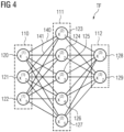
- Figure 4 shows an exemplary representation of a trained function TF, as it can be used in step S30 to determine a parameter set PS.
- the trained function TF receives the volume data VB or optionally the patient information PI, the user preference NP and/or the requirements profile AP as input and outputs the parameter set PS as output, in other words control commands for controlling the visualization module 22 or image synthesis algorithm BSA.
- the trained function TF is designed as a neural network.
- the neural network can also be called artificial neural network, artificial neural network or neural network.
- the neural network 100 includes nodes 120,..., 129 and edges 140,141, each edge 140,141 having a directed connection from a first node 120,...,129 to a second node 120,..., 129 is.
- the first node 120,...,129 and the second node 120,...,129 are different nodes, it is also possible that the first node 120,...,129 and the second node 120,. ..,129 are identical.
- An edge 140,141 from a first node 120,...,129 to a second node 120,...,129 can also be referred to as an incoming edge for the second node and an outgoing edge for the first node 120,...,129 become.
- the neural network 100 responds to input values x (1) 1 , x (1) 2 , x (1) 3 to a plurality of input nodes 120, 121, 122 of the input layer 110.
- the input values x (1) 1 , x (1) 2 , x (1) 3 are applied to produce one or a plurality of outputs x (3) 1 , x (3) 2 .
- the node 120 is connected to the node 123 via an edge 140, for example.
- the node 121 is connected to the node 123 via the edge 141, for example.
- the neural network 100 learns by adjusting the weighting factors w i,j (weights) of the individual nodes based on training data.
- Possible input values x (1) 1 , x (1) 2 , x (1) 3 of the input nodes 120, 121, 122 can, for example, be the individual field sizes ⁇ BC , H ⁇ BC , ⁇ i , H ⁇ i and/or examination information UI ( if available).
- the neural network 100 weights the input values of the input layer 110 based on the learning process.
- the output values of the output layer 112 of the neural network 100 preferably correspond to field information FI, on the basis of which the electric and/or magnetic field on which the signature S is based can be at least partially suppressed.
- the output may occur via a single or a plurality of output nodes x (3) 1 , x (3) 2 in the output layer 112.
- the artificial neural network 100 preferably includes a hidden layer 111 which includes a plurality of nodes x (2) 1 , x (2) 2 , x (2) 3 . Multiple hidden layers can be provided be, where one hidden layer uses output values of another hidden layer as input values.
- the nodes of a hidden layer 111 perform mathematical operations. An output value of a node x (2) 1 , x (2) 2 , x (2) 3 corresponds to a non-linear function f of its input values x (1) 1 , x (1) 2 , x (1) 3 and the Weighting factors w i,j .
- the weighting factor w i,j can in particular be a real number, in particular in the interval of [-1;1] or [0;1].
- the weighting factor w i , j m n denotes the weight of the edge between the i-th node of an m-th layer 110,11,112 and a j-th node of the n-th layer 110,111,112.
- an output value of a node x (2) 1 , x (2) 2 , x (2) 3 is formed as a function f of a node activation, for example a sigmoidal function or a linear ramp function.
- the output values x (2) 1 , x (2) 2 , x (2) 3 are transmitted to the output node(s) 128,129.
- a summation of a weighted multiplication of each output value x (2) 1 , x (2) 2 , x (2) 3 is calculated as a function of the node activation f and thus the output values x (3) 1 , x (3) 2 .
- the neural network TF shown here is a feedforward neural network in which all nodes 111 process the output values of a previous layer in the form of their weighted sum as input values.
- other types of neural networks can also be used, for example feedback networks, in which an input value of a node can also be its output value at the same time.
- the neural network TF can be trained using a supervised learning method to provide the field information FI.
- a well-known procedure is back-propagation, which can be used for all embodiments of the invention.
- the neural network TF is applied to training input data or values and must generate corresponding, previously known training output data or values. Iteratively, mean square errors (MSE) between calculated and expected output values are calculated and individual weighting factors are adjusted until the deviation between calculated and expected output values is below a predetermined threshold.
- MSE mean square errors
- parameter sets PS can be used, which were created by visualization experts for a specific medical context and for specific volume data VD.
- FIG 5 shows an embodiment of a system 200 for training or providing the trained function TF.
- the system 200 includes a processor 210, an interface 220, a working memory 230, a storage device 240 and a database 250.
- the processor 210, the interface 220, the working memory 230 and the storage device 240 can be designed as a computer 290.
- the processor 210 controls the operation of the computer 290 in training the trained function TF.
- the processor 210 can be designed in such a way that it has the in Figure 6 carries out the process steps shown.
- the instructions may be stored in memory 230 or memory device 240 and/or loaded into memory 230 when execution of the instructions is desired.
- the storage device 240 may be configured as a local storage or a remote storage accessible over a network.
- the method steps shown can be carried out using computer program products are defined, which are stored in the main memory 230 and/or the storage device 240.
- the database 250 may be implemented as cloud storage or local storage that communicates with the computer 290 via the wireless or wired interface 220.
- the database 250 can in particular also be part of the computer 290.
- the database 250 serves as an archive for the (training) volume data, additional training information (patient information PI, user preference NP and/or requirement profile AP) and/or associated training parameter sets.
- the database 250 can serve as an archive for one or more trained functions TF.
- FIG. 6 a schematic flowchart of a method for providing a trained function TF for providing a parameter set PS is shown.
- the order of the process steps is neither limited by the sequence shown nor by the numbering chosen.
- the order of the steps can be swapped if necessary and individual steps can be omitted.
- a first step T10 is aimed at providing a trained function TF.
- the trained function TF can be provided to the processor 210 via the interface 220 from the database 250.
- the trained function TF can already be pre-trained, that is, one or more parameters of the trained function TF have already been adapted by the training method described and/or another training method.
- the one or more parameters of the trained function may not yet be adapted using training data; in particular, the one or more parameters may be preset by a constant value and/or by a random value.
- all parameters of the trained function TF cannot yet be adapted using training data; in particular, all parameters can be preset by a constant value and/or by a random value.
- a second step T20 is aimed at providing training input data. Since the trained function TF is intended to provide a parameter set PS in use that matches the respective volume data VD and optionally based on the associated patient information PI, the associated user preference NP and/or the associated requirement profile AP, suitable training input data are training volume data and such optional additional information .
- Step T30 is directed to providing training output data.
- the training output data are training parameter sets PS.
- a training parameter set PS represents the parameter set PS that makes sense for a set of training volume data VD, which leads to a set S of visualization images VB suitable for creating a 3D model 3DM.
- the training parameter sets PS can be provided, for example, by an expert.
- the training input data i.e. training volume data VD and, if necessary, the additional information PI, NP, AP are entered into the trained function TF.
- the trained function TF calculates a parameter set PS for controlling an image synthesis algorithm BSA.
- the parameter set PS calculated in this way is compared with the associated training parameter set PS. Based on this comparison, the trained function TF is then adapted in step T60. This can be done, for example, on the basis of a cost functional that penalizes deviations of the calculated parameter set PS from the associated training parameter set PS. One or more parameters of the trained function TF can then be adjusted in particular in such a way that the cost functional is minimized, for example by means of back propagation (an English technical term is “back propagation”).
- the cost functional can be based on a pairwise difference of control or visualization parameters of the calculated parameter set PS and the associated training parameter set PS are based, for example, on the sum of the squared deviations.
- the comparison is carried out for different pairwise sets of calculated parameter set PS and associated training parameter set PS until a local minimum of the cost functional is reached and the trained function TF works satisfactorily.
Landscapes
- Engineering & Computer Science (AREA)
- Health & Medical Sciences (AREA)
- Physics & Mathematics (AREA)
- Medical Informatics (AREA)
- Public Health (AREA)
- General Physics & Mathematics (AREA)
- Theoretical Computer Science (AREA)
- Primary Health Care (AREA)
- General Health & Medical Sciences (AREA)
- Epidemiology (AREA)
- Computer Graphics (AREA)
- Software Systems (AREA)
- Databases & Information Systems (AREA)
- Pathology (AREA)
- Data Mining & Analysis (AREA)
- Biomedical Technology (AREA)
- Computer Vision & Pattern Recognition (AREA)
- Geometry (AREA)
- Nuclear Medicine, Radiotherapy & Molecular Imaging (AREA)
- Radiology & Medical Imaging (AREA)
- Multimedia (AREA)
- Signal Processing (AREA)
- Processing Or Creating Images (AREA)
- Apparatus For Radiation Diagnosis (AREA)
Priority Applications (3)
| Application Number | Priority Date | Filing Date | Title |
|---|---|---|---|
| EP22179088.4A EP4293626A1 (fr) | 2022-06-15 | 2022-06-15 | Procédé et dispositif de fourniture d'un modèle tridimensionnel d'un objet |
| US18/332,921 US20240020919A1 (en) | 2022-06-15 | 2023-06-12 | Method and apparatus for supplying a three-dimensional model of an object |
| CN202310703135.3A CN117237524A (zh) | 2022-06-15 | 2023-06-14 | 用于提供对象的三维模型的方法和设备 |
Applications Claiming Priority (1)
| Application Number | Priority Date | Filing Date | Title |
|---|---|---|---|
| EP22179088.4A EP4293626A1 (fr) | 2022-06-15 | 2022-06-15 | Procédé et dispositif de fourniture d'un modèle tridimensionnel d'un objet |
Publications (1)
| Publication Number | Publication Date |
|---|---|
| EP4293626A1 true EP4293626A1 (fr) | 2023-12-20 |
Family
ID=82067708
Family Applications (1)
| Application Number | Title | Priority Date | Filing Date |
|---|---|---|---|
| EP22179088.4A Pending EP4293626A1 (fr) | 2022-06-15 | 2022-06-15 | Procédé et dispositif de fourniture d'un modèle tridimensionnel d'un objet |
Country Status (3)
| Country | Link |
|---|---|
| US (1) | US20240020919A1 (fr) |
| EP (1) | EP4293626A1 (fr) |
| CN (1) | CN117237524A (fr) |
Families Citing this family (1)
| Publication number | Priority date | Publication date | Assignee | Title |
|---|---|---|---|---|
| US12519924B2 (en) | 2022-08-31 | 2026-01-06 | Snap Inc. | Multi-perspective augmented reality experience |
Citations (5)
| Publication number | Priority date | Publication date | Assignee | Title |
|---|---|---|---|---|
| US20150138201A1 (en) * | 2013-11-20 | 2015-05-21 | Fovia, Inc. | Volume rendering color mapping on polygonal objects for 3-d printing |
| US20170106597A1 (en) * | 2015-10-14 | 2017-04-20 | General Electric Company | Utilizing depth from ultrasound volume rendering for 3d printing |
| EP3178068B1 (fr) | 2014-09-23 | 2018-09-19 | Siemens Healthcare GmbH | Procédé, dispositifs de visualisation et produit-programme d'ordinateur pour la visualisation d'un objet tridimensionnel |
| US20210150811A1 (en) * | 2019-11-18 | 2021-05-20 | GE Precision Healthcare LLC | System and method for automatic generation of a three-dimensional polygonal model with color mapping from a volume rendering |
| US20210208567A1 (en) * | 2020-01-07 | 2021-07-08 | GE Precision Healthcare LLC | Methods and systems for using three-dimensional (3d) model cuts based on anatomy for three-dimensional (3d) printing |
Family Cites Families (2)
| Publication number | Priority date | Publication date | Assignee | Title |
|---|---|---|---|---|
| US10867061B2 (en) * | 2018-09-28 | 2020-12-15 | Todd R. Collart | System for authorizing rendering of objects in three-dimensional spaces |
| JP2023509514A (ja) * | 2020-01-07 | 2023-03-08 | クリールリー、 インコーポレーテッド | 医用画像分析、診断、重症度分類、意思決定、および/または疾患追跡のためのシステム、方法、およびデバイス |
-
2022
- 2022-06-15 EP EP22179088.4A patent/EP4293626A1/fr active Pending
-
2023
- 2023-06-12 US US18/332,921 patent/US20240020919A1/en active Pending
- 2023-06-14 CN CN202310703135.3A patent/CN117237524A/zh active Pending
Patent Citations (5)
| Publication number | Priority date | Publication date | Assignee | Title |
|---|---|---|---|---|
| US20150138201A1 (en) * | 2013-11-20 | 2015-05-21 | Fovia, Inc. | Volume rendering color mapping on polygonal objects for 3-d printing |
| EP3178068B1 (fr) | 2014-09-23 | 2018-09-19 | Siemens Healthcare GmbH | Procédé, dispositifs de visualisation et produit-programme d'ordinateur pour la visualisation d'un objet tridimensionnel |
| US20170106597A1 (en) * | 2015-10-14 | 2017-04-20 | General Electric Company | Utilizing depth from ultrasound volume rendering for 3d printing |
| US20210150811A1 (en) * | 2019-11-18 | 2021-05-20 | GE Precision Healthcare LLC | System and method for automatic generation of a three-dimensional polygonal model with color mapping from a volume rendering |
| US20210208567A1 (en) * | 2020-01-07 | 2021-07-08 | GE Precision Healthcare LLC | Methods and systems for using three-dimensional (3d) model cuts based on anatomy for three-dimensional (3d) printing |
Non-Patent Citations (5)
| Title |
|---|
| FENG DONG ET AL: "Interacivie visualisation of a distributed library of pathological human organs", 19991118, 18 November 1999 (1999-11-18), pages 17/1 - 17/5, XP006502626 * |
| KAJIYA: "The rendering equation", ACM SIGGRAPH COMPUTER GRAPHICS, vol. 20, no. 4, August 1986 (1986-08-01), pages 143 - 150 |
| LEVOY: "Display of Surfaces from Volume Data", IEEE COMPUTER GRAPHICS AND APPLICATIONS, vol. 8, no. 3, May 1988 (1988-05-01), pages 29 - 37, XP011413670, DOI: 10.1109/38.511 |
| MATTHEW BERGER ET AL: "A Generative Model for Volume Rendering", ARXIV.ORG, CORNELL UNIVERSITY LIBRARY, 201 OLIN LIBRARY CORNELL UNIVERSITY ITHACA, NY 14853, 26 October 2017 (2017-10-26), XP081435113, DOI: 10.1109/TVCG.2018.2816059 * |
| PEI YUCHEN ET AL: "3D Structure Surface Modelling From Volumetric CT Images", 2019 IEEE 16TH INTERNATIONAL SYMPOSIUM ON BIOMEDICAL IMAGING (ISBI 2019), IEEE, 8 April 2019 (2019-04-08), pages 476 - 479, XP033576565, DOI: 10.1109/ISBI.2019.8759432 * |
Also Published As
| Publication number | Publication date |
|---|---|
| US20240020919A1 (en) | 2024-01-18 |
| CN117237524A (zh) | 2023-12-15 |
Similar Documents
| Publication | Publication Date | Title |
|---|---|---|
| DE102019008168A1 (de) | Dynamisches Schätzen von Beleuchtungsparametern für Positionen innerhalb realitätserweiterter Szenen unter Nutzung eines neuronalen Netzwerkes | |
| DE60026197T2 (de) | Detailgerichtete hierarchische Distanzfelder in der Objektmodellierung | |
| DE69924699T2 (de) | Verfahren zur Schaffung von als Oberflächenelemente dargestellten grafischen Objekten | |
| DE102017009910A1 (de) | Bearbeiten von Digitalbildern unter Nutzung eines neuronalen Netzwerkes mit einer netzwerkinternen Erstellungsschicht | |
| DE102017007967A1 (de) | Verarbeiten und rendern eines dreidimensionalen Modells | |
| DE69924230T2 (de) | Verfahren zur Modellierung von durch Oberflächenelemente dargestellten grafischen Objekten | |
| DE19955690A1 (de) | System und Verfahren zur auf einer Volumendarstellung basierenden Segmentation | |
| DE102020213305A1 (de) | Verfahren und Vorrichtung zur Visualisierung von dreidimensionalen Objekten | |
| DE102005008609A1 (de) | Flexible Erzeugung von digital rekonstruierten Röntgenaufnahmen | |
| DE102012107529A1 (de) | Verfahren System zur Navigation, Segmentierung und Extraktion eines dreidimensionalen Bildes | |
| DE102020210030A1 (de) | Verfahren und Vorrichtung zur Visualisierung von dreidimensionalen Objekten | |
| DE112018007236T5 (de) | Verfahren und vorrichtung zum erzeugen eines dreidimensionalen (3d) modells zur rekonstruktion einer 3d-szene | |
| EP2528042A1 (fr) | Procédé et dispositif de remaillage de modèles de polygones en 3D | |
| DE102023127131A1 (de) | Techniken der künstlichen intelligenz zur extrapolation von hdr-panoramen aus ldr-bildern mit geringem blickfeld (fov) | |
| Garcia-Cantero et al. | Neurotessmesh: a tool for the generation and visualization of neuron meshes and adaptive on-the-fly refinement | |
| DE102022100517A1 (de) | Verwenden von intrinsischen funktionen zum schattenentrauschen in raytracinganwendungen | |
| DE102011076878A1 (de) | Verfahren und Vorrichtung zur effizienten Editierung eines dreidimensionalen Volumens mittels Ray Casting | |
| DE102021210435A1 (de) | Verfahren und Vorrichtung zur Visualisierung von dreidimensionalen Objekten | |
| DE102009042326A1 (de) | Interaktive Veränderung der Darstellung eines mittels Volume Rendering dargestellten Objekts | |
| DE102024201496A1 (de) | Verfahren und Systeme zum Bereitstellen einer Bilderfassungsinformation eines medizinischen Bildes | |
| DE112020007352B4 (de) | Führungseinrichtung, programm und führungsverfahren | |
| DE102012203122A1 (de) | Verfahren und System zur Ermittlung eines Begrenzungsflächennetzes | |
| EP4293626A1 (fr) | Procédé et dispositif de fourniture d'un modèle tridimensionnel d'un objet | |
| CN120219640B (zh) | 一种基于超分辨率的乳头保护区三维重建方法及系统 | |
| DE102022119558A1 (de) | Generieren von Schatten für Digitalobjekte innerhalb von Digitalbildern unter Einsatz einer Höhenkarte |
Legal Events
| Date | Code | Title | Description |
|---|---|---|---|
| PUAI | Public reference made under article 153(3) epc to a published international application that has entered the european phase |
Free format text: ORIGINAL CODE: 0009012 |
|
| STAA | Information on the status of an ep patent application or granted ep patent |
Free format text: STATUS: THE APPLICATION HAS BEEN PUBLISHED |
|
| AK | Designated contracting states |
Kind code of ref document: A1 Designated state(s): AL AT BE BG CH CY CZ DE DK EE ES FI FR GB GR HR HU IE IS IT LI LT LU LV MC MK MT NL NO PL PT RO RS SE SI SK SM TR |
|
| RAP1 | Party data changed (applicant data changed or rights of an application transferred) |
Owner name: SIEMENS HEALTHINEERS AG |
|
| STAA | Information on the status of an ep patent application or granted ep patent |
Free format text: STATUS: REQUEST FOR EXAMINATION WAS MADE |
|
| 17P | Request for examination filed |
Effective date: 20240617 |
|
| RBV | Designated contracting states (corrected) |
Designated state(s): AL AT BE BG CH CY CZ DE DK EE ES FI FR GB GR HR HU IE IS IT LI LT LU LV MC MK MT NL NO PL PT RO RS SE SI SK SM TR |