EP4293733A1 - Phosphor, lichtemittierende vorrichtung, beleuchtungsvorrichtung, bildanzeigevorrichtung und fahrzeuganzeigelampe - Google Patents
Phosphor, lichtemittierende vorrichtung, beleuchtungsvorrichtung, bildanzeigevorrichtung und fahrzeuganzeigelampe Download PDFInfo
- Publication number
- EP4293733A1 EP4293733A1 EP22921978.7A EP22921978A EP4293733A1 EP 4293733 A1 EP4293733 A1 EP 4293733A1 EP 22921978 A EP22921978 A EP 22921978A EP 4293733 A1 EP4293733 A1 EP 4293733A1
- Authority
- EP
- European Patent Office
- Prior art keywords
- phosphor
- light
- formula
- group
- emitting device
- Prior art date
- Legal status (The legal status is an assumption and is not a legal conclusion. Google has not performed a legal analysis and makes no representation as to the accuracy of the status listed.)
- Granted
Links
Images



Classifications
-
- C—CHEMISTRY; METALLURGY
- C09—DYES; PAINTS; POLISHES; NATURAL RESINS; ADHESIVES; COMPOSITIONS NOT OTHERWISE PROVIDED FOR; APPLICATIONS OF MATERIALS NOT OTHERWISE PROVIDED FOR
- C09K—MATERIALS FOR MISCELLANEOUS APPLICATIONS, NOT PROVIDED FOR ELSEWHERE
- C09K11/00—Luminescent materials, e.g. electroluminescent or chemiluminescent
- C09K11/08—Luminescent materials, e.g. electroluminescent or chemiluminescent containing inorganic luminescent materials
- C09K11/77—Luminescent materials, e.g. electroluminescent or chemiluminescent containing inorganic luminescent materials containing rare earth metals
- C09K11/7728—Luminescent materials, e.g. electroluminescent or chemiluminescent containing inorganic luminescent materials containing rare earth metals containing europium
- C09K11/77346—Aluminium Nitrides or Aluminium Oxynitrides
-
- C—CHEMISTRY; METALLURGY
- C09—DYES; PAINTS; POLISHES; NATURAL RESINS; ADHESIVES; COMPOSITIONS NOT OTHERWISE PROVIDED FOR; APPLICATIONS OF MATERIALS NOT OTHERWISE PROVIDED FOR
- C09K—MATERIALS FOR MISCELLANEOUS APPLICATIONS, NOT PROVIDED FOR ELSEWHERE
- C09K11/00—Luminescent materials, e.g. electroluminescent or chemiluminescent
- C09K11/08—Luminescent materials, e.g. electroluminescent or chemiluminescent containing inorganic luminescent materials
- C09K11/77—Luminescent materials, e.g. electroluminescent or chemiluminescent containing inorganic luminescent materials containing rare earth metals
-
- B—PERFORMING OPERATIONS; TRANSPORTING
- B60—VEHICLES IN GENERAL
- B60Q—ARRANGEMENT OF SIGNALLING OR LIGHTING DEVICES, THE MOUNTING OR SUPPORTING THEREOF OR CIRCUITS THEREFOR, FOR VEHICLES IN GENERAL
- B60Q1/00—Arrangement of optical signalling or lighting devices, the mounting or supporting thereof or circuits therefor
-
- C—CHEMISTRY; METALLURGY
- C09—DYES; PAINTS; POLISHES; NATURAL RESINS; ADHESIVES; COMPOSITIONS NOT OTHERWISE PROVIDED FOR; APPLICATIONS OF MATERIALS NOT OTHERWISE PROVIDED FOR
- C09K—MATERIALS FOR MISCELLANEOUS APPLICATIONS, NOT PROVIDED FOR ELSEWHERE
- C09K11/00—Luminescent materials, e.g. electroluminescent or chemiluminescent
- C09K11/08—Luminescent materials, e.g. electroluminescent or chemiluminescent containing inorganic luminescent materials
- C09K11/0883—Arsenides; Nitrides; Phosphides
-
- C—CHEMISTRY; METALLURGY
- C09—DYES; PAINTS; POLISHES; NATURAL RESINS; ADHESIVES; COMPOSITIONS NOT OTHERWISE PROVIDED FOR; APPLICATIONS OF MATERIALS NOT OTHERWISE PROVIDED FOR
- C09K—MATERIALS FOR MISCELLANEOUS APPLICATIONS, NOT PROVIDED FOR ELSEWHERE
- C09K11/00—Luminescent materials, e.g. electroluminescent or chemiluminescent
- C09K11/08—Luminescent materials, e.g. electroluminescent or chemiluminescent containing inorganic luminescent materials
- C09K11/77—Luminescent materials, e.g. electroluminescent or chemiluminescent containing inorganic luminescent materials containing rare earth metals
- C09K11/7706—Aluminates
-
- C—CHEMISTRY; METALLURGY
- C09—DYES; PAINTS; POLISHES; NATURAL RESINS; ADHESIVES; COMPOSITIONS NOT OTHERWISE PROVIDED FOR; APPLICATIONS OF MATERIALS NOT OTHERWISE PROVIDED FOR
- C09K—MATERIALS FOR MISCELLANEOUS APPLICATIONS, NOT PROVIDED FOR ELSEWHERE
- C09K11/00—Luminescent materials, e.g. electroluminescent or chemiluminescent
- C09K11/08—Luminescent materials, e.g. electroluminescent or chemiluminescent containing inorganic luminescent materials
- C09K11/77—Luminescent materials, e.g. electroluminescent or chemiluminescent containing inorganic luminescent materials containing rare earth metals
- C09K11/7728—Luminescent materials, e.g. electroluminescent or chemiluminescent containing inorganic luminescent materials containing rare earth metals containing europium
-
- C—CHEMISTRY; METALLURGY
- C09—DYES; PAINTS; POLISHES; NATURAL RESINS; ADHESIVES; COMPOSITIONS NOT OTHERWISE PROVIDED FOR; APPLICATIONS OF MATERIALS NOT OTHERWISE PROVIDED FOR
- C09K—MATERIALS FOR MISCELLANEOUS APPLICATIONS, NOT PROVIDED FOR ELSEWHERE
- C09K11/00—Luminescent materials, e.g. electroluminescent or chemiluminescent
- C09K11/08—Luminescent materials, e.g. electroluminescent or chemiluminescent containing inorganic luminescent materials
- C09K11/77—Luminescent materials, e.g. electroluminescent or chemiluminescent containing inorganic luminescent materials containing rare earth metals
- C09K11/7728—Luminescent materials, e.g. electroluminescent or chemiluminescent containing inorganic luminescent materials containing rare earth metals containing europium
- C09K11/77348—Silicon Aluminium Nitrides or Silicon Aluminium Oxynitrides
-
- F—MECHANICAL ENGINEERING; LIGHTING; HEATING; WEAPONS; BLASTING
- F21—LIGHTING
- F21S—NON-PORTABLE LIGHTING DEVICES; SYSTEMS THEREOF; VEHICLE LIGHTING DEVICES SPECIALLY ADAPTED FOR VEHICLE EXTERIORS
- F21S41/00—Illuminating devices specially adapted for vehicle exteriors, e.g. headlamps
- F21S41/10—Illuminating devices specially adapted for vehicle exteriors, e.g. headlamps characterised by the light source
- F21S41/14—Illuminating devices specially adapted for vehicle exteriors, e.g. headlamps characterised by the light source characterised by the type of light source
- F21S41/141—Light emitting diodes [LED]
-
- F—MECHANICAL ENGINEERING; LIGHTING; HEATING; WEAPONS; BLASTING
- F21—LIGHTING
- F21S—NON-PORTABLE LIGHTING DEVICES; SYSTEMS THEREOF; VEHICLE LIGHTING DEVICES SPECIALLY ADAPTED FOR VEHICLE EXTERIORS
- F21S43/00—Signalling devices specially adapted for vehicle exteriors, e.g. brake lamps, direction indicator lights or reversing lights
- F21S43/10—Signalling devices specially adapted for vehicle exteriors, e.g. brake lamps, direction indicator lights or reversing lights characterised by the light source
- F21S43/13—Signalling devices specially adapted for vehicle exteriors, e.g. brake lamps, direction indicator lights or reversing lights characterised by the light source characterised by the type of light source
- F21S43/14—Light emitting diodes [LED]
-
- F—MECHANICAL ENGINEERING; LIGHTING; HEATING; WEAPONS; BLASTING
- F21—LIGHTING
- F21S—NON-PORTABLE LIGHTING DEVICES; SYSTEMS THEREOF; VEHICLE LIGHTING DEVICES SPECIALLY ADAPTED FOR VEHICLE EXTERIORS
- F21S43/00—Signalling devices specially adapted for vehicle exteriors, e.g. brake lamps, direction indicator lights or reversing lights
- F21S43/10—Signalling devices specially adapted for vehicle exteriors, e.g. brake lamps, direction indicator lights or reversing lights characterised by the light source
- F21S43/13—Signalling devices specially adapted for vehicle exteriors, e.g. brake lamps, direction indicator lights or reversing lights characterised by the light source characterised by the type of light source
- F21S43/16—Light sources where the light is generated by photoluminescent material spaced from a primary light generating element
-
- F—MECHANICAL ENGINEERING; LIGHTING; HEATING; WEAPONS; BLASTING
- F21—LIGHTING
- F21V—FUNCTIONAL FEATURES OR DETAILS OF LIGHTING DEVICES OR SYSTEMS THEREOF; STRUCTURAL COMBINATIONS OF LIGHTING DEVICES WITH OTHER ARTICLES, NOT OTHERWISE PROVIDED FOR
- F21V9/00—Elements for modifying spectral properties, polarisation or intensity of the light emitted, e.g. filters
- F21V9/30—Elements containing photoluminescent material distinct from or spaced from the light source
- F21V9/38—Combination of two or more photoluminescent elements of different materials
-
- H—ELECTRICITY
- H05—ELECTRIC TECHNIQUES NOT OTHERWISE PROVIDED FOR
- H05B—ELECTRIC HEATING; ELECTRIC LIGHT SOURCES NOT OTHERWISE PROVIDED FOR; CIRCUIT ARRANGEMENTS FOR ELECTRIC LIGHT SOURCES, IN GENERAL
- H05B33/00—Electroluminescent light sources
- H05B33/12—Light sources with substantially two-dimensional [2D] radiating surfaces
- H05B33/14—Light sources with substantially two-dimensional [2D] radiating surfaces characterised by the chemical or physical composition or the arrangement of the electroluminescent material, or by the simultaneous addition of the electroluminescent material in or onto the light source
-
- H—ELECTRICITY
- H10—SEMICONDUCTOR DEVICES; ELECTRIC SOLID-STATE DEVICES NOT OTHERWISE PROVIDED FOR
- H10H—INORGANIC LIGHT-EMITTING SEMICONDUCTOR DEVICES HAVING POTENTIAL BARRIERS
- H10H20/00—Individual inorganic light-emitting semiconductor devices having potential barriers, e.g. light-emitting diodes [LED]
- H10H20/80—Constructional details
- H10H20/85—Packages
- H10H20/851—Wavelength conversion means
-
- H—ELECTRICITY
- H10—SEMICONDUCTOR DEVICES; ELECTRIC SOLID-STATE DEVICES NOT OTHERWISE PROVIDED FOR
- H10H—INORGANIC LIGHT-EMITTING SEMICONDUCTOR DEVICES HAVING POTENTIAL BARRIERS
- H10H20/00—Individual inorganic light-emitting semiconductor devices having potential barriers, e.g. light-emitting diodes [LED]
- H10H20/80—Constructional details
- H10H20/85—Packages
- H10H20/851—Wavelength conversion means
- H10H20/8511—Wavelength conversion means characterised by their material, e.g. binder
- H10H20/8512—Wavelength conversion materials
-
- H—ELECTRICITY
- H10—SEMICONDUCTOR DEVICES; ELECTRIC SOLID-STATE DEVICES NOT OTHERWISE PROVIDED FOR
- H10H—INORGANIC LIGHT-EMITTING SEMICONDUCTOR DEVICES HAVING POTENTIAL BARRIERS
- H10H20/00—Individual inorganic light-emitting semiconductor devices having potential barriers, e.g. light-emitting diodes [LED]
- H10H20/80—Constructional details
- H10H20/85—Packages
- H10H20/851—Wavelength conversion means
- H10H20/8511—Wavelength conversion means characterised by their material, e.g. binder
- H10H20/8512—Wavelength conversion materials
- H10H20/8513—Wavelength conversion materials having two or more wavelength conversion materials
-
- F—MECHANICAL ENGINEERING; LIGHTING; HEATING; WEAPONS; BLASTING
- F21—LIGHTING
- F21W—INDEXING SCHEME ASSOCIATED WITH SUBCLASSES F21K, F21L, F21S and F21V, RELATING TO USES OR APPLICATIONS OF LIGHTING DEVICES OR SYSTEMS
- F21W2103/00—Exterior vehicle lighting devices for signalling purposes
- F21W2103/35—Brake lights
-
- F—MECHANICAL ENGINEERING; LIGHTING; HEATING; WEAPONS; BLASTING
- F21—LIGHTING
- F21W—INDEXING SCHEME ASSOCIATED WITH SUBCLASSES F21K, F21L, F21S and F21V, RELATING TO USES OR APPLICATIONS OF LIGHTING DEVICES OR SYSTEMS
- F21W2107/00—Use or application of lighting devices on or in particular types of vehicles
- F21W2107/10—Use or application of lighting devices on or in particular types of vehicles for land vehicles
-
- F—MECHANICAL ENGINEERING; LIGHTING; HEATING; WEAPONS; BLASTING
- F21—LIGHTING
- F21Y—INDEXING SCHEME ASSOCIATED WITH SUBCLASSES F21K, F21L, F21S and F21V, RELATING TO THE FORM OR THE KIND OF THE LIGHT SOURCES OR OF THE COLOUR OF THE LIGHT EMITTED
- F21Y2115/00—Light-generating elements of semiconductor light sources
- F21Y2115/10—Light-emitting diodes [LED]
-
- H—ELECTRICITY
- H10—SEMICONDUCTOR DEVICES; ELECTRIC SOLID-STATE DEVICES NOT OTHERWISE PROVIDED FOR
- H10H—INORGANIC LIGHT-EMITTING SEMICONDUCTOR DEVICES HAVING POTENTIAL BARRIERS
- H10H20/00—Individual inorganic light-emitting semiconductor devices having potential barriers, e.g. light-emitting diodes [LED]
- H10H20/80—Constructional details
- H10H20/81—Bodies
- H10H20/822—Materials of the light-emitting regions
- H10H20/824—Materials of the light-emitting regions comprising only Group III-V materials, e.g. GaP
- H10H20/825—Materials of the light-emitting regions comprising only Group III-V materials, e.g. GaP containing nitrogen, e.g. GaN
-
- H—ELECTRICITY
- H10—SEMICONDUCTOR DEVICES; ELECTRIC SOLID-STATE DEVICES NOT OTHERWISE PROVIDED FOR
- H10H—INORGANIC LIGHT-EMITTING SEMICONDUCTOR DEVICES HAVING POTENTIAL BARRIERS
- H10H20/00—Individual inorganic light-emitting semiconductor devices having potential barriers, e.g. light-emitting diodes [LED]
- H10H20/80—Constructional details
- H10H20/85—Packages
- H10H20/855—Optical field-shaping means, e.g. lenses
Definitions
- the present invention relates to a phosphor, a light-emitting device, an illumination device, an image display device, and an indicator lamp for a vehicle.
- the LEDs used in these cases are white light-emitting LEDs in which a phosphor is arranged on an LED chip that emits light in a blue or near ultraviolet wavelength.
- a red phosphor that is used in a light-emitting device As a red phosphor that is used in a light-emitting device, a KSF phosphor represented by the general formulas K 2 (Si, Ti)F 6 :Mn and K 2 Si 1-x Na x Al x F 6 :Mn (0 ⁇ x ⁇ 1), an S/CASN phosphor represented by the general formula (Sr, Ca)AlSiN 3 :Eu, and the like are known examples, but the KSF phosphor is harmful as a Mn-activated compound and so a phosphor that is better for humans and the environment is sought.
- S/CASN phosphors have comparatively broad full widths at half maximum (in other words, FWHM or spectral half peak width) of about 80 nm-90 nm and an emission wavelength region is likely to include a wavelength range with low relative luminous efficiency, and therefore in terms of improving conversion efficiency, a red phosphor with a narrower full width at half maximum is sought.
- a phosphor represented by the composition formula SrLiAl 3 N 4 :Eu is disclosed in an embodiment in Patent Literature 1, for example, as a red phosphor that can be applied to recent light-emitting devices.
- Patent Literature 1 Japanese Patent No. 6335884
- Patent Literature 1 the emission intensity of the phosphor described in Patent Literature 1 is unclear, and a phosphor with more favorable emission intensity and a light-emitting device with favorable conversion efficiency are sought.
- the present invention takes as an objective to provide a light-emitting device, an illumination device, an image display device, and/or an indicator lamp for a vehicle having favorable color rendering, color reproducibility and/or favorable conversion efficiency.
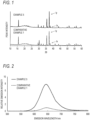
- a phosphor or a light-emitting device comprising the phosphor, that includes a crystal phase represented by a specific composition and in which, in a powder X-ray diffraction spectrum, the intensity of a peak for a heterogeneous phase where 2 ⁇ is in a specific region and the intensity of a peak for the crystal phase represented by the specific composition that is in a different specific region are in a ratio that is equal to or less than a prescribed value, and have perfected the present invention.
- some non-limited embodiments of the present invention are shown below.
- a light-emitting device an illumination device, an image display device, and an indicator lamp for a vehicle having favorable color rendering, color reproducibility, and/or favorable conversion efficiency can be provided.
- the present invention is described by way of embodiments and illustrative examples; however, the present invention is not limited to the following embodiments, illustrative examples, or the like, and can be implemented by making any desired modification within a scope that does not exceed the substance of the present invention.
- composition formulas of phosphors in the present specification signifies a range containing the numerical values noted before and after the "-" as a lower limit value and an upper limit value.
- end of each composition formula is represented by a comma (,).
- a plurality of elements are listed separated by a comma (,) this indicates that one or two or more of the listed elements may be contained in any combination and composition.
- composition formula "(Ca, Sr, Ba)Al 2 O 4 :Eu” inclusively indicates all of “CaAl 2 O 4 :Eu”, “SrAl 2 O 4 :Eu”, “BaAl 2 O 4 :Eu”, “Ca 1-x Sr x Al 2 O 4 :Eu”, “Sr 1-x Ba x Al 2 O 4: Eu”, “Ca 1-x Ba x Al 2 O 4 :Eu”, and "Ca 1-x-y Sr x Ba y Al 2 O 4 :Eu" (where 0 ⁇ x ⁇ 1, 0 ⁇ y ⁇ 1, and 0 ⁇ x + y ⁇ 1 in the formula).
- the present invention is a light-emitting device comprising the phosphor [1] of the present embodiment.
- Eu europium
- Ce cerium
- Pr praseodymium
- Nd neodymium
- Sm samarium
- Tb terbium
- Dy dysprosium
- Ho holmium
- Er erbium
- Tm thulium
- Yb ytterbium
- Re preferably includes one or more elements selected from a group consisting of Eu, Ce, Pr, Tb, and Dy, more preferably includes Eu, still more preferably 80 mol% or more of Re is Eu, and further still more preferably Re is Eu.
- MA includes one or more elements selected from a group consisting of calcium (Ca), strontium (Sr), barium (Ba), sodium (Na), potassium (K), yttrium (Y), gadolinium (Gd), and lanthanum (La), preferably includes one or more elements selected from a group consisting of Ca, Sr, and Ba, and more preferably MA includes Sr.
- a group consisting of calcium (Ca), strontium (Sr), barium (Ba), sodium (Na), potassium (K), yttrium (Y), gadolinium (Gd), and lanthanum (La) preferably includes one or more elements selected from a group consisting of Ca, Sr, and Ba, and more preferably MA includes Sr.
- 80 mol% or more of MA is constituted by the above-noted preferred elements, and more preferably MA is constituted by the above-noted preferred elements.
- MB includes one or more elements selected from a group consisting of lithium (Li), magnesium (Mg), and zinc (Zn), preferably includes Li, more preferably 80 mol% or more of MB is Li, and still more preferably MB is Li.
- MC includes one or more elements selected from a group consisting of aluminum (Al), silicon (Si), gallium (Ga), indium (In), and scandium (Sc), preferably includes Al, Ga, or Si, more preferably includes one or more elements selected from a group consisting of Al and Ga, still more preferably 80 mol% or more of MC is constituted by one or more elements selected from a group consisting of Al and Ga, especially preferably 90 mol% or more of MC is constituted by one or more elements selected from a group consisting of Al and Ga, and most preferably MC is constituted by one or more elements selected from a group consisting of Al and Ga.
- 80 mol% or more of MC is Al, preferably 90 mol% or more, more preferably 95 mol% or more, and still more preferably 98 mol% or more.
- 80 mol% or more of MC being Al, a red phosphor exhibiting a similar emission peak wavelength and emission intensity as existing red phosphors such as S/CASN and with a narrow full width at half maximum can be provided, and by using such a red phosphor, a light-emitting device can be provided that has superior color rendering or color reproducibility while maintaining conversion efficiency (Im/W) similar to or better than the conventional.
- N represents nitrogen.
- N may be partially substituted with oxygen (O) in order to maintain the charge balance of the overall crystal phase, or in order to adjust the emission peak wavelength.
- X includes one or more elements selected from a group consisting of fluorine (F), chlorine (Cl), bromine (Br), and iodine (I). That is, in a specific embodiment, in terms of stabilization of a crystal structure and maintaining a charge balance for the entire phosphor, a portion of N may be substituted with the above-mentioned halogen elements represented by X.
- Formula [1] includes cases where a component other than those specified above is included in trace amounts unavoidably, unintentionally, or deriving from trace additive components or the like.
- Examples of a component other than those specified above include an element having an element number that is one different from an element that was intentionally added, an element of the same group as an element that was intentionally added, a rare earth element different from a rare earth element that was intentionally added, and a halogen element when a halogen compound was used for an Re raw material, an element that may generally be included in various other raw materials as an impurity, or the like.
- An example of a case where a component other than those specified above is included unavoidably or unintentionally may be, for example, a case where the component derives from an impurity in the raw material and where the component is introduced in a manufacturing process such as a pulverization step or synthesis step.
- examples of the trace additive component may include a reaction assistant, Re raw material, and the like.
- a, b, c, d, e, and x respectively indicate molar content of MA, MB, MC, N, X, and Re contained in a phosphor.
- the value of a is ordinarily 0.6 or more, preferably 0.7 or more, more preferably 0.8 or more, and still more preferably 0.9 or more, and is ordinarily 1.4 or less, preferably 1.3 or less, more preferably 1.2 or less, and still more preferably 1.1 or less.
- the value of b is ordinarily 0.6 or more, preferably 0.7 or more, more preferably 0.8 or more, and still more preferably 0.9 or more, and is ordinarily 1.4 or less, preferably 1.3 or less, more preferably 1.2 or less, and still more preferably 1.1 or less.
- c is ordinarily 2.1 or more, preferably 2.4 or more, more preferably 2.6 or more, and still more preferably 2.8 or more, and is ordinarily 3.9 or less, preferably 3.6 or less, more preferably 3.4 or less, and still more preferably 3.2 or less.
- d is ordinarily 3 or more, preferably 3.2 or more, more preferably 3.4 or more, still more preferably 3.6 or more, and even more preferably 3.8 or more, and is ordinarily 5 or less, preferably 4.8 or less, more preferably 4.6 or less, still more preferably 4.4 or less, and even more preferably 4.2 or less.
- e is not particularly limited, but is ordinarily 0 or more, and is ordinarily 0.2 or less, preferably 0.1 or less, more preferably 0.06 or less, still more preferably 0.04 or less, and even more preferably 0.02 or less.
- the value of x is ordinarily a value greater than 0, preferably 0.0001 or more, and more preferably 0.001 or more, and is ordinarily 0.2 or less, preferably 0.15 or less, more preferably 0.12 or less, still more preferably 0.1 or less, and even more preferably 0.08 or less.
- a phosphor having favorable emission intensity can be obtained
- Re can be favorably incorporated in a crystal and a phosphor can be obtained that readily functions as an emission center.
- b + c is ordinarily 3.1 or more, preferably 3.4 or more, and more preferably 3.7 or more, and is ordinarily 4.9 or less, preferably 4.6 or less, and more preferably 4.3 or less.
- d + e is ordinarily 3.2 or more, preferably 3.4 or more, and more preferably 3.7 or more, and is ordinarily 5.0 or less, preferably 4.6 or less, and more preferably 4.3 or less.
- the resulting phosphor has a favorable emission peak wavelength and full width at half maximum of an emission spectrum, which is preferred.
- a method of specifying an elemental composition of the phosphor is not particularly limited, and can be found with a routine method.
- specification can be performed with GD-MS, ICP spectroscopy, an energy-dispersive X-ray spectrometer (EDX), or the like.
- the present invention is a light-emitting device comprising the phosphor [2] of the present embodiment.
- the value of y in formula [2] is greater than 0.0, and is ordinarily 0.01 or more, preferably 0.015 or more, more preferably 0.03 or more, still more preferably 0.05 or more, and especially preferably 0.10 or more, and is ordinarily 1.00 or less, preferably 0.70 or less, more preferably 0.50 or less, still more preferably 0.30 or less, and especially preferably 0.25 or less.
- the emission peak wavelength of the phosphor is shortened, and by using such a phosphor, a light-emitting device can be provided having favorable color rendering or color reproducibility.
- a phosphor having favorable emission intensity can be obtained, and by using such a phosphor, a light-emitting device can be provided having favorable conversion efficiency.
- the value of y can be adjusted as appropriate in order to obtain the desired emission intensity and emission peak wavelength for an objective.
- the particle size of the crystal phase of the phosphor according to the present embodiment is ordinarily 2 ⁇ m or more and 35 ⁇ m or less for a volume median particle size, the lower limit value is preferably 3 ⁇ m, more preferably 4 ⁇ m, and still more preferably 5 ⁇ m, and the upper limit value is preferably 30 ⁇ m or less, more preferably 25 ⁇ m or less, still more preferably 20 ⁇ m, and especially preferably 15 ⁇ m.
- the volume median particle size being equal to or greater than the above-noted lower limit is preferable in terms of improving light emission characteristics the crystal phase exhibits in an LED package, and the volume median particle size being equal to or less than the above-noted upper limit is preferable in terms of the crystal phase being able to avoid obstructing a nozzle in an LED package manufacturing step.
- the volume median particle size of the crystal phase of a phosphor can be measured with a technique known to those skilled in the art, but in a preferable embodiment, for example, it can be measured with laser diffraction particle size analyzer.
- the volume median particle size (d 50 ) is defined as the size of the particle when the cumulative number of particles which is counted sequentially from the smallest one becomes half of the total number.
- a crystal system (space group) of the phosphor of the present embodiment is preferably P-1. So long as a statistically average structure exhibits a repeating period of the above-noted length in a range that may be demarcated by powder X-ray diffraction or single crystal X-ray diffraction, the space group of the phosphor of the present embodiment is not particularly limited, but preferably belongs to #2, which is based on "International Tables for Crystallography (third, revised edition), Volume A, Space-group Symmetry".
- the space group can be found according to a routine method, for example with electron beam diffraction, X-ray diffraction structure analysis using powder or single crystal, neutron beam diffraction structure analysis, and the like.
- the relative intensity Ix/Iy of Ix where Iy is treated as 1 is preferably 0.140 or less, more preferably 0.120 or less, still more preferably 0.110 or less, even more preferably 0.080 or less, especially preferably 0.060 or less, and most especially preferably 0.040 or less, and is ordinarily 0 or more, but the smaller the better.
- Ix/Iy being equal to or less than the above-noted upper limit, a phosphor has high phase purity and a narrow full width at half maximum (FWHM), and therefore emission efficiency of a light-emitting device improves.
- the phosphor of the present embodiment has a minimum reflectance (hereafter also denoted as A%) in a prescribed wavelength region that is ordinarily 20% or more, and the prescribed wavelength region is a region from the emission peak wavelength of the phosphor to 800 nm.
- the minimum reflectance is preferably 25% or more, more preferably 30% or more, still more preferably 35% or more, especially preferably 50% or more, more especially preferably 60% or more, and extremely preferably 70% or more.
- the upper limit of the reflectance is not particularly limited, but the higher the better, and is ordinarily 100% or less.
- a red phosphor having superior emission intensity or quantum efficiency can be provided, and by using such a phosphor, a light-emitting device having favorable conversion efficiency can be provided.
- the prescribed wavelength region associated with the reflectance A (%) of the phosphor of the present embodiment is a wavelength region from the emission peak wavelength to 800 nm. Reasons for selecting the above-noted wavelength region when stipulating the reflectance of the phosphor of the present embodiment are described below.
- the specific wavelength region is preferably a wavelength belonging to a wavelength region different from an excitation spectrum region.
- the specific wavelength region is preferably a wavelength in a wavelength region equal to or greater than the emission peak wavelength and equal to or less than an end portion of a long-wavelength side of the emission spectrum.
- a wavelength equal to or greater than the emission peak wavelength and equal to or less than 900 nm can ordinarily be selected as the specific wavelength region, and the upper limit is preferably 800 nm or less and more preferably 780 nm or less.
- the wavelength region can occupy any wavelength region that is equal to or greater than the lower limit and equal to or less than the upper limit noted above.
- the wavelength region of excitation spectrum of the phosphor of the present embodiment is primarily 300 nm-520 nm, but absorption may occur near 600 nm as well. In this example, it is inappropriate to define the body color of the phosphor based only on the reflectance of the wavelength region of the excitation spectrum because, in that case, the phosphor absorbs incident light and reflectance is influenced by the absorption rate.
- the body color of the phosphor can be accurately defined by reflectance of the wavelength region that is little affected by absorption by the phosphor, or by employing a parameter related to this reflectance.
- the value of [A - B] for the difference from the reflectance A (%) is preferably -1.5 points or more, more preferably 0.0 points or more, still more preferably 3.0 points or more, and especially preferably 4.0 points or more.
- the upper limit of [A - B] is not particularly limited, but is ordinarily 50.0 points or less.
- the wavelength regions associated with the reflectances A (%) and B (%) are consecutive, and therefore it is highly likely that A (%) and B (%) are comparatively close values, and as a result, defining the phosphor by comparison of A (%) and B (%), rather than B (%) alone, may be considered preferable.
- the value of [A - C] for the difference from the reflectance A (%) is preferably 0.0 points or more, more preferably 2.0 points or more, still more preferably 5.0 points or more, especially preferably 10.0 points or more, more especially preferably 15.0 points or more, and extremely preferably 20.0 points or more.
- the upper limit of [A - C] is not particularly limited, but is ordinarily 50.0 points or less.
- the value of C/A for the ratio to the reflectance A (%) is preferably 1.05 or less, more preferably 1.00 or less, still more preferably 0.90 or less, especially preferably 0.80 or less, and more especially preferably 0.75 or less.
- the lower limit of C/A is not particularly limited, but is ordinarily 0.0 or more.
- C/A When the value of C/A is equal to or less than the above-noted upper limit, a phosphor having high emission intensity can be obtained, and by using such a phosphor, a light-emitting device having high conversion efficiency can be provided.
- a phosphor with high absorption that does not contribute to emission due to impurities or the like tends to have reflectance that decreases overall in a broad wavelength region, and therefore from the above-noted perspective, when specifying a phosphor, defining the phosphor by comparison of A (%) and C (%), rather than C (%) alone, may be considered preferable.
- the phosphor according to the present embodiment is excited by irradiating the phosphor with light having a suitable wavelength and gives off a red light exhibiting a favorable emission peak wavelength and full width at half maximum (FWHM) in the emission spectrum.
- FWHM full width at half maximum
- the phosphor of the present embodiment has an excitation peak in a wavelength range of 270 nm or more ordinarily, preferably 300 nm or more, more preferably 320 nm or more, still more preferably 350 nm or more, and especially preferably 400 nm or more, and ordinarily 500 nm or less, preferably 480 nm or less, and more preferably 460 nm or less. That is, the phosphor is excited by light in a region from ultraviolet to blue.
- the phosphor of the present embodiment has a peak wavelength in the emission spectrum of 620 nm or more ordinarily, preferably 625 nm or more, and more preferably 630 nm or more.
- the peak wavelength in the emission spectrum is ordinarily 670 nm or less, preferably 660 nm or less, and more preferably 655 nm or less.
- the color of the emitted light is a favorable red color, and by using this, a light-emitting device can be provided having good color rendering or color reproducibility.
- a light-emitting device can be provided having favorable luminous efficiency of the red color, and favorable luminous efficacy in Im/W.
- Phosphors having different peak wavelengths according to usage can be used in the light-emitting device.
- a method for obtaining phosphors with different peak wavelengths is not particularly limited, and can be achieved by changing the configuration of the MC element, as an example of one method.
- a phosphor having a long emission peak wavelength can be obtained by using Al for MC in formula [1] and increasing the proportion of Al.
- the emission peak wavelength is preferably 640 nm or more, and more preferably 645 nm or more, and is ordinarily 670 nm or less, and preferably 660 nm or less.
- a phosphor in another embodiment, can be obtained that has a relatively short emission peak wavelength by providing a phosphor that includes a crystal phase having a composition represented by formula [2] using MC' (Al) and an MD element.
- the emission peak wavelength is ordinarily 615 nm or more, preferably 620 nm or more, more preferably 625 nm or more, and still more preferably 630 nm or more, and is ordinarily 660 nm or less, preferably 645 nm or less, and more preferably 640 nm or less.
- a light-emitting device having good color rendering or color reproducibility can be obtained by providing a phosphor having an emission wavelength in the above-noted range.
- the phosphor of the present embodiment has a full width at half maximum of the emission peak in the emission spectrum that is ordinarily 80 nm or less, preferably 70 nm or less, more preferably 60 nm or less, still more preferably 55 nm or less, and especially preferably 50 nm or less, and is ordinarily 10 nm or more.
- a color reproduction range of an image display device such as a liquid crystal display can be broadened without reducing color purity by using the phosphor by having the full width at half maximum of the emission peak within the above-noted range.
- a phosphor having relatively high luminous efficiency of the emission wavelength region can be obtained by having the emission peak wavelength and the full width at half maximum equal to or less than the above-noted upper limits, and a light-emitting device having high conversion efficiency can be provided by using such a phosphor in a light-emitting device.
- a GaN type LED for example, can be used to excite the phosphor with light of around 450 nm wavelength.
- the emission spectrum of the phosphor can be measured, and the emission peak wavelength, peak relative intensity, and peak full width at half maximum thereof be calculated, using a commercially-available spectrometry device such as a fluorescence spectrophotometer comprising a generic photodetector and a light source having an emission wavelength of 300-400 nm, such as a commercially available xenon lamp, for example.
- the phosphor of the present embodiment can be synthesized by mixing and heating raw materials of each element comprising the phosphor such that the proportions of each element fulfill formula [1] or [2].
- each element (MA, MB, MC, MC', MD, and Re) are not particularly limited, and examples may include the element alone, an oxide, a nitride, a hydroxide, a chloride, a halide such as fluoride, an inorganic salt such as sulfate, nitrate, or phosphate, an organic salt such as acetate, and the like. Besides these, a compound containing two or more of the element groups may be used. In addition, each compound may also be a hydrate or the like.
- a method of acquiring each of the raw materials is not particularly limited and can employ purchasing commercially available materials.
- the purity of each of the raw materials is not particularly limited, but in terms of strict adherence to element ratios and avoiding the occurrence of a heterogeneous phase due to an impurity, higher purities are more preferred, ordinarily 90 mol% or more, preferably 95 mol% or more, more preferably 97 mol% or more, and still more preferably 99 mol% or more, and the upper limit is not particularly limited, but is ordinarily 100 mol% or less, and impurities that are unavoidably mixed in may be included.
- the oxygen element (O), nitrogen element (N), and halogen element (X) can be supplied using an oxide, nitride, and halide or the like as the raw material for each of the elements, but can also be introduced by using an oxygen- or nitrogen-containing atmosphere during a synthesis reaction.
- the method of mixing the raw materials is not particularly limited and can employ a routine method.
- phosphor raw materials are weighed so as to achieve a target composition and are sufficiently mixed using a ball mill or the like, obtaining a phosphor raw material mixture.
- the above mixing procedure is not particularly limited, but procedures (a) and (b) below are provided as specific examples.
- Mixing of the phosphor raw materials may be either the dry mixing method or wet mixing method noted above, but in order to avoid contamination of the phosphor raw materials by moisture, a dry mixing method or a wet mixing method using a non-aqueous solvent is preferred.
- the phosphor raw material mixture obtained in the mixing step is placed in a crucible and is continuously heated at a temperature of 500°C-1200°C, preferably 600°C-1000°C, and more preferably 700-950°C.
- the material of the crucible preferably does not react with the phosphor raw materials or a reaction product, and examples may include alumina, quartz, ceramics such as boron nitride, silicon carbide, and silicon nitride, metals such as nickel, platinum, molybdenum, tungsten, tantalum, niobium, iridium, and rhodium, or an alloy with these as a principal component, or the like. Note that a boron nitride crucible was used in the examples described below.
- Heating is preferably performed in an inert atmosphere, and can use a gas with nitrogen, argon, helium, or the like as a principal component.
- heating in the above-noted temperature zone, heating is carried out ordinarily for 10 minutes-200 hours, preferably 1-100 hours, and more preferably 3-50 hours.
- the heating step may be performed one time or may be performed multiple times. Examples of an aspect in which the heating is performed multiple times may include an aspect including an annealing step by heating the phosphor under pressure in order to repair defects, an aspect in which primary heating obtaining primary particles or an intermediate product is performed, after which secondary heating obtaining secondary particles or a final product is performed, or the like.
- the phosphor of the present embodiment is obtained in this way.
- the phosphor of the present embodiment can generally be obtained with the above method, but sometimes the phosphor particles partially contain such ones that deviate slightly from the preferred properties due to slight differences such as minute accretion within a reaction vessel, impurities in the various reagents, the lot of the various raw material reagents, and the like, and there are cases where phosphors with large and small particle sizes, phosphors with different reflectance or the like, and the like are mixed together.
- the phosphor of the present embodiment can be obtained reliably by, for example, changing a number of conditions to manufacture a phosphor, selecting the resulting phosphor by classification, washing, and the like, analyzing the reflectance, XRD spectrum, and the like, and selecting a phosphor satisfying the requirements of above embodiments.
- the present invention is a light-emitting device that includes a first light emitter (excitation light source) and a second light emitter that emits visible light due to irradiation with light from the first light emitter, the light-emitting device including, as the second light emitter, the phosphor of the present embodiment which includes a crystal phase having a composition represented by formula [1] or [2] above.
- one kind of second light emitter may be used singly, or two or more kinds may be used together in any combination and ratio.
- the light-emitting device of the present embodiment includes the phosphor of the present embodiment which includes a crystal phase having a composition represented by formula [1] or [2] above, but also can use a phosphor that emits fluorescence from yellow through green and red (orange through red) regions under irradiation with light from the excitation light source.
- the light-emitting device of the present invention comprises a phosphor including a crystalline phase having a composition represented by the formula [1] or [2] above and further comprising a yellow phosphor and/or green phosphor.
- a phosphor having an emission peak in a wavelength range of 550 nm or more and 600 nm or less is preferred as a yellow phosphor
- a phosphor having an emission peak in a wavelength range of 500 nm or more and 560 nm or less is preferred as a green phosphor.
- an orange through red phosphor has an emission peak in a wavelength range that is ordinarily 615 nm or more, preferably 620 nm or more, more preferably 625 nm or more, and still more preferably 630 nm or more, and is ordinarily 660 nm or less, preferably 650 nm or less, more preferably 645 nm or less, and still more preferably 640 nm or less.
- a light-emitting device exhibiting superior color reproducibility can be provided by appropriately combining phosphors with the above-noted wavelength regions. Note that an excitation light source having an emission peak in a wavelength range less than 420 nm may be used.
- the light-emitting device uses the phosphor of the present embodiment having an emission peak in the wavelength range of 620 nm or more and 660 nm or less and including a crystal phase having a composition represented by formula [1] or [2] above, and uses a first light emitter having an emission peak in the wavelength range of 300 nm or more and 460 nm or less.
- the present embodiment is not limited to these.
- the light-emitting device of the present embodiment can be configured as the following aspects (A), (B), or (C), for example.
- a commercially available phosphor can be used as the green or yellow phosphor in the above aspects, and a garnet type phosphor, silicate type phosphor, nitride phosphor, oxynitride phosphor, and the like can be used, for example.
- Examples of the garnet type phosphor that can be used for the yellow phosphor may include, for example, (Y, Gd, Lu, Tb, La) 3 (Al, Ga) 5 O 12 :(Ce, Eu, Nd), examples of the silicate type phosphor may include, for example, (Ba, Sr, Ca, Mg) 2 SiO 4 :(Eu, Ce), examples of the nitride phosphor and oxynitride phosphor may include, for example, (Ba, Ca, Mg)Si 2 O 2 N 2 :Eu (SION type phosphor), (Li, Ca) 2 (Si, Al) 12 (O, N) 16 :(Ce, Eu) (a-sialon phosphor), (Ca, Sr)AlSi 4 (O, N) 7 :(Ce, Eu) (1147 phosphor), (La, Ca, Y, Gd) 3 (Al, Si) 6 N 11 :(Ce, Eu) (
- One kind of these may be used singly, or two or more kinds may be used in combination.
- a garnet type phosphor is preferred for the above-noted phosphor, and of these, a YAG type phosphor represented by Y 3 Al 5 O 12 :Ce is most preferred.
- Examples of the garnet type phosphor that can be used for the green phosphor may include, for example, (Y, Gd, Lu, Tb, La) 3 (Al, Ga) 5 O 12 :(Ce, Eu, Nd) and Ca 3 (Sc, Mg) 2 Si 3 O 12 :(Ce, Eu) (CSMS phosphor), examples of the silicate type phosphor may include, for example, (Ba, Sr, Ca, Mg) 3 SiO 10 :(Eu, Ce) and (Ba, Sr, Ca, Mg) 2 SiO 4 :(Ce, Eu) (BSS phosphor), examples of the oxide phosphor may include, for example, (Ca, Sr, Ba, Mg)(Sc, Zn) 2 O 4 :(Ce, Eu) (CASO phosphor), examples of the nitride phosphor and oxynitride phosphor may include, for example, (Ba, Sr, Ca, Mg)Si 2 O 2
- One kind of these may be used singly, or two or more kinds may be used in combination.
- the phosphor of the present embodiment that includes a crystal phase having a composition represented by formula [1] or [2] above is used as the red phosphor, but in addition to the phosphor of the present embodiment, another orange through red phosphor can be used such as, for example, a Mn activated fluoride phosphor, a garnet type phosphor, a sulfide phosphor, a nanoparticle phosphor, a nitride phosphor, or an oxynitride phosphor.
- the following phosphors can be used as the other orange through red phosphor.
- Examples of the Mn activated fluoride phosphor may include, for example, K 2 (Si, Ti)F 6 :Mn and K 2 Si 1-x Na x Al x F 6 :Mn (0 ⁇ x ⁇ 1) (collectively, KSF phosphors), examples of the sulfide phosphor may include, for example, (Sr, Ca)S:Eu (CAS phosphor) and La 2 O 2 S:Eu (LOS phosphor), examples of the garnet type phosphor may include, for example, (Y, Lu, Gd, Tb) 3 Mg 2 AlSi 2 O 12 :Ce, examples of the nanoparticle may include, for example, CdSe, and examples of the nitride or oxynitride phosphor may include, for example, (Sr, Ca)AlSiN 3 :Eu (S/CASN phosphor), (CaAlSiN 3 ) 1-x -(SiO 2 N 2 ) x :
- One kind of these may be used singly, or two or more kinds may be used in combination.
- the light-emitting device includes a first light emitter (excitation light source) and, as a second light emitter, uses at least the phosphor of the present embodiment that includes a crystal phase having a composition represented by formula [1] or [2] above.
- the configuration of the light-emitting device is not limited and can adopt a known device configuration as desired.
- Examples of the device configuration and embodiments of the light-emitting device may include those described in Japanese Patent Laid-open Publication No. 2007-291352 , for example.
- examples of the form of the light-emitting device may include cannonball, cup, chip-on-board, remote phosphor, or the like.
- the device can be used in various fields where an ordinary light-emitting device is used, but about the light-emitting device with the high color rendering, among these, the device can be especially ideally used as a light source of an illumination device or an image display device.
- the light-emitting device comprising a red phosphor having a favorable emission wavelength can also be used in a red indicator lamp for a vehicle, or in an indicator lamp for a vehicle that is white and includes the red.
- the present invention can be configured as an illumination device comprising the light-emitting device as a light source.
- the specific configuration of the illumination device is not limited, and a light-emitting device such as those described above may be appropriately incorporated into a known illumination device and used. Examples can include, for example, a plane emission illumination device in which many light-emitting devices are lined up on a bottom surface of a holding case.
- the present invention can be configured as an image display device comprising the light-emitting device as a light source.
- the specific configuration of the image display device is not limited, but use with a color filter is preferred.
- an image display device can be formed by configuring the light-emitting device as a back light, and combining an optical shutter using a liquid crystal with a color filter having red, green, and blue pixels.
- the present invention can be configured as an indicator lamp for a vehicle comprising the light-emitting device.
- a light-emitting device used in an indicator lamp for a vehicle is preferably a light-emitting device radiating white light.
- light radiating from the light-emitting device preferably has a deviation duv (also known as "delta uv") from the blackbody radiation locus of a light color of -0.0200-0.0200 and a color temperature of 5,000 K or more and 30,000 K or less.
- a light-emitting device used in an indicator lamp for a vehicle in a specific embodiment, is preferably a light-emitting device radiating red light.
- the light-emitting device may absorb blue light irradiating from a blue LED chip and emit red to configure a red light indicator lamp for a vehicle.
- the indicator lamp for the vehicle includes illumination provided to a vehicle with the objective of providing another vehicle, a person, or the like with some sort of indicator, such as a headlight, side light, rear light, blinker, brake light, or fog light of a vehicle.
- a reflectance spectra was measured with an ultraviolet and visible spectrophotometer (V-560, manufactured by JASCO Corporation) per the following measurement conditions. The minimum reflectance in a wavelength region from the emission peak wavelength to 800 nm was found, with a standard reflector made of foam resin-treated PTFE (Spectralon standard reflector, manufactured by Labsphere, Inc.) treated as 100%.
- the emission spectrum was measured with a fluorescence spectrophotometer F-4500 (manufactured by Hitachi High Technology Corporation) per the following measurement conditions.
- Quantum efficiency was measured with a quantum efficiency measurement system QE-2100 (manufactured by Ohtsuka Electronics Co., Ltd.) per the following measurement conditions.
- a red phosphor (examples 1-12) corresponding to the phosphor of the present embodiment that includes a crystal phase having a composition represented by formula [1] or [2] above was prepared by manufacturing a phosphor according to the phosphor manufacturing method described above and selecting a phosphor in which the ratio of Ix and Iy in the XRD pattern satisfies the requirements of above embodiments.
- a phosphor of comparative example 1 in which Ix/Iy is 0.145 was prepared as a comparison to above embodiments.
- CASN phosphor (BR-101/J, manufactured by Mitsubishi Chemical Corporation) having a composition represented by CaAlSiN3:Eu was prepared as reference example 1, showing an example of an existing phosphor.
- the space group of reference example 1 was Cmc2 1 , the emission peak wavelength was 646 nm, and the full width at half maximum was 87 nm.
- composition, Ix/Iy, emission peak wavelength, full width at half maximum, relative emission intensity when the emission intensity of the phosphor of comparative example 1 is treated as 1, and the internal quantum efficiency (iQE) of each phosphor are shown in Table 1.
- iQE internal quantum efficiency
- the full width at half maximum of the phosphors of each example was extremely narrow as compared to the phosphor of reference example 1, and by using such a phosphor, a light-emitting device having both favorable conversion efficiency and color rendering or color reproducibility can be provided.
- Table 2 shows the emission intensities of the phosphors of each of the examples, the minimum reflectances A-C in a plurality of prescribed wavelength regions, and the difference or ratio between A-C.
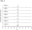
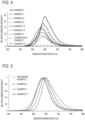
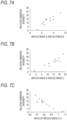
- Fig.3 and Fig. 4 The XRD patterns of the phosphors of examples 3 and 7-12 and the emission spectra of the phosphors of examples 3, 5, and 7-12 and comparative example 1 are shown in Fig.3 and Fig. 4 , respectively.
- Fig. 5 shows emission spectra for the phosphors in examples 3, 7, and 11 and reference example 1 where emission intensity is normalized with the emission peak intensity of each of the phosphors defined as 1.
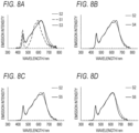
- the reflectance spectra of the phosphors of each of the examples and the comparative example are shown in Figs.
- the phosphor of the embodiments of the present invention is capable of achieving various emission peak wavelengths to match an application by adjusting the composition.
- the phosphors of each example all exhibited extremely high emission intensity as compared to the phosphor of comparative example 1.
- the full width at half maximum of the phosphors of each example was extremely narrow as compared to reference example 1, and by using such a phosphor, a light-emitting device having both favorable conversion efficiency and color rendering or color reproducibility can be provided.
- a SCASN phosphor having an emission peak wavelength of 620 nm (BR-102/D, manufactured by Mitsubishi Chemical Corporation) is used as a first red phosphor
- a phosphor of the examples and the comparative example shown in Table 2 above or a CASN phosphor having an emission peak wavelength of 646 nm (BR-101/J, manufactured by Mitsubishi Chemical Corporation) is used as a second red phosphor
- a LuAG phosphor (BG-801/B4, manufactured by Mitsubishi Chemical Corporation) is used as a green phosphor
- the emission spectra of white LEDs comprising each of the phosphors were calculated on the basis of information for the emission spectrum, the internal quantum efficiency (iQE), and the like of each phosphor.
- Relative value of phosphor mass in Table 3 is a mass ratio of each phosphor when the total mass of each phosphor is treated as 100%.
- Green is the LuAG phosphor described above
- Red 1 is the first red phosphor described above
- Red 2 is the second red phosphor described above.
- the light-emitting devices using the phosphors of each example satisfying the requirements of above embodiments had dramatically improved color reproducibility Ra as compared to a case using the phosphor of comparative example 1, and in addition, LER or R9 or both are improved over a case using the phosphor of reference example 1, and conversion efficiency and color rendering or color reproducibility as well are superior.
- Ra represents an index of color rendering
- a phosphor can be provided having a favorable emission peak wavelength, narrow full width at half maximum, and/or high emission intensity, and by including the phosphor, a light-emitting device, an illumination device, an image display device, and/or an indicator lamp for a vehicle having favorable color rendering, color reproducibility and favorable conversion efficiency can be provided.
- the light-emitting device in the present invention is superior in color rendering, color reproducibility and/or conversion efficiency, the light-emitting device can be suitably used for an illumination device, an image display device, and an indicator lamp for a vehicle.
Landscapes
- Chemical & Material Sciences (AREA)
- Engineering & Computer Science (AREA)
- Inorganic Chemistry (AREA)
- Materials Engineering (AREA)
- Organic Chemistry (AREA)
- General Engineering & Computer Science (AREA)
- Physics & Mathematics (AREA)
- Microelectronics & Electronic Packaging (AREA)
- Optics & Photonics (AREA)
- Spectroscopy & Molecular Physics (AREA)
- Mechanical Engineering (AREA)
- Luminescent Compositions (AREA)
- Vessels And Coating Films For Discharge Lamps (AREA)
Applications Claiming Priority (3)
| Application Number | Priority Date | Filing Date | Title |
|---|---|---|---|
| JP2022007318A JP7253214B1 (ja) | 2022-01-20 | 2022-01-20 | 発光装置、照明装置、画像表示装置及び車両用表示灯 |
| JP2022007320A JP7311867B1 (ja) | 2022-01-20 | 2022-01-20 | 蛍光体 |
| PCT/JP2022/031467 WO2023139824A1 (ja) | 2022-01-20 | 2022-08-19 | 蛍光体、発光装置、照明装置、画像表示装置及び車両用表示灯 |
Publications (3)
| Publication Number | Publication Date |
|---|---|
| EP4293733A1 true EP4293733A1 (de) | 2023-12-20 |
| EP4293733A4 EP4293733A4 (de) | 2024-04-17 |
| EP4293733B1 EP4293733B1 (de) | 2025-10-01 |
Family
ID=86506109
Family Applications (1)
| Application Number | Title | Priority Date | Filing Date |
|---|---|---|---|
| EP22921978.7A Active EP4293733B1 (de) | 2022-01-20 | 2022-08-19 | Phosphor, lichtemittierende vorrichtung, beleuchtungsvorrichtung, bildanzeigevorrichtung und fahrzeuganzeigelampe |
Country Status (5)
| Country | Link |
|---|---|
| US (4) | US11661549B1 (de) |
| EP (1) | EP4293733B1 (de) |
| KR (1) | KR102599819B1 (de) |
| CN (1) | CN116987502B (de) |
| TW (1) | TWI841022B (de) |
Cited By (2)
| Publication number | Priority date | Publication date | Assignee | Title |
|---|---|---|---|---|
| EP4645396A4 (de) * | 2022-12-27 | 2026-04-08 | Mitsubishi Chem Corp | Lichtemittierende vorrichtung, beleuchtungsvorrichtung, bildanzeigevorrichtung und anzeigelampe für fahrzeuge |
| EP4646071A4 (de) * | 2022-12-27 | 2026-04-08 | Mitsubishi Chem Corp | Lichtemittierende vorrichtung, beleuchtungsvorrichtung, bildanzeigevorrichtung und fahrzeuganzeigelampe |
Families Citing this family (2)
| Publication number | Priority date | Publication date | Assignee | Title |
|---|---|---|---|---|
| CN116987502B (zh) * | 2022-01-20 | 2024-12-31 | 三菱化学株式会社 | 荧光体、发光装置、照明装置、图像显示装置和车辆用显示灯 |
| EP4293732B1 (de) * | 2022-01-20 | 2026-04-29 | Mitsubishi Chemical Corporation | Phosphor, lichtemittierende vorrichtung, beleuchtungsvorrichtung, bildanzeigevorrichtung und anzeigelampe für fahrzeuge |
Family Cites Families (63)
| Publication number | Priority date | Publication date | Assignee | Title |
|---|---|---|---|---|
| JPS59167620A (ja) | 1983-03-15 | 1984-09-21 | Sanden Corp | 気化ポツト式燃焼装置 |
| JPS6335884U (de) | 1986-08-22 | 1988-03-08 | ||
| AT410266B (de) | 2000-12-28 | 2003-03-25 | Tridonic Optoelectronics Gmbh | Lichtquelle mit einem lichtemittierenden element |
| US6753096B2 (en) | 2001-11-27 | 2004-06-22 | General Electric Company | Environmentally-stable organic electroluminescent fibers |
| WO2003080764A1 (en) | 2002-03-22 | 2003-10-02 | Nichia Corporation | Nitride phosphor and method for preparation thereof, and light emitting device |
| MY149573A (en) | 2002-10-16 | 2013-09-13 | Nichia Corp | Oxynitride phosphor and production process thereof, and light-emitting device using oxynitride phosphor |
| US7544309B2 (en) | 2002-12-13 | 2009-06-09 | Koninklijke Philips Electronics N.V. | Illumination system comprising a radiation source and a fluorescent material |
| US7052152B2 (en) | 2003-10-03 | 2006-05-30 | Philips Lumileds Lighting Company, Llc | LCD backlight using two-dimensional array LEDs |
| JP3837588B2 (ja) | 2003-11-26 | 2006-10-25 | 独立行政法人物質・材料研究機構 | 蛍光体と蛍光体を用いた発光器具 |
| JP3921545B2 (ja) | 2004-03-12 | 2007-05-30 | 独立行政法人物質・材料研究機構 | 蛍光体とその製造方法 |
| WO2006012234A2 (en) | 2004-06-25 | 2006-02-02 | Sarnoff Corporation | Nitride phosphors and devices |
| KR100841676B1 (ko) | 2004-07-13 | 2008-06-26 | 가부시키가이샤후지쿠라 | 형광체 및 그 형광체를 이용한 전구색광을 발하는 전구색광발광 다이오드 램프 |
| EP1835008B1 (de) | 2004-08-11 | 2019-05-01 | National Institute for Materials Science | Beleuchtungsvorrichtung |
| US7648649B2 (en) | 2005-02-02 | 2010-01-19 | Lumination Llc | Red line emitting phosphors for use in led applications |
| CN102585810A (zh) | 2005-02-28 | 2012-07-18 | 电气化学工业株式会社 | 荧光体及其制造方法及使用了该荧光体的发光元件 |
| EP1935958A4 (de) | 2005-08-10 | 2010-10-27 | Mitsubishi Chem Corp | Leuchtstoff und darauf basierende lichtemittierende vorrichtung |
| WO2007017049A1 (de) | 2005-08-11 | 2007-02-15 | Merck Patent Gmbh | Photonisches material mit regelmässig angeordneten kavitäten |
| KR101264580B1 (ko) | 2005-09-27 | 2013-05-14 | 미쓰비시 가가꾸 가부시키가이샤 | 형광체 및 그 제조방법, 및 상기 형광체를 사용한 발광장치 |
| US20070194321A1 (en) | 2006-02-17 | 2007-08-23 | Semiconductor Energy Laboratory Co., Ltd. | Light emitting element, light emitting device, and electronic device |
| CN101077973B (zh) | 2006-05-26 | 2010-09-29 | 大连路明发光科技股份有限公司 | 硅酸盐荧光材料及其制造方法以及使用其的发光装置 |
| KR101258229B1 (ko) | 2006-06-30 | 2013-04-25 | 서울반도체 주식회사 | 발광 소자 |
| WO2008004640A1 (en) | 2006-07-05 | 2008-01-10 | Ube Industries, Ltd. | Sialon-base oxynitride phosphors and process for production thereof |
| DE102006054331A1 (de) | 2006-11-17 | 2008-05-21 | Merck Patent Gmbh | Leuchtstoffkörper basierend auf plättchenförmigen Substraten |
| JP5367218B2 (ja) | 2006-11-24 | 2013-12-11 | シャープ株式会社 | 蛍光体の製造方法および発光装置の製造方法 |
| US7857994B2 (en) | 2007-05-30 | 2010-12-28 | GE Lighting Solutions, LLC | Green emitting phosphors and blends thereof |
| EP2009078A1 (de) | 2007-06-29 | 2008-12-31 | Leuchtstoffwerk Breitungen GmbH | Ce3+- und Eu2+-aktivierte Alkali-Erdsilizium-Nitridphosphore |
| JP2009019163A (ja) | 2007-07-13 | 2009-01-29 | Sharp Corp | 発光装置用蛍光体粒子集合体、発光装置、および液晶表示用バックライト装置 |
| WO2009011205A1 (ja) | 2007-07-19 | 2009-01-22 | Sharp Kabushiki Kaisha | 発光装置 |
| JP5578597B2 (ja) | 2007-09-03 | 2014-08-27 | 独立行政法人物質・材料研究機構 | 蛍光体及びその製造方法、並びにそれを用いた発光装置 |
| KR100891761B1 (ko) | 2007-10-19 | 2009-04-07 | 삼성전기주식회사 | 반도체 발광소자, 그의 제조방법 및 이를 이용한 반도체발광소자 패키지 |
| DE102007056343A1 (de) | 2007-11-22 | 2009-05-28 | Litec Lll Gmbh | Oberflächemodifizierte Leuchtstoffe |
| US8703016B2 (en) | 2008-10-22 | 2014-04-22 | General Electric Company | Phosphor materials and related devices |
| US9428688B2 (en) | 2008-11-17 | 2016-08-30 | Cree, Inc. | Phosphor composition |
| JP5641384B2 (ja) | 2008-11-28 | 2014-12-17 | 独立行政法人物質・材料研究機構 | 表示装置用照明装置及び表示装置 |
| KR101114061B1 (ko) | 2009-02-23 | 2012-02-21 | 주식회사 포스포 | 형광체 및 발광소자 |
| CN102395650A (zh) | 2009-04-16 | 2012-03-28 | 皇家飞利浦电子股份有限公司 | 发红光的发光材料 |
| JP5185421B2 (ja) | 2010-09-09 | 2013-04-17 | 株式会社東芝 | 赤色発光蛍光体およびそれを用いた発光装置 |
| WO2013175336A1 (en) | 2012-05-22 | 2013-11-28 | Koninklijke Philips N.V. | New phosphors, such as new narrow-band red emitting phosphors, for solid state lighting |
| WO2015044106A1 (en) | 2013-09-26 | 2015-04-02 | Koninklijke Philips N.V. | New nitridoalumosilicate phosphor for solid state lighting |
| US9725648B2 (en) | 2013-12-10 | 2017-08-08 | Samsung Electronics Co., Ltd. | Phosphor and light-emitting device including the same |
| KR102255213B1 (ko) | 2013-12-10 | 2021-05-24 | 삼성전자주식회사 | 형광체와 이를 포함하는 발광 소자 |
| CN106574175B (zh) * | 2014-09-11 | 2018-08-07 | 飞利浦照明控股有限公司 | 具有加强的白色显现和转换效率的pc-led模块 |
| JP6531509B2 (ja) * | 2015-06-16 | 2019-06-19 | 日亜化学工業株式会社 | 窒化物蛍光体、その製造方法及び発光装置 |
| CN105400513A (zh) | 2015-07-21 | 2016-03-16 | 杭州萤鹤光电材料有限公司 | 一种红色荧光粉及其制备方法 |
| JP6291675B2 (ja) | 2015-11-11 | 2018-03-14 | 日亜化学工業株式会社 | 窒化物蛍光体の製造方法、窒化物蛍光体及び発光装置 |
| US10217907B2 (en) | 2016-02-29 | 2019-02-26 | Nichia Corporation | Method of producing nitride fluorescent material, nitride fluorescent material, and light emitting device using the same |
| JP6443417B2 (ja) | 2016-02-29 | 2018-12-26 | 日亜化学工業株式会社 | 窒化物蛍光体の製造方法、窒化物蛍光体及び発光装置 |
| US10784416B2 (en) * | 2016-03-24 | 2020-09-22 | Sharp Kabushiki Kaisha | Light source device and light emitting device |
| JP2017188592A (ja) * | 2016-04-06 | 2017-10-12 | 日亜化学工業株式会社 | 発光装置 |
| CN109699179B (zh) * | 2016-09-26 | 2022-03-29 | 三菱化学株式会社 | 荧光体、发光装置、照明装置以及图像显示装置 |
| JP6763360B2 (ja) * | 2017-09-29 | 2020-09-30 | 日亜化学工業株式会社 | アルミン酸塩蛍光体、発光装置及びアルミン酸塩蛍光体の製造方法 |
| JP6923804B2 (ja) | 2017-12-08 | 2021-08-25 | 日亜化学工業株式会社 | 波長変換部材及びその製造方法 |
| US11060025B2 (en) * | 2017-12-26 | 2021-07-13 | Nichia Corporation | Oxynitride fluorescent material, light emitting device, and method for producing oxynitride fluorescent material |
| TWI671384B (zh) * | 2018-03-27 | 2019-09-11 | 信源陶磁股份有限公司 | 紅色氮化物螢光體及其發光裝置 |
| JPWO2019188377A1 (ja) | 2018-03-28 | 2021-04-15 | デンカ株式会社 | 蛍光体、その製造方法及び発光装置 |
| US10608149B2 (en) * | 2018-03-30 | 2020-03-31 | Nichia Corporation | Wavelength converting member and light emitting device |
| CN115698225B (zh) * | 2020-06-29 | 2025-05-30 | 亮锐有限责任公司 | 磷光体颗粒涂层 |
| JP2023166644A (ja) | 2020-10-13 | 2023-11-22 | デンカ株式会社 | 蛍光体、及び発光装置 |
| JP2023166642A (ja) | 2020-10-13 | 2023-11-22 | デンカ株式会社 | 蛍光体、蛍光体の製造方法、及び発光装置 |
| JP2023166643A (ja) * | 2020-10-13 | 2023-11-22 | デンカ株式会社 | 蛍光体、及び発光装置 |
| CN116802822A (zh) * | 2022-01-20 | 2023-09-22 | 三菱化学株式会社 | 荧光体、发光装置、照明装置、图像显示装置和车辆用显示灯 |
| CN116987502B (zh) | 2022-01-20 | 2024-12-31 | 三菱化学株式会社 | 荧光体、发光装置、照明装置、图像显示装置和车辆用显示灯 |
| EP4293732B1 (de) * | 2022-01-20 | 2026-04-29 | Mitsubishi Chemical Corporation | Phosphor, lichtemittierende vorrichtung, beleuchtungsvorrichtung, bildanzeigevorrichtung und anzeigelampe für fahrzeuge |
-
2022
- 2022-08-19 CN CN202310828411.9A patent/CN116987502B/zh active Active
- 2022-08-19 EP EP22921978.7A patent/EP4293733B1/de active Active
- 2022-08-19 KR KR1020227045598A patent/KR102599819B1/ko active Active
- 2022-09-13 US US17/931,632 patent/US11661549B1/en active Active
- 2022-10-28 TW TW111141188A patent/TWI841022B/zh active
-
2023
- 2023-03-30 US US18/192,690 patent/US11884857B2/en active Active
- 2023-03-30 US US18/192,687 patent/US11884856B2/en active Active
- 2023-12-04 US US18/528,010 patent/US12286575B2/en active Active
Cited By (2)
| Publication number | Priority date | Publication date | Assignee | Title |
|---|---|---|---|---|
| EP4645396A4 (de) * | 2022-12-27 | 2026-04-08 | Mitsubishi Chem Corp | Lichtemittierende vorrichtung, beleuchtungsvorrichtung, bildanzeigevorrichtung und anzeigelampe für fahrzeuge |
| EP4646071A4 (de) * | 2022-12-27 | 2026-04-08 | Mitsubishi Chem Corp | Lichtemittierende vorrichtung, beleuchtungsvorrichtung, bildanzeigevorrichtung und fahrzeuganzeigelampe |
Also Published As
| Publication number | Publication date |
|---|---|
| US20240101898A1 (en) | 2024-03-28 |
| KR102599819B1 (ko) | 2023-11-08 |
| TWI841022B (zh) | 2024-05-01 |
| CN116987502A (zh) | 2023-11-03 |
| US20230242813A1 (en) | 2023-08-03 |
| TW202330871A (zh) | 2023-08-01 |
| EP4293733B1 (de) | 2025-10-01 |
| US11884856B2 (en) | 2024-01-30 |
| CN116987502B (zh) | 2024-12-31 |
| US12286575B2 (en) | 2025-04-29 |
| EP4293733A4 (de) | 2024-04-17 |
| US11884857B2 (en) | 2024-01-30 |
| KR20230113695A (ko) | 2023-08-01 |
| US11661549B1 (en) | 2023-05-30 |
| US20230235221A1 (en) | 2023-07-27 |
Similar Documents
| Publication | Publication Date | Title |
|---|---|---|
| EP4293733A1 (de) | Phosphor, lichtemittierende vorrichtung, beleuchtungsvorrichtung, bildanzeigevorrichtung und fahrzeuganzeigelampe | |
| US12281249B2 (en) | Phosphor, light-emitting device, illumination device, image display device, and indicator lamp for vehicle | |
| JP7311866B1 (ja) | 蛍光体 | |
| CN116802822A (zh) | 荧光体、发光装置、照明装置、图像显示装置和车辆用显示灯 | |
| JP7311867B1 (ja) | 蛍光体 | |
| WO2023139824A1 (ja) | 蛍光体、発光装置、照明装置、画像表示装置及び車両用表示灯 | |
| EP4640790A1 (de) | Phosphor, lichtemittierende vorrichtung, beleuchtungsvorrichtung, bildanzeigevorrichtung und fahrzeuganzeigelampe | |
| JP7253214B1 (ja) | 発光装置、照明装置、画像表示装置及び車両用表示灯 | |
| JP7369409B1 (ja) | 蛍光体、発光装置、照明装置、画像表示装置及び車両用表示灯 | |
| EP4645396A1 (de) | Lichtemittierende vorrichtung, beleuchtungsvorrichtung, bildanzeigevorrichtung und anzeigelampe für fahrzeuge | |
| CN117043971A (zh) | 荧光体、发光装置、照明装置、图像显示装置和车辆用显示灯 | |
| CN116987501A (zh) | 荧光体、发光装置、照明装置、图像显示装置和车辆用显示灯 | |
| WO2023139823A1 (ja) | 蛍光体、発光装置、照明装置、画像表示装置及び車両用表示灯 | |
| CN118043979A (zh) | 荧光体、发光装置、照明装置、图像显示装置和车辆用显示灯 | |
| JP2023057391A (ja) | 蛍光体 |
Legal Events
| Date | Code | Title | Description |
|---|---|---|---|
| STAA | Information on the status of an ep patent application or granted ep patent |
Free format text: STATUS: THE INTERNATIONAL PUBLICATION HAS BEEN MADE |
|
| PUAI | Public reference made under article 153(3) epc to a published international application that has entered the european phase |
Free format text: ORIGINAL CODE: 0009012 |
|
| STAA | Information on the status of an ep patent application or granted ep patent |
Free format text: STATUS: REQUEST FOR EXAMINATION WAS MADE |
|
| 17P | Request for examination filed |
Effective date: 20230914 |
|
| AK | Designated contracting states |
Kind code of ref document: A1 Designated state(s): AL AT BE BG CH CY CZ DE DK EE ES FI FR GB GR HR HU IE IS IT LI LT LU LV MC MK MT NL NO PL PT RO RS SE SI SK SM TR |
|
| A4 | Supplementary search report drawn up and despatched |
Effective date: 20240315 |
|
| RIC1 | Information provided on ipc code assigned before grant |
Ipc: H01L 33/32 20100101ALI20240312BHEP Ipc: H05B 33/14 20060101ALI20240312BHEP Ipc: F21Y 115/10 20160101ALI20240312BHEP Ipc: F21W 103/35 20180101ALI20240312BHEP Ipc: F21V 9/38 20180101ALI20240312BHEP Ipc: F21S 43/14 20180101ALI20240312BHEP Ipc: C09K 11/77 20060101ALI20240312BHEP Ipc: H01L 33/50 20100101AFI20240312BHEP |
|
| STAA | Information on the status of an ep patent application or granted ep patent |
Free format text: STATUS: EXAMINATION IS IN PROGRESS |
|
| 17Q | First examination report despatched |
Effective date: 20250109 |
|
| DAV | Request for validation of the european patent (deleted) | ||
| DAX | Request for extension of the european patent (deleted) | ||
| REG | Reference to a national code |
Ref legal event code: R079 Ipc: C09K0011770000 Ref country code: DE Ref legal event code: R079 Ref document number: 602022022529 Country of ref document: DE Free format text: PREVIOUS MAIN CLASS: H01L0033500000 Ipc: C09K0011770000 |
|
| GRAP | Despatch of communication of intention to grant a patent |
Free format text: ORIGINAL CODE: EPIDOSNIGR1 |
|
| STAA | Information on the status of an ep patent application or granted ep patent |
Free format text: STATUS: GRANT OF PATENT IS INTENDED |
|
| RIC1 | Information provided on ipc code assigned before grant |
Ipc: F21W 103/35 20180101ALI20250429BHEP Ipc: H10H 20/851 20250101ALI20250429BHEP Ipc: H05B 33/14 20060101ALI20250429BHEP Ipc: F21Y 115/10 20160101ALI20250429BHEP Ipc: F21V 9/38 20180101ALI20250429BHEP Ipc: F21S 43/14 20180101ALI20250429BHEP Ipc: C09K 11/77 20060101AFI20250429BHEP |
|
| INTG | Intention to grant announced |
Effective date: 20250515 |
|
| GRAS | Grant fee paid |
Free format text: ORIGINAL CODE: EPIDOSNIGR3 |
|
| GRAA | (expected) grant |
Free format text: ORIGINAL CODE: 0009210 |
|
| STAA | Information on the status of an ep patent application or granted ep patent |
Free format text: STATUS: THE PATENT HAS BEEN GRANTED |
|
| AK | Designated contracting states |
Kind code of ref document: B1 Designated state(s): AL AT BE BG CH CY CZ DE DK EE ES FI FR GB GR HR HU IE IS IT LI LT LU LV MC MK MT NL NO PL PT RO RS SE SI SK SM TR |
|
| REG | Reference to a national code |
Ref country code: GB Ref legal event code: FG4D Ref country code: CH Ref legal event code: F10 Free format text: ST27 STATUS EVENT CODE: U-0-0-F10-F00 (AS PROVIDED BY THE NATIONAL OFFICE) Effective date: 20251001 |
|
| REG | Reference to a national code |
Ref country code: DE Ref legal event code: R096 Ref document number: 602022022529 Country of ref document: DE |
|
| REG | Reference to a national code |
Ref country code: IE Ref legal event code: FG4D |
|
| REG | Reference to a national code |
Ref country code: NL Ref legal event code: MP Effective date: 20251001 |
|
| REG | Reference to a national code |
Ref country code: AT Ref legal event code: MK05 Ref document number: 1842531 Country of ref document: AT Kind code of ref document: T Effective date: 20251001 |
|
| PG25 | Lapsed in a contracting state [announced via postgrant information from national office to epo] |
Ref country code: NL Free format text: LAPSE BECAUSE OF FAILURE TO SUBMIT A TRANSLATION OF THE DESCRIPTION OR TO PAY THE FEE WITHIN THE PRESCRIBED TIME-LIMIT Effective date: 20251001 |
|
| PG25 | Lapsed in a contracting state [announced via postgrant information from national office to epo] |
Ref country code: ES Free format text: LAPSE BECAUSE OF FAILURE TO SUBMIT A TRANSLATION OF THE DESCRIPTION OR TO PAY THE FEE WITHIN THE PRESCRIBED TIME-LIMIT Effective date: 20251001 |
|
| REG | Reference to a national code |
Ref country code: LT Ref legal event code: MG9D |
|
| PG25 | Lapsed in a contracting state [announced via postgrant information from national office to epo] |
Ref country code: NO Free format text: LAPSE BECAUSE OF FAILURE TO SUBMIT A TRANSLATION OF THE DESCRIPTION OR TO PAY THE FEE WITHIN THE PRESCRIBED TIME-LIMIT Effective date: 20260101 |
|
| PG25 | Lapsed in a contracting state [announced via postgrant information from national office to epo] |
Ref country code: AT Free format text: LAPSE BECAUSE OF FAILURE TO SUBMIT A TRANSLATION OF THE DESCRIPTION OR TO PAY THE FEE WITHIN THE PRESCRIBED TIME-LIMIT Effective date: 20251001 Ref country code: HR Free format text: LAPSE BECAUSE OF FAILURE TO SUBMIT A TRANSLATION OF THE DESCRIPTION OR TO PAY THE FEE WITHIN THE PRESCRIBED TIME-LIMIT Effective date: 20251001 Ref country code: FI Free format text: LAPSE BECAUSE OF FAILURE TO SUBMIT A TRANSLATION OF THE DESCRIPTION OR TO PAY THE FEE WITHIN THE PRESCRIBED TIME-LIMIT Effective date: 20251001 |
|
| PG25 | Lapsed in a contracting state [announced via postgrant information from national office to epo] |
Ref country code: RS Free format text: LAPSE BECAUSE OF FAILURE TO SUBMIT A TRANSLATION OF THE DESCRIPTION OR TO PAY THE FEE WITHIN THE PRESCRIBED TIME-LIMIT Effective date: 20260101 |
|
| PG25 | Lapsed in a contracting state [announced via postgrant information from national office to epo] |
Ref country code: IS Free format text: LAPSE BECAUSE OF FAILURE TO SUBMIT A TRANSLATION OF THE DESCRIPTION OR TO PAY THE FEE WITHIN THE PRESCRIBED TIME-LIMIT Effective date: 20260201 |
|
| PG25 | Lapsed in a contracting state [announced via postgrant information from national office to epo] |
Ref country code: PT Free format text: LAPSE BECAUSE OF FAILURE TO SUBMIT A TRANSLATION OF THE DESCRIPTION OR TO PAY THE FEE WITHIN THE PRESCRIBED TIME-LIMIT Effective date: 20260202 Ref country code: CZ Free format text: LAPSE BECAUSE OF FAILURE TO SUBMIT A TRANSLATION OF THE DESCRIPTION OR TO PAY THE FEE WITHIN THE PRESCRIBED TIME-LIMIT Effective date: 20251001 |
|
| PG25 | Lapsed in a contracting state [announced via postgrant information from national office to epo] |
Ref country code: PL Free format text: LAPSE BECAUSE OF FAILURE TO SUBMIT A TRANSLATION OF THE DESCRIPTION OR TO PAY THE FEE WITHIN THE PRESCRIBED TIME-LIMIT Effective date: 20251001 |
|
| PG25 | Lapsed in a contracting state [announced via postgrant information from national office to epo] |
Ref country code: LV Free format text: LAPSE BECAUSE OF FAILURE TO SUBMIT A TRANSLATION OF THE DESCRIPTION OR TO PAY THE FEE WITHIN THE PRESCRIBED TIME-LIMIT Effective date: 20251001 |