EP4295663A1 - Dispositif de ramassage de balles pour recevoir des balles rondes d'une presse à balles rondes - Google Patents
Dispositif de ramassage de balles pour recevoir des balles rondes d'une presse à balles rondes Download PDFInfo
- Publication number
- EP4295663A1 EP4295663A1 EP23181072.2A EP23181072A EP4295663A1 EP 4295663 A1 EP4295663 A1 EP 4295663A1 EP 23181072 A EP23181072 A EP 23181072A EP 4295663 A1 EP4295663 A1 EP 4295663A1
- Authority
- EP
- European Patent Office
- Prior art keywords
- receiving device
- bale
- coupling
- drawbar
- bale receiving
- Prior art date
- Legal status (The legal status is an assumption and is not a legal conclusion. Google has not performed a legal analysis and makes no representation as to the accuracy of the status listed.)
- Pending
Links
- 230000008878 coupling Effects 0.000 claims abstract description 92
- 238000010168 coupling process Methods 0.000 claims abstract description 92
- 238000005859 coupling reaction Methods 0.000 claims abstract description 92
- 230000005540 biological transmission Effects 0.000 description 1
- 230000005484 gravity Effects 0.000 description 1
- 239000000463 material Substances 0.000 description 1
- 230000000284 resting effect Effects 0.000 description 1
- 239000007787 solid Substances 0.000 description 1
Images

Classifications
-
- A—HUMAN NECESSITIES
- A01—AGRICULTURE; FORESTRY; ANIMAL HUSBANDRY; HUNTING; TRAPPING; FISHING
- A01B—SOIL WORKING IN AGRICULTURE OR FORESTRY; PARTS, DETAILS, OR ACCESSORIES OF AGRICULTURAL MACHINES OR IMPLEMENTS, IN GENERAL
- A01B59/00—Devices specially adapted for connection between animals or tractors and agricultural machines or implements
- A01B59/04—Devices specially adapted for connection between animals or tractors and agricultural machines or implements for machines pulled or pushed by a tractor
-
- A—HUMAN NECESSITIES
- A01—AGRICULTURE; FORESTRY; ANIMAL HUSBANDRY; HUNTING; TRAPPING; FISHING
- A01F—PROCESSING OF HARVESTED PRODUCE; HAY OR STRAW PRESSES; DEVICES FOR STORING AGRICULTURAL OR HORTICULTURAL PRODUCE
- A01F15/00—Baling presses for straw, hay or the like
- A01F15/08—Details
- A01F15/0875—Discharge devices
- A01F15/0883—Discharge devices for round balers
-
- A—HUMAN NECESSITIES
- A01—AGRICULTURE; FORESTRY; ANIMAL HUSBANDRY; HUNTING; TRAPPING; FISHING
- A01D—HARVESTING; MOWING
- A01D87/00—Loaders for hay or like field crops
- A01D87/12—Loaders for sheaves, stacks or bales
- A01D87/125—Loaders for sheaves, stacks or bales mounted on the press without laying down the bales
-
- A—HUMAN NECESSITIES
- A01—AGRICULTURE; FORESTRY; ANIMAL HUSBANDRY; HUNTING; TRAPPING; FISHING
- A01D—HARVESTING; MOWING
- A01D90/00—Vehicles for carrying harvested crops with means for selfloading or unloading
- A01D90/02—Loading means
- A01D90/08—Loading means with bale-forming means additionally used for loading; with means for picking-up bales and transporting them into the vehicle
- A01D90/083—Round-bale trailers
-
- A—HUMAN NECESSITIES
- A01—AGRICULTURE; FORESTRY; ANIMAL HUSBANDRY; HUNTING; TRAPPING; FISHING
- A01F—PROCESSING OF HARVESTED PRODUCE; HAY OR STRAW PRESSES; DEVICES FOR STORING AGRICULTURAL OR HORTICULTURAL PRODUCE
- A01F15/00—Baling presses for straw, hay or the like
- A01F15/07—Rotobalers, i.e. machines for forming cylindrical bales by winding and pressing
-
- B—PERFORMING OPERATIONS; TRANSPORTING
- B60—VEHICLES IN GENERAL
- B60D—VEHICLE CONNECTIONS
- B60D1/00—Traction couplings; Hitches; Draw-gear; Towing devices
- B60D1/14—Draw-gear or towing devices characterised by their type
- B60D1/145—Draw-gear or towing devices characterised by their type consisting of an elongated single bar or tube
-
- B—PERFORMING OPERATIONS; TRANSPORTING
- B60—VEHICLES IN GENERAL
- B60D—VEHICLE CONNECTIONS
- B60D1/00—Traction couplings; Hitches; Draw-gear; Towing devices
- B60D2001/001—Traction couplings; Hitches; Draw-gear; Towing devices specially adapted for use on vehicles other than cars
- B60D2001/008—Traction couplings; Hitches; Draw-gear; Towing devices specially adapted for use on vehicles other than cars specially adapted for implements, e.g. towed tools
-
- B—PERFORMING OPERATIONS; TRANSPORTING
- B60—VEHICLES IN GENERAL
- B60P—VEHICLES ADAPTED FOR LOAD TRANSPORTATION OR TO TRANSPORT, TO CARRY, OR TO COMPRISE SPECIAL LOADS OR OBJECTS
- B60P3/00—Vehicles adapted to transport, to carry or to comprise special loads or objects
- B60P3/035—Vehicles adapted to transport, to carry or to comprise special loads or objects for transporting reel units
Definitions
- the invention relates to a bale receiving device for receiving at least one round bale from a round baler.
- the invention further relates to a vehicle combination comprising the bale pick-up device.
- the bale receiving device comprises a coupling device with at least one coupling frame element, which is designed for stationary arrangement on a machine frame of the round baler.
- the bale receiving device comprises at least one drawbar element which extends at least partially in a receiving direction between the coupling frame element and a machine frame of the bale device.
- the drawbar element is mounted on the coupling device in such a way that it can be pivoted relative to the coupling frame element at least about a vertical axis, which is arranged at right angles to a contact surface of the bale receiving device at least in a first position of the coupling device.
- bale receiving device has become known as a bale wrapper, which is to be attached to the round baler and is designed to wrap the round bale with a wrapping material.
- the known bale receiving device is disadvantageous, on the one hand, because the coupling device and the drawbar element are only one allow slight pivoting of the round baler relative to the bale receiving device, which limits the curve radius that can be achieved during operation and regularly leads to collisions between the coupling device and the bale receiving device.
- the bale receiving device is disadvantageous, since the coupling device and the drawbar element itself are designed to taper towards the vertical axis in such a way to enable the slight pivoting that there is a gap on the side of the vertical axis between the coupling device and the drawbar element, into which the round bale falls while being picked up from the Round baler can fall sideways before it has reached the machine frame of the bale pick-up device.
- the object of the present invention is to provide a generic bale pick-up device and a vehicle combination comprising the bale pick-up device, which avoid the disadvantages described above.
- the bale receiving device has a transfer element.
- the transfer element is mounted on the coupling device and can be pivoted relative to the drawbar element at least about the vertical axis.
- the transfer element extends in the receiving direction in such a way that the drawbar element is at least partially arranged between the transfer element and the contact surface in a side view or a longitudinal section.
- the bale pick-up device is in particular a vehicle that is to be coupled to the round baler and includes its own chassis.
- the Bale receiving device preferably forms a receiving section for the round bale that adjoins the round baler, in particular a press chamber thereof. Due to the standardized round bale dimensions, the receiving section preferably has a width of at least 1.20 m and a height of at least 1.20 m.
- the bale receiving device is preferably designed to hold and transport several, in particular at least four, round bales.
- the bale receiving device is preferably designed in such a way that the round bales are not displaced laterally from their position in the baling chamber when they are picked up (in-line recording).
- the coupling frame element is in particular to be fixed immovably to the machine frame of the round baler, preferably screwed.
- the bale receiving device preferably has two coupling frame elements that are offset from one another transversely to the receiving direction.
- the at least one coupling frame element is, in particular, lower link catch hooks, which have proven themselves in agriculture for attaching work machines.
- the imaginary vertical axis is preferably arranged centrally in a front view of the bale receiving device, that is to say within a longitudinal center plane.
- the longitudinal center plane is spanned by the vertical axis and a longitudinal axis running in a direction of travel in which the bale receiving device is to be moved across the field during operation.
- the coupling device is in particular designed to be mirror-symmetrical to the longitudinal center plane.
- the recording direction is preferably perpendicular to the vertical axis and/or at least partially aligned against the direction of travel.
- the contact area is an imaginary, flat surface that adjoins the chassis, preferably wheels, of the bale pick-up device without cutting it, and extends in the direction of travel and / or corresponds to the ground surface of the field, provided it is flat.
- the vertical axis runs vertically when the contact area extends horizontally and the coupling device is arranged in the first position.
- the vertical axis runs at an angle of ⁇ 90° to the contact surface.
- the drawbar element connects the coupling device to the machine frame of the bale receiving device.
- the machine frame is preferably designed to be rigid with respect to a chassis axis of the bale receiving device and/or preferably has at least two side longitudinal beams.
- the drawbar element is preferably not pivotable relative to the machine frame about a pivot axis that is angled to the contact surface.
- the drawbar element preferably comprises a central support which extends against the receiving direction from the machine frame to the coupling device and is subject to tension.
- the drawbar element can be pivoted relative to the coupling frame element by approximately 140° about the vertical axis.
- the transfer element is arranged such that at least part of it is arranged above at least part of the drawbar element during operation.
- the Transfer element extends from the coupling device preferably in the receiving direction beyond the vertical axis.
- the transfer element is in particular mounted in such a way that it is not pivotally movable relative to the coupling frame element about an axis that is angled to the contact surface, such as the vertical axis.
- the transfer element therefore does not follow a pivoting of the machine frame of the bale receiving device relative to the round baler during operation.
- the transfer element preferably extends mainly elongated and relatively flat in the receiving direction and/or parallel to the main extension direction of the drawbar element.
- the transfer element solves the problem in that, on the one hand, the coupling device and/or the drawbar element can be made so narrow or tapered to the vertical axis that the drawbar element can be pivoted sufficiently far relative to the coupling device in agricultural operations. On the other hand, the round bale is prevented from falling into the gap by the transfer element bridging it.
- the transfer element is designed in particular in such a way that a collision with it during pivoting is excluded.
- the transfer element is mounted on the coupling device in such a way that it is pivotally movable relative to the coupling frame element about a transverse axis parallel to the contact surface.
- the imaginary transverse axis is positioned in particular in a stationary manner relative to the coupling frame element. Due to the pivoting bearing in this way of the transfer element, in the event of a change in the incline and/or slope of the field on which the bale pick-up device is operated, it can adjust its position in favor of reliable pick-up of the round bale.
- the vertical axis and the transverse axis are preferably arranged in such a way that they do not intersect, that is, that they are spaced apart from one another.
- the vertical axis is arranged offset in relation to the transverse axis, particularly in the recording direction.
- the drawbar element is mounted on the coupling device in such a way that it is pivotally movable relative to the coupling frame element about an axis parallel to the contact surface.
- the drawbar element is mounted in such a way that it is pivotally movable about the transverse axis relative to the coupling frame element, just like the transfer element.
- the transfer element is mounted on the coupling device in such a way that it can be pivoted about the transverse axis relative to the drawbar element.
- the transfer element and the drawbar element are not only pivotable relative to the coupling frame element, but also relative to each other about the transverse axis. This reduces the risk of the pivoting movement of the drawbar element being blocked reduced relative to the transfer element around the vertical axis and the transfer element can move upwards.
- the transfer element and the drawbar element are not mounted so that they can pivot relative to one another about the transverse axis, which means that the probability of failure can be reduced by saving a joint elsewhere.
- the coupling device preferably has an intermediate coupling element that is mounted on the coupling frame element so that it can pivot only about the transverse axis and that is mounted on the drawbar element so that it can only pivot about the vertical axis. Thanks to the intermediate coupling element, the above-described pivoting movements can be implemented using two separate joints, each of which only allows one pivoting direction, the probability of failure of which is lower than that of a complex joint. In addition, with the intermediate coupling element, part of the coupling device can contribute to receiving the round bale. To further simplify the design, the transfer element is preferably mounted on the intermediate coupling element away from the coupling frame element.
- the transfer element preferably has a radial extent related to the transverse axis, which, at least in a straight-ahead position of the bale receiving device, corresponds to at least half, preferably two thirds, particularly preferably three quarters or more, of the distance of the machine frame of the bale receiving device from the transverse axis.
- the transfer element is preferably designed such that its radial extent is variable.
- at least one The end of the transfer element facing the machine frame of the bale receiving device is formed by an adjustable extension element.
- the bale pick-up device is positioned in the straight-ahead position during operation when the bale pick-up device is moved straight ahead, that is, without cornering, in the field. Due to the radial extent of the transfer element, it reaches close to the machine frame of the bale receiving device and in particular has a length that is at least similar to the length of the drawbar element. This minimizes the risk of the round bale falling between the machine frame and the transfer element.
- the distance of the vertical axis from the machine frame of the bale receiving device is at least as large as the distance of the vertical axis from the transverse axis.
- the distance between the vertical axis and the machine frame is at least twice as large or even at least five times as large as the distance between the vertical axis and the transverse axis.
- the vertical axis can be arranged particularly far forward, in particular below the press chamber of the round baler, which results in several advantages. On the one hand, this reduces the pivoting angle of the drawbar element relative to the coupling device around the vertical axis when cornering in a comparable manner and results in more stable driving dynamics achieved by the bale pick-up device.
- this arrangement of the vertical axis allows the round bale to be picked up even at least when cornering or pivoting angles around the vertical axis.
- the bale receiving device preferably has at least one drawbar adjusting element.
- the drawbar adjusting element is designed to pivot the drawbar element relative to the machine frame of the bale receiving device about a drawbar pivot axis, which is arranged parallel to the transverse axis in the straight-ahead position of the bale receiving device.
- the drawbar actuating element is in particular a hydraulic cylinder.
- the bale receiving device preferably has two drawbar adjusting elements which are arranged on two opposite sides of the machine frame.
- the drawbar control element allows the drawbar element and the machine frame to be lowered into a V-shape at least to a large extent and in particular down to the contact area, whereupon the receiving direction is directed downwards. When lowered, the round bale reaches the machine frame of the bale pick-up device more easily because of gravity.
- the drawbar element is rigidly arranged on the machine frame.
- the transfer element preferably has a support section for supporting the transfer element on the drawbar element.
- the transfer element rests with the support section on the drawbar element during operation.
- the support section in particular has a surface directed towards the contact area on.
- the transfer element is therefore preferably mounted in the front area on the coupling device, in particular on the intermediate coupling element, and in the rear area on the drawbar element. This storage is advantageous regardless of whether the transfer element can be pivoted about the transverse axis relative to the drawbar element.
- the support section is advantageous in that the weight of a round bale resting above the drawbar element on the transfer element does not have to be derived solely via the coupling device and the transfer element has to be made correspondingly solid, but rather directly on the drawbar element and in particular consequently at least partially on the chassis of the bale receiving device is to be derived.
- the support section and/or its described surface particularly preferably extends at least essentially or exactly in a circular arc shape around the vertical axis.
- the support section is formed by a tube with a cross section that is symmetrical to a center line, the center line extending in a circular arc around the vertical axis.
- the support section preferably extends by at least 90°, in particular at least by the maximum pivot angle of the drawbar element relative to the coupling frame element around the vertical axis.
- a ball bearing or a plain bearing in particular made of plastic, is arranged between the drawbar element and the transfer element.
- the plain bearing is in particular as a between the drawbar element and a friction-reducing plastic element, for example a plastic plate, arranged on the transfer element, preferably on the drawbar element.
- the ball bearing or an alternative roller or barrel bearing is particularly advantageous if the transfer element is not pivotable about the transverse axis relative to the drawbar element.
- the ball bearing or the plain bearing achieves the advantageous power transmission without causing wear and tear that endangers the reliability of the two receiving devices.
- the transfer element preferably has at least two transfer sections which extend elongated in the receiving direction, between which the drawbar element extends at least partially in a plan view at least in the straight-ahead position.
- the drawbar element extends in particular elongated in the longitudinal center plane.
- the transfer sections extend offset from the longitudinal center plane and elongated parallel to it and are in particular designed to be mirror-symmetrical to the longitudinal center plane.
- the transfer sections allow the round bale to roll smoothly in the pickup direction.
- the transfer element is in particular designed in one piece and/or rigidly.
- the transfer sections are preferably welded to the support section and in particular to a cross member of the transfer element which extends parallel to the transverse axis.
- the object is further achieved by a vehicle combination comprising the round baler described above and/or below and the bale receiving device described above and/or below, which is coupled to the round baler.
- the at least one coupling frame element is arranged in a stationary manner on a machine frame of the round baler.
- the round baler is preferably a self-propelled round baler or one that is attached to a tractor during operation.
- the coupling frame element is to be considered as being enclosed by the machine frame of the round baler.
- the transfer element and the drawbar element do not have to be supported on the same component of the machine frame of the round baler.
- the at least one coupling frame element is arranged on a chassis axle encompassed by the machine frame of the round baler.
- the chassis axle is a rigid component on which wheels are mounted laterally and which extends horizontally below the press chamber.
- the vertical axis can in practice be arranged particularly far forward in order to achieve the advantages described above.
- the transverse axis is arranged in particular behind the chassis axle, that is to say offset in the receiving direction from the chassis axle. This makes it possible to reliably guide the round bale to the machine frame of the bale pick-up device.
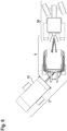
- the Fig. 1, 2 and 6 show a vehicle combination 26 according to the invention comprising a round baler 4 pulled by a tractor 30 and a bale pick-up device 2 coupled to the round baler 4.
- the bale pick-up device 2 is used to pick up several round bales, not shown, from the round baler 4 in order to be able to deposit the round bales in a collected manner and not afterwards having to pick up each round bale individually.
- the bale receiving device 2 comprises a coupling device 6.
- the coupling device 6 comprises two coupling frame elements 8, which are arranged in a stationary manner on a vehicle axle 32 of a machine frame 10 of the round baler 4 (cf. Fig. 3 and 4 ).
- the coupling device 6 comprises an intermediate coupling element 18.
- the intermediate coupling element 18 is mounted on the coupling frame elements 8 so that it can pivot about a transverse axis HA.
- a drawbar element 14 is mounted on the intermediate coupling element 18 so that it can pivot about a vertical axis VA.
- a longitudinal axis LA is in particular arranged at right angles to both the vertical axis VA and the transverse axis HA, at least in one position.
- the drawbar element 14 extends in a receiving direction AR between the intermediate coupling element 18 and a machine frame 12 of the receiving device 2.
- the vertical axis VA extends at least in a first position of the coupling device 6 at right angles to a contact area AF of the bale receiving device 2 (cf. Fig. 1 ).
- a transfer element 16 is mounted on the intermediate coupling element 18 so that it can pivot about the transverse axis HA.
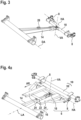
- the transfer element 16 is immovable relative to the coupling device 6 about the vertical axis VA or an axis parallel thereto (cf. Fig. 4 and 7 ).
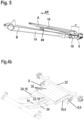
- the transfer element 16 extends in the receiving direction AR in such a way that the drawbar element 14 in the longitudinal section or the side view Fig. 5 is at least partially arranged between the transfer element 16 and the contact surface AF.
- the transfer element 16 has a radial extension A related to the transverse axis HA, which corresponds to at least two thirds of a distance B of the machine frame 12 of the bale receiving device 2 from the transverse axis HA (cf. Fig. 5 ).
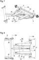
- the radial extent of the bale receiving device 2 is as follows Fig. 8 variable by screwed extension elements 34 of the transfer element 16.
- a distance C of the vertical axis VA from the machine frame 12 of the bale receiving device 2 (cf. Fig. 8 ) at least five times as large as a distance D of the vertical axis VA from the transverse axis (cf. Fig. 5 ).
- the bale receiving device 2 has two drawbar adjusting elements 20, which are designed to pivot the drawbar element 14 relative to the machine frame 12 of the bale receiving device 2 about a drawbar pivot axis DA, which is in the with Fig. 1 and 2
- the straight-ahead position of the bale receiving device 2 shown runs parallel to the transverse axis HA (cf. Fig. 8 ).
- the transfer element 16 has a support section 22 which extends in a circle around the vertical axis VA and which is in the Fig. 4a , 7 and 8 is shown in simplified form consisting of straight elements that are angled towards one another.
- the support section 22 serves to support the transfer element 16 on the drawbar element 14.
- a sliding bearing 28 made of plastic is arranged on the drawbar element 14, which allows the drawbar element 14 to be pivoted relative to the transfer element 16 about the vertical axis VA (cf. Fig. 7 ).
- the transfer element 16 has two transfer sections 24 which extend elongately in the receiving direction AR, between which in the top view according to Fig. 8 the drawbar element 14 is arranged.
- the support section 22 is approximately U-shaped and also carries rollers 35.
Landscapes
- Life Sciences & Earth Sciences (AREA)
- Environmental Sciences (AREA)
- Engineering & Computer Science (AREA)
- Mechanical Engineering (AREA)
- Zoology (AREA)
- Soil Sciences (AREA)
- Transportation (AREA)
- Storage Of Harvested Produce (AREA)
- Agricultural Machines (AREA)
Applications Claiming Priority (1)
| Application Number | Priority Date | Filing Date | Title |
|---|---|---|---|
| DE102022115781.4A DE102022115781A1 (de) | 2022-06-24 | 2022-06-24 | Ballenaufnahmevorrichtung zur Aufnahme von Rundballen einer Rundballenpresse |
Publications (1)
| Publication Number | Publication Date |
|---|---|
| EP4295663A1 true EP4295663A1 (fr) | 2023-12-27 |
Family
ID=86942821
Family Applications (1)
| Application Number | Title | Priority Date | Filing Date |
|---|---|---|---|
| EP23181072.2A Pending EP4295663A1 (fr) | 2022-06-24 | 2023-06-22 | Dispositif de ramassage de balles pour recevoir des balles rondes d'une presse à balles rondes |
Country Status (3)
| Country | Link |
|---|---|
| US (1) | US20230413707A1 (fr) |
| EP (1) | EP4295663A1 (fr) |
| DE (1) | DE102022115781A1 (fr) |
Citations (5)
| Publication number | Priority date | Publication date | Assignee | Title |
|---|---|---|---|---|
| US3480163A (en) * | 1968-02-23 | 1969-11-25 | Int Harvester Co | Steering arm for bale thrower |
| DE3304166C2 (de) * | 1983-02-08 | 1986-05-15 | Busatis-Werke GmbH u. Co KG, 5630 Remscheid | Rundballenübernahme- und Transportfahrzeug |
| EP0404668A1 (fr) * | 1989-06-19 | 1990-12-27 | Jean-François Bregeron | Machine agricole pour le regroupement de balles |
| CA2165111A1 (fr) * | 1995-12-13 | 1997-06-14 | Richard Kohnen | Semi-remorque pour le stockage de recoltes en vue de leur mise en balle |
| US20050188862A1 (en) * | 2004-02-28 | 2005-09-01 | Hoover Larry L. | Torsion spring activated round bale kicker |
Family Cites Families (3)
| Publication number | Priority date | Publication date | Assignee | Title |
|---|---|---|---|---|
| US4815266A (en) * | 1987-09-30 | 1989-03-28 | Hesston Corporation | Continuous round baler with accumulating trailer |
| US6607342B1 (en) * | 2001-12-28 | 2003-08-19 | Michael W. Tolzin | Bale transporting apparatus |
| DE102019201337A1 (de) * | 2019-02-01 | 2020-08-06 | Deere & Company | Landwirtschaftliches Arbeitsgerät, Deichselvorrichtung und Zugfahrzeug-Arbeitsgerät-Kombination |
-
2022
- 2022-06-24 DE DE102022115781.4A patent/DE102022115781A1/de active Pending
-
2023
- 2023-06-22 EP EP23181072.2A patent/EP4295663A1/fr active Pending
- 2023-06-23 US US18/340,634 patent/US20230413707A1/en active Pending
Patent Citations (5)
| Publication number | Priority date | Publication date | Assignee | Title |
|---|---|---|---|---|
| US3480163A (en) * | 1968-02-23 | 1969-11-25 | Int Harvester Co | Steering arm for bale thrower |
| DE3304166C2 (de) * | 1983-02-08 | 1986-05-15 | Busatis-Werke GmbH u. Co KG, 5630 Remscheid | Rundballenübernahme- und Transportfahrzeug |
| EP0404668A1 (fr) * | 1989-06-19 | 1990-12-27 | Jean-François Bregeron | Machine agricole pour le regroupement de balles |
| CA2165111A1 (fr) * | 1995-12-13 | 1997-06-14 | Richard Kohnen | Semi-remorque pour le stockage de recoltes en vue de leur mise en balle |
| US20050188862A1 (en) * | 2004-02-28 | 2005-09-01 | Hoover Larry L. | Torsion spring activated round bale kicker |
Also Published As
| Publication number | Publication date |
|---|---|
| US20230413707A1 (en) | 2023-12-28 |
| DE102022115781A1 (de) | 2024-01-04 |
Similar Documents
| Publication | Publication Date | Title |
|---|---|---|
| EP0543145B1 (fr) | Dispositif pour emballer des balles rondes | |
| EP1210862B1 (fr) | Presse et appareil pour envelopper des balles rondes | |
| DE2623209A1 (de) | Erbsen-erntemaschine | |
| DE2530249A1 (de) | Wickelballenpresse | |
| EP0934690A1 (fr) | Dispositif d'andainage | |
| DE2851117A1 (de) | Sammel- und ablegevorrichtung fuer pressballen | |
| EP1726204B1 (fr) | Presse et appareil pour envelopper des balles rondes | |
| EP3788864B1 (fr) | Dispositif de montage pour machine de travail agricole, machine de travail agricole et attelage pourvue d'une telle machine de travail agricole | |
| EP4295663A1 (fr) | Dispositif de ramassage de balles pour recevoir des balles rondes d'une presse à balles rondes | |
| EP4245121B1 (fr) | Dispositif pour basculer le déchargement de balles rondes | |
| DE10334680B4 (de) | Vorrichtung zum Umhüllen oder Verpacken von insbesondere landwirtschaftlichen Erntegutballen | |
| EP4466977B1 (fr) | Presse à balles pour récolte agricole | |
| EP1588601B1 (fr) | Machine de récolte avec un dispositif de décharge | |
| EP4176705A1 (fr) | Presse à balles rondes avec un dispositif pour serrer une balle | |
| EP4491009B1 (fr) | Dispositif de basculement de déchargement et presse à balles ou enrouleur | |
| EP0959661B1 (fr) | Procede pour produire des balles de paille et dispositif permettant de mettre ledit procede en oeuvre | |
| EP1738634A1 (fr) | Dispositif de ramassage de produits de récolte ainsi que machine de récolte. | |
| DE102022105847A1 (de) | Schwadaufnehmer mit drittem Stützrad | |
| AT520228A1 (de) | Ballentransportwagen | |
| EP4417037B1 (fr) | Dispositif de coupe pour récolte agricole en forme de tige | |
| WO2016118986A1 (fr) | Dispositif pour le chargement et le transport de ballots ronds | |
| DE102016114379B4 (de) | Ballensammelwagen zum Aufsammeln und Transportieren von Rundballen | |
| DE2553437A1 (de) | Vorrichtung zur handhabung von heu- oder futterballen | |
| EP4442106A1 (fr) | Chariot de ramassage de balles destiné au transport d'une balle, train de travail comprenant une presse à balles rondes et procédé de déchargement de balles d'une telle presse à balles rondes | |
| DE102023111687A1 (de) | Klappbares Pick-up-Vorsatzgerät für eine Erntemaschine |
Legal Events
| Date | Code | Title | Description |
|---|---|---|---|
| PUAI | Public reference made under article 153(3) epc to a published international application that has entered the european phase |
Free format text: ORIGINAL CODE: 0009012 |
|
| STAA | Information on the status of an ep patent application or granted ep patent |
Free format text: STATUS: THE APPLICATION HAS BEEN PUBLISHED |
|
| AK | Designated contracting states |
Kind code of ref document: A1 Designated state(s): AL AT BE BG CH CY CZ DE DK EE ES FI FR GB GR HR HU IE IS IT LI LT LU LV MC ME MK MT NL NO PL PT RO RS SE SI SK SM TR |
|
| STAA | Information on the status of an ep patent application or granted ep patent |
Free format text: STATUS: REQUEST FOR EXAMINATION WAS MADE |
|
| 17P | Request for examination filed |
Effective date: 20240423 |
|
| RBV | Designated contracting states (corrected) |
Designated state(s): AL AT BE BG CH CY CZ DE DK EE ES FI FR GB GR HR HU IE IS IT LI LT LU LV MC ME MK MT NL NO PL PT RO RS SE SI SK SM TR |
|
| P01 | Opt-out of the competence of the unified patent court (upc) registered |
Free format text: CASE NUMBER: APP_64190/2024 Effective date: 20241204 |