EP4295768A1 - Instrument de mesure de la glycémie - Google Patents
Instrument de mesure de la glycémie Download PDFInfo
- Publication number
- EP4295768A1 EP4295768A1 EP22756119.8A EP22756119A EP4295768A1 EP 4295768 A1 EP4295768 A1 EP 4295768A1 EP 22756119 A EP22756119 A EP 22756119A EP 4295768 A1 EP4295768 A1 EP 4295768A1
- Authority
- EP
- European Patent Office
- Prior art keywords
- light
- blood glucose
- sensor
- blood
- measurement device
- Prior art date
- Legal status (The legal status is an assumption and is not a legal conclusion. Google has not performed a legal analysis and makes no representation as to the accuracy of the status listed.)
- Withdrawn
Links
Images



Classifications
-
- A—HUMAN NECESSITIES
- A61—MEDICAL OR VETERINARY SCIENCE; HYGIENE
- A61B—DIAGNOSIS; SURGERY; IDENTIFICATION
- A61B5/00—Measuring for diagnostic purposes; Identification of persons
- A61B5/145—Measuring characteristics of blood in vivo, e.g. gas concentration or pH-value ; Measuring characteristics of body fluids or tissues, e.g. interstitial fluid or cerebral tissue
- A61B5/14532—Measuring characteristics of blood in vivo, e.g. gas concentration or pH-value ; Measuring characteristics of body fluids or tissues, e.g. interstitial fluid or cerebral tissue for measuring glucose, e.g. by tissue impedance measurement
-
- A—HUMAN NECESSITIES
- A61—MEDICAL OR VETERINARY SCIENCE; HYGIENE
- A61B—DIAGNOSIS; SURGERY; IDENTIFICATION
- A61B5/00—Measuring for diagnostic purposes; Identification of persons
- A61B5/145—Measuring characteristics of blood in vivo, e.g. gas concentration or pH-value ; Measuring characteristics of body fluids or tissues, e.g. interstitial fluid or cerebral tissue
- A61B5/1455—Measuring characteristics of blood in vivo, e.g. gas concentration or pH-value ; Measuring characteristics of body fluids or tissues, e.g. interstitial fluid or cerebral tissue using optical sensors, e.g. spectral photometrical oximeters
-
- A—HUMAN NECESSITIES
- A61—MEDICAL OR VETERINARY SCIENCE; HYGIENE
- A61B—DIAGNOSIS; SURGERY; IDENTIFICATION
- A61B5/00—Measuring for diagnostic purposes; Identification of persons
- A61B5/145—Measuring characteristics of blood in vivo, e.g. gas concentration or pH-value ; Measuring characteristics of body fluids or tissues, e.g. interstitial fluid or cerebral tissue
- A61B5/1455—Measuring characteristics of blood in vivo, e.g. gas concentration or pH-value ; Measuring characteristics of body fluids or tissues, e.g. interstitial fluid or cerebral tissue using optical sensors, e.g. spectral photometrical oximeters
- A61B5/14551—Measuring characteristics of blood in vivo, e.g. gas concentration or pH-value ; Measuring characteristics of body fluids or tissues, e.g. interstitial fluid or cerebral tissue using optical sensors, e.g. spectral photometrical oximeters for measuring blood gases
- A61B5/14552—Details of sensors specially adapted therefor
Definitions
- the present invention relates to a blood glucose measurement device capable of non-invasively measuring a glucose concentration in the blood (blood glucose).
- Patent Document 1 describes a biological information acquisition / analysis device capable of improving the calculation accuracy of the blood glucose at the blood vessel site, by identifying a region where the intensity of the emitted light from the living body obtained by irradiating light of the first wavelength exceeds a predetermined threshold as a blood vessel site, using light of a first wavelength, having a large absorption with respect to the hemoglobin, which is a component peculiar to blood, and by separating the data based on the intensity of the outgoing light from the living body obtained by irradiating the light of the second wavelength between the region specified as the blood vessel site and the other region, using light of a second wavelength, having a large absorption with respect to the glucose.
- the biometric information acquisition / analysis device identifies a blood vessel site using a wavelength of 800 to 900 nm or 810 to 940 nm, as wavelength A having a large absorption with respect to the hemoglobin and the biometric information acquisition / analysis device obtains data including glucose intensity data only from the blood vessel site using wavelength of 1500 to 1700 nm as a wavelength B having a large absorption of glucose.
- Non-Patent Document 1 and Non-Patent Document 2 describe a non-invasive blood glucose measurement using a near-infrared high-sensitivity CMOS (Complementary Metal Oxide Semiconductor) image sensor, as a means to detect the blood component concentration of the living body with high accuracy.
- CMOS Complementary Metal Oxide Semiconductor
- experiments in which the glucose solution was dropped, convected, and diffused in the physiological saline in the cell was imaged by irradiating with light having a wavelength of 1050 nm, which is one of the absorption peaks of glucose, so that it is suggested that this image be used to determine glucose concentration.
- the blood vessel site is identified by light having a wavelength of 800 to 900 nm or 810 to 940 nm, which absorbs a large amount of hemoglobin, and further, light having a wavelength of 1500 to 1700 nm, which absorbs a large amount of glucose, is used to acquire data including glucose intensity data only from the blood vessel site.
- light having a wavelength of 1500 to 1700 nm is used for measuring the glucose concentration, it is affected by the absorption of light by water in the living body, and it is not possible to measure the blood glucose with high accuracy.
- Patent Document 1 it is necessary to provide a first light source that irradiates light having a wavelength of 800 to 900 nm or 810 to 940 nm for identifying a blood vessel site, and a second light source that irradiates light having a wavelength of 1500 to 1700 nm for measuring glucose concentration, and alternately perform light emission by the first light source and light emission by the second light source.
- a first light source that irradiates light having a wavelength of 800 to 900 nm or 810 to 940 nm for identifying a blood vessel site
- a second light source that irradiates light having a wavelength of 1500 to 1700 nm for measuring glucose concentration
- Non-Patent Document 1 and Non-Patent Document 2 light having a wavelength of 1050 nm, which is one of the absorption peaks of glucose, is used for imaging a glucose solution, but there is a problem that the photodiode quantum efficiency at this wavelength is not always relatively high (26.7% @ 1050 nm). Further, in Non-Patent Document 1 and Non-Patent Document 2, although the glucose solution in the cell is imaged, specific measurement methods and measuring instruments for actually measuring the blood glucose in the living body in a non-invasive manner are not described.
- the present invention has been made in view of the above problems, and it is the object of the present invention to provide a blood glucose measurement device capable of measuring a blood glucose in the blood while suppressing the influence of light absorption by water in a living body.
- the present inventors found out that a minute difference in the amount of light due to the glucose concentration in the blood can be discriminated, while suppressing noise caused by absorption of light by water in the living body, by irradiating light in a specific wavelength band of near-infrared light.
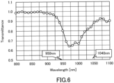
- the present inventors obtained a finding that the transmittance depends on the glucose concentration in the near-infrared light wavelength band of 800 to 1100 nm, as a result of creating blood with different glucose concentration by adding glucose to the blood and performing a spectroscopic analysis.
- the present inventors found out the usefulness of using a wavelength band of 800 to 950 nm as a wavelength for measuring glucose concentration.
- the blood glucose measurement device comprises: a light source that irradiates light having a wavelength selected from a wavelength band of 800 to 950 nm; a sensor that receives light transmitted, reflected, or scattered in a living body and outputs information according to the amount of light received; and a blood glucose acquisition unit that acquires the blood glucose in the blood in the living body based on the information obtained by the sensor.
- a blood glucose measurement device capable of measuring a blood glucose in the blood while suppressing the influence of light absorption or the like due to water in the living body.
- the senor may be an image sensor having a plurality of pixels arranged in an array in a two-dimensional plane.
- a blood glucose measurement device capable of measuring a blood glucose in the blood based on the image information obtained from an image sensor.
- an SN ratio of the sensor may be 60 dB or more.
- a blood glucose measurement device capable of measuring the blood glucose in the blood with high accuracy and reliability while suppressing the influence of light absorption by water in the living body.
- a saturation charges of the sensor may be 1,000,000 or more.
- a blood glucose measurement device capable of measuring the blood glucose in the blood with high accuracy and reliability while suppressing the influence of light absorption by water in the living body.
- a photodiode quantum efficiency of the sensor with respect to a near-infrared light irradiated from the light source may be 50% or more.
- a blood glucose measurement device capable of measuring the blood glucose in the blood with high accuracy and reliability while suppressing the influence of light absorption by water in the living body.
- the blood glucose measurement device comprises: a light source that irradiates near-infrared light; a sensor that receives light transmitted, reflected, or scattered in a living body and outputs information according to the amount of received light; and a blood glucose acquisition unit that acquires the blood glucose in the blood in the body, wherein the wavelength of the near-infrared light irradiated from the light source is selected from the wavelength band of 800 to 950 nm.
- FIG. 1 is a block diagram showing an example of the configuration of the blood glucose measurement device according to the present embodiment.
- the blood glucose measurement device 10 shown in FIG. 1 includes a light source 11, a filter 12, a sensor 13, a signal processing unit 14, a display unit 15, a data storage unit 16, an operation unit 17, and a control unit 18.
- the light source 11 is a device that emits light used for measuring the blood glucose of blood in a living body.
- the light source 11 in the present embodiment is configured to be capable of irradiating light having a wavelength suitable for measuring the blood glucose.
- the light source 11 is configured to be capable of irradiating light having a wavelength selected from a wavelength band of 800 to 950 nm.
- the light source 11 is not particularly limited, but for example, a laser device capable of irradiating laser light can be used, and a GaAs (gallium arsenide) laser diode can be used as an example.
- the light source 11 in the present embodiment is preferably capable of irradiating a high amount of light (high illuminance), and for example, a laser device having a maximum output of about 500 mW may be used.
- the sensor 13 is arranged in the subject S at a position where it can receive the transmitted, reflected, or scattered light.
- the sensor 13 has a function of outputting an electric signal corresponding to the received light.
- a CMOS image sensor capable of outputting an electric signal that can be finally processed as image information from the received light can constitute the image sensor 13.
- the CMOS sensor applicable to the present invention preferably satisfies a specific condition, and the details thereof will be described later.
- a filter 12 that transmits only the light having a specific wavelength may be provided in a front stage of the light receiving portion of the sensor 13.
- the light source 11 is configured to be capable of irradiating light having a wavelength selected from the wavelength band of 800 to 950 nm.
- the filter 12 that transmits only the light having the same wavelength as the light irradiated by the light source 11 only the light having the same wavelength as the light irradiated by the light source 11 may reach the sensor 13 in the rear stage.
- the transmission characteristics of the filter 12 may be adjusted so that the light having only a part of the wavelength band included in the light irradiated by the light source 11 reaches.
- the blood glucose acquisition unit 14a can acquire the blood glucose of the subject S from one image information, but the blood glucose acquisition unit 14a may acquire the blood glucose of the subject S based on a plurality of image information (for example, a plurality of frames constituting the image). For example, the blood glucose acquisition unit 14a may acquire a blood glucose from each of a plurality of image information and calculate an average value or a median value thereof.
- a part of the blood glucose measurement device 10 may be configured by a computer such as a personal computer.
- the signal processing unit 14 and the control unit 18 can be realized by a CPU that executes a program described to perform a desired operation.
- the display unit 15, the data storage unit 16, and the operation unit 17 can be realized by a monitor connected to a computer, an auxiliary storage device such as an HDD, a mouse, a keyboard, or the like, respectively.
- the CMOS image sensors described in Non-Patent Document 1 and Non-Patent Document 2 can be preferably used.
- the disclosures of Non-Patent Document 1 and Non-Patent Document 2 are incorporated herein by reference.
- Non-Patent Document 1 and Non-Patent Document 2 describe CMOS image sensors in which a horizontal overflow accumulation trench capacity is mounted on each pixel on a p-type Si substrate having a low impurity concentration in which the impurity concentration is reduced to about 10 12 cm -3 , and a high number of saturated electrons (>10 million) with high quantum efficiency in the near-infrared region is combined.
- This CMOS image sensor achieves a linear response to light from low to high illuminance, a saturation charge number of 24,300,000, a signal-to-noise ratio (SN ratio) of 71.3 dB, and high quantum efficiency in the wide light wavelength band of 200 to 1100 nm.
- Non-Patent Document 1 the outline and features of the CMOS image sensors described in Non-Patent Document 1 and Non-Patent Document 2 will be described with reference to FIGS. 2 to 4 .
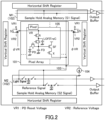
- FIG. 2 is a diagram showing an example of an optical sensor unit of a CMOS image sensor that can be suitably used in the present embodiment.
- FIG. 2 schematically shows an equivalent circuit diagram including a pixel circuit and a read circuit for one row as a part of the optical sensor unit of the CMOS image sensor.
- the optical sensor unit of the CMOS image sensor shown in FIG. 2 is constituted by a pixel array unit 101 and a reading unit 102 including sample hold analog memories M1 and M2.
- the pixels 105 included in the pixel array unit 101 and the reading unit 102 are electrically connected to each other through the pixel train output signal line 103.
- a current source 104 composed of, for example, a MOS transistor is connected to the pixel train output signal line 103.
- Pixel 105 is constituted by an embedded completely depleted photodiode PD, that generates an optical charge according to the intensity of light, a transfer gate T that transfers the optical charge from the photodiode PD, a floating diffusion capacitance FD in which the optical charge is transferred through the transfer gate T, a horizontal overflow storage trench capacity LOFITreC which stores the optical charge overflowing from the photodiode PD during the optical charge storage operation, a connection switch S that electrically couples or divides the floating diffusion capacitance FD and the horizontal overflow storage trench capacity LOFITreC, a reset gate R for discharging the optical charge inside the horizontal overflow storage trench capacity LOFITreC and floating diffusion capacitance FD which is formed to connect directly to the horizontal overflow storage trench capacitance LOFITreC and to the floating diffusion capacitance FD via connection switch S, a source follower amplifier SF that amplifies and converts the optical charge in the horizontal overflow storage trench capacity LOFITreC and floating diffusion capacitance
- Sample hold analog memories M1 and M2 are connected to the pixel train output signal line 103.
- the sample hold analog memory M1 is a train circuit unit that outputs a voltage signal in which the optical charge transferred into the floating diffusion capacitance FD is converted.
- the sample hold analog memory M1 is configured to output a reference signal including thermal noise taken in when the floating diffusion capacitance FD is reset to a predetermined voltage and a voltage signal in which a voltage signal based on the amount of optical charge is superimposed on the thermal noise, to remove the fixed pattern noise and thermal noise caused by variation in the characteristics of the source follower amplifier SF due to the operating amplifier outside the pixel chip, so that a high-sensitivity signal S1 that captures light emission under low illuminance can be obtained.
- the sample hold analog memory M2 is configured to outputs a high saturation signal S2 indicating the difference between the signal voltage level after the storage period and the reference voltage VR2, by setting the voltage level of the reference voltage VR2, which is switched by the selection switch SS as described above, to an intermediate value between the saturation level and the signal level.
- M2 is configured to be able to output a high saturation signal S2 capable of capturing a minute change in the amount of light under high illuminance with high accuracy, by amplifying the signal using a gain amplifier or the like in the signal readout circuit in the subsequent stage.
- the optical sensor unit of the CMOS image sensor shown in FIG. 2 can operate in two operation modes, which are an operation mode that supports a wide dynamic range (LOFIC operation mode), and an operation mode that can capture changes in the amount of light in the high illuminance region (Dual VR operation mode).
- the optical sensor unit of the CMOS image sensor can output the above-mentioned high-sensitivity signal S1 and high-saturation signal S2, can achieve a wide dynamic range with a single exposure, and is adaptable to luminescence imaging, which captures minute luminescence in low light conditions, and to imaging targets with large differences in brightness and darkness.
- the optical sensor portion of the CMOS image sensor is specialized for, for example, absorption imaging under high emittance, and it is possible to clearly capture minute changes in the amount of light even under high emittance.
- This CMOS image sensor achieves high quantum efficiency in the wide light wavelength band of 200 to 1100 nm.
- This CMOS image sensor adopts a surface irradiation structure so that near-infrared light with a long wavelength does not affect the operation of the transistor in the pixel, and in addition, in order to achieve both high sensitivity and high light resistance to ultraviolet light, a p + layer having a steep density profile is formed on the surface of the photodiode PD as shown in FIG. 4 .
- a photodiode PD and a transistor portion are arranged on the surface of the Si substrate to form a pixel array.
- the size of the pixel array is 2.1 mm in the horizontal direction ⁇ 2.1 mm in the vertical direction
- the number of pixels is 128 in the horizontal direction ⁇ 128 in the vertical direction
- the pixel size is 16 ⁇ m in the horizontal direction ⁇ 16 ⁇ m in the vertical direction
- the opening ratio is 52.8%.
- a horizontal overflow storage trench capacity LOFITreC is provided in each pixel.
- the horizontal overflow storage trench capacity LOFITreC is a capacitor containing a three-dimensional structure, and it is composed of a trench (shallow groove) formed in the pixel of the Si substrate, an oxide film formed along the trench, and a doped poly-Si electrode node embedded in the trench.
- Leakage current may occur between the embedded n-type layer of the photodiode PD and the inverted layer induced by the horizontal overflow storage trench capacity LOFITreC.
- a deep p-well DPW
- the concentration of DPW is optimized so as to be able to obtain a uniform capacitance over the signal voltage range of the horizontal overflow storage trench capacitance LOFITreC (For example, 0.5-3.0 V).
- the CMOS image sensor is so configured that the charge overflowing from the photodiode PD and the floating diffusion capacitance FD is stored in the electrode node in the horizontal overflow storage trench capacity LOFITreC.
- near-infrared light has a large penetration depth from the surface of the photodiode PD, so that, in order to detect near-infrared light, it is necessary to accumulate and detect the optical charge photoelectrically converted in the deep portion of the photodiode PD.
- a potential gradient is formed in the p-well and DPW under the region of the transistor portion.
- the inverted layer and the n + layer induced at the Si substrate side interface of the horizontal overflow storage trench capacity LOFITreC are connected to the ground (GND).
- a negative potential for example, a potential of about 3.0 V at maximum
- a negative potential may be applied to the back surface side (lower side of FIGS. 3 and 4 ) of the Si substrate to form an electric field in the depth direction of the Si substrate.
- the thickness of the Si substrate may be reduced.
- the CMOS image sensor described above with reference to FIGS. 2 to 4 describes the CMOS image sensor described in Non-Patent Document 1 and Non-Patent Document 2.
- the CMOS image sensors described in Non-Patent Document 1 and Non-Patent Document 2 can be preferably used.
- the present invention is not limited to the use of the CMOS image sensor described in Non-Patent Document 1 and Non-Patent Document 2, and for example, a sensor satisfying the specific conditions listed below can be applied to the present invention.
- the sensor 13 applicable to the present invention is a sensor having a saturation charge number of 1,000,000 or more, preferably a saturation charge number of 3,200,000 or more, and particularly preferably a saturation charge number of 10,000,000 or more. Further, the sensor 13 applicable to the present invention has an SN ratio of 60 dB or more (corresponding to a saturation charge number of about 1,000,000 or more), particularly preferably 65 dB or more (corresponding to a saturation charge number of about 3,200,000 or more), and particularly preferably 70 dB or more (corresponding to a saturation charge number about 10,000,000 or more).
- a sensor having a saturation charge number or an SN ratio satisfying the above conditions is suitable because it has a high SN ratio performance and can capture a minute difference in the amount of light under high illuminance.
- the senor 13 according to the present invention can clearly image a fluid moving in a living body (for example, blood cells in the blood) at a high frame rate. Since a sensor having a saturation charge number or an SN ratio satisfies the above conditions can increase a signal amount per frame, it is preferable , since even when the frame rate is increased (for example, 30 fps or more), it is possible to output a clear image that captures a minute difference in the amount of light under high illuminance, with the result that it becomes possible to measure biological information with high accuracy.
- the light amount of the light source 11 in addition to the sensor having a saturation charge number of 1,000,000 or more or a sensor having an SN ratio of 60 dB or more as described above, it is preferable to use a high output light source 11 capable of emitting a high amount of light corresponding to this sensor.
- the sensor 13 it is preferable to apply a sensor having a capacitor with a three-dimensional structure in the pixel and capable of accumulating light charges.
- the saturation charge number can be increased, by using a capacitor having a three-dimensional structure in the pixel.
- a capacitor having a three-dimensional structure for example, a silicon trench structure can be adopted, and further, the leakage current can be reduced by adopting a configuration in which the light charge is accumulated in the trench-embedded electrode node.
- the capacitor including the three-dimensional structure is not limited to the silicon trench structure, and a metal-insulating film-metal type capacitor having a three-dimensional structure formed in the wiring layer may be used.
- the sensor 13 it is preferable to apply a sensor having a capacitor having a uniform capacitance in a specific signal voltage range.
- the specific signal voltage range is preferably, for example, 0.5 to 3.0 V, and it is preferable that a linear response can be obtained with respect to the amount of light received in the specific signal voltage range.
- the senor 13 it is preferable to apply a sensor capable of applying an electric potential to a substrate to form an electric field in the depth direction of the substrate. As a result, it is possible to suppress crosstalk between pixels of signal charges (light charges) for near-infrared light having a large penetration length and improve the resolution of near-infrared light.
- the sensor When measuring the blood glucose of the blood in the blood vessel non-invasively, the sensor receives light transmitted, reflected, or scattered by irradiating light from the outside of the skin, and the blood glucose is measured based on the amount of received light.
- Near-infrared light radiated from the outside of the skin toward the inside of the living body passes through the epidermis and reaches the capillaries in the dermis and the blood vessel in the subcutaneous tissue.
- body fluid is contained inside and outside of the cells constituting the epidermis and dermis, and the amount of light received by the sensor may decrease due to the influence of the absorption of light by the body fluid. For this reason, it is desirable to use light having a wavelength that is less absorbed by body fluid.
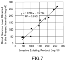
- the present inventors conducted an experiment in which the blood having an adjusted glucose concentration was put into a cell, irradiated the cell with light to measure the blood glucose in the blood, using an LED capable of irradiating near-infrared light of 810 nm. The results of this experiment are shown in FIG. 7 .
Landscapes
- Health & Medical Sciences (AREA)
- Life Sciences & Earth Sciences (AREA)
- Physics & Mathematics (AREA)
- Medical Informatics (AREA)
- Surgery (AREA)
- Biophysics (AREA)
- Pathology (AREA)
- Engineering & Computer Science (AREA)
- Biomedical Technology (AREA)
- Heart & Thoracic Surgery (AREA)
- Veterinary Medicine (AREA)
- Molecular Biology (AREA)
- Optics & Photonics (AREA)
- Animal Behavior & Ethology (AREA)
- General Health & Medical Sciences (AREA)
- Public Health (AREA)
- Spectroscopy & Molecular Physics (AREA)
- Emergency Medicine (AREA)
- Measurement Of The Respiration, Hearing Ability, Form, And Blood Characteristics Of Living Organisms (AREA)
- Investigating Or Analysing Materials By Optical Means (AREA)
Applications Claiming Priority (2)
| Application Number | Priority Date | Filing Date | Title |
|---|---|---|---|
| JP2021025482 | 2021-02-19 | ||
| PCT/JP2022/005643 WO2022176801A1 (fr) | 2021-02-19 | 2022-02-14 | Instrument de mesure de la glycémie |
Publications (2)
| Publication Number | Publication Date |
|---|---|
| EP4295768A1 true EP4295768A1 (fr) | 2023-12-27 |
| EP4295768A4 EP4295768A4 (fr) | 2025-01-15 |
Family
ID=82930595
Family Applications (1)
| Application Number | Title | Priority Date | Filing Date |
|---|---|---|---|
| EP22756119.8A Withdrawn EP4295768A4 (fr) | 2021-02-19 | 2022-02-14 | Instrument de mesure de la glycémie |
Country Status (6)
| Country | Link |
|---|---|
| US (1) | US20240298931A1 (fr) |
| EP (1) | EP4295768A4 (fr) |
| JP (1) | JPWO2022176801A1 (fr) |
| CN (1) | CN116867432A (fr) |
| TW (1) | TW202302040A (fr) |
| WO (1) | WO2022176801A1 (fr) |
Families Citing this family (1)
| Publication number | Priority date | Publication date | Assignee | Title |
|---|---|---|---|---|
| TWI907306B (zh) * | 2025-04-30 | 2025-12-01 | 台亞半導體股份有限公司 | 複合波長光源的血糖偵測模組及其穿戴裝置 |
Family Cites Families (17)
| Publication number | Priority date | Publication date | Assignee | Title |
|---|---|---|---|---|
| US5086229A (en) * | 1989-01-19 | 1992-02-04 | Futrex, Inc. | Non-invasive measurement of blood glucose |
| CA2259254C (fr) * | 1996-07-08 | 2008-02-19 | Animas Corporation | Capteur implantable et systeme de mesure et de controle in vivo de taux de constituants de fluides |
| JPH11178813A (ja) * | 1997-12-22 | 1999-07-06 | Matsushita Electric Works Ltd | グルコース濃度の定量方法及びその装置 |
| US6477393B1 (en) * | 2000-07-19 | 2002-11-05 | Trw Inc. | Non-invasive blood glucose measurement techniques |
| JP3884036B2 (ja) * | 2004-08-25 | 2007-02-21 | 株式会社日立製作所 | 血糖値測定装置 |
| JPWO2006040841A1 (ja) * | 2004-10-15 | 2008-05-15 | 長崎県 | 血糖値の非侵襲測定装置 |
| EP2628446A4 (fr) * | 2010-10-14 | 2017-01-04 | Hitachi, Ltd. | Équipement pour l'acquisition et l'analyse de données in vivo |
| GB2489717B (en) * | 2011-04-05 | 2017-10-18 | Electronic Medical Solutions Ltd | Device and method for the detection of blood analytes |
| JP2014008139A (ja) * | 2012-06-28 | 2014-01-20 | Tauzaa Kenkyusho:Kk | 血糖値測定装置 |
| JP6291874B2 (ja) * | 2014-01-31 | 2018-03-14 | セイコーエプソン株式会社 | 生体情報測定装置及び生体情報測定方法 |
| KR102223279B1 (ko) * | 2014-07-08 | 2021-03-05 | 엘지전자 주식회사 | 측정장치 및 이를 구비하는 웨어러블 디바이스 |
| RU2574571C1 (ru) * | 2014-12-22 | 2016-02-10 | Эдвард Владимирович Крыжановский | Способ неинвазивного определения концентрации глюкозы в крови |
| JP6507670B2 (ja) * | 2015-01-27 | 2019-05-08 | セイコーエプソン株式会社 | 情報取得機器 |
| CN107865664A (zh) * | 2017-09-22 | 2018-04-03 | 郜键 | 一种激光成像非采血式血糖检测方法 |
| CN108152244A (zh) * | 2017-12-15 | 2018-06-12 | 京东方科技集团股份有限公司 | 一种血糖检测装置和血糖检测方法 |
| DE102019112346A1 (de) * | 2019-05-10 | 2020-11-12 | TRUMPF Venture GmbH | System zur Messung des Vorhandenseins und/oder der Konzentration einer in Körperflüssigkeit gelösten Analysesubstanz |
| CN110123339B (zh) * | 2019-05-10 | 2023-10-31 | 湖南龙罡智能科技有限公司 | 一种无创血糖测量装置与方法 |
-
2022
- 2022-02-11 TW TW111105109A patent/TW202302040A/zh unknown
- 2022-02-14 EP EP22756119.8A patent/EP4295768A4/fr not_active Withdrawn
- 2022-02-14 US US18/546,366 patent/US20240298931A1/en active Pending
- 2022-02-14 JP JP2023500821A patent/JPWO2022176801A1/ja active Pending
- 2022-02-14 WO PCT/JP2022/005643 patent/WO2022176801A1/fr not_active Ceased
- 2022-02-14 CN CN202280014689.6A patent/CN116867432A/zh active Pending
Also Published As
| Publication number | Publication date |
|---|---|
| TW202302040A (zh) | 2023-01-16 |
| JPWO2022176801A1 (fr) | 2022-08-25 |
| WO2022176801A1 (fr) | 2022-08-25 |
| EP4295768A4 (fr) | 2025-01-15 |
| CN116867432A (zh) | 2023-10-10 |
| US20240298931A1 (en) | 2024-09-12 |
Similar Documents
| Publication | Publication Date | Title |
|---|---|---|
| US10652482B2 (en) | Imaging apparatus including light source that emits pulsed light, image sensor, and control circuit | |
| US11864877B2 (en) | Health monitoring device including pinned photodiode | |
| JP5422990B2 (ja) | 生体成分検出装置 | |
| CN103260515B (zh) | 生物体信息获取解析装置 | |
| TWI734748B (zh) | 用於生命期成像及偵測應用之感測器及裝置 | |
| JP2010142596A5 (fr) | ||
| EP1872101B1 (fr) | Capteur permettant d'eliminer des composants indesirables et procede de mesure utilisant ce capteur | |
| EP3893754B1 (fr) | Capteur non effractif du glucose | |
| EP4295768A1 (fr) | Instrument de mesure de la glycémie | |
| EP4297094A1 (fr) | Dispositif de mesure d'informations biométriques | |
| JP4721147B1 (ja) | 生体成分検出装置 | |
| Ng et al. | A Complementary Metal–Oxide–Semiconductor Image Sensor for On-Chip in Vitro and in Vivo Imaging of the Mouse Hippocampus | |
| CN114497102B (zh) | 用于血氧检测的像素单元及包括其的无创血氧检测仪 | |
| US20250281073A1 (en) | Chemical Detection Using Single-Photon Avalanche Diodes | |
| WO2025238421A1 (fr) | Module de capteur optique | |
| CN118382391A (zh) | 光学传感器模块 |
Legal Events
| Date | Code | Title | Description |
|---|---|---|---|
| STAA | Information on the status of an ep patent application or granted ep patent |
Free format text: STATUS: THE INTERNATIONAL PUBLICATION HAS BEEN MADE |
|
| PUAI | Public reference made under article 153(3) epc to a published international application that has entered the european phase |
Free format text: ORIGINAL CODE: 0009012 |
|
| STAA | Information on the status of an ep patent application or granted ep patent |
Free format text: STATUS: REQUEST FOR EXAMINATION WAS MADE |
|
| 17P | Request for examination filed |
Effective date: 20230814 |
|
| AK | Designated contracting states |
Kind code of ref document: A1 Designated state(s): AL AT BE BG CH CY CZ DE DK EE ES FI FR GB GR HR HU IE IS IT LI LT LU LV MC MK MT NL NO PL PT RO RS SE SI SK SM TR |
|
| DAV | Request for validation of the european patent (deleted) | ||
| DAX | Request for extension of the european patent (deleted) | ||
| A4 | Supplementary search report drawn up and despatched |
Effective date: 20241213 |
|
| RIC1 | Information provided on ipc code assigned before grant |
Ipc: A61B 5/145 20060101ALI20241209BHEP Ipc: A61B 5/1455 20060101AFI20241209BHEP |
|
| STAA | Information on the status of an ep patent application or granted ep patent |
Free format text: STATUS: THE APPLICATION IS DEEMED TO BE WITHDRAWN |
|
| 18D | Application deemed to be withdrawn |
Effective date: 20250710 |