EP4296419B1 - Wäscheverarbeitungsvorrichtung und verfahren zur steuerung davon - Google Patents
Wäscheverarbeitungsvorrichtung und verfahren zur steuerung davon Download PDFInfo
- Publication number
- EP4296419B1 EP4296419B1 EP23209148.8A EP23209148A EP4296419B1 EP 4296419 B1 EP4296419 B1 EP 4296419B1 EP 23209148 A EP23209148 A EP 23209148A EP 4296419 B1 EP4296419 B1 EP 4296419B1
- Authority
- EP
- European Patent Office
- Prior art keywords
- drying
- washing machine
- washing
- machine
- user input
- Prior art date
- Legal status (The legal status is an assumption and is not a legal conclusion. Google has not performed a legal analysis and makes no representation as to the accuracy of the status listed.)
- Active
Links
Images




Classifications
-
- D—TEXTILES; PAPER
- D06—TREATMENT OF TEXTILES OR THE LIKE; LAUNDERING; FLEXIBLE MATERIALS NOT OTHERWISE PROVIDED FOR
- D06F—LAUNDERING, DRYING, IRONING, PRESSING OR FOLDING TEXTILE ARTICLES
- D06F29/00—Combinations of a washing machine with other separate apparatus in a common frame or the like, e.g. with rinsing apparatus
- D06F29/005—Combinations of a washing machine with other separate apparatus in a common frame or the like, e.g. with rinsing apparatus the other separate apparatus being a drying appliance
-
- D—TEXTILES; PAPER
- D06—TREATMENT OF TEXTILES OR THE LIKE; LAUNDERING; FLEXIBLE MATERIALS NOT OTHERWISE PROVIDED FOR
- D06F—LAUNDERING, DRYING, IRONING, PRESSING OR FOLDING TEXTILE ARTICLES
- D06F34/00—Details of control systems for washing machines, washer-dryers or laundry dryers
- D06F34/04—Signal transfer or data transmission arrangements
- D06F34/05—Signal transfer or data transmission arrangements for wireless communication between components, e.g. for remote monitoring or control
-
- D—TEXTILES; PAPER
- D06—TREATMENT OF TEXTILES OR THE LIKE; LAUNDERING; FLEXIBLE MATERIALS NOT OTHERWISE PROVIDED FOR
- D06F—LAUNDERING, DRYING, IRONING, PRESSING OR FOLDING TEXTILE ARTICLES
- D06F34/00—Details of control systems for washing machines, washer-dryers or laundry dryers
- D06F34/28—Arrangements for program selection, e.g. control panels therefor; Arrangements for indicating program parameters, e.g. the selected program or its progress
-
- D—TEXTILES; PAPER
- D06—TREATMENT OF TEXTILES OR THE LIKE; LAUNDERING; FLEXIBLE MATERIALS NOT OTHERWISE PROVIDED FOR
- D06F—LAUNDERING, DRYING, IRONING, PRESSING OR FOLDING TEXTILE ARTICLES
- D06F2101/00—User input for the control of domestic laundry washing machines, washer-dryers or laundry dryers
- D06F2101/14—Time settings
-
- D—TEXTILES; PAPER
- D06—TREATMENT OF TEXTILES OR THE LIKE; LAUNDERING; FLEXIBLE MATERIALS NOT OTHERWISE PROVIDED FOR
- D06F—LAUNDERING, DRYING, IRONING, PRESSING OR FOLDING TEXTILE ARTICLES
- D06F2101/00—User input for the control of domestic laundry washing machines, washer-dryers or laundry dryers
- D06F2101/20—Operation modes, e.g. delicate laundry washing programs, service modes or refreshment cycles
-
- D—TEXTILES; PAPER
- D06—TREATMENT OF TEXTILES OR THE LIKE; LAUNDERING; FLEXIBLE MATERIALS NOT OTHERWISE PROVIDED FOR
- D06F—LAUNDERING, DRYING, IRONING, PRESSING OR FOLDING TEXTILE ARTICLES
- D06F2103/00—Parameters monitored or detected for the control of domestic laundry washing machines, washer-dryers or laundry dryers
- D06F2103/40—Opening or locking status of doors
-
- D—TEXTILES; PAPER
- D06—TREATMENT OF TEXTILES OR THE LIKE; LAUNDERING; FLEXIBLE MATERIALS NOT OTHERWISE PROVIDED FOR
- D06F—LAUNDERING, DRYING, IRONING, PRESSING OR FOLDING TEXTILE ARTICLES
- D06F2105/00—Systems or parameters controlled or affected by the control systems of washing machines, washer-dryers or laundry dryers
- D06F2105/50—Starting machine operation, e.g. delayed start or re-start after power cut
-
- D—TEXTILES; PAPER
- D06—TREATMENT OF TEXTILES OR THE LIKE; LAUNDERING; FLEXIBLE MATERIALS NOT OTHERWISE PROVIDED FOR
- D06F—LAUNDERING, DRYING, IRONING, PRESSING OR FOLDING TEXTILE ARTICLES
- D06F2105/00—Systems or parameters controlled or affected by the control systems of washing machines, washer-dryers or laundry dryers
- D06F2105/58—Indications or alarms to the control system or to the user
-
- D—TEXTILES; PAPER
- D06—TREATMENT OF TEXTILES OR THE LIKE; LAUNDERING; FLEXIBLE MATERIALS NOT OTHERWISE PROVIDED FOR
- D06F—LAUNDERING, DRYING, IRONING, PRESSING OR FOLDING TEXTILE ARTICLES
- D06F34/00—Details of control systems for washing machines, washer-dryers or laundry dryers
- D06F34/04—Signal transfer or data transmission arrangements
-
- D—TEXTILES; PAPER
- D06—TREATMENT OF TEXTILES OR THE LIKE; LAUNDERING; FLEXIBLE MATERIALS NOT OTHERWISE PROVIDED FOR
- D06F—LAUNDERING, DRYING, IRONING, PRESSING OR FOLDING TEXTILE ARTICLES
- D06F58/00—Domestic laundry dryers
- D06F58/32—Control of operations performed in domestic laundry dryers
- D06F58/34—Control of operations performed in domestic laundry dryers characterised by the purpose or target of the control
- D06F58/36—Control of operational steps, e.g. for optimisation or improvement of operational steps depending on the condition of the laundry
Definitions
- a drying machine may include a drum that is rotatably installed, and may dry an object to be dried (laundry) by injecting high-temperature dry hot air into the drum while the drum is rotating.
- the drying machine may perform a drying process for drying the object to be dried.
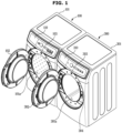
- FIG. 1 is a view illustrating that a washing machine is arranged horizontally with a drying machine according to an embodiment.
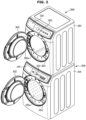
- FIG. 2 is a view illustrating that a washing machine is arranged vertically with a drying machine according to an embodiment.
- the drying machine 300 may be disposed on the washing machine 100 (vertical).
- the washing machine 100 usually washes laundry (for example, clothes or shoes) using water, and thus a weight of the washing machine 100 may increase significantly during a washing operation.
- the drying machine 300 only dries objects to be dried (e.g., clothing or shoes, etc.) using high-temperature dry hot air, so that a weight of the drying machine 300 does not change significantly during a drying operation.
- the relatively light drying machine 300 may be placed on top of the washing machine 100.
- the drying machine 300 is disposed on top of the washing machine 100, a space occupied by the washing machine 100 and the drying machine 300 may be similar to a case where the washing machine 100 is used alone. In other words, the user's living space may not be significantly reduced due to the drying machine 300.
- the control panel of the drying machine 300 is placed at a high position. As a result, some of the users may have difficulty using the control panel of the drying machine 300.
- the tub 120 may be provided inside the cabinet 101 and may accommodate water for washing and/or rinsing.
- the tub 120 may include a tub front part 121 having an opening 121a formed at a front surface thereof, and a tub rear part 122 having a cylindrical shape with a closed rear surface thereof.
- the drum 130 is rotatably provided in the tub 120 and may accommodate laundry.
- the drum 130 may include a cylindrical drum body 131, a drum front part 132 provided at the front of the drum body 131, and a drum rear part 133 provided at the rear of the drum body 131.
- the inner surface of the drum body 131 provides a through hole 131a connecting the inside of the drum 130 and the inside of the tub 120 and a lifter 131b for raising laundry to an upper portion of the drum 130 during the rotation of the drum 130.
- the drum front part 132 is provided with an opening 132a for injecting laundry into the drum 130 or withdrawing laundry from the drum 130.
- the drum rear part 133 may be connected to a shaft 141 of the drum motor 140 that rotates the drum 130.
- the drum motor 140 is provided outside the tub rear part 122 of the tub 120 and is connected to the drum rear part 133 of the drum 130 through the shaft 141.
- the shaft 141 penetrates the tub rear part 122 and is rotatably supported by the bearing 122a provided in the tub rear part 122.
- the drum motor 140 includes a stator 142 fixed to the outside of the tub rear part 122, and a rotor 143 rotatably provided and connected to the shaft 141.
- the rotor 143 may rotate through magnetic interaction with the stator 142, and the rotation of the rotor 143 may be transmitted to the drum 130 through the shaft 141.
- the drum motor 140 may include, for example, a BrushLess Direct Current Motor (BLDC Motor) or a Permanent Synchronous Motor (PMSM).
- BLDC Motor BrushLess Direct Current Motor
- PMSM Permanent Synchronous Motor
- the water supplier 150 is provided above the tub 120 and may supply water to the tub 120 / the drum 130.
- the water supplier 150 includes a water supply conduit 151 connected to an external water supply source for supplying water to the tub 120, and a water supply valve 152 provided on the water supply conduit 151.
- the water drain 160 is provided below the tub 120 and may discharge the water contained in the tub 120 / the drum 130 to the outside.
- the detergent supplier 170 may include the detergent compartment 171 for storing the detergent and a mixing conduit 172 connecting the detergent compartment 171 with the tub 120.
- the washing machine 100 may further include the following electrical components as well as mechanical components described with reference to FIG. 3 .
- the washing machine 100 may include the drum motor 140, the water supply valve 152, the drain pump 162, the door switch 103, the door lock 104, the control panel 110, a communication device 180, and a controller 190.
- the door switch 103 may detect a state in which the door 102 is closed and a state in which the door 102 is open, respectively. For example, the door switch 103 may be opened (off) when the door 102 is open, and the door switch 103 may be closed (on) when the door 102 is closed. The door switch 103 may provide a signal indicating the closed state of the door 102 or a signal indicating the open state of the door 102 to the controller 190.
- the door lock 104 may lock the door 102 in response to a lock signal from the controller 190.
- the controller 190 may control the door lock 104 to lock the door 102.
- the control panel 110 may include the user inputter for obtaining the user input, and the display for displaying the washing setting and/or washing operation information in response to the user input.
- the control panel 110 may provide an interface (hereinafter referred to as 'user interface') for the user and the washing machine 100 to interact.
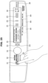
- the control panel 110 may include a washer power button 211 for obtaining the user input for powering on the washing machine 100 or obtaining the user input for powering off the washing machine 100, as illustrated in FIG. 5 .
- the washing machine 100 may be placed in three states including an "off state,” a “standby state,” and an “on state,” and may perform different operations depending on a power state of the washing machine 100.
- the washing machine 100 may be placed in the "off state" where a plug is not inserted into a power socket. In the "off state,” no power is supplied to a display device, and the washing machine 100 may not perform any operation.
- the washing machine 100 may be placed in the "standby state” in which the plug is inserted into the power socket and the user's power-on command (for example, touching a power button) is not input.
- the “standby state” some of the components included in the washing machine 100 may be powered.
- power may be supplied to a part of the control panel 110, the communication device 180, and the controller 190.
- the washing machine 100 When the washer power button 211 is touched or pressed by the user while the plug of the washing machine 100 is inserted into the socket, the washing machine 100 may be switched from the “standby state” to the “on state” and the power is supplied to all the components included in the washing machine 100, and all functions of the washing machine 100 may be activated.
- the washer power button 211 When the washer power button 211 is touched or pressed by the user in the “on state,” the washing machine 100 may be switched from the “on state” to the "standby state” and many functions of the washing machine 100 may be deactivated.
- the washer power button 211 may include a tact switch, a push switch, a slide switch, a toggle switch, a micro switch, or a touch switch.
- the washer power button 211 may include a first touch switch 211a for obtaining the user's touch input, and the first touch switch 211a may be connected to the controller 190.
- the washer power button 211 may display the power state of the washing machine 100. For example, in the "on state,” the washer power button 211 may emit light, and in the 'standby state,' the washer power button 211 may not emit light.
- the washer power button 211 may further include a first light emitting diode that emits light depending on, for example, the power state of the washing machine 100.
- the washing machine 100 may provide a first user interface for controlling the washing machine 100 and a second user interface for controlling the drying machine 300 using one of the control panels 110.
- the washing machine 100 may operate in a dryer control mode for obtaining the user input to the drying machine 300 or in a washer control mode for obtaining the user input to the washing machine 100 in order to provide a plurality of user interfaces using one of the control panels 110.
- the control panel 110 may further include a drying operation button 231 that obtains the user input for starting the drying operation of the drying machine 300 or pausing the drying operation, and a washing operation button 232 that obtains the user input for starting the washing operation of the washing machine 100 or pausing the washing operation, as illustrated in FIG. 5 .
- the first setting button 261 may obtain the user input for selecting drying information in the dryer control mode and the user input for selecting the washing temperature in the washer control mode.
- the first setting display 271 may display the drying information selected through the first setting button 261 in the dryer control mode and the washing temperature selected through the first setting button 261 in the washer control mode.
- the first setting button 261 may display text or symbol meaning 'degree of drying' in the dryer control mode, and text or symbol meaning 'washing temperature' in the washer control mode.
- text or symbol meaning 'degree of drying' may be displayed on a part of the first setting button 261
- the text 'washing temperature' may be displayed on another part of the first setting button 261.
- the additional setting display 291 may display whether the remote control of the drying machine 300 is activated, whether the remote control of the washing machine 100 is activated, and the like.
- the additional setting display 291 may include, for example, an LCD panel, an LED panel, and the like.
- control panel 110 may include a plurality of buttons and a plurality of displays.
- the plurality of buttons may obtain the different user inputs in the different control modes, and the plurality of displays may display different information in the different control modes.
- the communication device 180 may transmit data to the drying machine 300 and receive data from the drying machine 300.
- the communication device 180 may include a wired communication module 181 that exchanges data with the drying machine 300 by wire, a wireless communication module 182 that exchanges data with the drying machine 300 wirelessly, and a communication interface 183 that is a passage for exchanging data with the drying machine 300.
- the wired communication module 181 may exchange data with the drying machine 300 using various wired communication standards.
- the wired communication module 181 may exchange data with the drying machine 300 through a universal asynchronous receiver/transmitter (UART).
- UART universal asynchronous receiver/transmitter
- the wired communication module 181 may exchange data with the drying machine 300 using a communication standard such as RS-422 or RS-485 through the UART.
- the wired communication module 181 may exchange data with the drying machine 300 using Ethernet (IEEE 802.3 technology standard).
- the wired communication module 181 may include a communication circuit (e.g., a network interface controller) including a processor and/or memory for modulating/demodulating data for wired communication.
- a communication circuit e.g., a network interface controller
- the wireless communication module 182 may exchange data with the drying machine 300 using various wireless communication standards.
- the wireless communication module 182 may connect to a wireless repeater using Wi-Fi (WiFi TM , IEEE 802.11 technology standard) wireless communication and exchange data with the drying machine 300 through the wireless repeater.
- Wi-Fi Wi-Fi
- the Wi-Fi wireless communication may provide peer to peer communication between nodes (e.g., the display device and an audio device) without going through the wireless repeater.
- the peer to peer communication using Wi-Fi wireless communication is referred to as "WiFi P2P" or "WiFi direct.”
- the wireless communication module 182 may exchange data with the drying machine 300 using a Wi-Fi P2P communication standard.
- the wireless communication module 182 may exchange data with the drying machine 300 using Bluetooth (Bluetooth TM , IEEE 802.15.1 technology standard) or ZigBee TM (IEEE 802.15.4 technology standard) wireless communication.
- the wireless communication module 182 may exchange data with the drying machine 300 using Near Field Communication (NFC).
- NFC Near Field Communication
- the wireless communication module 182 may include a communication circuit (e.g., a wireless network interface controller) including a processor and/or memory for decoding/encoding data for wireless communication.
- a communication circuit e.g., a wireless network interface controller
- the wireless communication module 182 may be activated, and the wireless communication module 182 may exchange data with the drying machine 300 by wire through the communication interface 183 and the wireless dongle 182a.
- the communication interface 183 may have various types of connectors.
- the communication interface 183 may include a universal serial bus (USB) terminal or an RJ-45 terminal.
- USB universal serial bus
- the controller 190 may be mounted on a printed circuit board provided on the rear side of the control panel 110, for example.
- the controller 190 includes a processor 191 for generating a control signal for controlling the operation of the washing machine 100, and a memory 192 for memorizing or storing a program and data for generating a control signal for controlling the operation of the washing machine 100.
- the processor 191 and the memory 192 may be implemented as separate chips or as a single chip.
- the controller 190 may include a plurality of processors or a plurality of memories.
- the processor 191 may process data and/or signals according to a program provided from the memory 192, and provide a control signal to each component of the washing machine 100 based on a processing result.
- the processor 191 may receive the user input from the control panel 110 and process the user input.
- the processor 191 in response to the user input, may operate in the dryer control mode for controlling the drying operation of the drying machine 300 and changing the drying setting, or the washer control mode for controlling the washing operation of the washing machine 100 and changing the washing setting.
- the processor 191, based on the user input through the dryer control button 221, may provide communication data to the communication device 180 for switching to the dryer control mode and changing the drying setting of the drying machine 300.
- the processor 191, based on the user input through the washer control button 222 may switch to the washer control mode and change the washing setting of the washing machine 100.
- the processor 191 may control the control panel 110 to display the washing setting (or drying setting) and the washing operation information (or drying operation information) in response to the user input. For example, the processor 191 may control the control panel 110 to display the drying operation information or the drying settings of the drying machine 300 based on the user input through the dryer control button 221. Further, the processor 191 may control the control panel 110 to display the washing operation information or the washing settings of the washing machine 100 based on the user input through the washer control button 222.
- the processor 191 may include an operation circuit, a memory circuit, and a control circuit.
- the processor 191 may include one chip or may include a plurality of chips.
- the processor 191 may include one core or may include a plurality of cores.
- the memory 192 may include a volatile memory such as Static Random Access Memory (S-RAM) and Dynamic Random Access Memory (D-RAM), and a non-volatile memory such as Read Only Memory (ROM) and Erasable Programmable Read Only Memory (EPROM).
- S-RAM Static Random Access Memory
- D-RAM Dynamic Random Access Memory
- ROM Read Only Memory
- EPROM Erasable Programmable Read Only Memory
- the memory 192 may include one memory element or a plurality of memory elements.
- the control panel 310 including a display configured to display operation information of the drying machine 300 and a user inputter configured to obtain a user input for the drying machine 300 from the user may be provided on a front upper side of the cabinet 301.
- the control panel 310 is described in more detail below.
- An outlet 332b through which air used in drying the object to be dried is discharged may be provided in the front panel 332 of the drum 330.
- a filter 334 configured to collect foreign substances removed from the object to be dried may be installed in the outlet 332b. Accordingly, the foreign substances removed from the object to be dried may be collected by the filter 334.
- the drum 330 may receive a rotary force from the drum motor 335 and rotate.
- the drum 330 may be connected to the drum motor 335 disposed in the cabinet 301 by a belt 336.
- the drum motor 335 may provide the rotary force to the drum 330 through the belt 336.
- One or more heat sources may be provided in the drying machine 300, and the drying machine 300 may supply high-temperature air to the drum 330 through the heat sources.
- the drying machine 300 may include, as the heat sources, the heater 355 and the heat pump 360.
- drying machines including a heat pump forming a refrigerant circuit may be classified into circulating-type drying machines and air discharge-type drying machines according to the flow of air being circulated.
- the circulating-type drying machine may refer to a drying machine capable of drying an object by circulating air without discharging or sucking air.
- the air discharge-type drying machine may refer to a drying machine which sucks outside air, uses the outside air in drying, and then discharges the outside air to the outside of the drying machine.
- the drying machine 300 may include the fan 340 configured to circulate air inside the drum 330.
- the fan 340 may suck air from inside the drum 330 and discharge the air to the duct 350.
- the fan 340 may rotate by the fan motor 345.
- the heater 355 and the heat pump 360 may be provided in the duct 350 through which the air inside the drum 330 circulates.
- the heat pump 360 may include a compressor 361, a condenser 362, an evaporator 364, and an expander 363.
- the compressor 361, the condenser 362, the expander 363, and the evaporator 364 may be seated at a bottom surface of the cabinet 301.
- the compressor 361 may compress refrigerant in a gaseous state to a high-temperature, high-pressure state and discharge the gaseous refrigerant in the high-temperature, high-pressure state.
- the discharged refrigerant may be transferred to the condenser 362.
- the condenser 362 may condense the compressed gaseous refrigerant to a liquid.
- the condenser 362 may dissipate heat to surrounding portions thereof through the process of condensing the refrigerant.
- the condenser 362 may be provided in the duct 350 and heat the air through heat generated in the process of condensing the refrigerant.
- the liquid refrigerant condensed by the condenser 362 may be transferred to the expander 363.
- the expander 363 may expand the high-temperature, high-pressure liquid refrigerant condensed by the condenser 362 to the liquid refrigerant in a low-pressure state.
- the expander 363 may include an expansion valve configured to adjust a pressure difference of the refrigerant.
- the evaporator 364 may evaporate the liquid refrigerant expanded by the expander 363. As a result, the evaporator 364 may cause the low-temperature, low-pressure gaseous refrigerant to return to the compressor 361.
- the evaporator 364 may absorb heat from the surrounding portions thereof through an evaporation process in which the low-pressure liquid refrigerant is changed to the gaseous refrigerant.
- the evaporator 364 may be provided in the duct 350 and may cool air passing through the evaporator 364 in the evaporation process.
- Air around the evaporator 364 may be cooled by the evaporator 364, and, when a temperature of the air around the evaporator 364 becomes lower than the dew point, the air around the evaporator 364 may be condensed. Due to the condensation occurring around the evaporator 364, the absolute humidity of the air passing through the evaporator 364 may be lowered. In other words, the amount of water vapor contained in the air passing through the evaporator 364 may be reduced.
- the evaporator 364 may be disposed more upstream than the condenser 362 on the basis of the flow of air due to the fan 340.
- the air circulating due to the fan 340 may be dried (water vapor may be condensed) by the evaporator 364 while the air passes through the evaporator 364, and then the air may be heated by the condenser 362 while passing through the condenser 362.
- the heater 355 may assist the condenser 362 in heating the air. For example, before the condenser 362 of the heat pump 360 sufficiently heats the air in the duct 350, the heater 355 may assist the condenser 362 in heating the air in the duct 350.
- the temperature inside the drum 330 may more rapidly rise due to the heater 355 assisting the condenser 362, and the drying machine 300 may more rapidly dry the object to be dried.
- the heater 355 may be disposed more downstream than the condenser 362 on the basis of the flow of air due to the fan 340.
- the heater 355 may be implemented through a heating coil.
- the heater 355 is not limited thereto and may be implemented through various other known devices.
- FIG. 13 is a view illustrating a configuration of a drying machine according to an embodiment.
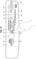
- FIG. 14 is a view illustrating a control panel included in a drying machine according to an embodiment.
- the drying machine 300 may further include the following electrical configurations as well as the mechanical configurations described in conjunction with FIGS. 11 and 12 .
- the drying machine 300 may include the drum motor 335, the fan motor 345, the heater 355, the compressor 361, the door switch 303, the door lock 304, the control panel 310, a communication device 380, and a controller 390.
- the drum motor 335 may rotate the drum 330 in response to a driving signal from the controller 390.
- the fan motor 345 may rotate the fan 340 in response to the driving signal of the controller 390.
- the heater 355 may heat air in the duct 350 in response to a heating signal from the controller 390.
- the compressor 361 may circulate the refrigerant of the heat pump 360 in response to the driving signal of the controller 390.
- the door switch 303 may detect a state in which the door 302 is closed and a state in which the door 302 is open, respectively.
- the door lock 304 may lock the door 302 in response to a lock signal from the controller 390.
- the controller 390 may control the door lock 304 to lock the door 302.
- the control panel 310 may include the user inputter for obtaining the user input, and the display for displaying the washing setting and/or the washing operation information in response to the user input.
- the control panel 310 may provide an interface (hereinafter referred to as 'user interface') for the user and the drying machine 300 to interact.
- the control panel 310 may include a dryer power button 411 for obtaining the user input for powering on the drying machine 300 or obtaining the user input for powering off the drying machine 300, as illustrated in FIG. 14 .
- the dryer power button 411 may display a power status of the drying machine 300.
- the drying machine 300 may be placed in three states including an "off state,” a “standby state,” and an “on state.”
- the operation of the drying machine 300 in each of the "off state,” the "standby state” and the “on state” may be the same as the washing machine 100.
- the control panel 310 may further include a drying operation button 431 that obtains the user input for starting the drying operation of the drying machine 300 or pausing the drying operation, as illustrated in FIG. 14 .
- the drying operation button 431 may indicate whether the drying machine 300 is operating.
- the drying operation button 431 may be the same as the drying operation button 231 of the washing machine 100 (see FIG. 5 ).
- the communication device 380 may include a wired communication module 381 that exchanges data with the washing machine 100 by wire, a wireless communication module 382 that exchanges data with the washing machine 100 wirelessly, and a communication device 383 that is a passage for exchanging data with the washing machine 100.
- the wired communication module 381, the wireless communication module 382, and the communication interface 383 may be the same as the wired communication module 181 (see FIG. 4 ), the wireless communication module 182 (see FIG. 4 ), and the communication interface 183 (see FIG. 4 ) of the washing machine 100.
- the controller 390 may be mounted on a printed circuit board provided on the rear side of the control panel 310, for example.
- the controller 190 may identify whether the communication line 181a or the wireless dongle 182a is inserted into the communication interface 183. When the communication line 181a or the wireless dongle 182a is not inserted into the communication interface 183, the controller 190 may identify that it is not connected to the drying machine 300.
- the controller 190 may transmit a request message and identify whether a response message has been received in response to the request message. When the response message is not received, the controller 190 may identify that it is not connected to the drying machine 300.
- the controller 190 may identify whether the drying machine 300 can communicate by wire or wirelessly with the drying machine 300.
- the controller 190 may identify whether the communication line 181a has been inserted into the communication interface 183 or the wireless dongle 182a has been inserted. In other words, the controller 190 may identify whether the drying machine 300 can communicate by wire or wirelessly with the drying machine 300.
- the washing machine 100 may obtain information of the drying machine 300 from the drying machine 300 (1015).
- the controller 190 may request the drying operation information and/or the drying setting information of the drying machine 300 through the communication device 180, and receive the drying operation information and/or the drying setting information of the drying machine 300 through the communication device 180. For example, the controller 190 may determine whether the drying machine 300 is in the "on state,” and when it is in the "on state,” the controller 190 may determine whether the drying machine 300 is in the drying operation. When the drying machine 300 is in the drying operation, the controller 190 may receive the time remaining until the drying operation is completed through the communication device 180.
- the controller 190 may determine whether the drying machine 300 is in the "on state,” and when it is in the "on state,” the controller 190 may determine whether the drying machine 300 is in the drying operation. When the drying machine 300 is in the drying operation, the controller 190 may identify the time remaining until the drying operation is completed.
- the washing machine 100 may identify whether the washing machine 100 is connected to the drying machine 300 after being powered on, and receive the operation information and/or the setting information of the drying machine 300 from the drying machine 300.
- the washing machine 100 may supply power to the communication device 180 at a predetermined cycle during the 'standby state,' identify whether the washing machine 100 is connected to the drying machine 300 through the communication device 180, and receive the operation information and/or the setting information of the drying machine 300 from the drying machine 300.
- the washing machine 100 may identify whether the washing machine 100 is connected to the drying machine 300 through the communication device 180 at the predetermined cycle even during the "on state” and receive the operation information and/or the setting information of the drying machine 300 from the drying machine 300.
- the washing machine 100 may operate in the washer control mode (1020).
- the controller 190 may operate in the washer control mode.
- the controller 190 may display information of the washing machine 100 and obtain the user input to the washing machine 100.
- the controller 190 may display the washing operation information and/or washing setting information and obtain the user input for controlling the washing operation and/or the washing setting.
- the controller 190 may control the control panel 110 so that the washer control button 222 emits light.
- the controller 190 may control the control panel 110 to display the washing course on the course display 251.
- the controller 190 may control the control panel 110 to display the 'washing temperature,' 'number of rinsing times,' and 'dehydrating strength' on the first setting button 261, the second setting button 262, and the third setting button 263, respectively.
- the controller 190 may control the control panel 110 to display information related to the operation of the washing machine 100 on the display, and obtain inputs related to the operation of the washing machine 100 through input buttons.
- the washing machine 100 may determine whether the washing operation is in progress (1025).
- the controller 190 may identify whether the washing machine 100 is operating or whether the washing machine 100 is not operating based on data stored in the memory 192. For example, the controller 190 may identify that the washing machine 100 is operating based on data stored in the memory 192 during the washing operation. In addition, the controller 190 may identify that the washing machine 100 is not in operation, based on data indicating that the washing is not performed in the memory 192.
- the washing machine 100 may display the washing operation information (1030), and when the washing is not in operation (NO in 1025), the washing machine 100 may display the washing setting information (1035).
- the controller 190 may display information about the washing operation of the washing machine 100 on the control panel 110. For example, the controller 190 may display the time remaining until the end of the washing operation on the course display 251.
- the washing machine 100 may display information about the washing operation or information about the washing setting of the washing machine 100 on the control panel 110 during the washer control mode.
- the washing machine 100 may determine whether the user input for switching to the dryer control mode is obtained during the washer control mode (1040).
- the washing machine 100 may maintain the washer control mode.
- the washing machine 100 may display the washing operation information and/or the washing setting information and obtain the user input for controlling the washing operation and/or the washing setting.
- the controller 190 may determine whether it is possible to communicate with the drying machine 300 through the communication device 180. In other words, the controller 190 may identify whether it is possible to switch to the dryer control mode.
- Operation 1045 may be the same as operation 1010.
- the washing machine 100 may maintain the washer control mode.
- the washing machine 100 may obtain information of the drying machine 300 from the drying machine 300 (1055).
- Operation 1055 may be the same as operation 1015.
- the washing machine 100 may identify whether the washing machine 100 is connected to the drying machine 300 and receive the operation information and/or the setting information of the drying machine 300 from the drying machine 300.
- the washing machine 100 may identify whether the washing machine 100 is connected to the drying machine 300 through the communication device 180 at the predetermined cycle and receive the operation information and/or the setting information of the drying machine 300 from the drying machine 300.
- washing machine 100 may operate in the dryer control mode (1060).
- the controller 190 may display the drying operation information and/or the drying setting information of the drying machine 300 and operate in the dryer control mode for obtaining the user input to the drying machine 300.
- the controller 190 may control the control panel 110 so that the dryer control button 221 emits light.
- the controller 190 may control the control panel 110 to display the drying course on the course display 251.
- the controller 190 may control the control panel 110 to display the 'degree of drying,' 'anti-wrinkle,' and 'time setting' on the first setting button 261, the second setting button 262, and the third setting button 263, respectively.
- the controller 190 may control the control panel 110 to display information related to the operation of the drying machine 300 on the display, and obtain inputs related to the operation of the drying machine 300 through input buttons.
- the controller 190 may identify whether the drying machine 300 is operating or not, based on the operation information of the drying machine 300 received from the drying machine 300. For example, the controller 190 may identify that the drying machine 300 is operating based on data received through the communication device 180 during the drying operation. In addition, the controller 190 may identify that the drying machine 300 is not operating based on data indicating that the drying is not performed through the communication device 180.
- the washing machine 100 may display the drying operation information (1070), and when the drying machine 300 is not in the drying operation (NO in 1065), the washing machine 100 may display the drying setting information (1075).
- the controller 190 may display information about the drying operation of the drying machine 300 on the control panel 110. For example, the controller 190 may display the time remaining until the end of the drying operation on the course display 251.
- the controller 190 may display information about the drying setting of the drying machine 300 on the control panel 110.
- the controller 190 may display the drying course on the course display 251, the degree of drying on the first setting display 271, the additional time for anti-wrinkle on the second setting display 272, and the drying time on the third setting display 273.
- the washing machine 100 may display information about the drying operation or information about the drying setting of the drying machine 300 on the control panel 110 during the dryer control mode.
- the washing machine 100 may maintain the dryer control mode.
- the washing machine 100 may display the drying operation information and/or the drying setting information and obtain the user input for controlling the drying operation and/or the drying setting.
- Operation 1105 may be the same as operation 1005 illustrated in FIG. 15 .
- the washing machine 100 first determines whether or not the washing machine 100 is connected to the drying machine 300. When it determines that the washing machine 100 is connected to the drying machine 300, the washing machine 100 may obtain information of the drying machine 300 from the drying machine 300. However, in the following, it is assumed that the washing machine 100 is connected to the drying machine 300.
- Operation 1110 may be the same as operation 1010 and operation 1015 illustrated in FIG. 15 .
- the washing machine 100 may operate in the washer control mode (1115).
- the washing machine 100 may operate in the washer control mode, regardless of whether the communication of the drying machine 300 is possible after being turned on.
- Operation 1115 may be the same as operation 1020 illustrated in FIG. 15 .
- the washing machine 100 may display the washing setting information or the washing operation information (1120).
- the controller 190 may determine whether the washing machine 100 is in the washing operation based on data stored in the memory 192, for example.
- the controller 190 may display information about the washing operation of the washing machine 100 on the control panel 110 when the washing machine 100 is in the washing operation.
- the controller 190 may display information about the washing setting of the washing machine 100 on the control panel 110.
- the washing machine 100 may display information about the washing operation or information about the washing setting of the washing machine 100 on the control panel 110 during the washer control mode.
- Operation 1115 may be the same as operation 1025, operation 1030, and operation 1035 illustrated in FIG. 15 .
- the washing machine 100 may determine whether the user input for switching to the dryer control mode is obtained during the washer control mode (1125).
- the controller 190 may determine that the user input for activating the dryer control is obtained.
- Operation 1125 may be the same as operation 1040 illustrated in FIG. 15 .
- the washing machine 100 may obtain the user input for changing the washing setting in the washer control mode (1130).
- the control panel 110 may be provided with the course selection dial 241 for obtaining the user input for selecting the washing course and the first, second, and third setting buttons 261, 262, and 263 for obtaining the user input for selecting the washing setting (e.g., washing temperature, number of rinsing times, dehydrating strength, etc.) in the washer control mode.
- the user may operate the course selection dial 241, the first, second, and third setting buttons 261, 262, and 263 to input the washing course and the washing settings of the washing machine 100 in the washer control mode.
- the course selection dial 241 may be rotated by the user.
- the controller 190 may identify the user input for selecting the washing course in response to the rotation of the course selection dial 241. Also, the controller 190 may identify the user input for changing the washing setting in response to at least one of the first, second, and third setting buttons 261, 262, and 263 being touched or pressed.
- the washing machine 100 may change and store the washing settings in response to obtaining the user input (1135).
- the controller 190 displays the plurality of washing courses in order on the course display 251 while the course selection dial 241 rotates. In addition, the controller 190 may select the washing course displayed on the course display 251 as a course for washing laundry when the rotation of the course selection dial 241 is stopped.
- the controller 190 may change the washing temperature for washing the laundry in response to the first setting button 261 being touched or pressed, the number of rinsing times for rinsing the laundry in response to the second setting button 262 being touched or pressed, and the dehydrating strength for dehydrating the laundry in response to the third setting button 263 being touched or pressed.
- the controller 190 may memorize or store the selected washing course and the changed washing settings in the memory 192.
- the washing machine 100 may display the changed washing settings in response to the user input (1140).
- the controller 190 may display the selected washing course on the course display 251 by the rotation of the course selection dial 241 being stopped. In addition, the controller 190 may display the changed washing temperature, the changed number of rinsing times, and the changed dehydrating strength on the first, second, and third setting displays 271, 272, and 273.
- the washing machine 100 may obtain the washing setting for controlling the washing operation through the control panel 110 during the washer control mode, and display the change of the washing setting on the control panel 110.
- the washing machine 100 may obtain information of the drying machine 300 from the drying machine 300 (1155).
- the controller 190 may identify whether the washing machine 100 can communicate with the drying machine 300 through the communication device 180 in response to the user input for switching to the dryer control mode. When it is identified that the washing machine 100 is capable of communicating with the drying machine 300, the controller 190 may receive the drying operation information and/or the drying setting information of the drying machine 300 through the communication device 180.
- Operation 1155 may be the same as operation 1010 and operation 1015 illustrated in FIG. 15 .
- the washing machine 100 may operate in the dryer control mode (1160).
- the washing machine 100 may operate in the dryer control mode.
- Operation 1160 may be the same as operation 1060 illustrated in FIG. 15 .
- the washing machine 100 may display the drying setting information or the drying operation information (1165).
- the controller 190 may determine, for example, whether the drying machine 300 is in the washing operation based on data received from the drying machine 300.
- the controller 190 may display the information about the drying operation of the drying machine 300 when the drying machine 300 is in the drying operation, and the control panel 110.
- the controller 190 may display the information about the drying setting of the drying machine 300 on the control panel 110 when the drying machine 300 is not in operation.
- the washing machine 100 may display information about the drying operation of the drying machine 300 or information about the drying setting on the control panel 110 during the dryer control mode.
- the controller 190 may preferably control the wired communication module 181 so that the drying machine 300 transmits the control command for starting the drying operation to the drying machine 300.
- the controller 190 of the washing machine 100 may control the communication device 180 so that the drying machine 300 transmits the control command for pausing the drying operation to the drying machine 300.
- the controller 390 of the drying machine 300 may receive the control command to pause the drying operation through the communication device 380. In response to the control command for pausing the drying operation, the controller 390 may control the components included in the drying machine 300 to stop the drying operation. For example, the controller 390 may control the drum motor 335 to stop the drum 330, control the fan motor 345 to stop the fan 340, and stop the heater 355 to stop heating of the duct 350.
- the control panel 110 may be provided with the washing operation button 232 for starting the washing operation of the washing machine 100 or obtaining the user input for pausing the washing operation.
- the user may input the user input for the washing machine 100 to wash the laundry according to the washing course and the washing settings through the washing operation button 232.
- the user may input the user input for the washing machine 100 to pause the washing operation, through the washing operation button 232 during the washing operation.
- the controller 190 may obtain the user input for starting the washing operation or the user input for pausing the washing operation from the user through the washing operation button 232, regardless of the control mode of the washing machine 100. In other words, the controller 190 may obtain the user input for starting the washing operation or the user input for pausing the washing operation through the washing operation button 232 in the washer control mode, as well as the user input for starting the washing operation or the user input for pausing the washing operation through the washing operation button 232 in the dryer control mode.
- the washing machine 100 may transmit a control command to the washing machine 100 to start the washing operation or to pause the washing operation (1245).
- the controller 190 may control the components included in the washing machine 100 to perform the washing operation.
- the controller 190 may identify whether the door 102 is closed depending on the output signal of the door switch 103. When it is identified that the door 102 is closed, the controller 190 may control the door lock 104 to lock the door 102. When it is identified that the door 302 is locked, the controller 190 may control the water supply valve 152 to supply water to the tub 120, and may control the drum motor 140 to rotate the drum 130 at a low speed for washing/rinsing. In addition, the controller 190 may control the drain pump 162 to discharge the water contained in the tub 120, and may control the drum motor 140 to rotate the drum 130 at a high speed for dehydration.
- the controller 190 may control the components included in the washing machine 100 to pause the washing operation in response to the washing operation button 232 being touched or pressed during the washing operation of the washing machine 100.
- the controller 190 may control the water supply valve 152 to stop the water supply during the water supply, and may control the drum motor 140 to stop the rotation of the drum 130 during washing/rinsing.
- the controller 190 may control the drain pump 162 to stop draining during drainage, and may control the drum motor 140 to stop the rotation of the drum 130 during dehydration.
- the washing machine 100 may obtain information of the drying machine 300 from the drying machine 300 (1255).
- the washing machine 100 may operate in the dryer control mode (1260), display the drying setting information or the drying operation information (1265), and determine whether the user input for switching to the washer control mode is obtained (1270).
- Operation 1255, operation 1260, operation 1265, and operation 1270 may be the same as operation 1155, operation 1160, operation 1165, and operation 1170 illustrated in FIG. 16 .
- the washing machine 100 may operate in the washer control mode (1215).
- the washing machine 100 may determine whether the user input for starting or pausing the washing operation in the dryer control mode is obtained. (1275).
- the controller 190 may obtain the user input for starting the washing operation from the user through the washing operation button 232, regardless of the control mode of the washing machine 100.
- Operation 1275 may be the same as operation 1240.
- the washing machine 100 may start the washing operation or pause the washing operation (1280).
- Operation 1280 may be the same as operation 1245.
- the washing machine 100 may determine whether the user input for starting or pausing the drying operation is obtained (1285).
- the controller 190 may obtain the user input for initiating a washing operation from the user through the drying operation button 231, regardless of the control mode of the washing machine 100.
- Operation 1285 may be the same as operation 1230.
- the washing machine 100 may transmit the control command to the drying machine 300 to start the drying operation or to pause the drying operation. (1290).
- Operation 1290 may be the same as operation 1235.
- the washing machine 100 may obtain the user input for starting/pausing the washing operation and the user input for starting/pausing the drying operation, regardless of the control mode.
- the washing machine 100 may determine whether the door 102 of the washing machine 100 is locked (1335).
- Operation 1375 may be the same as operation 1330.
- the washing machine 100 may determine whether the door 102 of the washing machine 100 is locked (1390). When it is determined that the door 102 of the washing machine 100 is locked (YES in 1390), the washing machine 100 may activate the remote control of the washing machine 100 (1395).
- Operation 1390 and operation 1395 may be the same as operation 1335 and operation 1340.
- the washing machine 100 may allow the wireless remote control of the washing machine 100 in response to the user input for activating the remote control, and may transmit the control command for allowing the wireless remote control of the drying machine 300 to the drying machine 300.
- the washing machine 100 may not allow the remote control.
- the washing machine 100 may not transmit the control command for allowing the wireless remote control of the drying machine 300 to the drying machine 300.
- the washing machine 100 may wirelessly communicate with the external device and may receive the control command from the external device.
- the washing machine 100 may be located away from the external device. Therefore, the user of the external device may operate the washing machine 100 (or drying machine) without confirming the state of the washing machine 100 (or drying machine). For example, even if a pet or the like is contained inside the washing machine 100 (or drying machine), the user may operate the washing machine 100 (or drying machine) without confirming the pet.
- the washing machine 100 may allow the remote control only when the door 102 is locked (i.e., only after the operation of the washing machine is started).
- the remote control of the drying machine 300 may be activated in the same way as the washing machine 100.
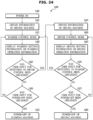
- FIG. 24 is a view illustrating a power-off method of a washing machine and a drying machine according to an embodiment.
- FIG. 25 is a view illustrating power-off of a drying machine by a washing machine according to an embodiment.
- the washing machine 100 may be turned on (1405), obtain information of the drying machine 300 from the drying machine 300 (1410), operate in the washer control mode (1415), display the washing setting information or the washing operation information (1420), and determine whether the user input for switching to the dryer control mode is obtained (1425).
- Operation 1405, operation 1410, operation 1415, operation 1420, and operation 1425 may be the same as operation 1105, operation 1110, operation 1115, operation 1120, and operation 1125 illustrated in FIG. 16 .
- the washing machine 100 may determine whether the user input for power-off in the washer control mode (user input for switching to the standby state) is obtained (1430).
- the user may input the user input for switching the washing machine 100 in the "on state” to the "standby state” through the washer power button 211 in the washer control mode.
- the controller 190 may switch the washing machine 100 from the "standby state” to the “on state” or from the "on state” to the 'standby state.
- the washing machine 100 may wait for the user input in the washer control mode.
- the washing machine 100 is powered-off (turns washing machine to the standby state) (1435).
- the controller 190 may switch the washing machine 100 in the "on state” to the 'standby state.
- the power may be supplied to all of the components of the washing machine 100 in the "on state," but in the 'standby state,' the power may be limitedly supplied to the control panel 110, the communication device 180, and the controller 190.
- the controller 190 may switch the washing machine 100 in the "on state” to the "standby state” in response to obtaining the user input for power-off in the washer control mode.
- the washing machine 100 may obtain information of the drying machine 300 from the drying machine 300 (1455).
- the washing machine 100 may operate in the dryer control mode (1460), display the drying setting information or the drying operation information (1465), and determine whether the user input for switching to the washer control mode is obtained (1470).
- Operation 1455, operation 1460, operation 1465, and operation 1470 may be the same as operation 1155, operation 1160, operation 1165, and operation 1170 illustrated in FIG. 16 .
- the washing machine 100 may operate in the washer control mode (1415).
- the washing machine 100 may determine whether the user input for power-off in the dryer control mode is obtained (1475). When it is determined that the washing machine 100 has obtained the user input for power-off (YES in 1475), the drying machine 300 may be powered-off (turned the washing machine to the standby state) (1480).
- the controller 190 may transmit the control command for switching the power state of the drying machine 300 to the drying machine 300 through the communication device 180.
- the controller 190 may identify the power state of the drying machine 300 (e.g., in the standby state or in the on state) based on information received from the drying machine 300. Upon identifying that the drying machine 300 is in the 'standby state,' the controller 190 may transmit the control command for switching the drying machine 300 that is in the "standby state” to the "on state” to the drying machine 300. Upon identifying that the drying machine 300 is in the "on state,” the controller 190 may transmit the control command for switching the drying machine 300 that is in the "on state” to the "standby state” to the drying machine 300.
- the controller 390 of the drying machine 300 may receive the control command for switching the power state from the washing machine 100 and switch the power state of the drying machine 300 in response to the received control command.
- the washing machine 100 changes the power state of the drying machine 300 in response to the washer power button 211 being touched or pressed in the dryer control mode, but is not limited thereto.
- the washing machine 100 may change the power state of the washing machine 100 itself in response to the washer power button 211 being touched or pressed in the dryer control mode.
- the washing machine 100 may be switched from the "on state” to the "standby state” in response to the washer power button 211 being touched or pressed in the dryer control mode.
- the control panel may include a first control switch and a second control switch.
- the controller may switch to the first mode in response to the user input through the first control switch in the second mode, and may switch to the second mode in response to the user input through the second control switch in the first mode.
- embodiments can thus be implemented through computer readable code/instructions in/on a medium, e.g., a computer readable medium, to control at least one processing element to implement any above described exemplary embodiment.
- a medium e.g., a computer readable medium
- the medium can correspond to any medium/media permitting the storing and/or transmission of the computer readable code.
Landscapes
- Engineering & Computer Science (AREA)
- Textile Engineering (AREA)
- Computer Networks & Wireless Communication (AREA)
- Control Of Washing Machine And Dryer (AREA)
Claims (12)
- Waschmaschine (100), umfassend:ein Steuerfeld (110);eine Kommunikationsvorrichtung (180), die zum Kommunizieren mit einer Trocknungsmaschine (300) konfiguriert ist; undeine Steuerung (190), die mit dem Steuerfeld (110) und der Kommunikationsvorrichtung (180) verbunden ist,dadurch gekennzeichnet, dassdas Steuerfeld (110) einen Gangwahldrehschalter (241), eine Ganganzeige (251) und eine Trocknersteuerungstaste (221) umfasst, die konfiguriert ist, um eine Benutzereingabe zum Umschalten von einem Waschmaschinensteuerungsmodus zum Steuern eines Waschvorgangs und/oder einer Wascheinstellung der Waschmaschine (100) zu einem Trocknersteuerungsmodus zum Steuern eines Trocknungsvorgangs und/oder einer Trocknungeinstellung der Trocknungsmaschine (300) zu erhalten,wobei die Steuerung (190) konfiguriert ist zum:Anzeigen (1140), auf der Ganganzeige (251), einer Vielzahl von Waschgängen in einer Reihenfolge gemäß einer Drehung des Gangwahldrehschalters (241) zum Auswählen eines Waschgangs im Waschmaschinensteuerungsmodus,als Reaktion auf das Erhalten (1125) der Benutzereingabe über die Trocknersteuerungstaste (221) Umschalten vom Waschmaschinensteuerungsmodus zum Trocknersteuerungsmodus,Anzeigen (1185) einer Vielzahl von Trocknungsgängen auf der Ganganzeige (251) in einer Reihenfolge gemäß der Drehung des Gangwahldrehschalters (241) zur Auswahl eines Trocknungsgangs im Trocknersteuerungsmodus, undÜbertragen (1190) von Informationen, die dem ausgewählten Trocknungsgang entsprechen, der auf der Ganganzeige (251) im Trocknersteuerungsmodus angezeigt wird, an die Trocknungsmaschine (300) über die Kommunikationsvorrichtung (180) zum Steuern eines Trocknungsvorgangs der Trocknungsmaschine (300).
- Waschmaschine nach Anspruch 1, wobeidas Steuerfeld (110) ferner eine Trocknungsvorgangstaste (231) umfasst, die konfiguriert ist, um eine Benutzereingabe zum Starten eines Vorgangs der Trocknungsmaschine (300) zu erhalten, undwobei die Steuerung (190) ferner konfiguriert ist, um einen Steuerbefehl zum Starten des Trocknungsvorgangs an die Trocknungsmaschine (300) über die Kommunikationsvorrichtung (180) als Reaktion auf das Erhalten der Benutzereingabe über die Trocknungsvorgangstaste (231)zu übertragen.
- Waschmaschine nach Anspruch 1, wobei die Steuerung (190) ferner konfiguriert ist, um die Waschmaschine (100) als Reaktion auf das Erhalten einer Benutzereingabe über eine Waschmaschineneinschalttaste (211) im Trocknersteuerungsmodus auszuschalten.
- Waschmaschine nach Anspruch 1, wobei die Steuerung (190) ferner konfiguriert ist zum:als Reaktion auf das Erhalten einer Benutzereingabe über die Trocknersteuerungstaste (221) Identifizieren, ob die Waschmaschine (100) mit der Trocknungsmaschine (300) verbunden ist, undAnzeigen des Trocknungsgangs auf der Ganganzeige (251) basierend auf einer Verbindung der Waschmaschine (100) mit der Trocknungsmaschine (300).
- Waschmaschine nach Anspruch 4, wobei die Steuerung (190) ferner so konfiguriert ist, dass sie als Reaktion auf das Erhalten einer Benutzereingabe zum Umschalten auf den Waschmaschinen-Steuerungsmodus über das Steuerfeld (110) einen Waschgang auf der Ganganzeige (251) anzeigt, während der Trocknungsgang auf der Ganganzeige (251) angezeigt wird.
- Waschmaschine nach Anspruch 1, wobei das Steuerfeld (110) ferner eine Fernsteuerungstaste (281) und eine Einstellungsanzeige (291) umfasst, und
wobei die Steuerung (190) ferner konfiguriert ist, um auf der Einstellungsanzeige (291) anzuzeigen, ob eine Fernsteuerung der Waschmaschine (100) als Reaktion auf eine Benutzereingabe über die Fernsteuerungstaste (281)aktiviert ist. - Verfahren zum Steuern einer Waschmaschine, wobei die Waschmaschine (100) ein Steuerfeld (110), das einen Gangwahldrehschalter (241), eine Ganganzeige (251), eine Trocknersteuerungstaste (221), die konfiguriert ist, um eine Benutzereingabe zum Umschalten von einem Waschmaschinensteuerungsmodus zum Steuern des Waschvorgangs und/oder der Wascheinstellung der Waschmaschine (100) zu einem Trocknersteuerungsmodus zum Steuern eines Trocknungsvorgangs und/oder einer Trocknungseinstellung einer Trocknungsmaschine (300) zu erhalten, eine Kommunikationsvorrichtung (180) und eine Steuerung (190) umfasst, wobei das Verfahren umfasst:Anzeigen (1140) einer Vielzahl von Waschgängen auf der Ganganzeige in einer Reihenfolge gemäß einer Drehung des Gangwahldrehschalters zum Auswählen eines Waschgangs in einem Waschmaschinensteuerungsmodus;als Reaktion auf das Erhalten (1125) einer Benutzereingabe über die Trocknersteuerungstaste, Umschalten vom Waschmaschinensteuerungsmodus zum Trocknersteuerungsmodus,Anzeigen (1185) einer Vielzahl von Trocknungsgängen auf der Ganganzeige in einer Reihenfolge gemäß der Drehung des Gangwahldrehschalters zur Auswahl eines Trocknungsgangs im Trocknersteuerungsmodus,Übertragen (1190) von Informationen, die dem ausgewählten Trocknungsgang entsprechen, der auf der Ganganzeige im Trocknersteuerungsmodus angezeigt wird, an die Trocknungsmaschine über die Kommunikationsvorrichtung zum Steuern eines Trocknungsvorgangs der Trocknungsmaschine.
- Verfahren nach Anspruch 7, wobeidas Steuerfeld (110) ferner eine Trocknungsvorgangstaste umfasst, unddas Verfahren ferner Folgendes umfasst:Erhalten (1230) einer Benutzereingabe zum Starten eines Vorgangs der Trocknungsmaschine über die Trocknungsvorgangstaste, undÜbertragen (1235), unter Verwendung der Steuerung, eines Steuerbefehls zum Starten des Trocknungsvorgangs an die Trocknungsmaschine über die Kommunikationsvorrichtung als Reaktion auf das Erhalten der Benutzereingabe über die Vorgangstaste.
- Verfahren nach Anspruch 7, ferner umfassend:
Ausschalten der Waschmaschine mittels der Steuerung als Reaktion auf eine Benutzereingabe über eine Waschmaschineneinschalttaste im Trocknersteuerungsmodus. - Verfahren nach Anspruch 7, ferner umfassend:als Reaktion auf das Erhalten (1040) einer Benutzereingabe über die Trocknersteuerungstaste, Identifizieren (1045), ob die Waschmaschine mit der Trocknungsmaschine verbunden ist, undAnzeigen (1070, 1075) des Trocknungsgangs auf der Ganganzeige basierend auf einer Verbindung der Waschmaschine mit der Trocknungsmaschine.
- Verfahren nach Anspruch 10, ferner umfassend:
Anzeigen (1030, 1035) eines Waschgangs auf der Ganganzeige als Reaktion auf das Erhalten (1080) einer Benutzereingabe zum Umschalten auf den Waschmaschinen-Steuerungsmodus über das Steuerfeld, während der Trocknungsgang auf der Ganganzeige angezeigt wird. - Verfahren nach Anspruch 7, wobeidas Steuerfeld (110), ferner eine Fernsteuerungstaste und eine Einstellungsanzeige umfasst, unddas Verfahren ferner Folgendes umfasst:
Anzeigen auf der Einstellungsanzeige, ob eine Fernsteuerung der Waschmaschine als Reaktion auf eine Benutzereingabe über die Fernsteuerungstaste aktiviert ist.
Priority Applications (1)
| Application Number | Priority Date | Filing Date | Title |
|---|---|---|---|
| EP25179033.3A EP4585739A3 (de) | 2020-01-03 | 2020-11-11 | Wäscheverarbeitungsvorrichtung und verfahren zur steuerung davon |
Applications Claiming Priority (4)
| Application Number | Priority Date | Filing Date | Title |
|---|---|---|---|
| KR1020200000888A KR102911193B1 (ko) | 2020-01-03 | 2020-01-03 | 세탁기, 그 제어 방법 및 그의 컨트롤 패널 |
| KR1020200067048A KR102236743B1 (ko) | 2020-01-03 | 2020-06-03 | 의류 처리 장치 및 그 제어 방법 |
| EP20897621.7A EP3882389B1 (de) | 2020-01-03 | 2020-11-11 | Kleidungsverarbeitungsvorrichtung und steuerungsverfahren dafür |
| PCT/KR2020/015767 WO2021137417A1 (ko) | 2020-01-03 | 2020-11-11 | 의류 처리 장치 및 그 제어 방법 |
Related Parent Applications (2)
| Application Number | Title | Priority Date | Filing Date |
|---|---|---|---|
| EP20897621.7A Division EP3882389B1 (de) | 2020-01-03 | 2020-11-11 | Kleidungsverarbeitungsvorrichtung und steuerungsverfahren dafür |
| EP20897621.7A Division-Into EP3882389B1 (de) | 2020-01-03 | 2020-11-11 | Kleidungsverarbeitungsvorrichtung und steuerungsverfahren dafür |
Related Child Applications (2)
| Application Number | Title | Priority Date | Filing Date |
|---|---|---|---|
| EP25179033.3A Division-Into EP4585739A3 (de) | 2020-01-03 | 2020-11-11 | Wäscheverarbeitungsvorrichtung und verfahren zur steuerung davon |
| EP25179033.3A Division EP4585739A3 (de) | 2020-01-03 | 2020-11-11 | Wäscheverarbeitungsvorrichtung und verfahren zur steuerung davon |
Publications (4)
| Publication Number | Publication Date |
|---|---|
| EP4296419A2 EP4296419A2 (de) | 2023-12-27 |
| EP4296419A3 EP4296419A3 (de) | 2024-04-03 |
| EP4296419B1 true EP4296419B1 (de) | 2025-07-02 |
| EP4296419C0 EP4296419C0 (de) | 2025-07-02 |
Family
ID=76655096
Family Applications (3)
| Application Number | Title | Priority Date | Filing Date |
|---|---|---|---|
| EP25179033.3A Pending EP4585739A3 (de) | 2020-01-03 | 2020-11-11 | Wäscheverarbeitungsvorrichtung und verfahren zur steuerung davon |
| EP23209148.8A Active EP4296419B1 (de) | 2020-01-03 | 2020-11-11 | Wäscheverarbeitungsvorrichtung und verfahren zur steuerung davon |
| EP20897621.7A Active EP3882389B1 (de) | 2020-01-03 | 2020-11-11 | Kleidungsverarbeitungsvorrichtung und steuerungsverfahren dafür |
Family Applications Before (1)
| Application Number | Title | Priority Date | Filing Date |
|---|---|---|---|
| EP25179033.3A Pending EP4585739A3 (de) | 2020-01-03 | 2020-11-11 | Wäscheverarbeitungsvorrichtung und verfahren zur steuerung davon |
Family Applications After (1)
| Application Number | Title | Priority Date | Filing Date |
|---|---|---|---|
| EP20897621.7A Active EP3882389B1 (de) | 2020-01-03 | 2020-11-11 | Kleidungsverarbeitungsvorrichtung und steuerungsverfahren dafür |
Country Status (5)
| Country | Link |
|---|---|
| US (5) | US11421367B2 (de) |
| EP (3) | EP4585739A3 (de) |
| KR (1) | KR102236743B1 (de) |
| DE (1) | DE212020000499U1 (de) |
| WO (1) | WO2021137417A1 (de) |
Families Citing this family (14)
| Publication number | Priority date | Publication date | Assignee | Title |
|---|---|---|---|---|
| USD937516S1 (en) * | 2019-03-11 | 2021-11-30 | Samsung Electronics Co., Ltd. | Washing machine |
| USD937515S1 (en) * | 2019-03-11 | 2021-11-30 | Samsung Electronics Co., Ltd. | Washing machine |
| WO2022014890A1 (ko) | 2020-07-17 | 2022-01-20 | 삼성전자주식회사 | 세탁기 및 그 제어 방법 |
| KR102757406B1 (ko) * | 2021-06-28 | 2025-01-21 | 엘지전자 주식회사 | 의류처리장치 및 상기 의류처리장치를 구비하는 시스템 |
| KR102757410B1 (ko) | 2021-06-28 | 2025-01-21 | 엘지전자 주식회사 | 의류처리장치 및 상기 의류처리장치를 구비하는 시스템 |
| KR20230004177A (ko) * | 2021-06-30 | 2023-01-06 | 엘지전자 주식회사 | 인터페이스 및 인터페이스가 구비된 의류처리장치 |
| KR20230105857A (ko) * | 2022-01-05 | 2023-07-12 | 엘지전자 주식회사 | 의류처리장치 |
| KR102886161B1 (ko) * | 2022-01-05 | 2025-11-14 | 엘지전자 주식회사 | 의류처리장치 |
| WO2023182629A1 (ko) * | 2022-03-25 | 2023-09-28 | 삼성전자 주식회사 | 건조기를 제어하기 위한 세탁기 및 세탁기의 건조기 제어 방법 |
| KR102883455B1 (ko) * | 2022-06-16 | 2025-11-06 | 엘지전자 주식회사 | 의류처리장치 |
| US20240337057A1 (en) * | 2023-04-06 | 2024-10-10 | Haier Us Appliance Solutions, Inc. | Optimized drying cycle based on washing cycle |
| KR102920497B1 (ko) * | 2023-07-27 | 2026-02-03 | 엘지전자 주식회사 | 의류처리장치 및 의류처리장치의 제어방법 |
| KR102944687B1 (ko) | 2023-07-27 | 2026-03-27 | 엘지전자 주식회사 | 의류처리장치 및 의류처리장치의 제어방법 |
| CN119859898B (zh) * | 2023-10-20 | 2025-11-25 | 海信冰箱有限公司 | 控制洗衣机和干衣机的方法、干衣机和洗衣机的组合装置 |
Family Cites Families (23)
| Publication number | Priority date | Publication date | Assignee | Title |
|---|---|---|---|---|
| KR970051867U (ko) | 1996-02-07 | 1997-09-08 | 세탁기 및 의류건조기의 복합제어장치 | |
| US7096601B2 (en) | 2003-12-26 | 2006-08-29 | Lg Electronics Inc. | Apparatus and method for controlling washing/drying system |
| KR100607278B1 (ko) | 2003-12-26 | 2006-07-28 | 엘지전자 주식회사 | 건조기의 제어 시스템 및 제어 방법 |
| KR100607273B1 (ko) | 2003-12-26 | 2006-07-28 | 엘지전자 주식회사 | 세탁기와 건조기 스텍구조의 조작장치 |
| KR100717458B1 (ko) | 2003-12-26 | 2007-05-14 | 엘지전자 주식회사 | 세탁기 건조기 스텍구조의 조작장치 및 조작방법 |
| KR100607280B1 (ko) | 2003-12-26 | 2006-07-28 | 엘지전자 주식회사 | 세탁기 건조기 스텍구조의 조작장치 및 조작방법 |
| KR100607279B1 (ko) | 2003-12-26 | 2006-07-28 | 엘지전자 주식회사 | 세탁기 건조기 스텍구조의 조작장치 |
| KR20070067977A (ko) | 2005-12-26 | 2007-06-29 | 엘지전자 주식회사 | 세탁 또는 세탁물 건조를 위한 기계장치 및 이를 포함한복합세탁장치 |
| CN101168901A (zh) | 2006-10-23 | 2008-04-30 | 南京乐金熊猫电器有限公司 | 具有无线通信控制器的洗衣机或洗涤物干燥装置 |
| KR20090131826A (ko) * | 2008-06-19 | 2009-12-30 | 엘지전자 주식회사 | 세탁장치의 입력장치 |
| KR20110110660A (ko) * | 2010-04-01 | 2011-10-07 | 엘지전자 주식회사 | 스택 구조를 갖는 의류처리장치 |
| KR20140032262A (ko) | 2012-09-06 | 2014-03-14 | 엘지전자 주식회사 | 가전제품 및 이를 포함하여 이루어지는 온라인 시스템 |
| CN106032625B (zh) | 2015-03-11 | 2019-12-13 | 青岛海尔滚筒洗衣机有限公司 | 一种洗衣机和洗衣机的控制方法 |
| CN106480659B (zh) | 2015-08-26 | 2020-05-08 | 青岛海尔滚筒洗衣机有限公司 | 一种洗衣机及其控制方法 |
| CN106948124A (zh) * | 2016-01-06 | 2017-07-14 | 青岛海尔洗衣机有限公司 | 多滚筒洗衣机及其控制方法 |
| AU2017204095B2 (en) | 2017-01-13 | 2019-08-08 | Lg Electronics Inc. | Laundry treating apparatus and method of the same |
| CN108570795B (zh) * | 2017-03-07 | 2021-01-22 | 重庆海尔滚筒洗衣机有限公司 | 一种洗衣机的远程控制方法 |
| CN108729111B (zh) * | 2017-04-24 | 2020-08-04 | 青岛海尔滚筒洗衣机有限公司 | 一种洗衣机控制方法及洗衣机 |
| US11473230B2 (en) * | 2017-07-17 | 2022-10-18 | Whirlpool Corporation | Selectable method of control for double basket laundry treating appliance |
| CN109518411B (zh) * | 2017-09-18 | 2021-10-26 | 青岛海尔洗涤电器有限公司 | 一种衣物处理设备及其控制方法 |
| US10745841B2 (en) * | 2018-07-17 | 2020-08-18 | Haier Us Appliance Solutions, Inc. | Systems and methods for controlling an appliance using another appliance communicatively coupled thereto |
| KR101999701B1 (ko) * | 2018-07-18 | 2019-07-12 | 엘지전자 주식회사 | 의류처리장치 및 그 제어방법 |
| KR102747291B1 (ko) * | 2019-07-17 | 2024-12-31 | 엘지전자 주식회사 | 원격 제어 가능한 세탁물 처리기기 및 이의 제어 방법 |
-
2020
- 2020-06-03 KR KR1020200067048A patent/KR102236743B1/ko active Active
- 2020-11-02 US US17/087,344 patent/US11421367B2/en active Active
- 2020-11-11 WO PCT/KR2020/015767 patent/WO2021137417A1/ko not_active Ceased
- 2020-11-11 EP EP25179033.3A patent/EP4585739A3/de active Pending
- 2020-11-11 DE DE212020000499.4U patent/DE212020000499U1/de active Active
- 2020-11-11 EP EP23209148.8A patent/EP4296419B1/de active Active
- 2020-11-11 EP EP20897621.7A patent/EP3882389B1/de active Active
-
2022
- 2022-07-13 US US17/812,347 patent/US11828015B2/en active Active
-
2023
- 2023-03-24 US US18/189,961 patent/US12522964B2/en active Active
- 2023-12-15 US US18/542,534 patent/US20240117552A1/en active Pending
- 2023-12-15 US US18/542,528 patent/US20240117551A1/en active Pending
Also Published As
| Publication number | Publication date |
|---|---|
| US20240117551A1 (en) | 2024-04-11 |
| EP4296419A3 (de) | 2024-04-03 |
| US11828015B2 (en) | 2023-11-28 |
| KR102236743B1 (ko) | 2021-04-06 |
| US20210207309A1 (en) | 2021-07-08 |
| US20220349107A1 (en) | 2022-11-03 |
| US20230235496A1 (en) | 2023-07-27 |
| EP3882389B1 (de) | 2023-12-27 |
| US20240117552A1 (en) | 2024-04-11 |
| WO2021137417A1 (ko) | 2021-07-08 |
| EP3882389A4 (de) | 2022-02-16 |
| EP4585739A3 (de) | 2025-09-03 |
| EP3882389A1 (de) | 2021-09-22 |
| EP3882389C0 (de) | 2023-12-27 |
| EP4296419C0 (de) | 2025-07-02 |
| DE212020000499U1 (de) | 2021-08-26 |
| EP4585739A2 (de) | 2025-07-16 |
| US11421367B2 (en) | 2022-08-23 |
| US12522964B2 (en) | 2026-01-13 |
| EP4296419A2 (de) | 2023-12-27 |
| KR102236743B9 (ko) | 2021-10-15 |
Similar Documents
| Publication | Publication Date | Title |
|---|---|---|
| EP4296419B1 (de) | Wäscheverarbeitungsvorrichtung und verfahren zur steuerung davon | |
| EP4085167B1 (de) | Waschmaschine und steuerverfahren dafür und bedienfeld derselben | |
| KR102861544B1 (ko) | 의류 처리 장치 및 그 제어 방법 | |
| US11198964B2 (en) | Laundry treating apparatus and method of the same | |
| US11377780B2 (en) | Method to control operation of a laundry dryer | |
| CN105473779A (zh) | 具有增强的操作灵活性的衣物烘干器具 | |
| KR20140103763A (ko) | 세탁기 및 그 제어방법 | |
| JP2012070956A (ja) | 衣類乾燥機 | |
| AU2022302747B2 (en) | Laundry treating apparatus and system having the same | |
| US20240301605A1 (en) | Laundry treating apparatus and system having the same | |
| KR20250042031A (ko) | 의류처리시스템 및 그 제어 방법 | |
| KR20070015685A (ko) | 세탁기와 건조기 간 통신 제어장치 | |
| KR20250162283A (ko) | 의류처리장치 및 그 제어방법 | |
| KR20240076647A (ko) | 의류처리장치 및 의류처리시스템 | |
| KR20240076648A (ko) | 의류처리시스템 | |
| KR20250030887A (ko) | 세탁 및 건조 방법을 가이드하는 방법 및 그에 따른 세탁기 | |
| KR20240076649A (ko) | 의류처리시스템 및 의류처리시스템의 진단방법 | |
| KR20250032798A (ko) | 의류처리장치 및 그 제어 방법 | |
| KR20250106657A (ko) | 의류처리장치 및 그 제어 방법 |
Legal Events
| Date | Code | Title | Description |
|---|---|---|---|
| PUAI | Public reference made under article 153(3) epc to a published international application that has entered the european phase |
Free format text: ORIGINAL CODE: 0009012 |
|
| STAA | Information on the status of an ep patent application or granted ep patent |
Free format text: STATUS: THE APPLICATION HAS BEEN PUBLISHED |
|
| AC | Divisional application: reference to earlier application |
Ref document number: 3882389 Country of ref document: EP Kind code of ref document: P |
|
| AK | Designated contracting states |
Kind code of ref document: A2 Designated state(s): AL AT BE BG CH CY CZ DE DK EE ES FI FR GB GR HR HU IE IS IT LI LT LU LV MC MK MT NL NO PL PT RO RS SE SI SK SM TR |
|
| REG | Reference to a national code |
Ref country code: DE Free format text: PREVIOUS MAIN CLASS: D06F0029000000 Ref country code: DE Ref legal event code: R079 Ref document number: 602020054066 Country of ref document: DE Free format text: PREVIOUS MAIN CLASS: D06F0029000000 Ipc: D06F0034050000 |
|
| PUAL | Search report despatched |
Free format text: ORIGINAL CODE: 0009013 |
|
| AK | Designated contracting states |
Kind code of ref document: A3 Designated state(s): AL AT BE BG CH CY CZ DE DK EE ES FI FR GB GR HR HU IE IS IT LI LT LU LV MC MK MT NL NO PL PT RO RS SE SI SK SM TR |
|
| RIC1 | Information provided on ipc code assigned before grant |
Ipc: D06F 105/58 20200101ALN20240227BHEP Ipc: D06F 105/50 20200101ALN20240227BHEP Ipc: D06F 103/40 20200101ALN20240227BHEP Ipc: D06F 101/20 20200101ALN20240227BHEP Ipc: D06F 29/00 20060101ALI20240227BHEP Ipc: D06F 58/34 20200101ALI20240227BHEP Ipc: D06F 33/50 20200101ALI20240227BHEP Ipc: D06F 33/30 20200101ALI20240227BHEP Ipc: D06F 34/20 20200101ALI20240227BHEP Ipc: D06F 34/28 20200101ALI20240227BHEP Ipc: D06F 34/05 20200101AFI20240227BHEP |
|
| STAA | Information on the status of an ep patent application or granted ep patent |
Free format text: STATUS: REQUEST FOR EXAMINATION WAS MADE |
|
| 17P | Request for examination filed |
Effective date: 20240704 |
|
| RBV | Designated contracting states (corrected) |
Designated state(s): AL AT BE BG CH CY CZ DE DK EE ES FI FR GB GR HR HU IE IS IT LI LT LU LV MC MK MT NL NO PL PT RO RS SE SI SK SM TR |
|
| GRAP | Despatch of communication of intention to grant a patent |
Free format text: ORIGINAL CODE: EPIDOSNIGR1 |
|
| STAA | Information on the status of an ep patent application or granted ep patent |
Free format text: STATUS: GRANT OF PATENT IS INTENDED |
|
| RIC1 | Information provided on ipc code assigned before grant |
Ipc: D06F 105/58 20200101ALN20250109BHEP Ipc: D06F 105/50 20200101ALN20250109BHEP Ipc: D06F 103/40 20200101ALN20250109BHEP Ipc: D06F 101/20 20200101ALN20250109BHEP Ipc: D06F 29/00 20060101ALI20250109BHEP Ipc: D06F 58/34 20200101ALI20250109BHEP Ipc: D06F 33/50 20200101ALI20250109BHEP Ipc: D06F 33/30 20200101ALI20250109BHEP Ipc: D06F 34/20 20200101ALI20250109BHEP Ipc: D06F 34/28 20200101ALI20250109BHEP Ipc: D06F 34/05 20200101AFI20250109BHEP |
|
| RIC1 | Information provided on ipc code assigned before grant |
Ipc: D06F 105/58 20200101ALN20250113BHEP Ipc: D06F 105/50 20200101ALN20250113BHEP Ipc: D06F 103/40 20200101ALN20250113BHEP Ipc: D06F 101/20 20200101ALN20250113BHEP Ipc: D06F 29/00 20060101ALI20250113BHEP Ipc: D06F 58/34 20200101ALI20250113BHEP Ipc: D06F 33/50 20200101ALI20250113BHEP Ipc: D06F 33/30 20200101ALI20250113BHEP Ipc: D06F 34/20 20200101ALI20250113BHEP Ipc: D06F 34/28 20200101ALI20250113BHEP Ipc: D06F 34/05 20200101AFI20250113BHEP |
|
| INTG | Intention to grant announced |
Effective date: 20250128 |
|
| GRAS | Grant fee paid |
Free format text: ORIGINAL CODE: EPIDOSNIGR3 |
|
| GRAA | (expected) grant |
Free format text: ORIGINAL CODE: 0009210 |
|
| STAA | Information on the status of an ep patent application or granted ep patent |
Free format text: STATUS: THE PATENT HAS BEEN GRANTED |
|
| AC | Divisional application: reference to earlier application |
Ref document number: 3882389 Country of ref document: EP Kind code of ref document: P |
|
| AK | Designated contracting states |
Kind code of ref document: B1 Designated state(s): AL AT BE BG CH CY CZ DE DK EE ES FI FR GB GR HR HU IE IS IT LI LT LU LV MC MK MT NL NO PL PT RO RS SE SI SK SM TR |
|
| REG | Reference to a national code |
Ref country code: GB Ref legal event code: FG4D |
|
| REG | Reference to a national code |
Ref country code: CH Ref legal event code: EP |
|
| REG | Reference to a national code |
Ref country code: DE Ref legal event code: R096 Ref document number: 602020054066 Country of ref document: DE |
|
| REG | Reference to a national code |
Ref country code: IE Ref legal event code: FG4D |
|
| U01 | Request for unitary effect filed |
Effective date: 20250716 |
|
| U07 | Unitary effect registered |
Designated state(s): AT BE BG DE DK EE FI FR IT LT LU LV MT NL PT RO SE SI Effective date: 20250723 |
|
| U20 | Renewal fee for the european patent with unitary effect paid |
Year of fee payment: 6 Effective date: 20251124 |
|
| PG25 | Lapsed in a contracting state [announced via postgrant information from national office to epo] |
Ref country code: IS Free format text: LAPSE BECAUSE OF FAILURE TO SUBMIT A TRANSLATION OF THE DESCRIPTION OR TO PAY THE FEE WITHIN THE PRESCRIBED TIME-LIMIT Effective date: 20251102 |
|
| PGFP | Annual fee paid to national office [announced via postgrant information from national office to epo] |
Ref country code: GB Payment date: 20251001 Year of fee payment: 6 |
|
| PG25 | Lapsed in a contracting state [announced via postgrant information from national office to epo] |
Ref country code: NO Free format text: LAPSE BECAUSE OF FAILURE TO SUBMIT A TRANSLATION OF THE DESCRIPTION OR TO PAY THE FEE WITHIN THE PRESCRIBED TIME-LIMIT Effective date: 20251002 |
|
| PG25 | Lapsed in a contracting state [announced via postgrant information from national office to epo] |
Ref country code: HR Free format text: LAPSE BECAUSE OF FAILURE TO SUBMIT A TRANSLATION OF THE DESCRIPTION OR TO PAY THE FEE WITHIN THE PRESCRIBED TIME-LIMIT Effective date: 20250702 |
|
| PG25 | Lapsed in a contracting state [announced via postgrant information from national office to epo] |
Ref country code: GR Free format text: LAPSE BECAUSE OF FAILURE TO SUBMIT A TRANSLATION OF THE DESCRIPTION OR TO PAY THE FEE WITHIN THE PRESCRIBED TIME-LIMIT Effective date: 20251003 |
|
| PG25 | Lapsed in a contracting state [announced via postgrant information from national office to epo] |
Ref country code: CZ Free format text: LAPSE BECAUSE OF FAILURE TO SUBMIT A TRANSLATION OF THE DESCRIPTION OR TO PAY THE FEE WITHIN THE PRESCRIBED TIME-LIMIT Effective date: 20250702 |
|
| PG25 | Lapsed in a contracting state [announced via postgrant information from national office to epo] |
Ref country code: PL Free format text: LAPSE BECAUSE OF FAILURE TO SUBMIT A TRANSLATION OF THE DESCRIPTION OR TO PAY THE FEE WITHIN THE PRESCRIBED TIME-LIMIT Effective date: 20250702 |
|
| PG25 | Lapsed in a contracting state [announced via postgrant information from national office to epo] |
Ref country code: RS Free format text: LAPSE BECAUSE OF FAILURE TO SUBMIT A TRANSLATION OF THE DESCRIPTION OR TO PAY THE FEE WITHIN THE PRESCRIBED TIME-LIMIT Effective date: 20251002 |
|
| PG25 | Lapsed in a contracting state [announced via postgrant information from national office to epo] |
Ref country code: ES Free format text: LAPSE BECAUSE OF FAILURE TO SUBMIT A TRANSLATION OF THE DESCRIPTION OR TO PAY THE FEE WITHIN THE PRESCRIBED TIME-LIMIT Effective date: 20250702 |
|
| PG25 | Lapsed in a contracting state [announced via postgrant information from national office to epo] |
Ref country code: SM Free format text: LAPSE BECAUSE OF FAILURE TO SUBMIT A TRANSLATION OF THE DESCRIPTION OR TO PAY THE FEE WITHIN THE PRESCRIBED TIME-LIMIT Effective date: 20250702 |
|
| PG25 | Lapsed in a contracting state [announced via postgrant information from national office to epo] |
Ref country code: SK Free format text: LAPSE BECAUSE OF FAILURE TO SUBMIT A TRANSLATION OF THE DESCRIPTION OR TO PAY THE FEE WITHIN THE PRESCRIBED TIME-LIMIT Effective date: 20250702 |