EP4296553A1 - Kühlelement für eine elektrische komponente, insbesondere für eine elektrische batterie eines elektro- oder hybridfahrzeugs - Google Patents
Kühlelement für eine elektrische komponente, insbesondere für eine elektrische batterie eines elektro- oder hybridfahrzeugs Download PDFInfo
- Publication number
- EP4296553A1 EP4296553A1 EP23180234.9A EP23180234A EP4296553A1 EP 4296553 A1 EP4296553 A1 EP 4296553A1 EP 23180234 A EP23180234 A EP 23180234A EP 4296553 A1 EP4296553 A1 EP 4296553A1
- Authority
- EP
- European Patent Office
- Prior art keywords
- pipe
- connector
- electric
- aperture
- external connecting
- Prior art date
- Legal status (The legal status is an assumption and is not a legal conclusion. Google has not performed a legal analysis and makes no representation as to the accuracy of the status listed.)
- Pending
Links
Images

Classifications
-
- F—MECHANICAL ENGINEERING; LIGHTING; HEATING; WEAPONS; BLASTING
- F16—ENGINEERING ELEMENTS AND UNITS; GENERAL MEASURES FOR PRODUCING AND MAINTAINING EFFECTIVE FUNCTIONING OF MACHINES OR INSTALLATIONS; THERMAL INSULATION IN GENERAL
- F16L—PIPES; JOINTS OR FITTINGS FOR PIPES; SUPPORTS FOR PIPES, CABLES OR PROTECTIVE TUBING; MEANS FOR THERMAL INSULATION IN GENERAL
- F16L37/00—Couplings of the quick-acting type
- F16L37/008—Couplings of the quick-acting type for branching pipes; for joining pipes to walls
-
- F—MECHANICAL ENGINEERING; LIGHTING; HEATING; WEAPONS; BLASTING
- F16—ENGINEERING ELEMENTS AND UNITS; GENERAL MEASURES FOR PRODUCING AND MAINTAINING EFFECTIVE FUNCTIONING OF MACHINES OR INSTALLATIONS; THERMAL INSULATION IN GENERAL
- F16L—PIPES; JOINTS OR FITTINGS FOR PIPES; SUPPORTS FOR PIPES, CABLES OR PROTECTIVE TUBING; MEANS FOR THERMAL INSULATION IN GENERAL
- F16L37/00—Couplings of the quick-acting type
- F16L37/08—Couplings of the quick-acting type in which the connection between abutting or axially overlapping ends is maintained by locking members
- F16L37/084—Couplings of the quick-acting type in which the connection between abutting or axially overlapping ends is maintained by locking members combined with automatic locking
- F16L37/098—Couplings of the quick-acting type in which the connection between abutting or axially overlapping ends is maintained by locking members combined with automatic locking by means of flexible hooks
-
- F—MECHANICAL ENGINEERING; LIGHTING; HEATING; WEAPONS; BLASTING
- F16—ENGINEERING ELEMENTS AND UNITS; GENERAL MEASURES FOR PRODUCING AND MAINTAINING EFFECTIVE FUNCTIONING OF MACHINES OR INSTALLATIONS; THERMAL INSULATION IN GENERAL
- F16L—PIPES; JOINTS OR FITTINGS FOR PIPES; SUPPORTS FOR PIPES, CABLES OR PROTECTIVE TUBING; MEANS FOR THERMAL INSULATION IN GENERAL
- F16L41/00—Branching pipes; Joining pipes to walls
- F16L41/02—Branch units, e.g. made in one piece, welded, riveted
- F16L41/03—Branch units, e.g. made in one piece, welded, riveted comprising junction pieces for four or more pipe members
-
- H—ELECTRICITY
- H01—ELECTRIC ELEMENTS
- H01M—PROCESSES OR MEANS, e.g. BATTERIES, FOR THE DIRECT CONVERSION OF CHEMICAL ENERGY INTO ELECTRICAL ENERGY
- H01M10/00—Secondary cells; Manufacture thereof
- H01M10/60—Heating or cooling; Temperature control
- H01M10/61—Types of temperature control
- H01M10/613—Cooling or keeping cold
-
- H—ELECTRICITY
- H01—ELECTRIC ELEMENTS
- H01M—PROCESSES OR MEANS, e.g. BATTERIES, FOR THE DIRECT CONVERSION OF CHEMICAL ENERGY INTO ELECTRICAL ENERGY
- H01M10/00—Secondary cells; Manufacture thereof
- H01M10/60—Heating or cooling; Temperature control
- H01M10/62—Heating or cooling; Temperature control specially adapted for specific applications
- H01M10/625—Vehicles
-
- H—ELECTRICITY
- H01—ELECTRIC ELEMENTS
- H01M—PROCESSES OR MEANS, e.g. BATTERIES, FOR THE DIRECT CONVERSION OF CHEMICAL ENERGY INTO ELECTRICAL ENERGY
- H01M10/00—Secondary cells; Manufacture thereof
- H01M10/60—Heating or cooling; Temperature control
- H01M10/65—Means for temperature control structurally associated with the cells
- H01M10/655—Solid structures for heat exchange or heat conduction
- H01M10/6556—Solid parts with flow channel passages or pipes for heat exchange
-
- H—ELECTRICITY
- H01—ELECTRIC ELEMENTS
- H01M—PROCESSES OR MEANS, e.g. BATTERIES, FOR THE DIRECT CONVERSION OF CHEMICAL ENERGY INTO ELECTRICAL ENERGY
- H01M10/00—Secondary cells; Manufacture thereof
- H01M10/60—Heating or cooling; Temperature control
- H01M10/65—Means for temperature control structurally associated with the cells
- H01M10/656—Means for temperature control structurally associated with the cells characterised by the type of heat-exchange fluid
- H01M10/6567—Liquids
- H01M10/6568—Liquids characterised by flow circuits, e.g. loops, located externally to the cells or cell casings
-
- B—PERFORMING OPERATIONS; TRANSPORTING
- B60—VEHICLES IN GENERAL
- B60K—ARRANGEMENT OR MOUNTING OF PROPULSION UNITS OR OF TRANSMISSIONS IN VEHICLES; ARRANGEMENT OR MOUNTING OF PLURAL DIVERSE PRIME-MOVERS IN VEHICLES; AUXILIARY DRIVES FOR VEHICLES; INSTRUMENTATION OR DASHBOARDS FOR VEHICLES; ARRANGEMENTS IN CONNECTION WITH COOLING, AIR INTAKE, GAS EXHAUST OR FUEL SUPPLY OF PROPULSION UNITS IN VEHICLES
- B60K11/00—Arrangement in connection with cooling of propulsion units
- B60K11/02—Arrangement in connection with cooling of propulsion units with liquid cooling
-
- F—MECHANICAL ENGINEERING; LIGHTING; HEATING; WEAPONS; BLASTING
- F28—HEAT EXCHANGE IN GENERAL
- F28F—DETAILS OF HEAT-EXCHANGE AND HEAT-TRANSFER APPARATUS, OF GENERAL APPLICATION
- F28F9/00—Casings; Header boxes; Auxiliary supports for elements; Auxiliary members within casings
- F28F9/02—Header boxes; End plates
- F28F9/0243—Header boxes having a circular cross-section
-
- F—MECHANICAL ENGINEERING; LIGHTING; HEATING; WEAPONS; BLASTING
- F28—HEAT EXCHANGE IN GENERAL
- F28F—DETAILS OF HEAT-EXCHANGE AND HEAT-TRANSFER APPARATUS, OF GENERAL APPLICATION
- F28F9/00—Casings; Header boxes; Auxiliary supports for elements; Auxiliary members within casings
- F28F9/02—Header boxes; End plates
- F28F9/0246—Arrangements for connecting header boxes with flow lines
- F28F9/0256—Arrangements for coupling connectors with flow lines
- F28F9/0258—Arrangements for coupling connectors with flow lines of quick acting type, e.g. with snap action
-
- H—ELECTRICITY
- H01—ELECTRIC ELEMENTS
- H01M—PROCESSES OR MEANS, e.g. BATTERIES, FOR THE DIRECT CONVERSION OF CHEMICAL ENERGY INTO ELECTRICAL ENERGY
- H01M2220/00—Batteries for particular applications
- H01M2220/20—Batteries in motive systems, e.g. vehicle, ship, plane
-
- Y—GENERAL TAGGING OF NEW TECHNOLOGICAL DEVELOPMENTS; GENERAL TAGGING OF CROSS-SECTIONAL TECHNOLOGIES SPANNING OVER SEVERAL SECTIONS OF THE IPC; TECHNICAL SUBJECTS COVERED BY FORMER USPC CROSS-REFERENCE ART COLLECTIONS [XRACs] AND DIGESTS
- Y02—TECHNOLOGIES OR APPLICATIONS FOR MITIGATION OR ADAPTATION AGAINST CLIMATE CHANGE
- Y02E—REDUCTION OF GREENHOUSE GAS [GHG] EMISSIONS, RELATED TO ENERGY GENERATION, TRANSMISSION OR DISTRIBUTION
- Y02E60/00—Enabling technologies; Technologies with a potential or indirect contribution to GHG emissions mitigation
- Y02E60/10—Energy storage using batteries
Definitions
- the present invention relates to a cooling element for an electric component, in particular for an electric battery of an electric or hybrid vehicle.
- Some known cooling systems include a main pipe having a plurality of holes on its lateral surface, and respective secondary pipes are connected to such holes.
- the secondary pipes generally flexible, are fitted onto the main pipe and are held in position by elastic deformation and by respective corrugations to ensure fluid tightness.
- the cooling fluid flows through such pipes and reaches the component to be cooled.
- One problem of such systems is that they are expensive to manufacture e require much assembly time.
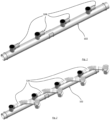
- Figs. 1 and 2 show a prior-art cooling system including a main pipe 102 having a plurality of holes 104. Respective secondary pipes 128 are connected to such holes 104. Secondary pipes 128, typically flexible, are fitted onto main pipe 102 and are held in position by elastic deformation and by respective corrugations to ensure fluid tightness. Holes 104 belong to tubular protrusions located on the lateral surface of main pipe 102. The cooling fluid flows through such pipes and reaches the component to be cooled. Secondary pipes 128 engage onto such tubular protrusions.
- One problem of such systems is that they are bulky and expensive to manufacture, and assembly is time-consuming.
- a cooling element 1 for an electric component in particular for an electric battery of an electric or hybrid vehicle, comprising:
- External connecting pipe 28 is connected to secondary aperture 4 through quick-coupling means.
- the at least one secondary aperture 4 is disposed on a lateral surface of pipe 2.
- the quick-coupling means are advantageous in that they allow for quick and easy installation of cooling element 1.
- such means make it possible to obtain a connection which does not take up much room.
- cooling element 1 is not expensive to manufacture.
- Rear end 10 and front end 16 are configured to be joined to a front end 16 and, respectively, a rear end 10 of another pipe 2, so as to fluidically connect such pipes 2 to each other.
- the at least one secondary aperture 4 faces towards the outer part of pipe 2.
- the coolant is intended to flow from pipe 2 (in particular, a delivery pipe) to external connecting pipe 28 and then reach an external cooling area where the electric component has to be cooled. Afterwards, the heated coolant flows back through another external connecting pipe 28 belonging to another pipe 2 (in particular, a return pipe).
- pipe 2 is made as one piece.
- pipe 2 is made from polymeric material, conveniently by means of an injection moulding process.
- pipe 2 is made of metal.
- the at least one external connecting pipe 28 is made from polymeric material, e.g. by means of an extrusion process.
- Element 1 is compact and versatile because it permits the circulation of a cooling fluid to and from an electric component whose dimensions do not interfere with the size of element 1.
- the coolant may be a liquid.
- This is particularly advantageous in an electric or hybrid vehicle, such as, for example, an electric car, having one or more big batteries, which can be effectively cooled while preserving the opportunity of positioning element 1 in the tight spaces of such a vehicle.
- a further advantage lies in the fact that, by combining a plurality of elements 1, it is possible to provide a modular cooling line that can be easily adapted to different electric components, e.g. different types of electric vehicles.
- the electric vehicle may be, for example, a fully electric vehicle or a hybrid vehicle. The user can assemble several elements 1 as required to create a modular assembly having a desired length.
- the illustrated element 1, in particular pipe 2 has an elongate, preferably straight, shape.
- Pipe 2 preferably has a circular cross-section.
- pipe 2 comprises a plurality of secondary apertures 4.
- element 1 is configured to be removably mounted to an adjacent cooling element 1.
- front end 16 and rear end 10 are configured to fit to respective rear ends 10 and, respectively, front ends 16 of other cooling elements 1.
- element 1 has flanges for establishing a connection between adjacent elements 1, e.g. by means of bolts.
- the ends are provided with seats for sealing means (e.g. a gasket) ensuring the necessary tightness of the connection between adjacent elements 1.
- element 1 is adapted to be welded to another element 1 for connecting such elements 1.
- This embodiment reduces the transverse size of element 1, because no flange is required.
- Another advantage of welding is the absence of screws or bolts, resulting in cost reduction.
- the weld is made between rear end 10 and front end 16 of adjacent elements 1.
- the element 1 has flanges configured to be welded to the flanges of adjacent elements 1.
- the process to be carried out for producing a cooling line comprising a plurality of modular cooling elements 1 comprises the step of welding rear end 10 of a modular cooling element 1 to a front end 16 of another modular cooling element 1, so as to fluidically connect pipes 2 together. For example, rear end 10 of one element 1 and front end 16 of another element 1 are heated and then pressed together.
- delivery pipe 2 comprises a plurality of external connecting pipes 28 connected to secondary apertures 4.
- the external connecting pipes 28 can be easily coupled to external pipes (not shown), generally flexible, for transporting the liquid from pipe 2 to the electric component to be cooled, and vice versa.
- external connecting pipes 28 may comprise a corrugated portion 29 for increased flexibility.
- external connecting pipes 28 may act as connectors for fluidically connecting the pipe to the external pipes. For example, external connecting pipes 28 are first coupled to the external pipes, and then external connecting pipes 28 are coupled to pipes 2.
- external connecting pipes 28 are disposed in mutual alignment on element 1.
- external connecting pipes 28 have all the same shape and size. The assembly operations are thus simpler, and production costs are reduced.
- the cross-section of pipe 2 is substantially circular.
- pipe 2 comprises a plurality of secondary apertures 4 with which respective external connecting pipes 28 are associated.
- secondary apertures 4 have all the same shape and size. This results in lower production costs, and the external connecting pipes 28 can be fitted to any secondary aperture 4.
- the quick-coupling means are snap-type or clip-type means.
- the quick-coupling means comprise: a male portion and a female portion adapted to mutually engage to create a fluidic connection between pipe 2 and external connecting pipe 28.
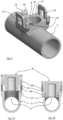
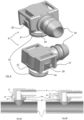
- external connecting pipe 28 is coupled to a connector 8 which is configured to connect to secondary aperture 4, thereby allowing a fluid flow.
- Connector 8 is internally hollow to allow such fluid flow.
- Connector 8 has a male portion 12 adapted to fit into secondary aperture 4.
- Secondary aperture 4 has a seat matching the shape of male portion 12.
- gasket 14 is mounted to male portion 12.
- Connector 8 and external connecting pipe 28 may be two distinct parts, or else they may be made as one piece.
- connector 8 is made from polymeric material, in particular by means of an injection moulding process.
- connector 8 has a connection portion 18 for mating with external connecting pipe 28.
- external connecting pipe 28 is mounted radially external to connection portion 18, which has, conveniently, a "fir tree" shape.
- all connectors 8 have the same shape and size.
- connector 8 when it is mounted to secondary aperture 4, connector 8 is configured to prevent the rotation of said connector 8 about an axis of insertion of connector 8 into secondary aperture 4. Therefore, when the connector 8 is mounted to pipe 8, it 8 cannot rotate.
- pipe 2 and connector 8 have abutment portions that prevent such rotation.
- connector 8 and pipe 2 are so configured that connector 8 can only be fitted into secondary aperture 4 with one or more predefined orientations. It is thus possible, advantageously, to prevent an incorrect assembly of connector 8 and pipe 2.
- pipe 2 and connector 8 are constructed in compliance with a "poka-yoke" system. In more detail, there is only one correct orientation with which connector 8 can be fitted to pipe 2 at secondary aperture 4.
- connector 8 comprises at least one tab 20 adapted to fit into a respective aperture 22 on pipe 2.
- the one or more apertures 22 are located in proximity to secondary aperture 4.
- tabs 20 become deformed and snap into place as they reach respective apertures 22.
- the two apertures 22 and the two tabs 20 are arranged symmetrically with respect to secondary aperture 4, and particularly also with respect to male portion 12.
- pipe 2 comprises at least one tab 20 adapted to fit into a respective aperture 22 on connector 8.
- pipe 2 comprises further clip-type means in addition to the system made up of aperture 22 and tab 20.
- connector 8 and/or pipe 2 comprise secondary tabs 24 having respective indentations 26 configured to engage with respective indentations provided on pipe 2 or, respectively, on connector 8. Secondary tabs 24 are intended to become elastically deformed to permit mutual engagement between the indentations.
- pipe 2 has, near secondary aperture 4, three secondary tabs 24, each one having its own indentation 26.
- Connector 8 has indentations 27 adapted to engage with indentations 26 of secondary tabs 24.
- the two apertures 22 are symmetrical with respect to secondary aperture 4.
- Secondary aperture 4 and male portion 12 shown in the drawings are circular in shape.
- flat face 32 has four edges.
- One secondary tab 24 is located on a first edge
- two secondary tabs 24 are located on a second edge, opposite to the first one
- each one of the other two edges comprises a respective aperture 22. Therefore, the two tabs 22 are disposed on two opposite edges.
- secondary tabs 24 on the second edge are located near the lateral ends of said second edge.
- the four edges form a rectangle or a square.
- secondary tabs 24 are disposed asymmetrically (in particular, with radial asymmetry) with respect to secondary aperture 4. This advantageously results in connector 8 being engageable with secondary aperture 4 in one way only, preventing the components from being assembled together with a wrong mutual orientation.
- the present invention also relates to an electric vehicle, e.g. a car, comprising a cooling system for the electric battery of the same, wherein the cooling system comprises at least one cooling element 1.
- the electric vehicle may include one or more electric batteries, wherein the cooling system is configured to cool such batteries.
- the vehicle may be either a fully electric vehicle or a hybrid vehicle.
Landscapes
- Engineering & Computer Science (AREA)
- General Engineering & Computer Science (AREA)
- Mechanical Engineering (AREA)
- Manufacturing & Machinery (AREA)
- Chemical & Material Sciences (AREA)
- Chemical Kinetics & Catalysis (AREA)
- Electrochemistry (AREA)
- General Chemical & Material Sciences (AREA)
- Electric Propulsion And Braking For Vehicles (AREA)
- Secondary Cells (AREA)
Applications Claiming Priority (1)
| Application Number | Priority Date | Filing Date | Title |
|---|---|---|---|
| IT102022000013153A IT202200013153A1 (it) | 2022-06-22 | 2022-06-22 | Elemento di raffreddamento per un componente elettrico, in particolare per una batteria elettrica di un veicolo elettrico o ibrido. |
Publications (1)
| Publication Number | Publication Date |
|---|---|
| EP4296553A1 true EP4296553A1 (de) | 2023-12-27 |
Family
ID=83188856
Family Applications (1)
| Application Number | Title | Priority Date | Filing Date |
|---|---|---|---|
| EP23180234.9A Pending EP4296553A1 (de) | 2022-06-22 | 2023-06-20 | Kühlelement für eine elektrische komponente, insbesondere für eine elektrische batterie eines elektro- oder hybridfahrzeugs |
Country Status (4)
| Country | Link |
|---|---|
| US (1) | US20240044431A1 (de) |
| EP (1) | EP4296553A1 (de) |
| CN (1) | CN220544010U (de) |
| IT (1) | IT202200013153A1 (de) |
Citations (5)
| Publication number | Priority date | Publication date | Assignee | Title |
|---|---|---|---|---|
| DE10211200A1 (de) * | 2002-03-14 | 2003-09-25 | Volkswagen Ag | Einweg-Steckverbinder für Schlauch- oder Rohrsysteme |
| US20080078464A1 (en) * | 2006-09-15 | 2008-04-03 | Trw Automotive Electronics & Components Gmbh & Co. Kg | Tube system, tube including a sealing element, and method of producing an assembly unit formed of a tube and a sealing element |
| US20090256355A1 (en) * | 2003-09-12 | 2009-10-15 | Value Plastics, Inc. | Releasable connection assembly for joining tubing sections |
| US20190339028A1 (en) * | 2018-05-02 | 2019-11-07 | Akwel | Fluid inlet-outlet manifold |
| WO2019220050A1 (fr) * | 2018-05-16 | 2019-11-21 | Akwel | Dispositif et système de raccordement fluidique |
Family Cites Families (16)
| Publication number | Priority date | Publication date | Assignee | Title |
|---|---|---|---|---|
| US5897142A (en) * | 1996-12-19 | 1999-04-27 | Itt Automotive, Inc. | Push-to-release quick connector |
| US6834888B2 (en) * | 2003-02-04 | 2004-12-28 | Flow-Rite Controls, Ltd. | Connector |
| DE102004060225A1 (de) * | 2004-12-15 | 2006-06-22 | Volkswagen Ag | Verbindungsanordnung mit einem Verbindungselement für zumindest im Verbindungsbereich koaxial verlaufende Bauteile |
| FR2881811B1 (fr) * | 2005-02-10 | 2007-04-20 | Legris Sa | Dispositif de raccordement instantane avec moyen de verrouillage et/ou de deconnexion |
| DE102005019044A1 (de) * | 2005-04-23 | 2006-10-26 | Luk Lamellen Und Kupplungsbau Beteiligungs Kg | Steckkupplung |
| DE202005015966U1 (de) * | 2005-10-10 | 2007-02-15 | Voss Automotive Gmbh | Steckverbinder für Medienleitungen |
| US7658420B2 (en) * | 2006-07-13 | 2010-02-09 | Parker-Hannifin Corporation | Quick-connect fitting with unlocking ring |
| FR3047059B1 (fr) * | 2016-01-26 | 2018-01-19 | Saint-Gobain Performance Plastics France | Ensemble de raccord pour tube |
| EP3952976A4 (de) * | 2019-04-09 | 2022-12-28 | NxStage Medical, Inc. | Verfahren, vorrichtungen und systeme zum koppeln von flüssigkeitsleitungen |
| FR3098566B1 (fr) * | 2019-07-12 | 2021-06-11 | Hutchinson | Dispositif de raccordement fluidique |
| US11698157B2 (en) * | 2020-07-24 | 2023-07-11 | Cooper-Standard Automotive Inc. | Quick connector latch verification utilizing a scannable code |
| FR3113936B1 (fr) * | 2020-09-09 | 2022-08-19 | A Raymond Et Cie | Dispositif de raccordement entre un conduit et une embase |
| CN115702305A (zh) * | 2020-11-11 | 2023-02-14 | J·韦斯特 | 管道配件 |
| US12163610B2 (en) * | 2021-03-18 | 2024-12-10 | Ti Group Automotive Systems, Llc | Quick connector with verification |
| US12398835B2 (en) * | 2021-11-05 | 2025-08-26 | Colder Products Company | Fluid couplings |
| CN114615871B (zh) * | 2022-03-31 | 2023-09-29 | 上海顺诠科技有限公司 | 一种液冷机柜分水器及液冷机柜 |
-
2022
- 2022-06-22 IT IT102022000013153A patent/IT202200013153A1/it unknown
-
2023
- 2023-06-20 EP EP23180234.9A patent/EP4296553A1/de active Pending
- 2023-06-21 US US18/339,180 patent/US20240044431A1/en active Pending
- 2023-06-25 CN CN202321612250.1U patent/CN220544010U/zh active Active
Patent Citations (5)
| Publication number | Priority date | Publication date | Assignee | Title |
|---|---|---|---|---|
| DE10211200A1 (de) * | 2002-03-14 | 2003-09-25 | Volkswagen Ag | Einweg-Steckverbinder für Schlauch- oder Rohrsysteme |
| US20090256355A1 (en) * | 2003-09-12 | 2009-10-15 | Value Plastics, Inc. | Releasable connection assembly for joining tubing sections |
| US20080078464A1 (en) * | 2006-09-15 | 2008-04-03 | Trw Automotive Electronics & Components Gmbh & Co. Kg | Tube system, tube including a sealing element, and method of producing an assembly unit formed of a tube and a sealing element |
| US20190339028A1 (en) * | 2018-05-02 | 2019-11-07 | Akwel | Fluid inlet-outlet manifold |
| WO2019220050A1 (fr) * | 2018-05-16 | 2019-11-21 | Akwel | Dispositif et système de raccordement fluidique |
Also Published As
| Publication number | Publication date |
|---|---|
| US20240044431A1 (en) | 2024-02-08 |
| IT202200013153A1 (it) | 2023-12-22 |
| CN220544010U (zh) | 2024-02-27 |
Similar Documents
| Publication | Publication Date | Title |
|---|---|---|
| JP4130512B2 (ja) | 熱交換器 | |
| US12139005B2 (en) | Component node and a component carrier for the component node | |
| US3207216A (en) | Heat exchanger | |
| KR102587118B1 (ko) | 커넥터 소켓, 커넥터 조립체, 냉각 플레이트 및 커넥터 소켓을 포함하는 냉각 시스템 | |
| CA3118968C (en) | Connector assembly, sheet metal plate for use with such an assembly and a cooling system including such an assembly | |
| KR101819488B1 (ko) | 냉각 모듈 및 조립 방법 | |
| US5467818A (en) | Heat exchanger | |
| EP4557460B1 (de) | Flüssigkeitskühlanordnung und batteriepack | |
| US11658357B2 (en) | Device for cooling batteries and associated production method | |
| EP4296553A1 (de) | Kühlelement für eine elektrische komponente, insbesondere für eine elektrische batterie eines elektro- oder hybridfahrzeugs | |
| KR20200051833A (ko) | 배터리 열 관리용 매니폴드 세그먼트 및 그 어셈블리 | |
| US11280560B1 (en) | Heat exchanger with two-piece through fittings | |
| JPH04268199A (ja) | 熱交換器 | |
| US6129146A (en) | Manifold for a brazed radiator | |
| US12431558B2 (en) | Cooling module for batteries of an electric or hybrid vehicle | |
| US8651533B2 (en) | Duct mating assembly | |
| US4332068A (en) | Heat exchanger assembly | |
| JP2000006646A (ja) | 車両用空調装置 | |
| WO2011039563A1 (en) | A heat exchanger | |
| US20210180883A1 (en) | Heat exchanger with one-piece through fittings | |
| CN222527112U (zh) | 管路法兰的接头连接结构、车辆热管理系统及车辆 | |
| CN222380671U (zh) | 电池包和具有其的动力装置 | |
| CA1122203A (en) | Heat exchanger assembly | |
| CN222953155U (zh) | 电池装置及用电装置 | |
| JP2025117130A (ja) | 熱交換器及び熱交換システム |
Legal Events
| Date | Code | Title | Description |
|---|---|---|---|
| PUAI | Public reference made under article 153(3) epc to a published international application that has entered the european phase |
Free format text: ORIGINAL CODE: 0009012 |
|
| STAA | Information on the status of an ep patent application or granted ep patent |
Free format text: STATUS: THE APPLICATION HAS BEEN PUBLISHED |
|
| AK | Designated contracting states |
Kind code of ref document: A1 Designated state(s): AL AT BE BG CH CY CZ DE DK EE ES FI FR GB GR HR HU IE IS IT LI LT LU LV MC ME MK MT NL NO PL PT RO RS SE SI SK SM TR |
|
| STAA | Information on the status of an ep patent application or granted ep patent |
Free format text: STATUS: REQUEST FOR EXAMINATION WAS MADE |
|
| 17P | Request for examination filed |
Effective date: 20240626 |
|
| RBV | Designated contracting states (corrected) |
Designated state(s): AL AT BE BG CH CY CZ DE DK EE ES FI FR GB GR HR HU IE IS IT LI LT LU LV MC ME MK MT NL NO PL PT RO RS SE SI SK SM TR |
|
| STAA | Information on the status of an ep patent application or granted ep patent |
Free format text: STATUS: EXAMINATION IS IN PROGRESS |
|
| 17Q | First examination report despatched |
Effective date: 20250612 |