EP4296579A1 - Lampe d'espace de cuisson et appareil de cuisson doté d'un espace de cuisson et d'au moins une lampe d'espace de cuisson - Google Patents
Lampe d'espace de cuisson et appareil de cuisson doté d'un espace de cuisson et d'au moins une lampe d'espace de cuisson Download PDFInfo
- Publication number
- EP4296579A1 EP4296579A1 EP23175408.6A EP23175408A EP4296579A1 EP 4296579 A1 EP4296579 A1 EP 4296579A1 EP 23175408 A EP23175408 A EP 23175408A EP 4296579 A1 EP4296579 A1 EP 4296579A1
- Authority
- EP
- European Patent Office
- Prior art keywords
- light
- cooking
- designed
- cooking space
- light guide
- Prior art date
- Legal status (The legal status is an assumption and is not a legal conclusion. Google has not performed a legal analysis and makes no representation as to the accuracy of the status listed.)
- Withdrawn
Links
- 238000010411 cooking Methods 0.000 title claims abstract description 209
- 230000005540 biological transmission Effects 0.000 claims abstract description 27
- 230000008878 coupling Effects 0.000 claims abstract description 19
- 238000010168 coupling process Methods 0.000 claims abstract description 19
- 238000005859 coupling reaction Methods 0.000 claims abstract description 19
- 239000005388 borosilicate glass Substances 0.000 claims description 5
- 239000011521 glass Substances 0.000 claims description 4
- 238000009434 installation Methods 0.000 claims description 4
- 239000007787 solid Substances 0.000 claims description 3
- 238000011161 development Methods 0.000 description 23
- 230000018109 developmental process Effects 0.000 description 23
- 238000004519 manufacturing process Methods 0.000 description 8
- 238000010276 construction Methods 0.000 description 6
- 230000008901 benefit Effects 0.000 description 3
- 238000005516 engineering process Methods 0.000 description 2
- 238000009413 insulation Methods 0.000 description 2
- 239000000463 material Substances 0.000 description 2
- 230000015572 biosynthetic process Effects 0.000 description 1
- 239000000969 carrier Substances 0.000 description 1
- 238000001816 cooling Methods 0.000 description 1
- 230000007423 decrease Effects 0.000 description 1
- 230000001419 dependent effect Effects 0.000 description 1
- 238000000605 extraction Methods 0.000 description 1
- 230000004907 flux Effects 0.000 description 1
- 238000005286 illumination Methods 0.000 description 1
- 230000000750 progressive effect Effects 0.000 description 1
- 230000009467 reduction Effects 0.000 description 1
Images


Classifications
-
- F—MECHANICAL ENGINEERING; LIGHTING; HEATING; WEAPONS; BLASTING
- F24—HEATING; RANGES; VENTILATING
- F24C—DOMESTIC STOVES OR RANGES ; DETAILS OF DOMESTIC STOVES OR RANGES, OF GENERAL APPLICATION
- F24C15/00—Details
- F24C15/008—Illumination for oven cavities
Definitions
- the invention relates to a cooking appliance of the type mentioned in the preamble of claim 1.
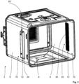
- Such cooking space lights and cooking devices are already known from the prior art in a variety of embodiments and include a housing, a cooking space arranged in the housing and delimited by cooking space walls, and at least one cooking space light arranged between at least one of the cooking space walls and the housing, the cooking space light a light guide with a light coupling surface for coupling visible light of at least one light source of the cooking chamber lamp into the light guide and a light decoupling surface for illuminating the cooking chamber, and in which a lighting opening corresponding to the light coupling surface is arranged in the cooking chamber wall assigned to this cooking chamber lamp.
- the invention therefore presents the problem of improving a cooking space light for a cooking appliance and a cooking appliance with a cooking space and at least one cooking space light.
- a cooking appliance with a cooking chamber light according to the features of patent claim 1, which is characterized in that the light guide is designed as a two-part light guide formed from a first part and a second part, the first part of the light guide being the The light input surface facing the light source and a first light transmission surface and the second part of the light guide have a second light transmission surface and the light output surface facing the cooking chamber, and wherein the first light transmission surface and the second light transmission surface transmit light and are spaced apart from one another for coupling the light from the first part into the second part are arranged opposite each other, and wherein the second part of the light guide is designed and can be arranged in the cooking appliance in such a way that the light coupled into the second part of the light guide can be deflected by means of the second part of the light guide in the direction of an interior of the cooking space and at the same time in the direction of a rear wall of the cooking space .
- the advantage that can be achieved with the invention is, in particular, that a cooking space light for a cooking appliance and a cooking appliance with a cooking space and at least one cooking space light are improved. Due to the design of the cooking chamber light and the cooking appliance according to the invention, on the one hand, qualitatively and quantitatively good and, on the other hand, energy-efficient lighting of the cooking chamber is possible. For example, using the Invention enables, on the one hand, homogeneous and, on the other hand, essentially glare-free lighting of the cooking space for a user of the cooking appliance according to the invention. In addition, the construction and production of the cooking appliance according to the invention, in particular with regard to the at least one cooking chamber light, is significantly simplified.
- the cooking space light according to the invention and the cooking appliance according to the invention can be freely selected within wide suitable limits according to type, functionality, material and dimensions. See also the relevant comments in the introduction to the description.
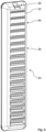
- the second part has a plurality of light deflection means on a rear wall of the second part facing away from the cooking space in an installation position of the cooking space light, in which the cooking space light is installed in the cooking appliance, preferably that the light deflection means are uniform are arranged distributed over a height of the cooking chamber, particularly preferred that the second part is designed as a single solid body.
- the second part with its light deflection means can be implemented in a particularly simple manner in terms of construction, production technology and optics.
- the preferred embodiment of this development is also particularly conducive to homogeneous illumination of the cooking space.
- the second part and its functions are particularly easy to produce and handle.
- the light deflection means each have a coarse structure and a fine structure arranged on the coarse structure, preferably that the elements of the coarse structure start from the second light transmission surface in the direction of the end of the second part opposite the second light transmission surface become steadily larger, particularly preferably that the elements of the coarse structure form a sawtooth structure overall in a vertical section through the second part.
- the second part can be implemented in a very simple manner in terms of construction and production technology, with different light-optical functionalities being made possible by means of the coarse structure on the one side and the fine structure on the other side.
- the preferred embodiment of this development also has the further advantage that the size of the elements Rough structure can be adapted to the luminous flux that decreases when passing through the second part due to the progressive light extraction. This can be implemented particularly easily using the particularly preferred embodiment of this development.
- An advantageous development of the last-mentioned development of the cooking chamber light according to the invention provides that the coarse structure is designed to deflect the light towards the interior of the cooking chamber and the fine structure is designed to deflect the light towards the rear wall of the cooking chamber.
- the respective structure can be specifically adapted to the requirements of the corresponding light-optical function.
- the respective coarse structure is designed as an outer surface of the rear wall which is arranged obliquely relative to the light coupled into the second part, preferably that the respective coarse structure is designed as a single slope. This significantly simplifies the construction and production of the rough structure. This applies in particular to the preferred embodiment of this development.
- the respective fine structure is designed as a plurality of outer surfaces of the rear wall which are arranged obliquely relative to the light output surface in a horizontal section through the second part, preferably that the respective fine structure is designed as a sawtooth structure is. In this way, the construction and production of the fine structure is also significantly simplified. This applies in particular to the preferred embodiment of this development.
- the light decoupling surface is formed on a front wall of the second part opposite the rear wall, preferably that the front wall has a light decoupling structure, particularly preferably that the light decoupling structure is designed as a honeycomb structure.
- the rear wall with the light deflection means on one side and the light decoupling surface for decoupling the light from the second part on the other side are assigned to one another in a particularly advantageous light-optical manner.
- a substantially homogeneous appearance of the light decoupling surface is made possible, so that, for example, small cracks in the second part, which are caused by cooling of the second part during its production or the like, are concealed by means of the light decoupling structure.
- Particularly advantageous for this is the design of the light decoupling structure as a honeycomb structure.
- the cooking appliance according to the invention can be freely selected within wide suitable limits.
- An advantageous development of the cooking appliance according to the invention provides that the light source of the cooking space lamp is arranged above the cooking space and the second part of the light guide of the cooking space light is arranged to the side of the cooking space in the housing.
- the light source and corresponding electronics of the cooking chamber light outside the aforementioned hot area in the aforementioned cold area of the cooking appliance.
- the light source and its electronics can be combined with other electronics of the cooking appliance, which are usually arranged above the cooking space. Accordingly, there are structural advantages which can, for example, lead to a reduction in the number of components and/or to a saving of installation space.
- a further advantageous development of the cooking appliance according to the invention provides that the first part of the light guide of the cooking chamber light is designed as a light guide rod, preferably as a circular cylinder, with the light coupling surface being arranged on one end face and the first light transmission surface being arranged on another end face of the light guide rod.
- the first part of the light guide is designed to be functional and very space-saving. This applies in particular to the preferred embodiment of this development.
- thermo insulation is made possible, for example by decoupling the above-mentioned cold area from the above-mentioned hot area.
- the required microwave tightness of the cooking appliance can also be achieved very easily.
- the light decoupling surface is designed as a substantially rectangular surface, preferably that the light decoupling surface extends at least over 50% of the height of the cooking space. In this way, the lighting of the cooking space is further improved by means of the cooking space light. This applies in particular to food carriers inserted into the cooking space to hold food to be cooked.
- the phrase “essentially rectangular” here means that the aforementioned light output surface can also be rounded at the corners, for example.
- a further advantageous development of the cooking appliance according to the invention provides that the first part and/or the second part are each designed as a glass part, preferably that the first part and/or the second part are each designed as a borosilicate glass part are/is.
- the first part and/or the second part is made of material that is particularly advantageous for the function of the light guide. This applies particularly to the preferred embodiment of this development and in particular with regard to the formation of the second part of the light guide made of borosilicate glass, since the second part is usually arranged in the aforementioned hot area of the cooking appliance.
- the first and/or second part it is also possible for the first and/or second part to be made of a plastic, for example. However, it is then necessary to provide a glass cover or the like to cover the lighting opening between the cooking chamber on one side and the light output surface on the other side.
- the light sources 16 of the respective cooking chamber light 10 are each arranged above the cooking chamber 8 and the second part 24 of the light guide 12 of the respective cooking chamber light 10 is arranged to the side of the cooking chamber 8 in the housing 4. Accordingly, the light sources 16 with electronics (not shown) of the respective light source 16 are arranged in an area of the cooking appliance 2 that is much cooler than the second parts 24 of the respective light guide 12.
- the first part 22 of the light guide 12 of the respective cooking chamber light 10 is designed as a light guide rod, namely as a circular cylinder, with the light coupling surface 14 being arranged on one end face and the first light transmission surface 26 on another end face of the light guide rod 22.
- the second part 24 of the light guide 12 of the respective cooking chamber light 10 has an im Compared to the corresponding first part 22, it has a larger cross-sectional area, namely a cross-sectional area that is at least twice as large as the respective first part 22.
- the two cooking space lights 10 arranged on cooking space walls 6 designed as opposite side walls are here, on the one hand, designed analogously to one another and, on the other hand, arranged on the cooking space 8 corresponding to one another.
- the explanations therefore refer to both cooking space lights 10.
- the cooking space lights 10 can largely be manufactured from identical parts. In addition, this also reduces warehousing and logistics.
- the respective fine structure 40 is as a plurality of in one in the Fig. 9 shown horizontal section through the second part 24 is formed obliquely arranged outer surfaces of the rear wall 34 relative to the light decoupling surface 18, the respective fine structure 40 being designed as a sawtooth structure.
- the design of the cooking appliance 2 according to the invention Due to the design of the cooking appliance 2 according to the invention, on the one hand, qualitatively and quantitatively good and, on the other hand, energy-efficient lighting of the cooking chamber 8 is made possible.
- a homogeneous and, on the other hand, at the same time essentially for a user, not shown, of the cooking appliance 2 Glare-free lighting of the cooking space 8 is possible.
- the construction and production of the cooking appliance 2 according to the invention, in particular with regard to the cooking chamber lights 10, is significantly simplified.
- the invention is not limited to the present exemplary embodiment.
- the invention can also be used advantageously in other cooking appliances with a cooking space. See, for example, the relevant statements in the introduction to the description.
- the cooking appliance according to the invention is not limited to the structural and manufacturing details of the exemplary embodiment explained.
Landscapes
- Engineering & Computer Science (AREA)
- Chemical & Material Sciences (AREA)
- Combustion & Propulsion (AREA)
- Mechanical Engineering (AREA)
- General Engineering & Computer Science (AREA)
- Electric Ovens (AREA)
Applications Claiming Priority (1)
| Application Number | Priority Date | Filing Date | Title |
|---|---|---|---|
| BE20225487A BE1030652B1 (de) | 2022-06-21 | 2022-06-21 | Garraumleuchte und Gargerät mit einem Garraum und mindestens einer Garraumleuchte |
Publications (1)
| Publication Number | Publication Date |
|---|---|
| EP4296579A1 true EP4296579A1 (fr) | 2023-12-27 |
Family
ID=83995627
Family Applications (1)
| Application Number | Title | Priority Date | Filing Date |
|---|---|---|---|
| EP23175408.6A Withdrawn EP4296579A1 (fr) | 2022-06-21 | 2023-05-25 | Lampe d'espace de cuisson et appareil de cuisson doté d'un espace de cuisson et d'au moins une lampe d'espace de cuisson |
Country Status (2)
| Country | Link |
|---|---|
| EP (1) | EP4296579A1 (fr) |
| BE (1) | BE1030652B1 (fr) |
Citations (4)
| Publication number | Priority date | Publication date | Assignee | Title |
|---|---|---|---|---|
| US6637923B2 (en) * | 2001-08-15 | 2003-10-28 | Koito Manufacturing Co., Ltd. | Vehicular lamp with LED light source having uniform brightness |
| DE102015225992A1 (de) * | 2015-12-18 | 2017-06-22 | BSH Hausgeräte GmbH | Speisenbehandlungsgerät |
| WO2018041531A1 (fr) * | 2016-09-02 | 2018-03-08 | Arcelik Anonim Sirketi | Four comprenant un moyen d'éclairage |
| US10508815B2 (en) * | 2016-08-23 | 2019-12-17 | Emz-Hanauer Gmbh & Co. Kgaa | Domestic oven with muffle lighting |
-
2022
- 2022-06-21 BE BE20225487A patent/BE1030652B1/de not_active IP Right Cessation
-
2023
- 2023-05-25 EP EP23175408.6A patent/EP4296579A1/fr not_active Withdrawn
Patent Citations (4)
| Publication number | Priority date | Publication date | Assignee | Title |
|---|---|---|---|---|
| US6637923B2 (en) * | 2001-08-15 | 2003-10-28 | Koito Manufacturing Co., Ltd. | Vehicular lamp with LED light source having uniform brightness |
| DE102015225992A1 (de) * | 2015-12-18 | 2017-06-22 | BSH Hausgeräte GmbH | Speisenbehandlungsgerät |
| US10508815B2 (en) * | 2016-08-23 | 2019-12-17 | Emz-Hanauer Gmbh & Co. Kgaa | Domestic oven with muffle lighting |
| WO2018041531A1 (fr) * | 2016-09-02 | 2018-03-08 | Arcelik Anonim Sirketi | Four comprenant un moyen d'éclairage |
Also Published As
| Publication number | Publication date |
|---|---|
| BE1030652B1 (de) | 2024-01-29 |
| BE1030652A1 (de) | 2024-01-23 |
Similar Documents
| Publication | Publication Date | Title |
|---|---|---|
| DE202015104575U1 (de) | Haushaltsgerät und Haushaltsgeräteleuchte | |
| EP2703735B1 (fr) | Appareil électroménager avec un appareil à micro-ondes | |
| EP4033861A1 (fr) | Appareil de cuisson à micro-ondes pourvu d'éclairage à del adapté | |
| DE102016203180A1 (de) | Haushaltsgerät mit einer Leuchte zur Beleuchtung einer Griffmulde einer Tür | |
| DE102018111092A1 (de) | Beleuchtungsvorrichtung für ein Gargerät mit einem Lichtleiter | |
| EP3841329A1 (fr) | Porte pour un appareil de cuisson pourvue d'une armature séparée pourvue d'une poignée encastrée, et appareil de cuisson pourvu d'une porte | |
| EP4386267B1 (fr) | Lampe pour appareil de cuisson | |
| EP1923621A1 (fr) | Dispositif d'éclairage pour un appareil ménager doté d'un espace de traitement | |
| EP2746674B1 (fr) | Appareil de cuisson | |
| BE1030652B1 (de) | Garraumleuchte und Gargerät mit einem Garraum und mindestens einer Garraumleuchte | |
| EP4130579A1 (fr) | Procédé de fabrication d'un appareil de cuisson et appareil de cuisson | |
| BE1029645B1 (de) | Gargerät, umfassend einen Garraum und mindestens eine Garraumleuchte | |
| DE19506651C1 (de) | Innenleuchte für Fahrzeuge | |
| EP0847889A2 (fr) | Unité d'affichage | |
| EP2746676A1 (fr) | Dispositif d'éclairage pour un appareil de cuisson et appareil de cuisson | |
| DE10037881A1 (de) | Tür für ein Haushaltsgerät, insbesondere einen Haushaltsgarofen | |
| EP4033156B1 (fr) | Appareil de cuisson pourvu de plaque de maintien pour un luminaire d'appareil de cuisson | |
| DE10122878B4 (de) | Beleuchtungseinrichtung für Backöfen | |
| EP3147608B1 (fr) | Module d'éclairage pour un appareil ménager et appareil ménager comprenant ledit module d'éclairage | |
| DE102022106969A1 (de) | Möbel mit Beleuchtung einer Aussparung in einer Möbelfront | |
| DE102024104622A1 (de) | Lichtleitkanal für eine Beleuchtungsvorrichtung und Beleuchtungsvorrichtung für ein Haushaltsgerät | |
| EP3388747B1 (fr) | Four de cuisson | |
| DE202023101647U1 (de) | Gargeräteleuchte | |
| DE102020119938B3 (de) | Gargeschirr mit einer Ausgabeeinheit und Verfahren zum Betrieb des Gargeschirrs | |
| DE102020117867A1 (de) | Tragsystem zur Anordnung eines Gargutträgers in einem Garraum eines Gargeräts und Gargerät |
Legal Events
| Date | Code | Title | Description |
|---|---|---|---|
| PUAI | Public reference made under article 153(3) epc to a published international application that has entered the european phase |
Free format text: ORIGINAL CODE: 0009012 |
|
| STAA | Information on the status of an ep patent application or granted ep patent |
Free format text: STATUS: THE APPLICATION HAS BEEN PUBLISHED |
|
| AK | Designated contracting states |
Kind code of ref document: A1 Designated state(s): AL AT BE BG CH CY CZ DE DK EE ES FI FR GB GR HR HU IE IS IT LI LT LU LV MC ME MK MT NL NO PL PT RO RS SE SI SK SM TR |
|
| STAA | Information on the status of an ep patent application or granted ep patent |
Free format text: STATUS: THE APPLICATION IS DEEMED TO BE WITHDRAWN |
|
| 18D | Application deemed to be withdrawn |
Effective date: 20240628 |