EP4296702A1 - Système de bobines de gradient auto-blindées divisées doté d'un système d'alimentation permettant de régler individuellement les courants des groupes de sous-bobines - Google Patents
Système de bobines de gradient auto-blindées divisées doté d'un système d'alimentation permettant de régler individuellement les courants des groupes de sous-bobines Download PDFInfo
- Publication number
- EP4296702A1 EP4296702A1 EP22181052.6A EP22181052A EP4296702A1 EP 4296702 A1 EP4296702 A1 EP 4296702A1 EP 22181052 A EP22181052 A EP 22181052A EP 4296702 A1 EP4296702 A1 EP 4296702A1
- Authority
- EP
- European Patent Office
- Prior art keywords
- coil
- sub
- gradient
- gradient coil
- groups
- Prior art date
- Legal status (The legal status is an assumption and is not a legal conclusion. Google has not performed a legal analysis and makes no representation as to the accuracy of the status listed.)
- Pending
Links
Images


Classifications
-
- G—PHYSICS
- G01—MEASURING; TESTING
- G01R—MEASURING ELECTRIC VARIABLES; MEASURING MAGNETIC VARIABLES
- G01R33/00—Arrangements or instruments for measuring magnetic variables
- G01R33/20—Arrangements or instruments for measuring magnetic variables involving magnetic resonance
- G01R33/28—Details of apparatus provided for in groups G01R33/44 - G01R33/64
- G01R33/38—Systems for generation, homogenisation or stabilisation of the main or gradient magnetic field
- G01R33/385—Systems for generation, homogenisation or stabilisation of the main or gradient magnetic field using gradient magnetic field coils
-
- G—PHYSICS
- G01—MEASURING; TESTING
- G01R—MEASURING ELECTRIC VARIABLES; MEASURING MAGNETIC VARIABLES
- G01R33/00—Arrangements or instruments for measuring magnetic variables
- G01R33/20—Arrangements or instruments for measuring magnetic variables involving magnetic resonance
- G01R33/28—Details of apparatus provided for in groups G01R33/44 - G01R33/64
- G01R33/32—Excitation or detection systems, e.g. using radio frequency signals
- G01R33/36—Electrical details, e.g. matching or coupling of the coil to the receiver
-
- G—PHYSICS
- G01—MEASURING; TESTING
- G01R—MEASURING ELECTRIC VARIABLES; MEASURING MAGNETIC VARIABLES
- G01R33/00—Arrangements or instruments for measuring magnetic variables
- G01R33/20—Arrangements or instruments for measuring magnetic variables involving magnetic resonance
- G01R33/28—Details of apparatus provided for in groups G01R33/44 - G01R33/64
- G01R33/38—Systems for generation, homogenisation or stabilisation of the main or gradient magnetic field
- G01R33/385—Systems for generation, homogenisation or stabilisation of the main or gradient magnetic field using gradient magnetic field coils
- G01R33/3852—Gradient amplifiers; means for controlling the application of a gradient magnetic field to the sample, e.g. a gradient signal synthesizer
-
- G—PHYSICS
- G01—MEASURING; TESTING
- G01R—MEASURING ELECTRIC VARIABLES; MEASURING MAGNETIC VARIABLES
- G01R33/00—Arrangements or instruments for measuring magnetic variables
- G01R33/20—Arrangements or instruments for measuring magnetic variables involving magnetic resonance
- G01R33/28—Details of apparatus provided for in groups G01R33/44 - G01R33/64
- G01R33/38—Systems for generation, homogenisation or stabilisation of the main or gradient magnetic field
- G01R33/385—Systems for generation, homogenisation or stabilisation of the main or gradient magnetic field using gradient magnetic field coils
- G01R33/3858—Manufacture and installation of gradient coils, means for providing mechanical support to parts of the gradient-coil assembly
-
- G—PHYSICS
- G01—MEASURING; TESTING
- G01R—MEASURING ELECTRIC VARIABLES; MEASURING MAGNETIC VARIABLES
- G01R33/00—Arrangements or instruments for measuring magnetic variables
- G01R33/20—Arrangements or instruments for measuring magnetic variables involving magnetic resonance
- G01R33/28—Details of apparatus provided for in groups G01R33/44 - G01R33/64
- G01R33/42—Screening
- G01R33/421—Screening of main or gradient magnetic field
- G01R33/4215—Screening of main or gradient magnetic field of the gradient magnetic field, e.g. using passive or active shielding of the gradient magnetic field
-
- G—PHYSICS
- G01—MEASURING; TESTING
- G01R—MEASURING ELECTRIC VARIABLES; MEASURING MAGNETIC VARIABLES
- G01R33/00—Arrangements or instruments for measuring magnetic variables
- G01R33/20—Arrangements or instruments for measuring magnetic variables involving magnetic resonance
- G01R33/44—Arrangements or instruments for measuring magnetic variables involving magnetic resonance using nuclear magnetic resonance [NMR]
- G01R33/48—NMR imaging systems
- G01R33/54—Signal processing systems, e.g. using pulse sequences ; Generation or control of pulse sequences; Operator console
- G01R33/56—Image enhancement or correction, e.g. subtraction or averaging techniques, e.g. improvement of signal-to-noise ratio and resolution
- G01R33/565—Correction of image distortions, e.g. due to magnetic field inhomogeneities
- G01R33/56518—Correction of image distortions, e.g. due to magnetic field inhomogeneities due to eddy currents, e.g. caused by switching of the gradient magnetic field
Definitions
- the invention relates to a gradient coil system for use in a magnetic resonance device, comprising
- NMR nuclear magnetic resonance
- MRI magnetic resonance imaging
- B 0 field a strong background magnetic field
- RF radio frequency
- field gradient NMR also called pulsed field gradient NMR or PFG-NMR
- a gradient coil system generates locally inhomogeneous transient magnetic field, also called gradient coil magnetic field here, in addition to the background magnetic field.
- Both the background magnetic field and the gradient coil magnetic field are aligned along a main axis (also called z axis), and in general only the Bz components of said fields are relevant.
- the gradient coil magnetic field typically varies linearly in one or more axes (or gradient directions) x, y and/or z.
- NMR experiments typically apply pulse sequences wherein the gradient coil magnetic fields have to be switched rapidly. Then the electric current in the gradient coil system has to be switched on and off in a very short time, typically in the order of a few dozens of milliseconds. Further, gradient coil systems are required to provide strong magnetic fields within a limited space with low impact of Eddy currents.
- the gradient coil system may be equipped with a shielding coil.
- the shielding coil also weakens the gradient coil magnetic field in the target area.
- the gradient coil system may be designed with an increased number of coil windings, however this increases the inductance and resistance of the gradient coil system, what in turn reduces the switching speed that can be achieved, and increases the power consumption.
- a gradient coil system comprising a pair of coils arranged on a bobbin. Each coil comprises a number of element parts connected in parallel to a power source.
- the gradient coil system is intended to reduce the inductance.
- CN 107 957 565 A proposes a self-shielding gradient coil of an NMR spectrometer, with a main coil and a shielding coil coaxially arranged on the outer side of the main coil.
- the windings of the main coil are composed of a plurality of stages of main coil upper windings and main coil lower windings symmetrically arranged up and down. Each stage of the main coil winding corresponds to an independent driving current channel.
- a gradient coil comprising a main coil and a split gradient shield coil connected in series.
- the sub coils of the gradient shield coil are connected in parallel to each other.
- US 2013 299 182 A1 describes a gradient coils system wherein a main coil and a shielding coil comprise a plurality of sub-coils each, and all the sub-coils are connected in series.
- both the main coil is subdivided into a plurality of main sub-coils
- the shielding coil is subdivided into a plurality of shielding sub-coils.
- These sub-coils are allocated to a plurality of sub-coil groups, with each sub-coil group comprising one of the main sub-coils and one of the shielding sub-coils electrically connected in series.
- the power supply system is capable of setting the electric current in each of the sub-coils individually.
- the inductivity and resistance of each sub-coil and of each sub-coil group can be kept relatively small. Further, the coil sub-groups can be decoupled fairly easily, in particular by keeping a sufficient separation along the z axis and/or along the gradient direction x or y or z. Thus, time for charging and decharging the sub-coil groups can be kept small, and fast switching times are possible. At the same time, the generated fields of the sub-coil groups add up in the target volume, and thus the generation of strong gradient coil magnetic fields is possible in the target volume.
- the respective main sub-coil and shielding sub-coil are typically located at basically the same position in z, and therefore a good shielding effect can be achieved for the respective sub-coil group.
- Low inductivity and resistance are obtained both for the respective main sub-coils and also for the shielding sub-coils, contributing to fast switching times, too.
- the power supply system allows choosing the electric operating current for each sub-coil group separately. In this way, it is possible to optimize the performance of the gradient coil system, in particular with respect to the generation (precision) of the desired gradient coil magnetic field and/or with respect to Eddy currents in neighbouring NMR components. More specifically, the electric currents may be set such that the desired profile of the gradient coil magnetic field or its first derivative, respectively, can be approximated with high accuracy, in particular wherein the first derivative of the gradient coil magnetic field is symmetrized with respect to a central point of the gradient coil system or the target volume inside the gradient coil system, respectively. In this way, manufacturing tolerances, construction defects or spatial inaccuracies of the windings may be compensated for.
- the shielding of the shielding coil as such already reduces Eddy currents in the outer surroundings of the gradient coil system. Further, by adjusting the electric currents individually, Eddy currents can be influenced such that artifacts in the NMR signal due to Eddy currents are suppressed or minimized, typically by minimizing remaining Eddy currents in the neighbouring NMR components altogether. In particular, the shielding fringe may be optimized. Even further, by adjusting the currents in the two halves of the gradient coils system with respect to the center point (z ⁇ 0 and z>0), Eddy current artifacts that cause phase distortions throughout an NMR spectrum can be minimized.
- gradient coil systems with a large number of windings and/or operated with strong currents can be used, while keeping the measurement quality high.
- the gradient coil system can be based on sub-coils arranged on cylindrical bobbins, or also on planar sub-coils.
- Typical gradient coil systems in accordance with the invention have a length (in z direction) of 50-80 mm, preferably of 60-75 mm.
- Typical outer diameters of a gradient coil system are 30-45 mm, preferably 35-40 mm.
- Typical wires for coil windings have a diameter of 0.2-1,0 mm, preferably 0.25-0.75 mm.
- a typical length (in z) of a sample measured is 10-25 mm.
- the magnetic field generated by the gradient coil system as a whole i.e. including the split main coil and including the split shielding coil
- the gradient coil magnetic field Bz varies as a function of space (position) along the gradient direction.
- the first derivative of the gradient coil magnetic field Bz, i.e. d Bz / dp, with p: variable of position of the chosen gradient direction, is sometimes called the "gradient” or "gradient field”.
- the gradient coil magnetic field Bz is generally pulsed, i.e. it is switched on and off within short time, typically on the order of a few microseconds.
- the power supply system comprises a common power supply unit and at least N-1 current adjustment units, in particular variable resistors, wherein the N sub-coil groups are connected to the common power supply unit, and the electric currents of each of the N sub-coil groups can be adjusted via the common power supply unit and the current adjustment units.
- the electric current (power) at one of the sub-coil groups is adjusted via the common power supply unit, and the electric currents (powers) at the other N-1 sub-coil groups is adjusted via the current adjustment units.
- the N sub-coil groups are connected in parallel to the common power supply unit, and in the at least N-1 sub-coil groups, a current adjustment unit is connected in series with the main sub-coil and the shielding sub-coil of the respective sub-coil group.
- the power supply system comprises N independent power supply units, wherein each of the N power supply units is connected to one of the N sub-coil groups.
- each power supply unit needs to provide only a part of the overall electric current, what in general allows particularly strong individual electric currents for each sub-coil group.
- connecting cables connecting the power supply system with the N sub-coil groups are arranged on one axial side of the gradient coil system only. This simplifies including the gradient coil system into an NMR probe (sometimes also called probehead) and insertion of the NMR probe into a bore of a cryostat, in particular wherein one end of the bore can be dedicated solely to the NMR probe or measurement equipment, and one end of the bore solely to the sample provision.
- NMR probe sometimes also called probehead
- the target volume of the gradient coil system has a center point, and the center point is located axially in between two axially neighbouring sub-coil groups of the N sub-coil groups.
- the number of the N sub-coil groups is even. Again, this setup has been proven in practice, and is particularly well suited for generating high strength gradient coil magnetic fields.
- N sub-coil groups are arranged symmetrically, in particular wherein the N sub-coil groups are arranged symmetrically with respect to a center point of the target volume or a mirror plane, wherein the mirror plane is perpendicular to the z-axis and comprises the center point of the target volume.
- This setup is well suited for generating gradient coil magnetic fields of high symmetry. Note that a mirror symmetry or a point symmetry or combined mirror/rotation symmetry may be used in the present invention.
- the N sub-coil groups are arranged asymmetrically, in particular wherein the N sub-coil groups are arranged asymmetrically with respect to both a center point of the target volume and a mirror plane, wherein the mirror plane is perpendicular to the z-axis and comprises the center point of the target volume.
- An asymmetric arrangement of the sub-coil groups may be advantageous for compensating an asymmetric design of NMR components neighbouring the gradient coils system radially and axially outside the gradient coil system.
- the number of windings of the main coil and/or the number of windings of the shielding coil is unequal on both axial sides of the center point.
- the gradient coil system is characterized in that for at least a majority of the sub-coil groups, preferably for all sub-coil groups, within a respective sub-coil group, a main coil winding direction of main coil windings is uniform, and a shielding coil winding direction of shielding coil windings is uniform, with the main coil winding direction being opposite to the shielding coil winding direction.
- Another embodiment provides that for at least a part of the sub-coil groups, within a respective sub-coil group, a main coil winding direction of main coil windings changes at least once, and/or a shielding coil winding direction of shielding coil windings changes at least once. In other words there is at least on main coil winding and/or at least one shielding coil winding with opposite current direction within the respective sub-coil.
- a main coil winding direction of main coil windings changes at least once
- a shielding coil winding direction of shielding coil windings changes at least once.
- Such a design can be useful for fine-tuning the gradient coil magnetic field and/or the distribution of Eddy currents in the neighbouring NMR components.
- M ij ⁇ r ⁇ L i
- r applies: r ⁇ 0.4, preferably r ⁇ 0.2, most preferably r ⁇ 0.06.
- the gradient direction of the gradient coil system is parallel to the z-axis, and the gradient coil system comprises at least four sub-coil groups. With four or more sub-coil groups, higher order types of gradients in the gradient coil magnetic field may be established in z direction as gradient direction.
- a gradient coil assembly for use in a magnetic resonance device, comprising at least two above described inventive gradient coil systems,
- the gradient coil assembly is capable of generating two (or more) perpendicular "gradients", for example for obtaining spatially resolved information about the sample.
- the at (least two) different gradient directions may be chosen from the Cartesian coordinate directions x, y and z.
- three gradient coils systems with orthogonal gradient directions x, y, z can be combined.
- the multiple gradient coil systems are arranged in a nested way. Note that for the different gradient coil systems or gradient directions, respectively, different variants of adjusting the quality of the magnetic field generated by the respective gradient coil system may be applied, if desired (see below).
- a probe for NMR spectroscopy or magnetic resonance imaging (MRI) or diffusion measurements using magnetic resonance comprising an RF transmitting and receiving system, and at least one above described inventive gradient coil system or an above described inventive gradient coil assembly.
- an NMR spectrometer or magnetic resonance imaging apparatus or magnetic resonance diffusion measurement apparatus comprising an above described inventive probe and a background magnet for generating a static magnetic field B 0 along the z-axis in the target volume.
- the NMR spectrometer or MRI apparatus or MR diffusion measurement apparatus allows measurements of particularly high quality, in particular high spectral resolution.
- a preferred variant of the inventive method provides that the electric currents of the N sub-coil groups are adjusted such that a residual profile in z direction of a residual magnetic flux of the gradient coil magnetic field generated by the gradient coil system in a plane perpendicular to the z axis and in an area larger than and including a cross-section of the gradient coil system is set at least approximately to a desired residual profile.
- a desired residual profile depends on the overall design of the NMR probe or maybe even of the NMR spectrometer.
- the desired residual profile can be a calculated residual profile obtained with an ideal gradient coil system without manufacturing tolerances, and optionally also taking into account influence from the probe and other magnet components.
- the electric currents of the N sub-coil groups are adjusted such that a residual profile in z direction of a residual magnetic flux of the gradient coil magnetic field generated by the gradient coil system in a plane perpendicular to the z axis and in an area larger than and including a cross-section of the gradient coil system is made antisymmetric with respect to a center point of the target volume.
- a residual profile in z direction of a residual magnetic flux of the gradient coil magnetic field generated by the gradient coil system in a plane perpendicular to the z axis and in an area larger than and including a cross-section of the gradient coil system is made antisymmetric with respect to a center point of the target volume.
- At least one calibration measurement of the residual profile is made, in particular wherein an induced voltage generated during switching of the electric currents of the N sub-coil groups is measured via a pick-up loop at a fixed radius c, with the fixed radius c of the pick-up loop being larger than a maximum outer radius b of the gradient coil system.
- the residual profile can be obtained in a fast and simple way. Using the pick-up loop is simple and highly reliable. Note that in this calibration measurement, the sub-coil groups are operated with an alternating current, and the pick-up loop is moved along the z axis.
- the electric currents of the N sub-coil groups are adjusted such that a target volume profile of the first derivative d/dp B z of the gradient coil magnetic field B z in the target volume along a gradient axis parallel to the gradient direction and including a center point of the target volume is set at least approximately to a desired target volume profile, with p: variable of location with respect to the gradient direction.
- a target volume profile of the first derivative d/dp B z of the gradient coil magnetic field B z in the target volume along a gradient axis parallel to the gradient direction and including a center point of the target volume is set at least approximately to a desired target volume profile, with p: variable of location with respect to the gradient direction.
- the desired target volume profile can be obtained by calculation, for example, assuming an ideal gradient coil geometry without manufacturing tolerances (and without disturbances from magnetic materials in the neighbourhood of the gradient coil system).
- the electric currents of the N sub-coil groups are adjusted such that a target volume profile of the first derivative d/dp B z of the gradient coil magnetic field B z in the target volume along a gradient axis parallel to the gradient direction and including a center point of the target volume is made symmetric with respect to a center point of the target volume, with p: variable of location with respect to the gradient direction.
- symmetry of the target volume profile is assumed for the NMR measurement or its analysis, respectively, so the symmetry of the target volume profile improves the quality (or measurement accuracy) of the NMR measurement.
- a typical symmetry is a mirror symmetry of the first derivative d/dp B z with respect to the center point.
- At least one calibration measurement of the target volume profile is made, in particular wherein the gradient coil magnetic field is measured along the gradient axis with a Hall sensor in the target volume.
- the target volume profile can be obtained in a fast and simple way.
- Using the Hall sensor is simple and highly reliable. Note that in this calibration measurement, the sub-coil groups are typically operated with constant currents, and the Hall sensor is moved along the z axis.
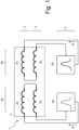
- Fig. 1 shows a schematic circuit diagram for an exemplary first embodiment of an inventive gradient coil system 1.
- the gradient coil system 1 comprises a main coil 2, here comprising two main sub-coils 2a, 2b. Further, the gradient coil system 1 comprises a shielding coil 3, here comprising two shielding sub-coils 3a, 3b. The main coil 2 and the shielding coil 3 together can be considered as a gradient coil 5. Even further, the gradient coil system 1 comprises a power supply system 4, here comprising two independent power supply units 4a, 4b.
- Sub-coil group 6a comprises the main sub-coil 2a and the shielding sub-coil 3a electrically connected in series, and supplied with an electric current Ia by supply unit 4a.
- Sub-coil group 6b comprises the main sub-coil 2b and the shielding sub-coil 3b electrically connected in series, and supplied with an electric current Ib by supply unit 4b.
- the electric currents Ia and Ib may be set individually and independent from each other.
- the gradient coil 5 generates a gradient coil magnetic field Bz aligned with a z direction in a target volume about a center of the gradient coil 5, with the gradient coil magnetic field Bz varying along a gradient direction, here the z direction, and the shielding coil 3 radially surrounds the main coil 2 (not shown in Fig. 1 , but compare Fig. 3 top part). Since the main coil 2 or its main sub-coils 2a, 2b are shielded by shielding coil 3 or its shielding sub-coils 3a, 3b, in the outer surrounding of the gradient coil 5, the magnetic stray field is low.
- the sub-coil groups 6a, 6b are basically inductively decoupled.
- M 6a6b of the two sub-coil groups 6a, 6b further M 6a6b ⁇ 0.05 ⁇ L applies here, preferably with M 6a6b being practically zero.
- M 6a6b M 6b6a .
- the inductive decoupling can be accomplished by sufficient distance between the sub-coil groups 6a, 6b, in particular along the z direction.
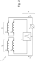
- Fig. 2 illustrates a schematic circuit diagram of a second embodiment of an inventive gradient coil system 1, similar to the one shown in Fig. 1 , so only the major differences are explained below.
- the power supply system 4 comprises a common power supply unit 7, providing all sub-coil groups 6a, 6b with electric currents Ia, Ib in parallel.
- the electric current Ia is directly supplied by and adjusted via the common power supply unit 7.
- the electric current Ib is adjusted (in addition to the adjustment at the common power supply unit 7) via a current adjustment unit 8.
- the current adjustment unit 8 may be designed as a variable resistor, for example.
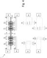
- Fig. 3 illustrates the first embodiment of Fig. 1 of the gradient coil system 1 in more detail in a geometric scheme (top) and a winding direction scheme (bottom).
- the windings of the main coil 2 are shown in thick lines
- the windings of the shielding coil 3 are shown in thin lines.
- each winding shown represents in practice one or more continuous windings (also applies to the following figures).
- the main sub-coil 2a consists of six windings connected in series (note that in the top part the windings are individually shown for simplification), all of which have a uniform winding direction (illustrated with arrow upwards in the bottom part).
- the winding direction corresponds to the electric current direction in the winding (clockwise or counter clockwise) when in each case looking in a fixedly defined way with respect to the coil axis (e.g. along the z axis in each case, or against the z axis in each case).
- the shielding sub-coil 3a consists here of six windings connected in series, all of which have a uniform winding direction (illustrated with arrow downwards in the bottom part).
- the axial position in z of the main sub-coil 2a and the shielding sub-coil 3a are basically the same.
- the main sub-coil 2b consists of six windings connected in series, all of which have a uniform winding direction (illustrated with arrow downwards in the bottom part).
- the shielding sub-coil 3b consists here of six windings connected in series, all of which have a uniform winding direction (illustrated with arrow upwards in the bottom part).
- the axial position in z of the main sub-coil 2b and the shielding sub-coil 3b are basically the same.
- the main sub-coils 2a, 2b have a uniform radius here, and the shielding sub-coils 3a, 3b have a uniform radius here.
- the radius of the shielding sub-coils 3a, 3b is larger than the radius of the main sub-coils, here about twice as large.
- the center 9 of the target volume 10 of the gradient coil system 1 is also the magnetic center of the gradient coil 5 altogether.
- the windings of the sub-coil groups 6a, 6b are arranged mirror-symmetric with respect to a mirror plane M perpendicular to the z axis and including the center point 9 (neglecting the electric supply lines and the winding directions).
- the target volume 10 is here basically cylindrical (with the cylinder axis along the z axis) and is somewhat elongated in the z direction, what is particularly useful for a sample in a vial or sample tube. Note that the target volume 10 may extend into the axial interior of the main sub-coils 2a, 2b.
- the sub-coils 2a, 3a of sub-coil group 6a are connected in series and receive power from power supply unit 4a via connecting cables 11, and sub-coils 2b, 3b of sub-coil group 6b are connected in series and receive power from power supply unit 4b via connecting cables 11.
- the connecting cables (supply lines) 11 lead from the sub-coil groups 6a, 6b to one axial side of the gradient coil 5 only, for example to the left axial side, for connecting to the power supply system or here its power supply units 6a, 6b, respectively, so the other axial side is free for a sample supply systems (not shown here, but compare Fig. 15 ).
- Fig. 4 illustrates a third embodiment of a gradient coil system 1, similar to the embodiment shown in Fig. 3 , so only the major differences are explained below.
- N The higher the number of individually powered sub-coil groups N, the higher the order of expansion components that can be adjusted or corrected in the gradient coil magnetic field.
- N 2 (as shown in Figs. 1-3 ), first order expansion components can be generated or corrected/adjusted.
- N 4 (as shown in Fig. 4 )
- third order expansion components can be generated or corrected/adjusted, and so on.
- Fig. 5a shows a fourth embodiment of an inventive gradient coil system 1 similar to the gradient coil system shown in Fig. 4 , wherein only the winding direction scheme is illustrated in Fig. 5a . Only the major differences are explained below.
- the winding direction in some sub-coils changes within the respective sub-coil.
- the majority of the windings (here the axial outer windings) has winding direction “upwards” in main sub-coil 2a and “downwards” in main-sub coil 2d
- the minority of windings (here the axial inner winding) has winding direction “downwards” in main sub-coil 2a and "upwards” in main sub-coil 2d.
- the winding direction is “downwards” and therefore uniform and opposite to the majority of windings of main sub-coil 2a.
- the winding direction is “upwards” and therefore uniform and opposite to the majority of windings of main sub-coil 2d.
- Such a setup may be useful in fine-tuning the gradient coil magnetic field in the target volume, in particular for minimizing higher order expansion components in the gradient coil magnetic field.
- Fig. 5b shows a variant of the fourth embodiment of an inventive gradient coil system 1 (see Fig. 5a ), similar to the gradient coil system shown in Fig. 5a . Only the major differences with respect to Fig. 5a are explained below. Only the winding direction scheme is illustrated in Fig. 5b .
- the winding direction in some sub-coils here in all main sub-coils 2a, 2b, 2c, 2d and in the axially inner shielding sub-coils 3b, 3c, changes within the respective sub-coil.
- the respective axially inner winding has an opposite winding direction as compared to the respective axially outer windings.
- Fig. 6 illustrates schematically a fifth embodiment of an inventive gradient coil system 1 in a geometric scheme, wherein the main coil 2 (top) and the shielding coil 3 (bottom) are shown separated for better understanding. Note that the main coil 2 and the shielding coil 3 are coaxial with respect to the z axis.
- the gradient coil system 1 comprises two sub-coil groups 6a (with sub-coils 2a, 3a) and 6b (with sub-coils 2b, 3b).
- main sub-coil 2b is most of its part mirror-symmetric to main sub-coil 2a with respect to mirror plane M, but main sub-coil 2b contains an additional winding package 12, for which there is no equivalent in main sub-coil 2a.
- shielding sub-coil 3a is most of its part mirror-symmetric to shielding sub-coil 3b with respect to mirror plane M, but shielding sub-coil 3a contains an additional winding 13, for which there is no equivalent in shielding sub-coil 3b.
- the sub-coil groups 6a, 6b are arranged asymmetric with respect to the mirror plane M (which runs perpendicular to the central z axis and cuts the center point of the gradient coil).
- Fig. 6 by way of example, there is also illustrated the measurement of a target volume profile of a gradient coil system 1 by inserting and moving a Hall probe 21, typically arranged on a holder 22, into the main coil 2 along the z axis.
- the gradient coil system 1 is operated with constant currents, and the gradient coil magnetic field is measured as a function of the z position.
- the pick-up loop 20 has a radius c larger than the (maximum) radius b of the gradient coil system 1, and the pick-up loop 20 is arranged in a plane perpendicular to the z axis.
- the gradient coil system 1 is operated with alternating currents, and an induced electric voltage in the pick-up loop 20 is measured as a function of the z position.
- Fig. 7 illustrates an exemplary diagram showing residual magnetic flux profiles (flux shown on the ordinate/upward axis) along the z direction (z position shown on the abscissa/rightward axis) of a typical gradient coil system in accordance with the invention, for example as shown in Fig. 1 .
- the residual magnetic flux is measured in a plane perpendicular to the z axis and within a radius c, which is larger than the (maximum) radius b of the gradient coil system, for example with a pick-up loop of radius c with an alternating current in the sub-coil groups (not shown, but compare Fig. 6 ).
- the diagram shows in full lines a desired residual profile 14a (or reference residual profile, "reference flux") which would result for an ideal gradient coil system, without manufacturing tolerances (and optionally also taking into account influence from an NMR probe or other magnet components), for which the influence of Eddy currents on the NMR measurement would be minimal.
- the desired residual profile 14a is typically calculated based on the overall design of the NMR probe.
- a measured residual profile 14b is obtained which is distorted with respect to the reference residual profile ("distorted flux").
- the measured residual profile 14b is shown with dotted lines; note that for most of it, it is overlaid by the reference residual profile 14a.
- the measured residual profile 14b deviates from an antisymmetric profile, and is therefore considered asymmetric.
- the measured residual profile 14b can be adjusted and brought close to the reference residual profile 14a, or the measured residual profile 14b can be made (approximately) anti-symmetric with respect to the center 9. Note that for this purpose, different current settings may be set and the residual profile 14b may be measured again, thus adjusting the measured residual profile 14b iteratively.
- a typical current difference between two sub-coil groups is typically up to 6%, preferably up to 4% with respect to the lower current, in order to achieve an antisymmetric measured residual profile.
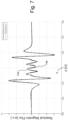
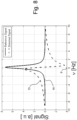
- Fig. 8 illustrates exemplary, typical NMR signals (obtained by fast Fourier transformation of free induction decay, with signal amplitude noted on the ordinate/upward axis, and frequency ⁇ noted to the abscissa/rightward axis) obtained with a distorted residual (flux) profile (see Fig. 7 ), compare the distorted signal 15 with the dashed lines, and a reference signal 16 obtained with the reference residual (flux) profile (see Fig. 7 ) shown with full lines.
- the distorted residual profile causes a phase artifact in NMR measurements, as can be seen in the measured distorted signal 15.
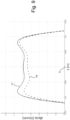
- the exemplary diagram of Fig. 9 shows profiles of the first derivative d Bz/dz (noted on the ordinate/upward axis) of the gradient coil magnetic field Bz as a function of the position along z (noted to the abscissa/rightward axis) in the target volume for a typical gradient coil system according to the invention, for example as shown in Fig. 1 .
- a reference target volume profile also called desired target volume profile 17 may be calculated.
- a measured target volume profile 18 in general deviates from the desired target volume profile 17, i.e. the measured target volume 18 profile is distorted with respect to the desired target volume profile 17.
- the measured target volume profile 18 can be adjusted and brought close to the desired target volume profile 17, or the measured target volume profile 18 can be (approximately) made symmetric with respect to the center 9. This improves the NMR measurement quality, in particular the resolution.
- a typical current difference between two sub-coil groups is typically up to 6%, preferably up to 4% with respect to the lower current, in order to achieve an symmetric target volume profile.
- Fig. 10 shows in a schematic perspective view a main gradient coil 2 for the present invention, for generating an x gradient of the gradient coil magnetic field Bz.
- the main gradient coil 2 comprises a first main sub-coil 2a (on the right side of the coil bobbin, with respect to the circumference), and a second main sub-coil 2b (on the left side of the coil bobbin, mostly covered).
- the main sub-coils 2a, 2b are arranged opposite to each other with respect to the x direction.
- the corresponding shielding coil may be designed analogously, but with a larger radius.
- Fig. 11 shows in a schematic perspective view a main gradient coil 2 for the present invention, for generating a y gradient of the gradient coil magnetic field Bz.
- the main gradient coil 2 comprises a first main sub-coil 2a (on the top side of the coil bobbin, with respect to the circumference), and a second main sub-coil 2b (on the bottom side of the coil bobbin, mostly covered).
- the main sub-coils 2a, 2b are arranged opposite to each other with respect to the y direction.
- the corresponding shielding coil may be designed analogously, but with a larger radius.
- Fig. 12 shows in a schematic perspective view a main gradient coil 2 for the present invention, for generating a z gradient of the gradient coil magnetic field Bz.
- the main gradient coil 2 comprises four main sub-coil 2a-2d, basically running circular about the bobbin each.
- the main sub-coils 2a-2d are arranged subsequently along the z axis.
- the corresponding shielding coil may be designed analogously, but with a larger radius.
- gradient coil systems as sketched in Figs. 10-12 may be radially nested (not shown). Further note that x, y, z form an orthogonal coordinate system.
- Fig. 13 shows in a schematic perspective view a main gradient coil 2 for the present invention, for generating an x gradient of the gradient coil magnetic field Bz, similar to the design shown in Fig. 10 . Only the major differences are explained.
- the main gradient coil 2 comprises a first main sub-coil 2a (on the left axial side of the coil bobbin), and a second main sub-coil 2b (on the right axial side of the coil bobbin).
- the main sub-coils 2a, 2b are arranged opposite to each other with respect to the z direction.
- the corresponding shielding coil may be designed analogously, but with a larger radius.
- Fig. 14 shows in a schematic perspective view a main gradient coil 2 for the present invention, for generating a y gradient of the gradient coil magnetic field Bz. similar to the design shown in Fig. 11 . Only the major differences are explained.
- the main gradient coil 2 comprises a first main sub-coil 2a (on the right axial side of the coil bobbin), and a second main sub-coil 2b (on the left axial side of the coil bobbin).
- the main sub-coils 2a, 2b are arranged opposite to each other with respect to the z direction.
- the corresponding shielding coil may be designed analogously, but with a larger radius.
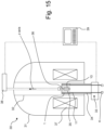
- Fig. 15 shows in a very schematic cross-section an NMR spectrometer 30 for the invention, comprising a cryostat 31 with a room temperature bore 32 running parallel to a z axis.
- the cryostat 31 contains a superconducting magnet 37, generating a background magnetic field B 0 along the z axis in a target volume 10 inside the bore 32.
- a gradient coil system 1 for generating (here) a gradient coil magnetic field varying along the z (and/or x, y) axis.
- the gradient coil system 1 is supplied with electric currents by a power supply system 4 via electric connecting cables 11, all of which lead downwards from the gradient coil system 1.
- the power supply system 4 here comprises two individual power supply units for powering two sub-coil groups.
- RF coil system RF transmitting and receiving system 35
- sample tube 36 containing a sample to be investigated.
- the RF coil system 35 is arranged radially within the gradient coil system 1, and the target volume 10 is within the RF coil system 35. At least part of the sample in the sample tube 36 is located in the target volume 10.
- the sample tube 36 may be changed with a sample robot 38, acting here from the top end of the bore 32.
- the sample robot 38 and the NMR probe 33 are controlled by a computer 39.
- the magnetic field in the surrounding outside the gradient coil system are called residual fields. These residual fields are calculated on a cylindric tube which is concentric to the gradient coil system.
- the radius of said tube is c, with c>b, and b being the outer radius of the shielding coil.
- j Grad ( ⁇ , ⁇ ,z,t ) is the current density of the gradient coil system. Since it is switched on and off, it is time dependent, with t: time. For simplification of notation, the location variables ( ⁇ , ⁇ ,z ) are replaced with x .
- V is the measuring volume
- ⁇ 0 4 ⁇ ⁇ ⁇ 10 -7 H/m is the permeability of vacuum.
- a ⁇ Soll , c is the desired vector potential, which is generated by non-vanishing outer residual fields.
- a ⁇ Soll , c is determined during the design of the gradient coil system and is generated by discretion of currents both in the main coil and in the shielding coil, and by the limited space in z direction. This vector potential is already optimized with respect to effects of induced Eddy currents on the NMR signal, flowing after switching of the current in the gradient coil system.
- a Ist,c is the actual vector potential on the same cylinder tube.
- the values m and k are azimuthal ( m ) and axial ( k ) wave numbers.
- the vectors e ⁇ and e z are the unit vectors in cylinder coordinates.
- the residual fields may be measured directly with a Hall sensor, or indirectly via the induced voltage in a pick-up loop.
- the example discussed here refers to a gradient coil system generating a z gradient. In good approximation, the residual field is rotationally symmetric with respect to the z axis. With an annular pick-up loop oriented coaxial to the gradient coil system and having the radius c larger than the outer radius of the shielding coil, the residual fields along the z axis may be recorded.
- the residual fields are described by the vector potential A Ist,c . Due to the selected geometry, only the ⁇ -component A ⁇ Ist , c is non-zero.
- the time dependent magnetic flux of the gradient coil system in z direction then is ⁇ S B z Ist , c z t ⁇ dS and induces a voltage V ind in the pick-up coil.
- the induced voltage can be measured in a simple way.
Landscapes
- Physics & Mathematics (AREA)
- Condensed Matter Physics & Semiconductors (AREA)
- General Physics & Mathematics (AREA)
- Health & Medical Sciences (AREA)
- Epidemiology (AREA)
- General Health & Medical Sciences (AREA)
- Nuclear Medicine, Radiotherapy & Molecular Imaging (AREA)
- Radiology & Medical Imaging (AREA)
- Engineering & Computer Science (AREA)
- Signal Processing (AREA)
- High Energy & Nuclear Physics (AREA)
- Magnetic Resonance Imaging Apparatus (AREA)
Priority Applications (2)
| Application Number | Priority Date | Filing Date | Title |
|---|---|---|---|
| EP22181052.6A EP4296702A1 (fr) | 2022-06-24 | 2022-06-24 | Système de bobines de gradient auto-blindées divisées doté d'un système d'alimentation permettant de régler individuellement les courants des groupes de sous-bobines |
| US18/339,802 US12366620B2 (en) | 2022-06-24 | 2023-06-22 | Split self-shielded gradient coil system, with power supply system for individually adjusting currents of sub-coil groups |
Applications Claiming Priority (1)
| Application Number | Priority Date | Filing Date | Title |
|---|---|---|---|
| EP22181052.6A EP4296702A1 (fr) | 2022-06-24 | 2022-06-24 | Système de bobines de gradient auto-blindées divisées doté d'un système d'alimentation permettant de régler individuellement les courants des groupes de sous-bobines |
Publications (1)
| Publication Number | Publication Date |
|---|---|
| EP4296702A1 true EP4296702A1 (fr) | 2023-12-27 |
Family
ID=82308218
Family Applications (1)
| Application Number | Title | Priority Date | Filing Date |
|---|---|---|---|
| EP22181052.6A Pending EP4296702A1 (fr) | 2022-06-24 | 2022-06-24 | Système de bobines de gradient auto-blindées divisées doté d'un système d'alimentation permettant de régler individuellement les courants des groupes de sous-bobines |
Country Status (2)
| Country | Link |
|---|---|
| US (1) | US12366620B2 (fr) |
| EP (1) | EP4296702A1 (fr) |
Citations (11)
| Publication number | Priority date | Publication date | Assignee | Title |
|---|---|---|---|---|
| JPH10179544A (ja) | 1996-12-20 | 1998-07-07 | Shimadzu Corp | Mr装置の傾斜磁場発生用コイル |
| US6313630B1 (en) | 1999-08-25 | 2001-11-06 | Ge Medical Systems Global Technology Company Llc | Modular gradient system for MRI system |
| US7230426B2 (en) | 2003-06-20 | 2007-06-12 | General Electric Company | Split-shield gradient coil with improved fringe-field |
| US20130299182A1 (en) | 2009-12-23 | 2013-11-14 | Bp Corporation North America, Inc. | Rigless Low Volume Pump System |
| CN104020429A (zh) | 2014-06-06 | 2014-09-03 | 南京工程学院 | 一种梯度线圈并联分层的布线结构和布线方法 |
| CN204009031U (zh) | 2014-06-03 | 2014-12-10 | 南京工程学院 | 一种有源屏蔽梯度线圈结构 |
| EP2910965A1 (fr) * | 2014-02-19 | 2015-08-26 | Albert-Ludwigs-Universität Freiburg | Système de commutation multicanaux pour bobines à gradient de matrice IRM |
| CN204649947U (zh) | 2015-06-10 | 2015-09-16 | 武汉中科波谱技术有限公司 | 一种核磁共振波谱仪梯度线圈 |
| US20160334480A1 (en) * | 2015-05-12 | 2016-11-17 | Albert-Ludwigs-Universitat Freiburg | Arrangement for modifying a main magnetic field and method for producing such an arrangement |
| CN107957565A (zh) | 2017-12-21 | 2018-04-24 | 武汉中科牛津波谱技术有限公司 | 一种核磁共振波谱仪自屏蔽梯度线圈及其设计方法 |
| CN114545312A (zh) * | 2022-04-22 | 2022-05-27 | 浙江浙大西投脑机智能科技有限公司 | 一种非线性梯度线圈及扫描方法 |
Family Cites Families (9)
| Publication number | Priority date | Publication date | Assignee | Title |
|---|---|---|---|---|
| US4617516A (en) * | 1983-09-06 | 1986-10-14 | General Electric Company | Axial magnetic field gradient coil suitable for use with NMR apparatus |
| US5663648A (en) * | 1995-03-17 | 1997-09-02 | British Technology Group Usa, Inc. | Gradient coils having increased performance and decreased power consumption for use in MR systems |
| JP3556052B2 (ja) * | 1995-07-27 | 2004-08-18 | 株式会社東芝 | 磁気共鳴イメージング装置 |
| ES2907993T3 (es) * | 2008-06-20 | 2022-04-27 | Irving Weinberg | Procedimiento para disminuir los efectos biológicos de los gradientes de campo magnético |
| JP5434106B2 (ja) | 2009-02-05 | 2014-03-05 | セイコーエプソン株式会社 | 流体吐出装置及びその制御方法 |
| CN103747727B (zh) * | 2011-09-05 | 2016-03-09 | 株式会社日立医疗器械 | 倾斜磁场线圈装置及其调整方法以及磁共振成像装置 |
| DE102012203343B8 (de) | 2012-03-02 | 2013-10-24 | Bruker Biospin Ag | Gradientenspulensystem mit Korrekturwicklungen und Verfahren zu deren Herstellung |
| CN204649944U (zh) | 2015-05-27 | 2015-09-16 | 上海辰光医疗科技股份有限公司 | 指关节射频线圈 |
| US11243283B1 (en) * | 2020-07-29 | 2022-02-08 | Synaptive Medical Inc. | System and method to improve performance of asymmetrical gradient coils by allowing a uniform offset field |
-
2022
- 2022-06-24 EP EP22181052.6A patent/EP4296702A1/fr active Pending
-
2023
- 2023-06-22 US US18/339,802 patent/US12366620B2/en active Active
Patent Citations (11)
| Publication number | Priority date | Publication date | Assignee | Title |
|---|---|---|---|---|
| JPH10179544A (ja) | 1996-12-20 | 1998-07-07 | Shimadzu Corp | Mr装置の傾斜磁場発生用コイル |
| US6313630B1 (en) | 1999-08-25 | 2001-11-06 | Ge Medical Systems Global Technology Company Llc | Modular gradient system for MRI system |
| US7230426B2 (en) | 2003-06-20 | 2007-06-12 | General Electric Company | Split-shield gradient coil with improved fringe-field |
| US20130299182A1 (en) | 2009-12-23 | 2013-11-14 | Bp Corporation North America, Inc. | Rigless Low Volume Pump System |
| EP2910965A1 (fr) * | 2014-02-19 | 2015-08-26 | Albert-Ludwigs-Universität Freiburg | Système de commutation multicanaux pour bobines à gradient de matrice IRM |
| CN204009031U (zh) | 2014-06-03 | 2014-12-10 | 南京工程学院 | 一种有源屏蔽梯度线圈结构 |
| CN104020429A (zh) | 2014-06-06 | 2014-09-03 | 南京工程学院 | 一种梯度线圈并联分层的布线结构和布线方法 |
| US20160334480A1 (en) * | 2015-05-12 | 2016-11-17 | Albert-Ludwigs-Universitat Freiburg | Arrangement for modifying a main magnetic field and method for producing such an arrangement |
| CN204649947U (zh) | 2015-06-10 | 2015-09-16 | 武汉中科波谱技术有限公司 | 一种核磁共振波谱仪梯度线圈 |
| CN107957565A (zh) | 2017-12-21 | 2018-04-24 | 武汉中科牛津波谱技术有限公司 | 一种核磁共振波谱仪自屏蔽梯度线圈及其设计方法 |
| CN114545312A (zh) * | 2022-04-22 | 2022-05-27 | 浙江浙大西投脑机智能科技有限公司 | 一种非线性梯度线圈及扫描方法 |
Non-Patent Citations (3)
| Title |
|---|
| CAVANAGH ET AL.: "Protein NMR spectroscopy -principles and practice", 2006, ACADEMIC PRESS, pages: 311 - 315 |
| SEBASTIAN LITTIN ET AL: "Development and implementation of an 84-channel matrix gradient coil : Matrix Gradient Coil", MAGNETIC RESONANCE IN MEDICINE, vol. 79, no. 2, 1 February 2018 (2018-02-01), US, pages 1181 - 1191, XP055698293, ISSN: 0740-3194, DOI: 10.1002/mrm.26700 * |
| T. PARELLA: "Pulsed field gradients: a new tool for routine NMR", MAGNETIC RESONANCE IN CHEMISTRY, vol. 36, no. 7, July 1998 (1998-07-01), pages 467 - 495, XP002607211 |
Also Published As
| Publication number | Publication date |
|---|---|
| US12366620B2 (en) | 2025-07-22 |
| US20230417849A1 (en) | 2023-12-28 |
Similar Documents
| Publication | Publication Date | Title |
|---|---|---|
| US8067938B2 (en) | Microcoil NMR detectors | |
| US9658303B2 (en) | Gradient coil with correction windings and method for production thereof | |
| US8106657B2 (en) | Apparatus for high-resolution NMR spectroscopy and/or imaging with an improved filling factor and RF field amplitude | |
| US5173661A (en) | Nuclear magnetic resonance spectrometer | |
| Jensen et al. | Reduction of pulsed gradient settling time in the superconducting magnet of a magnetic resonance instrument | |
| US4926125A (en) | Surface gradient assembly for high speed nuclear magnetic resonance imaging | |
| WO2008084110A1 (fr) | Procédé et appareil pour fournir un volume sensible pour une rmn simple face | |
| EP0389911B1 (fr) | Procédé et appareil de réduction dans un dispositif de résonance magnétique des changements du champ de base dus aux gradients de champ magnétique pulsés | |
| Bielecki et al. | Zero‐field NMR and NQR spectrometer | |
| CN108303661B (zh) | 磁共振发射信号的校正 | |
| EP1760481B1 (fr) | Système de shims en forme de matrice avec des bobines groupées | |
| EP2551693A1 (fr) | Spectromètre à résonance magnétique nucléaire et procédé de correction de champ magnétique | |
| US20080164878A1 (en) | Minimum Energy Shim Coils For Magnetic Resonance | |
| Chen et al. | Low-temperature magnetic resonance imaging with 2.8 μm isotropic resolution | |
| EP0154996B1 (fr) | Appareil de production d'images par résonance magnétique au moyen de bobines de correction réglables | |
| US6313634B1 (en) | Device and method to homogenize a magnetic field | |
| McDowell et al. | Operating nanoliter scale NMR microcoils in a 1 tesla field | |
| Van Bentum et al. | Strategies for solid-state NMR in high-field Bitter and hybrid magnets | |
| EP4296702A1 (fr) | Système de bobines de gradient auto-blindées divisées doté d'un système d'alimentation permettant de régler individuellement les courants des groupes de sous-bobines | |
| JP2008209213A (ja) | Rfコイル | |
| Andris et al. | Analysis of NMR signal for static magnetic field standard | |
| KR20010095775A (ko) | 높은 라디오주파수 자기장 균일도를 갖는 핵자기 공명또는 핵자기 영상 코일 | |
| WO2004029645A1 (fr) | Ensemble de production de champ magnetique et procede associe | |
| EP1910859A2 (fr) | Appareil et procede de spectroscopie et/ou imagerie rmn a facteur de remplissage et amplitude du champ rf ameliores |
Legal Events
| Date | Code | Title | Description |
|---|---|---|---|
| PUAI | Public reference made under article 153(3) epc to a published international application that has entered the european phase |
Free format text: ORIGINAL CODE: 0009012 |
|
| STAA | Information on the status of an ep patent application or granted ep patent |
Free format text: STATUS: REQUEST FOR EXAMINATION WAS MADE |
|
| 17P | Request for examination filed |
Effective date: 20230310 |
|
| AK | Designated contracting states |
Kind code of ref document: A1 Designated state(s): AL AT BE BG CH CY CZ DE DK EE ES FI FR GB GR HR HU IE IS IT LI LT LU LV MC MK MT NL NO PL PT RO RS SE SI SK SM TR |
|
| P01 | Opt-out of the competence of the unified patent court (upc) registered |
Effective date: 20240206 |
|
| STAA | Information on the status of an ep patent application or granted ep patent |
Free format text: STATUS: EXAMINATION IS IN PROGRESS |
|
| 17Q | First examination report despatched |
Effective date: 20240618 |
|
| 17Q | First examination report despatched |
Effective date: 20240625 |