EP4296728A1 - Feuille de diffusion de lumière, unité de rétroéclairage, dispositif d'affichage à cristaux liquides et équipement d'informations - Google Patents
Feuille de diffusion de lumière, unité de rétroéclairage, dispositif d'affichage à cristaux liquides et équipement d'informations Download PDFInfo
- Publication number
- EP4296728A1 EP4296728A1 EP22770922.7A EP22770922A EP4296728A1 EP 4296728 A1 EP4296728 A1 EP 4296728A1 EP 22770922 A EP22770922 A EP 22770922A EP 4296728 A1 EP4296728 A1 EP 4296728A1
- Authority
- EP
- European Patent Office
- Prior art keywords
- light diffusion
- light
- diffusion sheet
- liquid crystal
- backlight unit
- Prior art date
- Legal status (The legal status is an assumption and is not a legal conclusion. Google has not performed a legal analysis and makes no representation as to the accuracy of the status listed.)
- Granted
Links
Images



Classifications
-
- G—PHYSICS
- G02—OPTICS
- G02F—OPTICAL DEVICES OR ARRANGEMENTS FOR THE CONTROL OF LIGHT BY MODIFICATION OF THE OPTICAL PROPERTIES OF THE MEDIA OF THE ELEMENTS INVOLVED THEREIN; NON-LINEAR OPTICS; FREQUENCY-CHANGING OF LIGHT; OPTICAL LOGIC ELEMENTS; OPTICAL ANALOGUE/DIGITAL CONVERTERS
- G02F1/00—Devices or arrangements for the control of the intensity, colour, phase, polarisation or direction of light arriving from an independent light source, e.g. switching, gating or modulating; Non-linear optics
- G02F1/01—Devices or arrangements for the control of the intensity, colour, phase, polarisation or direction of light arriving from an independent light source, e.g. switching, gating or modulating; Non-linear optics for the control of the intensity, phase, polarisation or colour
- G02F1/13—Devices or arrangements for the control of the intensity, colour, phase, polarisation or direction of light arriving from an independent light source, e.g. switching, gating or modulating; Non-linear optics for the control of the intensity, phase, polarisation or colour based on liquid crystals, e.g. single liquid crystal display cells
- G02F1/133—Constructional arrangements; Operation of liquid crystal cells; Circuit arrangements
- G02F1/1333—Constructional arrangements; Manufacturing methods
- G02F1/1335—Structural association of cells with optical devices, e.g. polarisers or reflectors
- G02F1/1336—Illuminating devices
- G02F1/133602—Direct backlight
- G02F1/133606—Direct backlight including a specially adapted diffusing, scattering or light controlling members
- G02F1/133607—Direct backlight including a specially adapted diffusing, scattering or light controlling members the light controlling member including light directing or refracting elements, e.g. prisms or lenses
-
- G—PHYSICS
- G02—OPTICS
- G02B—OPTICAL ELEMENTS, SYSTEMS OR APPARATUS
- G02B5/00—Optical elements other than lenses
- G02B5/02—Diffusing elements; Afocal elements
- G02B5/0205—Diffusing elements; Afocal elements characterised by the diffusing properties
- G02B5/021—Diffusing elements; Afocal elements characterised by the diffusing properties the diffusion taking place at the element's surface, e.g. by means of surface roughening or microprismatic structures
- G02B5/0231—Diffusing elements; Afocal elements characterised by the diffusing properties the diffusion taking place at the element's surface, e.g. by means of surface roughening or microprismatic structures the surface having microprismatic or micropyramidal shape
-
- G—PHYSICS
- G02—OPTICS
- G02B—OPTICAL ELEMENTS, SYSTEMS OR APPARATUS
- G02B5/00—Optical elements other than lenses
- G02B5/02—Diffusing elements; Afocal elements
- G02B5/0205—Diffusing elements; Afocal elements characterised by the diffusing properties
- G02B5/021—Diffusing elements; Afocal elements characterised by the diffusing properties the diffusion taking place at the element's surface, e.g. by means of surface roughening or microprismatic structures
- G02B5/0215—Diffusing elements; Afocal elements characterised by the diffusing properties the diffusion taking place at the element's surface, e.g. by means of surface roughening or microprismatic structures the surface having a regular structure
-
- G—PHYSICS
- G02—OPTICS
- G02B—OPTICAL ELEMENTS, SYSTEMS OR APPARATUS
- G02B5/00—Optical elements other than lenses
- G02B5/02—Diffusing elements; Afocal elements
- G02B5/0273—Diffusing elements; Afocal elements characterized by the use
- G02B5/0278—Diffusing elements; Afocal elements characterized by the use used in transmission
-
- G—PHYSICS
- G02—OPTICS
- G02F—OPTICAL DEVICES OR ARRANGEMENTS FOR THE CONTROL OF LIGHT BY MODIFICATION OF THE OPTICAL PROPERTIES OF THE MEDIA OF THE ELEMENTS INVOLVED THEREIN; NON-LINEAR OPTICS; FREQUENCY-CHANGING OF LIGHT; OPTICAL LOGIC ELEMENTS; OPTICAL ANALOGUE/DIGITAL CONVERTERS
- G02F1/00—Devices or arrangements for the control of the intensity, colour, phase, polarisation or direction of light arriving from an independent light source, e.g. switching, gating or modulating; Non-linear optics
- G02F1/01—Devices or arrangements for the control of the intensity, colour, phase, polarisation or direction of light arriving from an independent light source, e.g. switching, gating or modulating; Non-linear optics for the control of the intensity, phase, polarisation or colour
- G02F1/13—Devices or arrangements for the control of the intensity, colour, phase, polarisation or direction of light arriving from an independent light source, e.g. switching, gating or modulating; Non-linear optics for the control of the intensity, phase, polarisation or colour based on liquid crystals, e.g. single liquid crystal display cells
- G02F1/133—Constructional arrangements; Operation of liquid crystal cells; Circuit arrangements
- G02F1/1333—Constructional arrangements; Manufacturing methods
- G02F1/1335—Structural association of cells with optical devices, e.g. polarisers or reflectors
- G02F1/133553—Reflecting elements
-
- G—PHYSICS
- G02—OPTICS
- G02F—OPTICAL DEVICES OR ARRANGEMENTS FOR THE CONTROL OF LIGHT BY MODIFICATION OF THE OPTICAL PROPERTIES OF THE MEDIA OF THE ELEMENTS INVOLVED THEREIN; NON-LINEAR OPTICS; FREQUENCY-CHANGING OF LIGHT; OPTICAL LOGIC ELEMENTS; OPTICAL ANALOGUE/DIGITAL CONVERTERS
- G02F1/00—Devices or arrangements for the control of the intensity, colour, phase, polarisation or direction of light arriving from an independent light source, e.g. switching, gating or modulating; Non-linear optics
- G02F1/01—Devices or arrangements for the control of the intensity, colour, phase, polarisation or direction of light arriving from an independent light source, e.g. switching, gating or modulating; Non-linear optics for the control of the intensity, phase, polarisation or colour
- G02F1/13—Devices or arrangements for the control of the intensity, colour, phase, polarisation or direction of light arriving from an independent light source, e.g. switching, gating or modulating; Non-linear optics for the control of the intensity, phase, polarisation or colour based on liquid crystals, e.g. single liquid crystal display cells
- G02F1/133—Constructional arrangements; Operation of liquid crystal cells; Circuit arrangements
- G02F1/1333—Constructional arrangements; Manufacturing methods
- G02F1/1335—Structural association of cells with optical devices, e.g. polarisers or reflectors
- G02F1/1336—Illuminating devices
- G02F1/133602—Direct backlight
- G02F1/133603—Direct backlight with LEDs
-
- G—PHYSICS
- G02—OPTICS
- G02F—OPTICAL DEVICES OR ARRANGEMENTS FOR THE CONTROL OF LIGHT BY MODIFICATION OF THE OPTICAL PROPERTIES OF THE MEDIA OF THE ELEMENTS INVOLVED THEREIN; NON-LINEAR OPTICS; FREQUENCY-CHANGING OF LIGHT; OPTICAL LOGIC ELEMENTS; OPTICAL ANALOGUE/DIGITAL CONVERTERS
- G02F1/00—Devices or arrangements for the control of the intensity, colour, phase, polarisation or direction of light arriving from an independent light source, e.g. switching, gating or modulating; Non-linear optics
- G02F1/01—Devices or arrangements for the control of the intensity, colour, phase, polarisation or direction of light arriving from an independent light source, e.g. switching, gating or modulating; Non-linear optics for the control of the intensity, phase, polarisation or colour
- G02F1/13—Devices or arrangements for the control of the intensity, colour, phase, polarisation or direction of light arriving from an independent light source, e.g. switching, gating or modulating; Non-linear optics for the control of the intensity, phase, polarisation or colour based on liquid crystals, e.g. single liquid crystal display cells
- G02F1/133—Constructional arrangements; Operation of liquid crystal cells; Circuit arrangements
- G02F1/1333—Constructional arrangements; Manufacturing methods
- G02F1/1335—Structural association of cells with optical devices, e.g. polarisers or reflectors
- G02F1/1336—Illuminating devices
- G02F1/133602—Direct backlight
- G02F1/133605—Direct backlight including specially adapted reflectors
-
- G—PHYSICS
- G02—OPTICS
- G02F—OPTICAL DEVICES OR ARRANGEMENTS FOR THE CONTROL OF LIGHT BY MODIFICATION OF THE OPTICAL PROPERTIES OF THE MEDIA OF THE ELEMENTS INVOLVED THEREIN; NON-LINEAR OPTICS; FREQUENCY-CHANGING OF LIGHT; OPTICAL LOGIC ELEMENTS; OPTICAL ANALOGUE/DIGITAL CONVERTERS
- G02F1/00—Devices or arrangements for the control of the intensity, colour, phase, polarisation or direction of light arriving from an independent light source, e.g. switching, gating or modulating; Non-linear optics
- G02F1/01—Devices or arrangements for the control of the intensity, colour, phase, polarisation or direction of light arriving from an independent light source, e.g. switching, gating or modulating; Non-linear optics for the control of the intensity, phase, polarisation or colour
- G02F1/13—Devices or arrangements for the control of the intensity, colour, phase, polarisation or direction of light arriving from an independent light source, e.g. switching, gating or modulating; Non-linear optics for the control of the intensity, phase, polarisation or colour based on liquid crystals, e.g. single liquid crystal display cells
- G02F1/133—Constructional arrangements; Operation of liquid crystal cells; Circuit arrangements
- G02F1/1333—Constructional arrangements; Manufacturing methods
- G02F1/1335—Structural association of cells with optical devices, e.g. polarisers or reflectors
- G02F1/1336—Illuminating devices
- G02F1/133602—Direct backlight
- G02F1/133606—Direct backlight including a specially adapted diffusing, scattering or light controlling members
-
- G—PHYSICS
- G02—OPTICS
- G02F—OPTICAL DEVICES OR ARRANGEMENTS FOR THE CONTROL OF LIGHT BY MODIFICATION OF THE OPTICAL PROPERTIES OF THE MEDIA OF THE ELEMENTS INVOLVED THEREIN; NON-LINEAR OPTICS; FREQUENCY-CHANGING OF LIGHT; OPTICAL LOGIC ELEMENTS; OPTICAL ANALOGUE/DIGITAL CONVERTERS
- G02F1/00—Devices or arrangements for the control of the intensity, colour, phase, polarisation or direction of light arriving from an independent light source, e.g. switching, gating or modulating; Non-linear optics
- G02F1/01—Devices or arrangements for the control of the intensity, colour, phase, polarisation or direction of light arriving from an independent light source, e.g. switching, gating or modulating; Non-linear optics for the control of the intensity, phase, polarisation or colour
- G02F1/13—Devices or arrangements for the control of the intensity, colour, phase, polarisation or direction of light arriving from an independent light source, e.g. switching, gating or modulating; Non-linear optics for the control of the intensity, phase, polarisation or colour based on liquid crystals, e.g. single liquid crystal display cells
- G02F1/133—Constructional arrangements; Operation of liquid crystal cells; Circuit arrangements
- G02F1/1333—Constructional arrangements; Manufacturing methods
- G02F1/1335—Structural association of cells with optical devices, e.g. polarisers or reflectors
- G02F1/1336—Illuminating devices
- G02F1/133602—Direct backlight
- G02F1/133611—Direct backlight including means for improving the brightness uniformity
Definitions
- the present disclosure relates to a light diffusion sheet, a backlight unit, a liquid crystal display device, and information equipment.
- Liquid crystal display devices have been widely used as display devices for various types of information equipment such as smartphones and tablet terminals in recent years.
- As backlights of liquid crystal displays a direct-lit type in which light sources are disposed at the rear of a liquid crystal panel or an edge-lit type in which light sources are disposed near side surfaces of a liquid crystal panel has been mainly employed.
- a light diffusion sheet is used to increase and uniformity of luminance and chromaticity over the entire screen by diffusing light from light sources such as light emitting diodes (LEDs) (see, for example, Patent Document 1).
- LEDs light emitting diodes
- a light diffusion sheet diffuses light incident from a light incident surface by utilizing diffusion caused by an uneven shape on a light emission surface or diffusion caused by dispersion, in a sheet base material, of fine particles having a refractive index different from the base material.
- a thin display of a device such as a laptop computer or a tablet terminal uses a light diffusion sheet in which a light emission surface has inverted pyramidal recesses and a light incident surface is embossed.
- a first light diffusion sheet is a light diffusion sheet including: a first surface as a light emission surface; and a second surface as a light incident surface, wherein the first surface includes a plurality of recesses each having an approximately inverted polygonal pyramid shape, the second surface is a flat surface with an arithmetic mean roughness of 0.1 ⁇ m or less, and an internal haze of the light diffusion sheet is 1.5% or less.
- the second surface as the light incident surface is a flat surface and an internal haze of the light diffusion sheet is 1.5% or less, light incident from the second surface reaches the first surface as an uneven surface substantially without being diffused in the sheet.
- high-luminance light that has traveled straight from the light sources toward the light diffusion sheet can be uniformly diffused by the recesses on the first surface, and thus, an image of the light sources is canceled and in-plane luminance uniformity can be enhanced.
- a second light diffusion sheet is a light diffusion sheet including: a first surface as a light emission surface; and a second surface as a light incident surface, wherein the first surface includes a plurality of recesses each having an approximately inverted polygonal pyramid shape, the second surface has an arithmetic mean roughness of 1.0 ⁇ m or more and 3.0 ⁇ m or less, and an internal haze of the light diffusion sheet is 1.5% or less.
- the second surface as the light incident surface has an arithmetic mean roughness of 3.0 ⁇ m or less and the internal haze of the light diffusion sheet is 1.5% or less, light incident from the second surface reaches the first surface as an uneven surface substantially without diffusing in the sheet.
- high-luminance light that has traveled straight from the light sources toward the light diffusion sheet can be uniformly diffused by the recesses on the first surface, and thus, an image of the light sources is canceled and in-plane luminance uniformity can be enhanced.
- the arithmetic mean roughness of the second surface as the light incident surface is 1.0 ⁇ m or more, degradation of luminance can be reduced. As a result, it is possible to achieve further reduction of thickness and reduction of the number of light sources.
- each of the recesses may have an approximately inverted quadrangular pyramid shape. In this case, light that has traveled straight from the light sources can be uniformly diffused by the first surface.
- each of the plurality of recesses may have an apical angle of 80° or more and 100° or less. In this case, light that has traveled straight from the light sources can be uniformly diffused by the first surface.
- a backlight unit is a backlight unit incorporated in a liquid crystal display device and configured to guide light from a plurality of light sources toward a display screen, the backlight unit and includes: the first or second light diffusion sheet according to the present disclosure located between the display screen and the plurality of light sources, wherein the first or second light diffusion sheet is disposed with the second surface facing the plurality of light sources.
- the backlight unit according to the present disclosure includes the first or second light diffusion sheet according to the present disclosure, in-plane luminance uniformity can be enhanced. Accordingly, it is possible to achieve further reduction of thickness and reduction of the number of light sources.
- the plurality of light sources may be disposed on a reflective sheet located at a side opposite to the display screen with respect to the light diffusion sheet.
- light is further diffused by multiple reflection between the light diffusion sheet and the reflective sheet so that in-plane luminance uniformity can be thereby further enhanced.
- the light diffusion sheet may include a plurality of the light diffusion sheets that are disposed between the display screen and the plurality of light sources. In this case, light that has traveled straight from the light sources is repeatedly diffused by the first surface of each of the light diffusion sheets so that in-plane luminance uniformity can be thereby further enhanced.
- a distance between the plurality of light sources and the light diffusion sheet may be 10 mm or less.
- diffusion property of the light diffusion sheet according to the present disclosure can suppress degradation of in-plane luminance uniformity.
- a liquid crystal display device includes: the backlight unit according to the present disclosure described above; and a liquid crystal display panel.
- liquid crystal display device includes the backlight unit according to the present disclosure, in-plane luminance uniformity can be enhanced. Thus, it is possible to achieve further reduction of thickness and reduction of the number of light sources.
- Information equipment includes the liquid crystal display device according to the present disclosure described above.
- a light diffusion sheet capable of increasing in-plane luminance uniformity can be provided.
- FIG. 1 is an example of a cross-sectional view of a liquid crystal display device according to this embodiment.
- FIG. 2 is an example of a cross-sectional view of a backlight unit according to this embodiment.
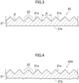
- FIG. 3 is an example of a cross-sectional view of a light diffusion sheet according to this embodiment.
- liquid crystal display device 50 in each sub-pixel corresponding to a pixel electrode, an alignment state of the liquid crystal layer 3 is changed by applying a predetermined voltage to the liquid crystal layer 3. Accordingly, transmittance of light incident from the backlight unit 40 through the first polarizing plate 6 is adjusted. The light whose transmittance has been adjusted is emitted through the second polarizing plate 7 so that an image is displayed.
- the liquid crystal display device 50 is used as a display device to be incorporated in various types of information equipment (e.g., an onboard device such as a car navigation system, a personal computer, a cellular phone, a portable information terminal, a portable game machine, a copying machine, a ticket machine, or an automatic teller machine).
- information equipment e.g., an onboard device such as a car navigation system, a personal computer, a cellular phone, a portable information terminal, a portable game machine, a copying machine, a ticket machine, or an automatic teller machine.
- the TFT substrate 1 includes, for example, a plurality of TFTs arranged in a matrix on a glass substrate, an interlayer insulating film covering the TFTs, a plurality of pixel electrodes arranged in a matrix on the interlayer insulating film and individually connected to the TFTs, and an alignment film covering the pixel electrodes.
- the CF substrate 2 includes, for example, a black matrix disposed on the glass substrate and having a lattice pattern, color filters including a red layer, a green layer, and a blue layer disposed between the gratings of the black matrix, a common electrode covering the black matrix and the color filters, and an alignment film covering the common electrode.
- the liquid crystal layer 3 is made of, for example, a nematic liquid crystal material including liquid crystal molecules with electrooptic properties.
- Each of the first polarizing plate 6 and the second polarizing plate 7 includes, for example, a polarizer layer having a polarization axis in one direction, and a pair of protective layers sandwiching the polarizer layer.
- the backlight unit 40 includes a reflective sheet 41, a plurality of light sources 42 arranged in two dimensions on the reflective sheet 41, a light diffusion sheet 43 disposed above the light sources 42, a first prism sheet 44 and a second prism sheet 45 stacked in this order above the light diffusion sheet 43, and a polarizing sheet 46 disposed above the second prism sheet 45.
- the light diffusion sheet 43 may be used as a single layer, or three or more layers of the light diffusion sheets 43 may be used.
- the light sources 42 may be, for example, an LED device or a laser device, and an LED device may be used from the viewpoint of costs, productivity, and other reasons.
- Each of the light sources 42 may be rectangular in plan view.
- the length of one side may be 10 ⁇ m or more (preferably 50 ⁇ m or more) and 20 mm or less (preferably 10 mm or less, more preferably 5 mm or less).
- a plurality of LED chips may be arranged at regular intervals on the reflective sheet 41.
- the LEDs may be equipped with lenses.
- the light diffusion sheet 43 includes a base material layer 21.
- the base material layer 21 uses clear polycarbonate as a base material (matrix resin), for example.
- the base material layer 21 contains substantially no diffusion agent.
- the light diffusion sheet 43 (base material layer 21) includes a first surface 21a serving as a light emission surface and a second surface 21b serving as a light incident surface. That is, the light diffusion sheet 43 is oriented with the second surface 21b facing the light sources 42.
- a plurality of recesses 22 each having an approximately inverted polygonal pyramid shape, for example, an approximately inverted quadrangular pyramid shape (inverted pyramid shape) are arranged in two dimensions.
- the second surface 21b of the light diffusion sheet 43 has an arithmetic mean roughness of 3.0 ⁇ m or less.
- the light diffusion sheet 43 has a single-layer structure of the base material layer 21 in which the first surface 21a has an uneven shape (recesses 22).
- the light diffusion sheet 43 may have a double-layer structure including a base material layer having flat surfaces and a layer having an uneven shape at one surface, or may have a structure of three of more layers including a layer having an uneven shape at one surface.
- the inverted pyramidal (approximately inverted quadrangular pyramidal) recesses 22 are arranged in two dimensions so that the first surface 21a has an uneven shape in this embodiment, the recesses 22 may have other approximately inverted polygonal pyramid shapes, and/or the recesses 22 may be arranged at random not to impair advantages of the present disclosure.
- the term “approximately inverted polygonal pyramid/pyramidal” in consideration of difficulty in forming geometrically strict inverted polygonal pyramidal recesses by a normal shape transfer technique, the term “approximately inverted polygonal pyramid/pyramidal” is used, but the “approximately inverted polygonal pyramid/pyramidal” includes a true inverted polygonal pyramid and a shape that can be substantially regarded as an inverted polygonal pyramid.
- the term “approximately” means that approximation is possible.
- an “approximately inverted quadrangular pyramid” refers to a shape that can be approximated to an inverted quadrangular pyramid.
- the "approximately inverted polygonal pyramid” also includes an "inverted truncated polygonal pyramid” with a flat top whose area is small to such an extent that the advantages of the present disclosure are not lost.
- the "approximately inverted polygonal pyramid” also includes a shape deformed from an "inverted polygonal pyramid” within a range of unavoidable shape variation caused by processing accuracy in industrial production.
- Each of the first prism sheet 44 and the second prism sheet 45 is a film formed such that a plurality of grooves each having an isosceles triangle shape in a cross section are arranged adjacent to one another and an apical angle of a prism sandwiched between a pair of adjacent grooves is about 90°.
- the grooves formed on the first prism sheet 44 are perpendicular to the grooves formed on the second prism sheet 45.
- the first prism sheet 44 and the second prism sheet 45 may be integrated.
- Each of the first prism sheet 44 and the second prism sheet 45 may be a polyethylene terephthalate (PET) film having a prism shape by using an UV setting acrylic resin.
- PET polyethylene terephthalate
- the polarizing sheet 46 may be, for example, a sheet of a DBEF series manufactured by 3M Corporation.
- the polarizing sheet 46 enhances luminance of the display screen 50a by preventing absorption of light emitted from the backlight unit 40 in the first polarizing plate 6 of the liquid crystal display device 50.
- the first surface 21a as a light emission surface has the plurality of recesses 22 each having an approximately inverted polygonal pyramid shape
- the second surface 21b as a light incident surface has an arithmetic mean roughness of 3.0 ⁇ m or less
- an internal haze of the light diffusion sheet is 1.5% or less.
- the arithmetic mean roughness of the second surface 21b of the light diffusion sheet 43 is preferably 0.1 ⁇ m or more, more preferably 0.5 ⁇ m or more, even more preferably 1.0 ⁇ m or more.
- each of the recesses 22 has an approximately inverted quadrangular pyramid shape, light that has traveled straight from the light sources 42 can be uniformly diffused by the first surface 21a.
- the light sources 42 may be disposed on the reflective sheet 41 located at the side opposite to the display screen 50a with respect to the light diffusion sheet 43. In this case, light is further diffused by multiple reflection between the light diffusion sheet 43 and the reflective sheet 41 so that in-plane luminance uniformity can be thereby further enhanced.
- the light diffusion sheet 43 may include a plurality of the light diffusion sheets 43 that are disposed between the display screen 50a and the light sources 42. In this case, light that has traveled straight from the light sources 42 is repeatedly diffused by the first surface 21a of each of the light diffusion sheets 43 so that in-plane luminance uniformity can be thereby further enhanced.
- the liquid crystal display device 50 according to this embodiment includes the backlight unit 40 according to this embodiment and the liquid crystal display panel 5.
- in-plane luminance uniformity can be enhanced by the backlight unit 40 so that it is possible to achieve further reduction of thickness and reduction of the number of light sources.
- Similar advantages can also be obtained in information equipment (e.g., a personal computer or a cellular phone) in which the liquid crystal display device 50 according to this embodiment is incorporated.
- the light diffusion sheet 43 (base material layer 21) may be a diffusion agent or other additives as long as advantages of the present disclosure are not lost.
- the additives that can be contained include, but not limited to, inorganic particles of, for example, silica, titanium oxide, aluminium hydroxide, and barium sulfate, and organic particles of, for example, acrylic, acrylonitrile, silicone, polystyrene, and polyamide.
- a resin as a matrix of the base material layer 21 is not particularly limited as long as the resin is made of a light transmitting material, and the resin may be acrylic, polystyrene, polycarbonate, methyl methacrylate-styrene copolymer (MS) resin, polyethylene terephthalate, polyethylene naphthalate, cellulose acetate, or polyimide, for example.
- MS methyl methacrylate-styrene copolymer
- the thickness of the light diffusion sheet 43 is not particularly limited, and may be, for example, 3 mm or less (preferably 2 mm or less, more preferably 1.5 mm or less, even more preferably 1 mm or less), and 0.1 mm or more. If the thickness of the light diffusion sheet 43 exceeds 3 mm, it is difficult to achieve thickness reduction of a liquid crystal display. On the other hand, if the thickness of the light diffusion sheet 43 is less than 0.1 mm, it is difficult to obtain the effect of enhancing luminance uniformity described above.
- the light diffusion sheet 43 may have a film shape or a plate shape.
- the method for producing the light diffusion sheet 43 is not particularly limited and may be, for example, extrusion molding or injection molding.
- plastic particles in pellet form (that may be supplemented with a diffusion agent) is placed in a single-screw extruder, and melted and kneaded while being heated. Thereafter, the melted resin extruded by a T-die is cooled while being sandwiched between two metal rolls, and then conveyed with guide rolls and cut into a flat sheet by a sheet cutter, thereby producing a light diffusion sheet.
- the melted resin is sandwiched with the metal rolls having a surface with an inverted shape of a desired uneven shape so that the inverted shape on the roll surface is thereby transferred to the resin.
- the desired uneven shape is formed on the surface of the light diffusion sheet.
- the shape transferred to the resin is not necessarily a shape on which the shape of the roll surface is 100% transferred, and thus, the shape of the roll surface may be designed by back calculation from the transfer degree.
- plastic particles in pellet form necessary for forming each layer is placed in each of two single-screw extruders, and then, a procedure similar to the procedure described above is performed on each layer, and resulting sheets are stacked.
- the light diffusion sheet 43 may be produced by shape transfer with ultraviolet (UV) rays in the following manner. First, a roll having an inverted shape of an uneven shape to be transferred is filled with an uncured UV curable resin, and a base material is pushed against the resin. Next, with the roll filled with the UV curable resin being united with a base material, UV rays are applied to cure the resin. Thereafter, a sheet to which the uneven shape is transferred with the resin is peeled off from the roll. Lastly, the sheet was irradiated with UV rays again so that the resin is completely cured, thereby producing a light diffusion sheet whose surface has an uneven shape.
- UV ultraviolet
- the backlight unit 40 a direct-lit backlight unit in which the light sources 42 are dispersed at the rear of the display screen 50a of the liquid crystal display device 50 is used.
- the distance between the light sources 42 and the light diffusion sheet 43 needs to be reduced.
- this distance is reduced, a phenomenon in which luminance of a portion of the display screen 50a located on a region between the dispersed light sources 42 is smaller than those of the other portion (luminance variation) tends to occur.
- the use of the light diffusion sheet 43 according to this embodiment is useful for reducing luminance variation.
- usefulness of the present disclosure is supposed to be more significant in a case where the distance between light sources and a light diffusion sheet is 15 mm or less, preferably 10 mm or less, more preferably 5 mm or less, even more preferably 2 mm or less, ultimately 0 mm.
- Examples and comparative examples used light diffusion sheets each using clear polycarbonate as a base material and having a thickness of 130 ⁇ m.
- a plurality of recesses each having an approximately inverted quadrangular pyramid (inverted pyramid) shape with an apical angle of 90° were arranged at a pitch of 100 ⁇ m in two dimensions on a first surface (light emission surface) of a light diffusion sheet.
- light diffusion sheets each having a second surface (light incident surface) processed to have an arithmetic mean roughness Ra of 3.4 ⁇ m were prepared.
- Table 1 shows evaluation results of luminance and in-plane luminance uniformity of the light diffusion sheets of the examples and the comparative examples.
- the luminance shown in Table 1 is relative luminance assuming that luminance (average) of a comparative example with the same number of stacks of the light diffusion sheets is one.
- FIG. 5 shows a relationship between surface roughness (arithmetic mean roughness) Ra and in-plane luminance uniformity of a light incident surface of the light diffusion sheet of each of Examples 1 through 8 and Comparative Examples 1 and 2.
- FIG. 6 shows a relationship between surface roughness (arithmetic mean roughness) Ra and luminance of the light incident surface of the light diffusion sheet of each of Examples 1 through 8 and Comparative Examples 1 and 2.
Landscapes
- Physics & Mathematics (AREA)
- Nonlinear Science (AREA)
- General Physics & Mathematics (AREA)
- Optics & Photonics (AREA)
- Mathematical Physics (AREA)
- Chemical & Material Sciences (AREA)
- Crystallography & Structural Chemistry (AREA)
- Optical Elements Other Than Lenses (AREA)
- Liquid Crystal (AREA)
- Devices For Indicating Variable Information By Combining Individual Elements (AREA)
- Planar Illumination Modules (AREA)
Applications Claiming Priority (3)
| Application Number | Priority Date | Filing Date | Title |
|---|---|---|---|
| JP2021045467A JP2022144447A (ja) | 2021-03-19 | 2021-03-19 | 光拡散シート、バックライトユニット、液晶表示装置及び情報機器 |
| JP2022015101A JP7732916B2 (ja) | 2022-02-02 | 2022-02-02 | バックライトユニット、液晶表示装置及び情報機器 |
| PCT/JP2022/004369 WO2022196162A1 (fr) | 2021-03-19 | 2022-02-04 | Feuille de diffusion de lumière, unité de rétroéclairage, dispositif d'affichage à cristaux liquides et équipement d'informations |
Publications (3)
| Publication Number | Publication Date |
|---|---|
| EP4296728A1 true EP4296728A1 (fr) | 2023-12-27 |
| EP4296728A4 EP4296728A4 (fr) | 2024-08-21 |
| EP4296728B1 EP4296728B1 (fr) | 2026-04-08 |
Family
ID=83322211
Family Applications (1)
| Application Number | Title | Priority Date | Filing Date |
|---|---|---|---|
| EP22770922.7A Active EP4296728B1 (fr) | 2021-03-19 | 2022-02-04 | Feuille de diffusion de lumière, unité de rétroéclairage, dispositif d'affichage à cristaux liquides et équipement d'informations |
Country Status (5)
| Country | Link |
|---|---|
| US (2) | US12510783B2 (fr) |
| EP (1) | EP4296728B1 (fr) |
| KR (1) | KR20230132875A (fr) |
| TW (1) | TWI799166B (fr) |
| WO (1) | WO2022196162A1 (fr) |
Families Citing this family (1)
| Publication number | Priority date | Publication date | Assignee | Title |
|---|---|---|---|---|
| KR20250174032A (ko) * | 2023-04-28 | 2025-12-11 | 케이와 인코포레이티드 | 광 확산 시트, 백라이트 유닛, 액정 표시 장치, 및 정보 기기 |
Family Cites Families (17)
| Publication number | Priority date | Publication date | Assignee | Title |
|---|---|---|---|---|
| JP4531290B2 (ja) | 2001-05-18 | 2010-08-25 | 大日本印刷株式会社 | 保護拡散フィルム、面光源装置及び液晶表示装置 |
| JP2008145499A (ja) | 2006-12-06 | 2008-06-26 | Toppan Printing Co Ltd | 防眩性光拡散部材 |
| JP2010015109A (ja) * | 2008-07-07 | 2010-01-21 | Sony Corp | 光学フィルムおよびその製造方法、防眩性偏光子、ならびに表示装置 |
| JP5569008B2 (ja) * | 2009-06-07 | 2014-08-13 | ソニー株式会社 | バックライトおよび液晶表示装置 |
| JP2011002742A (ja) | 2009-06-22 | 2011-01-06 | Goyo Paper Working Co Ltd | 拡散レンズシート積層体 |
| JP2011129277A (ja) | 2009-12-15 | 2011-06-30 | Toppan Printing Co Ltd | バックライトユニット及びディスプレイ装置 |
| JP2012114003A (ja) * | 2010-11-25 | 2012-06-14 | Nippon Shokubai Co Ltd | 光学部材、および該光学部材を用いた面状光源装置 |
| JP6065488B2 (ja) * | 2012-09-19 | 2017-01-25 | 沖電気工業株式会社 | 帯域拡張装置及び方法 |
| JP2014059524A (ja) | 2012-09-19 | 2014-04-03 | Toppan Printing Co Ltd | 透明性凹凸フィルム及びその製造方法、並びに透明性凹凸フィルムを備えたディスプレイ |
| KR20160062043A (ko) * | 2013-09-26 | 2016-06-01 | 다이니폰 인사츠 가부시키가이샤 | 프리즘 시트, 면 광원 장치, 영상원 유닛 및 액정 표시 장치 |
| JP6693116B2 (ja) | 2015-12-17 | 2020-05-13 | 日産化学株式会社 | 光散乱膜形成用組成物及び光散乱膜 |
| EP3522141B1 (fr) * | 2016-09-28 | 2021-04-21 | FUJIFILM Corporation | Corps d'affichage lenticulaire, procédé de formation d'image lenticulaire, procédé de fabrication de corps d'affichage lenticulaire et programme de formation d'image lenticulaire |
| KR102075998B1 (ko) * | 2017-05-29 | 2020-05-18 | 주식회사 엘엠에스 | 차폐부가 형성된 광전달유닛, 이를 이용한 백라이트모듈 및 광전달유닛의 제조방법 |
| WO2019167471A1 (fr) * | 2018-02-27 | 2019-09-06 | 株式会社カネカ | Composition de résine et dopant pour fabrication de film par procédé de coulage en solution |
| JP6886992B2 (ja) | 2018-03-30 | 2021-06-16 | 恵和株式会社 | 光拡散板積層体、バックライトユニット、及び液晶表示装置 |
| WO2020054096A1 (fr) * | 2018-09-11 | 2020-03-19 | ローム株式会社 | Dispositif de commande de del, dispositif d'éclairage et dispositif d'affichage embarqué |
| WO2021011410A1 (fr) * | 2019-07-12 | 2021-01-21 | Magic Leap, Inc. | Procédés et systèmes d'affichage en réalité augmentée avec champ de vision dynamique |
-
2022
- 2022-02-04 WO PCT/JP2022/004369 patent/WO2022196162A1/fr not_active Ceased
- 2022-02-04 EP EP22770922.7A patent/EP4296728B1/fr active Active
- 2022-02-04 KR KR1020237029715A patent/KR20230132875A/ko not_active Ceased
- 2022-03-04 TW TW111107885A patent/TWI799166B/zh active
-
2023
- 2023-09-14 US US18/467,174 patent/US12510783B2/en active Active
-
2025
- 2025-11-21 US US19/396,349 patent/US20260079365A1/en active Pending
Also Published As
| Publication number | Publication date |
|---|---|
| US20240012286A1 (en) | 2024-01-11 |
| EP4296728B1 (fr) | 2026-04-08 |
| US20260079365A1 (en) | 2026-03-19 |
| KR20230132875A (ko) | 2023-09-18 |
| TWI799166B (zh) | 2023-04-11 |
| TW202238234A (zh) | 2022-10-01 |
| US12510783B2 (en) | 2025-12-30 |
| WO2022196162A1 (fr) | 2022-09-22 |
| EP4296728A4 (fr) | 2024-08-21 |
Similar Documents
| Publication | Publication Date | Title |
|---|---|---|
| JP7509808B2 (ja) | 拡散シート、バックライトユニット、液晶表示装置及び情報機器 | |
| JP7506640B2 (ja) | 光学シート積層体、バックライトユニット、液晶表示装置、情報機器、及びバックライトユニットの製造方法 | |
| EP4246192B1 (fr) | Feuille de diffusion de lumière, unité de rétroéclairage, dispositif d'affichage à cristaux liquides, appareil d'information, et procédé de fabrication de feuille de diffusion de lumière | |
| KR102816327B1 (ko) | 광학 시트 적층체, 백라이트 유닛, 액정표시장치, 정보기기, 및 백라이트 유닛의 제조방법 | |
| JP7499741B2 (ja) | 光学シート積層体、バックライトユニット、液晶表示装置、情報機器、及びバックライトユニットの製造方法 | |
| US20260079365A1 (en) | Light diffusion sheet, backlight unit, liquid crystal display device, and information equipment | |
| JP7037624B2 (ja) | 光学シート、バックライトユニット、液晶表示装置及び情報機器 | |
| JP7509721B2 (ja) | 光学シート積層体、バックライトユニット、液晶表示装置、情報機器、及びバックライトユニットの製造方法 | |
| JP2025004222A (ja) | 光拡散シート積層体、バックライトユニット、液晶表示装置及び情報機器 | |
| JP7732916B2 (ja) | バックライトユニット、液晶表示装置及び情報機器 | |
| KR102879487B1 (ko) | 광학 시트 적층체, 백라이트 유닛, 액정표시장치, 정보기기, 및 백라이트 유닛의 제조방법 | |
| KR102893465B1 (ko) | 광 확산 시트, 백라이트 유닛, 액정 표시 장치, 및 정보 기기 | |
| KR102893441B1 (ko) | 광확산 시트, 백라이트 유닛, 액정표시장치, 정보기기, 및 백라이트 유닛의 제조방법 | |
| JP2024075290A (ja) | 光拡散シート、バックライトユニット、液晶表示装置、及び情報機器 | |
| WO2024147312A1 (fr) | Feuille de diffusion de lumière, unité de rétroéclairage, dispositif d'affichage à cristaux liquides et appareil d'informations |
Legal Events
| Date | Code | Title | Description |
|---|---|---|---|
| STAA | Information on the status of an ep patent application or granted ep patent |
Free format text: STATUS: THE INTERNATIONAL PUBLICATION HAS BEEN MADE |
|
| PUAI | Public reference made under article 153(3) epc to a published international application that has entered the european phase |
Free format text: ORIGINAL CODE: 0009012 |
|
| STAA | Information on the status of an ep patent application or granted ep patent |
Free format text: STATUS: REQUEST FOR EXAMINATION WAS MADE |
|
| 17P | Request for examination filed |
Effective date: 20230919 |
|
| AK | Designated contracting states |
Kind code of ref document: A1 Designated state(s): AL AT BE BG CH CY CZ DE DK EE ES FI FR GB GR HR HU IE IS IT LI LT LU LV MC MK MT NL NO PL PT RO RS SE SI SK SM TR |
|
| RAP3 | Party data changed (applicant data changed or rights of an application transferred) |
Owner name: KEIWA INCORPORATED |
|
| DAV | Request for validation of the european patent (deleted) | ||
| DAX | Request for extension of the european patent (deleted) | ||
| A4 | Supplementary search report drawn up and despatched |
Effective date: 20240722 |
|
| RIC1 | Information provided on ipc code assigned before grant |
Ipc: G02F 1/13357 20060101ALI20240716BHEP Ipc: G02F 1/1335 20060101ALI20240716BHEP Ipc: F21S 2/00 20160101ALI20240716BHEP Ipc: G02B 5/02 20060101AFI20240716BHEP |
|
| STAA | Information on the status of an ep patent application or granted ep patent |
Free format text: STATUS: EXAMINATION IS IN PROGRESS |
|
| 17Q | First examination report despatched |
Effective date: 20250213 |
|
| GRAP | Despatch of communication of intention to grant a patent |
Free format text: ORIGINAL CODE: EPIDOSNIGR1 |
|
| STAA | Information on the status of an ep patent application or granted ep patent |
Free format text: STATUS: GRANT OF PATENT IS INTENDED |
|
| INTG | Intention to grant announced |
Effective date: 20251222 |
|
| GRAS | Grant fee paid |
Free format text: ORIGINAL CODE: EPIDOSNIGR3 |
|
| GRAA | (expected) grant |
Free format text: ORIGINAL CODE: 0009210 |
|
| STAA | Information on the status of an ep patent application or granted ep patent |
Free format text: STATUS: THE PATENT HAS BEEN GRANTED |
|
| AK | Designated contracting states |
Kind code of ref document: B1 Designated state(s): AL AT BE BG CH CY CZ DE DK EE ES FI FR GB GR HR HU IE IS IT LI LT LU LV MC MK MT NL NO PL PT RO RS SE SI SK SM TR |
|
| P01 | Opt-out of the competence of the unified patent court (upc) registered |
Free format text: CASE NUMBER: UPC_APP_0008291_4296728/2026 Effective date: 20260227 |
|
| RAP3 | Party data changed (applicant data changed or rights of an application transferred) |
Owner name: KEIWA INCORPORATED |
|
| REG | Reference to a national code |
Ref country code: CH Ref legal event code: F10 Free format text: ST27 STATUS EVENT CODE: U-0-0-F10-F00 (AS PROVIDED BY THE NATIONAL OFFICE) Effective date: 20260408 Ref country code: GB Ref legal event code: FG4D |
|
| REG | Reference to a national code |
Ref country code: DE Ref legal event code: R096 Ref document number: 602022034143 Country of ref document: DE |