EP4297151A1 - Ailette de refroidissement, module de batterie, bloc-batterie et dispositif le comprenant - Google Patents
Ailette de refroidissement, module de batterie, bloc-batterie et dispositif le comprenant Download PDFInfo
- Publication number
- EP4297151A1 EP4297151A1 EP22833719.2A EP22833719A EP4297151A1 EP 4297151 A1 EP4297151 A1 EP 4297151A1 EP 22833719 A EP22833719 A EP 22833719A EP 4297151 A1 EP4297151 A1 EP 4297151A1
- Authority
- EP
- European Patent Office
- Prior art keywords
- battery
- cooling fin
- battery cell
- heat dissipation
- heat sink
- Prior art date
- Legal status (The legal status is an assumption and is not a legal conclusion. Google has not performed a legal analysis and makes no representation as to the accuracy of the status listed.)
- Withdrawn
Links
Images




Classifications
-
- H—ELECTRICITY
- H01—ELECTRIC ELEMENTS
- H01M—PROCESSES OR MEANS, e.g. BATTERIES, FOR THE DIRECT CONVERSION OF CHEMICAL ENERGY INTO ELECTRICAL ENERGY
- H01M10/00—Secondary cells; Manufacture thereof
- H01M10/60—Heating or cooling; Temperature control
- H01M10/65—Means for temperature control structurally associated with the cells
- H01M10/655—Solid structures for heat exchange or heat conduction
- H01M10/6551—Surfaces specially adapted for heat dissipation or radiation, e.g. fins or coatings
-
- H—ELECTRICITY
- H01—ELECTRIC ELEMENTS
- H01M—PROCESSES OR MEANS, e.g. BATTERIES, FOR THE DIRECT CONVERSION OF CHEMICAL ENERGY INTO ELECTRICAL ENERGY
- H01M10/00—Secondary cells; Manufacture thereof
- H01M10/60—Heating or cooling; Temperature control
- H01M10/61—Types of temperature control
- H01M10/613—Cooling or keeping cold
-
- H—ELECTRICITY
- H01—ELECTRIC ELEMENTS
- H01M—PROCESSES OR MEANS, e.g. BATTERIES, FOR THE DIRECT CONVERSION OF CHEMICAL ENERGY INTO ELECTRICAL ENERGY
- H01M10/00—Secondary cells; Manufacture thereof
- H01M10/60—Heating or cooling; Temperature control
- H01M10/64—Heating or cooling; Temperature control characterised by the shape of the cells
- H01M10/647—Prismatic or flat cells, e.g. pouch cells
-
- H—ELECTRICITY
- H01—ELECTRIC ELEMENTS
- H01M—PROCESSES OR MEANS, e.g. BATTERIES, FOR THE DIRECT CONVERSION OF CHEMICAL ENERGY INTO ELECTRICAL ENERGY
- H01M10/00—Secondary cells; Manufacture thereof
- H01M10/60—Heating or cooling; Temperature control
- H01M10/65—Means for temperature control structurally associated with the cells
- H01M10/655—Solid structures for heat exchange or heat conduction
- H01M10/6554—Rods or plates
- H01M10/6555—Rods or plates arranged between the cells
-
- H—ELECTRICITY
- H01—ELECTRIC ELEMENTS
- H01M—PROCESSES OR MEANS, e.g. BATTERIES, FOR THE DIRECT CONVERSION OF CHEMICAL ENERGY INTO ELECTRICAL ENERGY
- H01M10/00—Secondary cells; Manufacture thereof
- H01M10/60—Heating or cooling; Temperature control
- H01M10/65—Means for temperature control structurally associated with the cells
- H01M10/655—Solid structures for heat exchange or heat conduction
- H01M10/6556—Solid parts with flow channel passages or pipes for heat exchange
-
- H—ELECTRICITY
- H01—ELECTRIC ELEMENTS
- H01M—PROCESSES OR MEANS, e.g. BATTERIES, FOR THE DIRECT CONVERSION OF CHEMICAL ENERGY INTO ELECTRICAL ENERGY
- H01M50/00—Constructional details or processes of manufacture of the non-active parts of electrochemical cells other than fuel cells, e.g. hybrid cells
- H01M50/20—Mountings; Secondary casings or frames; Racks, modules or packs; Suspension devices; Shock absorbers; Transport or carrying devices; Holders
- H01M50/204—Racks, modules or packs for multiple batteries or multiple cells
- H01M50/207—Racks, modules or packs for multiple batteries or multiple cells characterised by their shape
- H01M50/209—Racks, modules or packs for multiple batteries or multiple cells characterised by their shape adapted for prismatic or rectangular cells
-
- H—ELECTRICITY
- H01—ELECTRIC ELEMENTS
- H01M—PROCESSES OR MEANS, e.g. BATTERIES, FOR THE DIRECT CONVERSION OF CHEMICAL ENERGY INTO ELECTRICAL ENERGY
- H01M50/00—Constructional details or processes of manufacture of the non-active parts of electrochemical cells other than fuel cells, e.g. hybrid cells
- H01M50/20—Mountings; Secondary casings or frames; Racks, modules or packs; Suspension devices; Shock absorbers; Transport or carrying devices; Holders
- H01M50/204—Racks, modules or packs for multiple batteries or multiple cells
- H01M50/207—Racks, modules or packs for multiple batteries or multiple cells characterised by their shape
- H01M50/211—Racks, modules or packs for multiple batteries or multiple cells characterised by their shape adapted for pouch cells
-
- H—ELECTRICITY
- H01—ELECTRIC ELEMENTS
- H01M—PROCESSES OR MEANS, e.g. BATTERIES, FOR THE DIRECT CONVERSION OF CHEMICAL ENERGY INTO ELECTRICAL ENERGY
- H01M50/00—Constructional details or processes of manufacture of the non-active parts of electrochemical cells other than fuel cells, e.g. hybrid cells
- H01M50/20—Mountings; Secondary casings or frames; Racks, modules or packs; Suspension devices; Shock absorbers; Transport or carrying devices; Holders
- H01M50/256—Carrying devices, e.g. belts
-
- H—ELECTRICITY
- H01—ELECTRIC ELEMENTS
- H01M—PROCESSES OR MEANS, e.g. BATTERIES, FOR THE DIRECT CONVERSION OF CHEMICAL ENERGY INTO ELECTRICAL ENERGY
- H01M50/00—Constructional details or processes of manufacture of the non-active parts of electrochemical cells other than fuel cells, e.g. hybrid cells
- H01M50/20—Mountings; Secondary casings or frames; Racks, modules or packs; Suspension devices; Shock absorbers; Transport or carrying devices; Holders
- H01M50/262—Mountings; Secondary casings or frames; Racks, modules or packs; Suspension devices; Shock absorbers; Transport or carrying devices; Holders with fastening means, e.g. locks
- H01M50/264—Mountings; Secondary casings or frames; Racks, modules or packs; Suspension devices; Shock absorbers; Transport or carrying devices; Holders with fastening means, e.g. locks for cells or batteries, e.g. straps, tie rods or peripheral frames
-
- Y—GENERAL TAGGING OF NEW TECHNOLOGICAL DEVELOPMENTS; GENERAL TAGGING OF CROSS-SECTIONAL TECHNOLOGIES SPANNING OVER SEVERAL SECTIONS OF THE IPC; TECHNICAL SUBJECTS COVERED BY FORMER USPC CROSS-REFERENCE ART COLLECTIONS [XRACs] AND DIGESTS
- Y02—TECHNOLOGIES OR APPLICATIONS FOR MITIGATION OR ADAPTATION AGAINST CLIMATE CHANGE
- Y02E—REDUCTION OF GREENHOUSE GAS [GHG] EMISSIONS, RELATED TO ENERGY GENERATION, TRANSMISSION OR DISTRIBUTION
- Y02E60/00—Enabling technologies; Technologies with a potential or indirect contribution to GHG emissions mitigation
- Y02E60/10—Energy storage using batteries
Definitions
- the present disclosure relates to a cooling fin, a battery module, and a device including the same.
- chargeable/dischargeable secondary batteries are used as a power source for an electric vehicle (EV), a hybrid electric vehicle (HEV), a plug-in hybrid electric vehicle (P-HEV) and the like, in an attempt to solve air pollution and the like caused by existing gasoline vehicles using fossil fuel. Therefore, there is a growing need for development of the secondary battery.
- EV electric vehicle
- HEV hybrid electric vehicle
- P-HEV plug-in hybrid electric vehicle
- the lithium secondary battery has come into the spotlight because they have advantages, for example, being freely charged and discharged, and having very low self-discharge rate and high energy density.
- a middle- or large-sized battery module in which a large number of battery cells are electrically connected is used. Since the middle or large-sized battery module is preferably manufactured so as to have as small a size and weight as possible, a prismatic battery, a pouch-shaped battery or the like, which can be stacked with high integration and has a small weight relative to capacity, is mainly used as a battery cell of the middle or large-sized battery module.
- a battery pack comprising: a battery module including a battery cell stack in which a plurality of battery cells are stacked, a pack frame for accommodating the battery module, and a heat sink located between the battery cell stack and the pack frame, wherein a cooling fin is arranged between the two battery cells adjacent to each other, wherein the cooling fin comprises a body part in contact with the battery cell, and an extension part extending to the upper side (z-axis) of the battery cell stack and located adjacent to the heat sink, and wherein the extension part has a bent part formed by bending in a direction different from the upper side (z-axis).
- the heat sink is located outside the battery module, and the extension part may make contact with the heat sink.
- the bent part formed in the extension part may have an L-shaped spring shape or an S-shaped spring shape.
- the bent part may be deformable according to a distance between the battery cell stack and the heat sink.
- the battery pack may further comprise a heat dissipation layer formed between the battery cell stack and the heat sink.
- the cooling fins are formed in two or more numbers, the two or more cooling fins are disposed at intervals from each other, and the heat dissipation layer may be formed in plural numbers so as to correspond to the two or more cooling fins, respectively.
- the heat dissipation layer may make contact with the extension part.
- the heat dissipation layer may be located closer to a second point, which is a terminal end of the extension part, than a first point at which the body part and the extension part make contact with each other.
- the heat dissipation layer may make contact with the extension part and the heat sink.
- the battery module may comprise a side plate in contact with the outermost battery cell of the battery cell stack.
- the side plate is configured as at least two side plates, the battery cell stack is disposed between the two side plates, and a relative positional relationship between the two side plates and the battery cell stack may be fixed by a holding strap.
- the holding strap comprises a hook formed at the terminal end in the longitudinal direction, and a hook groove corresponding to the hook may be formed in the side plate.
- a device comprising at least one battery pack described above.
- a cooling fin that forms a heat transfer path between a battery cell and a heat sink, wherein the cooling fin comprises a body part located in parallel with the battery cell, and an extension part extending from one end of the body part toward the heat sink, and wherein the extension part has a round shape that is curved to have a curvature.
- the extension part comprises a first point having a first curvature and a second point having a second curvature, and the first curvature and the second curvature may be different from each other.
- the extension part comprises a first point having a first slope and a second point having a second slope, and the first slope and the second slope may be different from each other.
- the absolute value of the first slope on the cross section of the extension part is smaller than the absolute value of the second slope, and the first point may be located farther from one end of the body part than the second point.
- the first point may be located closer to the heat sink than the second point.
- the second point may be in non-contact with the heat sink.
- the extension part may be deformable according to a distance between the battery cell and the heat sink.
- the extension parts are formed in plural numbers on one cooling fin.
- a heat dissipation layer is located between the battery cell stack in which the plurality of battery cells are stacked and the heat sink, and the extension part may make contact with the heat dissipation layer.
- the heat dissipation layer is formed in plural numbers, the extension part is formed in plural numbers in one cooling fin, and the plurality of heat dissipation layers may correspond to a plurality of extensions formed on one cooling fin, respectively.
- the heat dissipation layer may be disposed discontinuously in the stacking direction of the battery cell stack.
- the cooling fins are formed in two or more numbers, and the two or more cooling fins are disposed at intervals from each other, and the heat dissipation layer may be formed in plural numbers so as to correspond to the two or more cooling fins, respectively.
- the heat dissipation layer may make contact with the extension part and the heat sink.
- a battery module comprising at least one cooling fin described above.
- a battery pack comprising at least one cooling fin described above.
- the heat inside the battery pack can be effectively removed, and a cascading thermal runaway phenomenon can be prevented.
- the 'upper surface' or 'lower surface' as used herein is defined as meaning two surfaces facing each other on the z-axis of the member.
- planar when referred to as “planar”, it means when a target portion is viewed from the upper side, and when referred to as “cross-sectional”, it means when a target portion is viewed from the side of a cross section cut vertically.
- the cooling fin of the present embodiment can be provided between the battery cells in the battery pack or battery module, and may be for maintaining the temperature in the battery pack or battery module within an appropriate range by promoting heat dissipation of the battery cells.
- a heat sink can be located on the upper side of the battery cells, and the cooling fin can promote heat dissipation of the battery cells by transferring the heat of the battery cells to the heat sink.
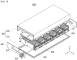
- a battery pack 1000 has at least one battery module 100, a pack frame 200 for accommodating the battery module 100, a resin layer 300 formed on the inner surface of the pack frame 200, an end plate 400 that closes the opened surface of the pack frame 200, a heat sink 500 disposed between the pack frame 200 and the battery cell stack 120, and a cooling fin 600 for dissipating heat from the battery cells 110 by making contact with the battery cells 110.
- the components contained in the battery pack 1000 are not limited thereto, and depending on the design, the battery pack 1000 may be provided in a state where some of the above-described components are omitted, and may be provided in a state in which other components not mentioned are added.
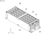
- the battery module 100 of the present embodiment may be provided in the form of a 'cell block' in which the module frame is omitted, and the battery cell stacks 120 contained in the cell block can be directly coupled to the pack frame 200 of the battery pack 1000.
- the structure of the battery pack 1000 can be simplified, advantages in terms of manufacturing cost and manufacturing process can be obtained, and the weight reduction of the battery pack can be achieved.
- the battery module 100 without a module frame may be referred to as a 'cell block' to distinguish it from a battery module having a module frame.
- the battery module 100 is a generic term having the battery cell stack 120 segmented into a predetermined unit for modularization regardless of the presence or absence of the module frame, and the battery module 100 should be construed as including both a typical battery module and a cell block having a module frame.
- Fig. 2 shows the battery module 100 provided in the form of a cell block, but the contents of these figures do not exclude the case of applying the battery module 100 of the sealed structure having the module frame to the battery pack 1000 of the present embodiment.
- the surface on which the outermost battery cell 110 is located may be referred to as a side surface of the battery cell stack 120, and in Figs. 1 and 2 , the side surface of the battery cell stack 120 is shown as two surfaces facing each other on the y-axis.
- the holding strap 140 may be provided with various materials or through various manufacturing methods.
- the holding strap 140 may be made from a material having elasticity, through which the volume change of the battery cell stack 120 due to swelling can be allowed within a certain range.
- the busbar frame 150 may include an electrically insulating material.
- the busbar frame 150 can restrict contact of the busbar with other portions of the battery cells 110 other than the portion joined to the electrode lead, and can prevent an electrical short circuit from occurring.
- the pack frame 200 may have various structures.
- the pack frame 200 may include a lower frame 210 and an upper frame 220.
- the lower frame 210 may be provided in a plate shape
- the upper frame 220 may be provided in a U-shape.
- At least one battery module 100 may be arranged in the plate-shaped lower frame 210, and a U-shaped upper frame 220 may be provided so as to wrap the upper surface of the module assembly and two surfaces on the x-axis.
- a resin layer 300 may be provided between the battery module 100 and the inner surface of the pack frame 200.
- the resin layer 300 may be provided between the bottom surface of the battery module 100 and the lower frame 210.
- the resin layer 300 can be provided between the upper surface of the battery module 100 and the upper frame 220.
- the resin layer 300 may be provided between the heat sink 500 and the upper frame 220 , which will be described later.
- the resin layer 300 may be formed by injecting a resin between one of the inner surfaces of the battery cell stack 120 and the pack frame 200. However, it is not necessarily the case, and the resin layer 300 may be a member provided in a plate shape.
- a groove 540 may be formed in the heat sink 500, through which the flow of cooling water can be determined.
- Fig. 3 is one example thereof, showing that the flow of cooling water is formed in a U-shape by the grooves 540 formed along the longitudinal direction of the heat sink 500.
- the above description is given on the assumption that the heat sink 500 is provided outside the battery module 100, but it is not necessarily the case, and the heat sink 500 can also be disposed inside the battery module 100.
- the heat sink 500 is disposed inside the battery module 100, even if the battery module 100 has a closed structure having a module frame, heat transfer between the heat sink 500 and the battery cells 110 can be easily achieved.
- the battery module 100 or the battery pack 1000 of the present embodiment may be provided with a cooling fin 600 for minimizing the deterioration in cooling efficiency due to the air gap.
- the cooling fins 600 of the present embodiment may be for maintaining the temperature inside the battery pack 1000 or the battery module 100 within an appropriate range.
- the cooling fin 600 may be provided between the battery cells 110 facing one surface thereof, and the cooling fins 600 can make contact with one surface of the battery cells 110 to thereby absorb heat generated from the battery cells 110.
- the cooling fins 600 may transfer heat absorbed from the battery cells 110 toward the heat sink 500.
- a part of the cooling fin 600 may exist in a separation space between the battery cell 110 and the heat sink 500, whereby the heat of the battery cell 110 may be transferred to the heat sink 500 via the cooling fin 600.
- the cooling fin 600 exists in the separation space between the battery cell 110 and the heat sink 500, the amount of heat dissipation interface material used in the battery module 100 or the battery pack 1000 can be minimized, and a reduction in manufacturing cost or simplification of the manufacturing process of the battery module 100 or the battery pack 1000 can be achieved.
- the cooling fin 600 may include a body part 610 in surface contact with one surface of the battery cell 110, and an extension part 620 extending beyond the upper surface of the battery cell stack 120 and located adjacent to the heat sink 500.
- the body part 610 receives transfer of heat from the battery cell 110 by making contact with the battery cell 110, and the extension part 620 can dissipate heat transferred toward the heat sink 500 by being located adjacent to the heat sink 500.
- the extension part 620 of the cooling fin 600 may be located adjacent to the lower plate 520 of the heat sink 500 or located so as to make contact with the lower plate 520.
- a plurality of cooling fins 600 may be provided in the battery cell stack 120.
- the cooling fins 600 may be provided between two adjacent battery cells 110, but it is not necessarily the case, and it may be provided only in some of the two adjacent battery cells 110. At this time, when the cooling fin 600 is provided only in some of the two adjacent battery cells 110, the cooling fins 600 may be preferably disposed at regular intervals so that the effect of the cooling fins 600 appears evenly on the battery cell stack 120.
- the cooling fin 600 may be made from a material having high thermal conductivity.
- the cooling fin 600 may be made from aluminum, gold, silver, copper, platinum, an alloy containing them, or the like.
- the cooling fin 600 made of a material with high thermal conductivity may have a very low thermal resistance than air, and heat may be more smoothly moved between the battery cell 110 and the heat sink 500 by the cooling fins 600.
- the cooling fin 600 of the present embodiment may have an elastic structure.
- the extension part 620 of the cooling fin 600 may be provided in the form of a spring having a bend.
- the extension part 620 may have a bent part formed by bending in a direction different from the upper side (z-axis) of the battery cell stack 120.
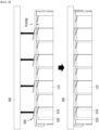
- the extension part 620 of the cooling fin 600 is extended to the outside of the battery cell stack 120 along the z-axis direction, as shown in Fig. 4 , but may be folded or bent so that the extension direction has an x-axis or a y-axis component.
- the absolute length of the cooling fin 600 existing in the separation space between the battery cell 110 and the heat sink 500 may be longer.
- the cooling fins 600 further traverse the space within the air gap, so that a decrease in cooling performance due to an air gap between the battery cell 110 and the heat sink 500 can be minimized.
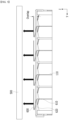
- the extension part 620 of the cooling fin 600 may be folded or bent twice or more so as to have an x-axis or y-axis component, as shown in Fig. 5 .
- the absolute length of the cooling fins 600 existing in the separation space between the battery cell 110 and the heat sink 500 may be longer in Fig. 5 than in Fig. 4 .
- the cooling fin 600 of Fig. 5 may exist more in the air gap space between the battery cell 110 and the heat sink 500. Therefore, as the number of bends or the bent length section of the cooling fin 600 increases, the effect of the cooling fin 600 can be further maximized.
- the shape of the bent part of the cooling fin 600 formed by bending twice or more may be referred to as an S-shaped spring shape.
- the cooling fin 600 is provided as an elastic body, even if the extension part 620 of the cooling fin 600 is designed to be larger than the actual air gap size, it is appropriately deformed during the assembly process, so that the extension part 620 of the cooling fin 600 can be matched with the air gap size between the battery cell 110 and the heat sink 500, and thus, the design of the cooling fin 600 can be made simpler. That is, when the cooling fin 600 is provided as an elastic body, the length of extension part 620 in a state where no external force is applied may be longer than the distance between battery cell stack 120 and heat sink 500.
- the length of the extension part 620 may be a length on the z-axis occupied by the extension part 620 in the cooling fin 600. At this time, the distance between the battery cell stack 120 and the heat sink 500 may mean a distance on the z-axis.
- the reason that the cooling fin 600 is an elastic body may be that the cooling fin 600 is made of a material having elasticity, such as a 10xx series aluminum alloy, but it is not necessarily the case. In other words, even if the cooling fin 600 is not provided with an elastic material or is made from a material having a slightly elasticity, the cooling fin 600 can exhibit all the effects of the cooling fin 600 provided as an elastic body, as long as it has an elastic structure as shown in Figs. 4 and 5 .
- the cooling fins 600 are provided in a shape as shown in Figs. 4 and 5 , the portion shown as 'overlap' in the cooling fins 600 is compressed by an external force, so that the extension part 620 of the cooling fin 600 can be matched with the air gap size between the battery cell 110 and the heat sink 500. At this time, since a larger portion of the cooling fins 600 may make contact with the heat sink 500 by compression, the heat dissipation effect by the cooling fins 600 can be further improved.
- the heat dissipation layer 700 provides a heat transfer path within the separation space between the battery cell 110 and the heat sink 500, so that the cooling performance of the battery pack 1000 can be improved.
- the heat dissipation layer 700 may be formed of a heat transfer material having a lower heat resistance than air, that is, a heat dissipation interface material. Since the heat dissipation layer 700 is formed of a material with high thermal conductivity, it may contribute to preventing a decrease in cooling performance due to an air gap between the battery cell 110 and the heat sink 500.
- the battery pack 1000 of the present embodiment includes the cooling fins 600 described above, even if the heat dissipation layer 700 is formed, the size (volume) of the heat dissipation layer 700 can be significantly reduced as compared to the case where the cooling fins 600 are not used. Therefore, even if the battery pack 1000 of Fig. 6 includes the heat dissipation layer 700, the amount of the heat dissipation interface material used can be minimized as long as it includes the cooling fins 600, thereby greatly reducing the manufacturing cost.
- the heat dissipation layer 700 may be formed only in the periphery of the cooling fin 600, specifically, the extension part 620.
- the heat dissipation layer 700 may be formed only in the periphery of one terminal end of the extension part 620.
- the heat dissipation layer 700 may be located adjacent to the second point than to the first point.
- the terminal end of the extension part 620 may correspond to the terminal end of the cooling fin 600.
- the heat dissipation layer 700 may improve the heat dissipation performance of the cooling fins 600. Even if the cooling fin 600 is provided as an elastic body as described above, in order to deform the shape of the cooling fin 600, a relatively large external force must be applied. Accordingly, the actual level of deformation of the cooling fins 600 may not be large. Moreover, even if the cooling fins 600 are deformed, the heat conduction area between the cooling fins 600 and the heat sink 500 may not be sufficiently large.
- the heat conduction passage of the cooling fin 600 and the heat sink 500 may be formed large by the heat dissipation layer 700, so that the heat dissipation performance of the cooling fins 600 can be further improved.
- the heat dissipation layer 700 may make contact with the cooling fins 600.
- the heat dissipation layer 700 is formed around the extension part 620 of the cooling fin 600, so that the heat capacity of the cooling fin 600 can be improved.
- the heat dissipation layer 700 is located between the cooling fins 600 and the heat sink 500, and both the cooling fins 600 and the heat sink 500 may make contact with each other. At this time, since the heat dissipation layer 700 can contribute to heat transfer between the cooling fins 600 and the heat sink 500, the heat transfer between the cooling fins 600 and the heat sink 500 can be promoted by the heat dissipation layer 700.
- the cooling fin 600 may simply contact the heat dissipation layer 700, but the cooling fins 600 may be formed so as to pass through the heat dissipation layer 700, or a part of the cooling fins 600 may be formed to be impregnated in the heat dissipation layer 700. Similar to the case where the cooling fin 600 passes through the heat dissipation layer 700 or is impregnated therein, heat transfer between the two members can be more easily performed as the contact area between the cooling fins 600 and the heat dissipation layer 700 increases.
- the heat dissipation layer 700 may compensate for the designing or assembling errors of the cooling fins 600. Specifically, the cooling fins 600 may not make contact with the heat sink 500 due to designing or assembling errors, but when the heat dissipation layer 700 is located at the periphery of the cooling fin 600, heat conduction is possible between the cooling fin 600 and the heat sink 500 via the heat dissipation layer 700, so that such designing error can be overcome. In addition, the heat dissipation layer 700 may be slightly compressed by the elastic force of the cooling fins 600 during the assembling process of the battery module 100.
- the heat transfer path of the cooling fin 600 can be more stably formed by the heat dissipation layer 700. Therefore, as the heat dissipation layer 700 is provided in the battery pack 1000, the design of the heat sink 500 or the cooling fins 600 can be made more flexible.
- the cooling fins 600 of the present embodiment are provided between the battery cells 110 facing one surface thereof, thereby facilitating heat dissipation of the battery cells 110.
- the cooling fins 600 can make contact with one surface of the battery cells 110 to thereby absorb heat generated from the battery cells 110.
- the cooling fins 600 can be connected to the heat sink 500 located above the battery cell 110, so that heat absorbed from the battery cell 110 can be transferred to the heat sink 500.
- the cooling fins 600 may make contact with the heat sink 500, or may be connected, coupled, or attached through a heat dissipation layer 700 described later.
- the body part 610 may make surface contact with one surface of the battery cell 110.
- a heat conductive material may be located between the body part 610 and one surface of the battery cell 110, and the body part 610 and the battery cell 110 may be in close contact with each other through a heat conductive material.
- the cooling fin 600 may be an elastic body whose shape is deformed by an external force.
- the end of the cooling fin 600 (the end on the z-axis, that is, the end in the longitudinal direction) makes contact with the heat sink 500.
- the extension part 620 of the cooling fin 600 can be appropriately deformed during the assembling process to thereby match with the size of the air gap between the battery cell 110 and the heat sink 500, and therefore, the design of the cooling fin 600 can be made simpler. That is, when the cooling fin 600 is provided as an elastic body, the length of the extension part 620 in a state where no external force is applied may be longer than the distance between battery cell stack 120 and heat sink 500.
- the length of the extension part 620 may be a length on the z-axis occupied by the extension part 620 in the cooling fin 600. At this time, the distance between the battery cell stack 120 and the heat sink 500 may mean a distance on the z-axis.
- the reason that the cooling fin 600 is an elastic body may be that the cooling fin 600 is made of a material having elasticity, such as a 10xx series aluminum alloy, but it is not necessarily the case. In other words, even if the cooling fin 600 is not provided with an elastic material or is made of a material with slightly low elasticity, in the case of being formed in a deformable shape, the cooling fin 600 can exhibit all the effects of the cooling fin 600 provided as an elastic body.
- the cooling fins 600 of the present embodiment may be provided in a round shape.
- the extension part 620 of the cooling fin 600 may have a round shape curved in the thickness direction.
- the extension part 620 may be formed by bending in a direction different from the upper side (z-axis) of the battery cell stack 120.
- the extension part 620 can be extended to the outside of the battery cell stack 120 along the z-axis direction, and curved or bent so that the extension direction has a y-axis component.
- the extension part 620 may have a curvature.
- the curvature that the extension part 620 has may be different depending on the position.
- the extension part 620 may include a first point 622 having a first curvature and a second point 624 having a second curvature.
- the first curvature and the second curvature may be different from each other.
- the extension part 620 may have a slope with a larger absolute value closer to one end of the extension part 620 abutting on one end of the body part 610 and a slope with a smaller absolute value closer to the other end.
- the terminal end of the other end of the extension part 620 is lifted, it may not be so.
- the extension part 620 may have a slope value with a larger absolute value as it moves away from one end of the body part 610 from the point abutting on one end of the body part 610 to a point located closest to the heat sink 500.
- the extension part 620 may have a slope value with a smaller absolute value as it approaches the heat sink 500 until it makes contact with the heat sink 500 in an extension direction extending from one end of the body part 610.
- one point of the extension part 620 located closest to the heat sink 500 may have a slope value of zero or close thereto.
- first point 622 herein may be a point located closest to the heat sink 500
- second point 624 may be a point located between the first point 622 and one end of the body part 610.
- the first point 622 may make contact with the heat dissipation layer 700.
- the second point 624 may also make contact with the heat dissipation layer 700, but it is not necessarily the case, and may or may not contact depending on the design.
- a heat dissipation layer 700 can be formed in the separation space between the battery cell 110 and the heat sink 500 to form a stable thermal contact between the cooling fins 600 and the heat sink 500 and to make a thermal contact surface larger.
- the heat dissipation layer 700 can provide a heat transfer path within the separation space between the battery cell 110 and the heat sink 500, thereby improving the cooling performance of the heat sink 500.
- the heat dissipation layer 700 may be formed of a heat transfer material having a lower thermal resistance than air, that is, a thermal interface material (TIM). Since the heat dissipation layer 700 is formed of a material with high thermal conductivity, it can contribute to preventing a decrease in cooling performance due to an air gap between the battery cell 110 and the heat sink 500.
- TIM thermal interface material
- the heat dissipation layer 700 may be formed on the lower surface of the heat sink 500.
- the heat dissipation layer 700 may make contact with the lower plate of the heat sink 500.
- the heat dissipation layer 700 may make contact with the cooling fins 600.
- the heat dissipation layer 700 is formed in the periphery of the extension part 620 of the cooling fin 600, thereby improving the heat capacity of the cooling fin 600.
- the heat dissipation layer 700 is located between the cooling fins 600 and the heat sink 500, and may make contact with both the cooling fins 600 and the heat sink 500. At this time, since the heat dissipation layer 700 may contribute to heat transfer between the cooling fins 600 and the heat sink 500, heat transfer between the cooling fins 600 and the heat sink 500 can be promoted by the heat dissipation layer 700.
- the cooling fins 600 may simply contact the heat dissipation layer 700, but the cooling fins 600 may be formed so as to pass through the heat dissipation layer 700, or a part of the cooling fins 600 may be formed to be impregnated in the heat dissipation layer 700. Similar to the case where the cooling fin 600 passes through the heat dissipation layer 700 or is impregnated therein, heat transfer between the two members can be more easily performed as the contact area between the cooling fins 600 and the heat dissipation layer 700 increases.
- the heat dissipation layer 700 can improve the heat dissipation performance of the cooling fins 600. Even if the cooling fin 600 is provided as an elastic body as described above, in order to deform the shape of the cooling fin 600, a relatively large external force must be applied. Accordingly, the actual level of deformation of the cooling fins 600 may not be large. Moreover, even if the cooling fins 600 are deformed, the heat conduction area between the cooling fins 600 and the heat sink 500 may not be sufficiently large.
- the heat conduction passage of the cooling fin 600 and the heat sink 500 may be formed largely by the heat dissipation layer 700, so that the heat dissipation performance of the cooling fins 600 can be further improved.
- the heat dissipation layer 700 may compensate for the designing or assembling errors of the cooling fins 600. Specifically, the cooling fins 600 may not make contact with the heat sink 500 due to designing or assembling errors, but when the heat dissipation layer 700 is located at the periphery of the cooling fin 600, heat conduction is possible between the cooling fin 600 and the heat sink 500 via the heat dissipation layer 700, so that this design error can be overcome. In addition, the heat dissipation layer 700 may be slightly compressed by the elastic force of the cooling fins 600 during the assembling process of the battery module 100.
- the heat transfer path of the cooling fin 600 can be more stably formed by the heat dissipation layer 700. Therefore, as the heat dissipation layer 700 is provided in the battery pack 1000, the design of the heat sink 500 or the cooling fins 600 can be made more flexible.
- the heat dissipation layer 700 may be formed with a large width such that it has half or more of the width (x-axis direction) of the battery cell 110. Alternatively, the heat dissipation layer 700 may be formed to have a width smaller than half of the width (x-axis direction) of the battery cell 110.
- the heat dissipation layer 700 may be formed with a large width so as to correspond to all the extension parts 620, but the heat dissipation layers 700 having a small width may be formed in plural numbers so as to correspond to each extension part 620.
- the heat dissipation layer 700 may be formed in a long shape extending in the stacking direction of the battery cells 110. However, it is not necessarily the case, and the heat dissipation layer 700 may be disposed at intervals from each other in the stacking direction of the battery cells 110. A description thereof will be given later with reference to Fig. 8 .
- the heat dissipation layer 700 may be formed by curing a material in a liquid state.
- the battery cell stack 120 is disposed inside the frame of the battery module or battery pack, then a liquid resin is applied, and the applied resin can be cured to form the heat dissipation layer 700.
- Fig. 8 shows another example of a battery module or battery pack equipped with a cooling fin according to another embodiment of the present disclosure.
- the heat dissipation layer 700 may be discontinuously formed at a position corresponding to the cooling fin 600.
- the heat dissipation layer 700 may be formed only in the periphery of the cooling fin 600, specifically, the extension part 620.
- the heat dissipation layer 700 may be formed only in the periphery of one terminal end of the extension part 620.
- the plurality of cooling fins 600 may be disposed at intervals, wherein the heat dissipation layer 700 may be formed in plural numbers so as to correspond to a plurality of cooling fins 600, respectively.
- the heat dissipation layer 700 may exist discontinuously in the stacking direction of the battery cell stack 120. Considering that the unit cost of the heat dissipation interface material used for the heat dissipation layer 700 is high, it may be desirable to minimize the use of heat dissipation interface material by forming the heat dissipation layer 700 discontinuously.
- Fig. 9 is a perspective view of a cooling fin according to embodiments of Figs. 7 and 8 of the present disclosure.
- Fig. 10 is a diagram which shows the experiments and the results thereof for confirming the size of the contact surface that is formed differently depending on the shape of the cooling fin in the above-mentioned embodiments.
- the cooling fin 600 may be formed so as to include two flat portions having different slopes through bending without having a curvature, unlike the those described above.
- a shape having a curvature as in the present embodiment will be referred to as a BB type.
- the cooling fin 600 used in the experiments of Fig. 10 is formed of a 10xx series aluminum material and has a thickness of 0.4 mm.
- the length of the extension part 620 in the cooling fin 600 may be longer than the distance between the battery cell stack 120 and the heat sink 500, whereby the extension part 620 is deformed, and thus a heat transfer path between the cooling fin 600 and the heat sink 500 can be stably formed.
- a heat sink 500 may be located above the extension part 620 shown in the 'Overlap Dimension' of Fig. 10 , and the lower surface of the heat sink 500 during assembly can be pressed until it is located on the dotted line, which allows the extension part 620 to be deformable to reduce its length on the z-axis.
- the lower surface of the heat sink 500 after assembly is located on the dotted line, and the heat dissipation layer 700 may be located in a section from the dotted line to the solid line below the dotted line.
- the amount of change in the length of the extension part 620 deformed by the pressure may be referred to as the first overlap length OL1
- the first overlap length OL1 of the extension part 620 shown in Fig. 10 may be about 1 mm. That is, the length of the extension part 620 on the z-axis can be designed so as to be about 1 mm greater than the distance between the battery cell stack 120 and the heat sink 500.
- the extension part 620 may make contact with the heat dissipation layer 700 formed on the lower surface of the heat sink 500, and the degree of overlap between the extension part 620 and the heat dissipation layer 700 may be referred to as a second overlap length OL2.
- the second overlap length OL2 may be calculated on the basis of the length of the extension part 620 before being deformed, and the second overlap length OL2 of the extension part 620 shown in Fig. 10 may be about 3 mm. That is, the thickness of the heat dissipation layer 700 used in the experiment may be about 2 mm.
- a cooling fin 600 was inserted between plate-shaped members manufactured separately in the same manner as in the battery cell 110, the heat dissipation layer 700 was located, and then the upper surface of the heat dissipation layer 700 was pressed with an acrylic plate.
- the plate-shaped member can correspond to the battery cell 110, and the acrylic plate can correspond to the heat sink 500.
- the overall size of the contact length was found to be larger in the AA-type cooling fins 600 than the BB-type cooling fins 600.
- the deviation of contact length according to each position appeared large, and non-contact occurred at some 14th, 15th, 16th, and 20th positions.
- a problem may arise that due to design errors or assembly errors, the AA type cooling fins 600 do not contact the heat dissipation layer 700.
- the size of the contact area between each cooling fin 600 and the heat dissipation layer 700 provided between the battery cells 110 is not evenly formed, the heat dissipation of some battery cells 110 is lowered and thus, the temperature deviation of the battery cell stack 120 is formed, which may make it difficult to effectively control the thermal transition or thermal runaway phenomenon.
- the AA type cooling fin 600 having a flat shape is more difficult to form a uniform contact surface with the heat dissipation layer 700 than the BB type cooling fin 600 having a round shape. Therefore, for effective heat dissipation of the battery cells 110, it may be preferable that the cooling fins 600 are provided in a round shape.
- cooling fins 600 may be mounted within a battery module or a battery pack.
- the battery pack according to embodiments of the present disclosure may be provided in various forms.
- the battery pack according to the embodiments of the present disclosure may include a battery cell stack and a pack frame for accommodating the same, a cooling member 500 may be provided between the battery cell stack and the pack frame, and a cooling fin 600 may be provided between adjacent battery cells.
- the battery cell stack may be provided in a module-less structure that is not sealed by a module frame or the like.
- the battery cell stack may be provided in an open structure.
- the battery cell stack may be provided in a state in which its external shape is maintained through a fixing member such as a side plate or a holding strap, and this type of battery cell stack may be referred to as a cell block.
- a battery pack may be formed in a dual assembling structure in which a battery module is formed by assembling a battery cell stack and several parts connected thereto, and a plurality of battery modules are again accommodated in the battery pack.
- the battery module since the battery module includes a module frame that forms the outer surface thereof, conventional battery cells are doubly protected by the module frame of the battery module and the pack frame of the battery pack.
- such a double assembly structure not only increases the manufacturing unit cost and manufacturing process of the battery pack, but also has the drawback that reassembly is deteriorated when some battery cells are defective.
- the battery pack may include a battery management system (BMS) and/or a cooling device that manage the temperature or voltage of the battery.
- BMS battery management system
Landscapes
- Chemical & Material Sciences (AREA)
- Chemical Kinetics & Catalysis (AREA)
- Electrochemistry (AREA)
- General Chemical & Material Sciences (AREA)
- Engineering & Computer Science (AREA)
- Manufacturing & Machinery (AREA)
- Secondary Cells (AREA)
- Battery Mounting, Suspending (AREA)
Priority Applications (1)
| Application Number | Priority Date | Filing Date | Title |
|---|---|---|---|
| EP25194916.0A EP4625651A3 (fr) | 2021-07-02 | 2022-07-01 | Ailette de refroidissement, module de batterie, bloc-batterie et dispositif les comprenant |
Applications Claiming Priority (3)
| Application Number | Priority Date | Filing Date | Title |
|---|---|---|---|
| KR1020210086817A KR20230006086A (ko) | 2021-07-02 | 2021-07-02 | 전지 팩 및 이를 포함하는 디바이스 |
| KR1020210172790A KR20230084757A (ko) | 2021-12-06 | 2021-12-06 | 냉각핀, 이를 포함하는 전지 모듈 및 전지 팩 |
| PCT/KR2022/009559 WO2023277666A1 (fr) | 2021-07-02 | 2022-07-01 | Ailette de refroidissement, module de batterie, bloc-batterie et dispositif le comprenant |
Related Child Applications (1)
| Application Number | Title | Priority Date | Filing Date |
|---|---|---|---|
| EP25194916.0A Division EP4625651A3 (fr) | 2021-07-02 | 2022-07-01 | Ailette de refroidissement, module de batterie, bloc-batterie et dispositif les comprenant |
Publications (2)
| Publication Number | Publication Date |
|---|---|
| EP4297151A1 true EP4297151A1 (fr) | 2023-12-27 |
| EP4297151A4 EP4297151A4 (fr) | 2024-09-11 |
Family
ID=84691993
Family Applications (2)
| Application Number | Title | Priority Date | Filing Date |
|---|---|---|---|
| EP22833719.2A Withdrawn EP4297151A4 (fr) | 2021-07-02 | 2022-07-01 | Ailette de refroidissement, module de batterie, bloc-batterie et dispositif le comprenant |
| EP25194916.0A Pending EP4625651A3 (fr) | 2021-07-02 | 2022-07-01 | Ailette de refroidissement, module de batterie, bloc-batterie et dispositif les comprenant |
Family Applications After (1)
| Application Number | Title | Priority Date | Filing Date |
|---|---|---|---|
| EP25194916.0A Pending EP4625651A3 (fr) | 2021-07-02 | 2022-07-01 | Ailette de refroidissement, module de batterie, bloc-batterie et dispositif les comprenant |
Country Status (4)
| Country | Link |
|---|---|
| US (1) | US20240154206A1 (fr) |
| EP (2) | EP4297151A4 (fr) |
| JP (1) | JP7636097B2 (fr) |
| WO (1) | WO2023277666A1 (fr) |
Family Cites Families (16)
| Publication number | Priority date | Publication date | Assignee | Title |
|---|---|---|---|---|
| PE20110470A1 (es) * | 2008-06-27 | 2011-07-15 | Proterra Inc | Sistemas y metodos de baterias para vehiculos |
| JP5462711B2 (ja) | 2010-05-21 | 2014-04-02 | 古河電池株式会社 | 組電池モジュール |
| JP5537497B2 (ja) * | 2011-05-26 | 2014-07-02 | 株式会社日立製作所 | 電池モジュール |
| WO2013098982A1 (fr) * | 2011-12-28 | 2013-07-04 | 日立ビークルエナジー株式会社 | Support de piles, bloc-batteries et bloc-piles |
| US9797664B2 (en) * | 2012-02-20 | 2017-10-24 | Neograf Solutions, Llc | Composite heat spreader and battery module incorporating the same |
| KR101285712B1 (ko) * | 2012-02-27 | 2013-07-12 | 세방전지(주) | 전지팩 케이스 |
| JP5904113B2 (ja) | 2012-12-10 | 2016-04-13 | 株式会社豊田自動織機 | 電池モジュール及び電池モジュールの製造方法 |
| JP2016212980A (ja) * | 2015-04-30 | 2016-12-15 | 株式会社豊田自動織機 | 電池モジュール |
| KR101900998B1 (ko) * | 2015-06-18 | 2018-09-20 | 주식회사 엘지화학 | 경량화를 위한 냉각 플레이트, 이를 포함하는 전지모듈 및 제조방법 |
| DE112016006606B4 (de) * | 2016-03-15 | 2021-01-28 | Kabushiki Kaisha Toyota Jidoshokki | Leistungsspeichervorrichtungspack |
| JP7135348B2 (ja) * | 2018-03-09 | 2022-09-13 | 株式会社デンソー | 電池装置 |
| KR102506238B1 (ko) * | 2018-05-11 | 2023-03-03 | 주식회사 엘지에너지솔루션 | 열 전달부를 포함하는 전지 모듈 |
| US10756398B2 (en) | 2018-06-22 | 2020-08-25 | Wisk Aero Llc | Capacitance reducing battery submodule with thermal runaway propagation prevention and containment features |
| KR102479967B1 (ko) * | 2019-05-10 | 2022-12-20 | 주식회사 엘지에너지솔루션 | 전지 모듈 |
| KR102799012B1 (ko) * | 2019-09-24 | 2025-04-21 | 주식회사 엘지에너지솔루션 | 배터리 모듈 및 이러한 배터리 모듈을 포함하는 배터리 랙 및 전력 저장 장치 |
| KR102911786B1 (ko) * | 2019-12-20 | 2026-01-14 | 삼성전자주식회사 | 냉각 구조체 및 이를 포함하는 배터리 시스템 |
-
2022
- 2022-07-01 EP EP22833719.2A patent/EP4297151A4/fr not_active Withdrawn
- 2022-07-01 EP EP25194916.0A patent/EP4625651A3/fr active Pending
- 2022-07-01 WO PCT/KR2022/009559 patent/WO2023277666A1/fr not_active Ceased
- 2022-07-01 JP JP2023553711A patent/JP7636097B2/ja active Active
- 2022-07-01 US US18/280,898 patent/US20240154206A1/en active Pending
Also Published As
| Publication number | Publication date |
|---|---|
| JP7636097B2 (ja) | 2025-02-26 |
| WO2023277666A1 (fr) | 2023-01-05 |
| EP4297151A4 (fr) | 2024-09-11 |
| US20240154206A1 (en) | 2024-05-09 |
| EP4625651A2 (fr) | 2025-10-01 |
| JP2024509208A (ja) | 2024-02-29 |
| EP4625651A3 (fr) | 2026-04-01 |
Similar Documents
| Publication | Publication Date | Title |
|---|---|---|
| US12548822B2 (en) | Battery pack and device including the same | |
| US20240063484A1 (en) | Battery module and battery pack including the same | |
| EP4016703A1 (fr) | Module de batterie et bloc-batterie le comprenant | |
| EP4181293A1 (fr) | Module de batterie et bloc-batterie le comprenant | |
| EP4210154A1 (fr) | Bloc-batterie et dispositif le comprenant | |
| EP4195365A1 (fr) | Module de batterie et bloc-batterie le comprenant | |
| EP4181275B1 (fr) | Module de batterie et bloc-batterie le comprenant | |
| US12580244B2 (en) | Battery module and battery pack including the same | |
| KR20230006086A (ko) | 전지 팩 및 이를 포함하는 디바이스 | |
| US12592424B2 (en) | Battery module and battery pack including the same | |
| EP4391156A1 (fr) | Bloc-batterie et dispositif la comprenant | |
| US20250279503A1 (en) | Battery module and battery pack including the same | |
| EP4181292B1 (fr) | Bloc-batterie comprenant des modules de batterie | |
| EP4625651A2 (fr) | Ailette de refroidissement, module de batterie, bloc-batterie et dispositif les comprenant | |
| CN117083750A (zh) | 冷却片、电池模块、电池组和包括所述电池组的装置 | |
| US11942659B2 (en) | Battery module and battery pack including the same | |
| CN220121952U (zh) | 电池模块和包括该电池模块的电池组 | |
| EP4261985A1 (fr) | Bloc-batterie et dispositif le comprenant | |
| EP4187683A1 (fr) | Module de batterie et son procédé de fabrication | |
| EP4181274A1 (fr) | Module de batterie et bloc-batterie le comprenant | |
| EP4322285B1 (fr) | Élément de refroidissement et son procédé de fabrication, et bloc-batterie le comprenant | |
| EP4383409A1 (fr) | Élément de refroidissement, et module de batterie et bloc-batterie le comprenant | |
| EP4546511A1 (fr) | Élément de refroidissement et batterie le comprenant | |
| EP4712212A1 (fr) | Dispositif de refroidissement et empilement d'éléments de batterie le comprenant |
Legal Events
| Date | Code | Title | Description |
|---|---|---|---|
| STAA | Information on the status of an ep patent application or granted ep patent |
Free format text: STATUS: THE INTERNATIONAL PUBLICATION HAS BEEN MADE |
|
| PUAI | Public reference made under article 153(3) epc to a published international application that has entered the european phase |
Free format text: ORIGINAL CODE: 0009012 |
|
| STAA | Information on the status of an ep patent application or granted ep patent |
Free format text: STATUS: REQUEST FOR EXAMINATION WAS MADE |
|
| 17P | Request for examination filed |
Effective date: 20230918 |
|
| AK | Designated contracting states |
Kind code of ref document: A1 Designated state(s): AL AT BE BG CH CY CZ DE DK EE ES FI FR GB GR HR HU IE IS IT LI LT LU LV MC MK MT NL NO PL PT RO RS SE SI SK SM TR |
|
| A4 | Supplementary search report drawn up and despatched |
Effective date: 20240813 |
|
| RIC1 | Information provided on ipc code assigned before grant |
Ipc: H01M 50/209 20210101ALI20240807BHEP Ipc: H01M 10/6556 20140101ALI20240807BHEP Ipc: H01M 50/211 20210101ALI20240807BHEP Ipc: H01M 50/264 20210101ALI20240807BHEP Ipc: H01M 10/6555 20140101ALI20240807BHEP Ipc: H01M 10/647 20140101ALI20240807BHEP Ipc: H01M 10/613 20140101ALI20240807BHEP Ipc: H01M 10/6551 20140101AFI20240807BHEP |
|
| DAV | Request for validation of the european patent (deleted) | ||
| DAX | Request for extension of the european patent (deleted) | ||
| STAA | Information on the status of an ep patent application or granted ep patent |
Free format text: STATUS: EXAMINATION IS IN PROGRESS |
|
| 17Q | First examination report despatched |
Effective date: 20250411 |
|
| STAA | Information on the status of an ep patent application or granted ep patent |
Free format text: STATUS: THE APPLICATION IS DEEMED TO BE WITHDRAWN |
|
| 18D | Application deemed to be withdrawn |
Effective date: 20250812 |