EP4297320A1 - Signalübertragungsverfahren und -vorrichtung - Google Patents
Signalübertragungsverfahren und -vorrichtung Download PDFInfo
- Publication number
- EP4297320A1 EP4297320A1 EP22783916.4A EP22783916A EP4297320A1 EP 4297320 A1 EP4297320 A1 EP 4297320A1 EP 22783916 A EP22783916 A EP 22783916A EP 4297320 A1 EP4297320 A1 EP 4297320A1
- Authority
- EP
- European Patent Office
- Prior art keywords
- frequency domain
- domain resource
- signal
- signals
- indication information
- Prior art date
- Legal status (The legal status is an assumption and is not a legal conclusion. Google has not performed a legal analysis and makes no representation as to the accuracy of the status listed.)
- Pending
Links
Images




Classifications
-
- H—ELECTRICITY
- H04—ELECTRIC COMMUNICATION TECHNIQUE
- H04W—WIRELESS COMMUNICATION NETWORKS
- H04W72/00—Local resource management
- H04W72/04—Wireless resource allocation
- H04W72/044—Wireless resource allocation based on the type of the allocated resource
- H04W72/0453—Resources in frequency domain, e.g. a carrier in FDMA
-
- G—PHYSICS
- G01—MEASURING; TESTING
- G01S—RADIO DIRECTION-FINDING; RADIO NAVIGATION; DETERMINING DISTANCE OR VELOCITY BY USE OF RADIO WAVES; LOCATING OR PRESENCE-DETECTING BY USE OF THE REFLECTION OR RERADIATION OF RADIO WAVES; ANALOGOUS ARRANGEMENTS USING OTHER WAVES
- G01S5/00—Position-fixing by co-ordinating two or more direction or position line determinations; Position-fixing by co-ordinating two or more distance determinations
- G01S5/02—Position-fixing by co-ordinating two or more direction or position line determinations; Position-fixing by co-ordinating two or more distance determinations using radio waves
- G01S5/0257—Hybrid positioning
- G01S5/0268—Hybrid positioning by deriving positions from different combinations of signals or of estimated positions in a single positioning system
-
- H—ELECTRICITY
- H04—ELECTRIC COMMUNICATION TECHNIQUE
- H04L—TRANSMISSION OF DIGITAL INFORMATION, e.g. TELEGRAPHIC COMMUNICATION
- H04L5/00—Arrangements affording multiple use of the transmission path
- H04L5/003—Arrangements for allocating sub-channels of the transmission path
- H04L5/0048—Allocation of pilot signals, i.e. of signals known to the receiver
-
- G—PHYSICS
- G01—MEASURING; TESTING
- G01S—RADIO DIRECTION-FINDING; RADIO NAVIGATION; DETERMINING DISTANCE OR VELOCITY BY USE OF RADIO WAVES; LOCATING OR PRESENCE-DETECTING BY USE OF THE REFLECTION OR RERADIATION OF RADIO WAVES; ANALOGOUS ARRANGEMENTS USING OTHER WAVES
- G01S5/00—Position-fixing by co-ordinating two or more direction or position line determinations; Position-fixing by co-ordinating two or more distance determinations
- G01S5/02—Position-fixing by co-ordinating two or more direction or position line determinations; Position-fixing by co-ordinating two or more distance determinations using radio waves
-
- H—ELECTRICITY
- H04—ELECTRIC COMMUNICATION TECHNIQUE
- H04L—TRANSMISSION OF DIGITAL INFORMATION, e.g. TELEGRAPHIC COMMUNICATION
- H04L5/00—Arrangements affording multiple use of the transmission path
- H04L5/003—Arrangements for allocating sub-channels of the transmission path
-
- H—ELECTRICITY
- H04—ELECTRIC COMMUNICATION TECHNIQUE
- H04L—TRANSMISSION OF DIGITAL INFORMATION, e.g. TELEGRAPHIC COMMUNICATION
- H04L5/00—Arrangements affording multiple use of the transmission path
- H04L5/0091—Signalling for the administration of the divided path, e.g. signalling of configuration information
- H04L5/0094—Indication of how sub-channels of the path are allocated
-
- H—ELECTRICITY
- H04—ELECTRIC COMMUNICATION TECHNIQUE
- H04W—WIRELESS COMMUNICATION NETWORKS
- H04W4/00—Services specially adapted for wireless communication networks; Facilities therefor
- H04W4/02—Services making use of location information
-
- H—ELECTRICITY
- H04—ELECTRIC COMMUNICATION TECHNIQUE
- H04W—WIRELESS COMMUNICATION NETWORKS
- H04W72/00—Local resource management
- H04W72/04—Wireless resource allocation
- H04W72/044—Wireless resource allocation based on the type of the allocated resource
- H04W72/0457—Variable allocation of band or rate
-
- H—ELECTRICITY
- H04—ELECTRIC COMMUNICATION TECHNIQUE
- H04L—TRANSMISSION OF DIGITAL INFORMATION, e.g. TELEGRAPHIC COMMUNICATION
- H04L5/00—Arrangements affording multiple use of the transmission path
- H04L5/0001—Arrangements for dividing the transmission path
- H04L5/0003—Two-dimensional division
- H04L5/0005—Time-frequency
- H04L5/0007—Time-frequency the frequencies being orthogonal, e.g. OFDM(A) or DMT
- H04L5/001—Time-frequency the frequencies being orthogonal, e.g. OFDM(A) or DMT the frequencies being arranged in component carriers
Definitions
- QoS quality of service
- requirements on a bandwidth are also different.
- positioning precision depends on a bandwidth occupied by a positioning signal to a large extent.
- a larger bandwidth indicates higher positioning precision.
- This application provides a signal transmission method and an apparatus, to implement high-precision positioning without greatly increasing costs, complexity, and power consumption of a sending end device.
- this application provides a signal transmission method.
- the method includes: generating m signals, where m is a positive integer greater than or equal to 2; and sending the m signals on m resources, where the m resources correspond to m frequency domain resources in frequency domain, the m resources correspond to m time elements in time domain, a first frequency domain resource used by a signal carried in an i th time element is distributed on at least two carrier components, a second frequency domain resource used by a signal carried in a j th time element is distributed on at least one carrier component, there is an overlapping part between the second frequency domain resource and the first frequency domain resource, i is greater than or equal to 1 and less than or equal to m, j is greater than or equal to 1 and less than or equal to m, i and j are positive integers, and i is not equal to j.
- the first frequency domain resource includes k frequency domain resources.
- the k frequency domain resources separately belong to k bandwidth parts (bandwidth part, BWP).
- BWPs are distributed on the at least two carrier components, where k is a positive integer, and k is greater than or equal to 2.
- a frequency domain range of the first frequency domain resource may be greater than or equal to a frequency domain range of the k frequency domain resources.
- the frequency domain range of the k frequency domain resources may be less than or equal to a frequency domain range of the k BWPs.
- Each of the k BWPs is located on one carrier component. Different BWPs may be located on a same carrier component, or may be located on different carrier components.
- the k BWPs are distributed on the at least two carrier components may be understood as that the k BWPs occupy all or some of the at least two carrier components. In other words, the k BWPs occupy all or some of the carrier components occupied by the first frequency domain resource. For example, if the first frequency domain resource is distributed on a first carrier component, a second carrier component, and a third carrier component, the k BWPs may be distributed on the first carrier component, the second carrier component, and the third carrier component. Alternatively, the k BWPs may be distributed on one or two of the first carrier component, the second carrier component, and the third carrier component. This is not limited in this application.
- the sending end device needs to send a signal on the k BWPs in a carrier aggregation manner.
- the first frequency domain resource includes a first bandwidth part BWP.
- the first BWP is distributed on the at least two carrier components.
- the first BWP is distributed on the at least two carrier components may be understood as that the first BWP occupies all or some of the at least two carrier components. In other words, the first BWP occupies all or some of the carrier components occupied by the first frequency domain resource. For example, if the first frequency domain resource is distributed on a first carrier component, a second carrier component, and a third carrier component, the first BWP may be distributed on the first carrier component, the second carrier component, and the third carrier component. Alternatively, the first BWP may be distributed on two of the first carrier component, the second carrier component, and the third carrier component. This is not limited in this application.
- a definition of the first BWP is different from that of a current BWP.
- the first BWP is distributed on at least two carrier components, while the current BWP is distributed on a single carrier component.
- the sending end device only needs to support a carrier aggregation capability when sending a signal on the first BWP, and does not need to support the carrier aggregation capability when sending data, and also does not need to support the carrier aggregation capability when sending a signal on another BWP (for example, a BWP currently defined in a single carrier component). In this way, costs, complexity, and power consumption of a sending end can be reduced.
- the method includes: receiving first information.
- the first information includes at least one of the following information: indication information of the m frequency domain resources, indication information of the m time elements, indication information of the first frequency domain resource, indication information of the k frequency domain resources, indication information of the k BWPs, indication information of the first BWP, and configuration information of the m signals.
- the k frequency domain resources are included in the first frequency domain resource.
- the k frequency domain resources separately belong to the k bandwidth parts (bandwidth part, BWP).
- the k BWPs are distributed on the at least two carrier components, where k is a positive integer, and k is greater than or equal to 2.
- the first BWP is a BWP distributed on the at least two carrier components.
- the signal sent in the i th time element includes a first signal, and a frequency domain resource of the first signal is the first frequency domain resource.
- that the first signal corresponds to the first frequency domain resource may be understood as that a bandwidth occupied by the first signal does not exceed a range of the first frequency domain resource.
- a sequence length of the first signal is related to a bandwidth size or range of the first BWP.
- a larger bandwidth size of the first BWP may indicate a longer sequence length of the first signal.
- the sequence length of the first signal is related to whether the bandwidth range of the first BWP is at a low frequency or a high frequency.
- the first signal includes q parts.
- the q parts correspond to the k frequency domain resources, where q is a positive integer.
- the first signal includes q parts may be understood as that if the first signal is a reference signal, for example, a long sequence of the first signal may be truncated into q short sequences. Any one of the q short sequences may be sent on one or more of the k frequency domain resources. In this way, the sending end only needs to generate a single long sequence at a time, and then separately sends the long sequence on different frequency domain resources, and does not need to generate a short sequence for a plurality of times, so that operation complexity of the sending end can be reduced, and signaling overheads of the first information can be reduced.
- a value of q may be the same as or different from a value of k. This is not limited in this application.
- the signal sent in the i th time element includes p sub-signals.
- the p sub-signals correspond to the k frequency domain resources, where p is a positive integer.
- the p sub-signals are generated based on the indication information of the k frequency domain resources.
- the indication information of the k frequency domain resources includes at least one of the following: the indication information of the k BWPs, and start frequencies, sizes, and ranges that are of the k frequency domain resources.
- the p sub-signals are independently generated short sequences. Each sub-signal may be sent on one or more of the k frequency domain resources. One of the p sub-signals is used as an example. If the sub-signal is a reference signal, a sequence length of the sub-signal is related to a bandwidth size or range of an occupied frequency domain resource. To be specific, a larger bandwidth size of the occupied frequency domain resource may indicate a longer sequence length of the sub-signal. Alternatively, the sequence length of the sub-signal is related to whether the bandwidth range of the occupied frequency domain resource is at a low frequency or a high frequency. Compared with a long sequence truncation manner, the foregoing manner has less impact on the current standard protocol. In addition, a generation rule may be more flexible. In a possible design, a value of p may be the same as or different from a value of k. This is not limited in this application.
- a bandwidth of the first frequency domain resource does not exceed a first preset value.
- the first preset value may be a bandwidth of a single carrier component or another value. This is not limited in this application.
- a bandwidth size of the first frequency domain resource is limited, so that it can be ensured that the sending end device does not greatly increase costs, complexity, and power consumption of the device.
- the i th time element is not adjacent to the j th time element.
- the carrier component is a segment of spectrum that is consecutive in frequency, and the at least two carrier components are consecutive in frequency domain.
- the at least two carrier components are consecutive in frequency domain, and a guard band between any two adjacent carrier components of the at least two carrier components is greater than or equal to 0 Hz.
- the m signals are positioning reference signals.
- the m signals are positioning reference signals may be understood as that each of the m signals is a positioning reference signal.
- the m signals may be positioning reference signals, some of the m signals may be data, and some of the m signals may be control information. This is not limited in this application.
- each of the m signals may be one of the following signals: a physical random access channel (physical random access channel) signal, a synchronization and physical broadcast channel block (synchronization signal and physical broadcast channel block, SSB), or the like. This is not limited in this application.
- a physical random access channel physical random access channel
- a synchronization and physical broadcast channel block synchronization signal and physical broadcast channel block, SSB
- the signal sent in the i th time element includes at least one phase tracking reference signal.
- a frequency domain resource of the phase tracking reference signal is located at the overlapping part between the first frequency domain resource and the second frequency domain resource.
- a value of q may be the same as or different from a value of k. This is not limited in this application.
- the signal sent in the i th time element includes p sub-signals.
- the p sub-signals correspond to the k frequency domain resources, where p is a positive integer.
- a bandwidth size of the first frequency domain resource is limited, so that it can be ensured that the sending end device does not greatly increase costs, complexity, and power consumption of the device.
- the signal sent in the i th time element includes at least one phase tracking reference signal.
- a frequency domain resource of the phase tracking reference signal is located at the overlapping part between the first frequency domain resource and the second frequency domain resource.
- this application provides a signal transmission method.
- the method includes: generating m signals, where m is a positive integer greater than or equal to 2; and sending the m signals on m resources, where the m resources correspond to m frequency domain resources in frequency domain, the m resources correspond to m time elements in time domain, a first signal and a second signal in the m signals are carried in different time elements, a frequency domain resource on which the first signal is carried partially overlaps with a frequency domain resource on which the second signal is carried, and the frequency domain resource on which the first signal is carried is distributed on at least two carrier components.
- the communication apparatus includes: a processing module, configured to generate m signals, where m is a positive integer greater than or equal to 2; and a transceiver module, configured to send the m signals on m resources, where the m resources correspond to m frequency domain resources in frequency domain, the m resources correspond to m time elements in time domain, a first frequency domain resource used by a signal carried in an i th time element is distributed on at least two carrier components, a second frequency domain resource used by a signal carried in a j th time element is distributed on at least one carrier component, there is an overlapping part between the second frequency domain resource and the first frequency domain resource, i is greater than or equal to 1 and less than or equal to m, j is greater than or equal to 1 and less than or equal to m, i and j are positive integers, and i is not equal to j.
- These modules may perform corresponding functions in the method example in the first aspect. For details, refer to the detailed descriptions in the method example. Details are not all possible use
- a communication apparatus is provided.
- the communication apparatus has a function of implementing the behavior in the method example in the second aspect.
- the function may be implemented by hardware, or may be implemented by hardware executing corresponding software.
- the hardware or the software includes one or more modules corresponding to the function.
- a communication apparatus may be the network device in the foregoing method embodiments, or may be a chip disposed in the network device.
- the communication apparatus includes a communication interface and a processor, and optionally, further includes a memory.
- the memory is configured to store a computer program or instructions.
- the processor is coupled to the memory and the communication interface. When the processor executes the computer program or the instructions, the communication apparatus is enabled to perform the method performed by the network device in the foregoing method embodiments.
- a computer program product includes computer program code.
- the computer program product includes computer program code.
- this application provides a computer-readable storage medium.
- the computer-readable storage medium stores a computer program.
- the computer program is run, the method performed by the terminal device in the foregoing aspects is implemented.
- the terminal device may further include a subscriber unit, a cellular phone (cellular phone), a smartphone (smartphone), a wireless data card, a personal digital assistant (personal digital assistant, PDA) computer, a tablet computer, a wireless modem (modem), a handheld device (handset), a laptop computer (laptop computer), a machine type communication (machine type communication, MTC) terminal, or a station (station, ST) in a wireless local area network (wireless local area network, WLAN).
- a cellular phone cellular phone
- smartphone smart phone
- PDA personal digital assistant
- modem wireless modem
- handheld device handset
- laptop computer laptop computer
- MTC machine type communication
- station station, ST in a wireless local area network
- WLAN wireless local area network
- the terminal device may be a cellular phone, a cordless phone, a session initiation protocol (session initiation protocol, SIP) phone, a wireless local loop (wireless local loop, WLL) station, or a next-generation communication system, for example, a terminal device in a 5G network, or a terminal device in a future evolved PLMN network.
- a session initiation protocol session initiation protocol, SIP
- WLL wireless local loop
- the network device in embodiments of this application may be a device configured to communicate with the terminal device.
- the network device may be an evolved NodeB (evolved nodeB, eNB, or eNodeB) in an LTE system, or may be a wireless controller in a cloud radio access network (cloud radio access network, CRAN) scenario.
- the network device may be a relay node, an access point, a vehicle-mounted device, a wearable device, a network device in a 5G network, a network device in a future evolved PLMN network, or the like. This is not limited in embodiments of this application.
- Positioning reference signal includes a downlink positioning reference signal (downlink positioning reference signal, DL-PRS) and an uplink positioning reference signal (uplink positioning reference signal, UL-PRS).
- the downlink positioning reference signal DL-PRS is generally referred to as a positioning reference signal PRS for short.
- the uplink positioning reference signal UL-PRS includes a sounding reference signal (sounding reference signal, SRS, used in 3GPP R15 and earlier versions) used for MIMO and a positioning sounding reference signal (positioning sounding reference signal, pos-SRS, or SRS).
- FIG. 1 is a diagram of an application scenario applicable to an embodiment of this application, and shows a service-based positioning service network architecture.
- a location management function (location management function, LMF) is responsible for supporting different types of location services related to target UE, including positioning the LTE and transmitting assistance data to the UE.
- LMF location management function
- the LMF may perform the following information exchange with a 4G base station (for example, an ng-eNB) or a 5G base station (for example, a gNB) and the UE: information exchange performed with the ng-eNB/gNB through a new radio NR positioning protocol A (which may be referred to as NRPPa) message, for example, obtaining of positioning reference signal (positioning reference signal, PRS) configuration information, sounding reference signal (sounding reference signal, SRS) configuration information, cell timing, or cell location information; or transmission of LTE capability information, transmission of assistance information, transmission of measurement information, or the like performed with the UE through an LTE positioning protocol (LTE positioning protocol, LPP) message.
- a 4G base station for example, an ng-eNB
- 5G base station for example, a gNB
- a gNB new radio NR positioning protocol A
- NRPPa new radio NR positioning protocol A
- An access and mobility management function may receive a location service request related to the target UE from a 5G core network (5G core network, 5GC) location services (location server, LCS) entity.
- 5G core network 5G core network, 5GC
- location server LCS
- the AMF itself may start specific location services on behalf of the target LTE, and forward a location service request to the LMF. If location calculation is completed on the LTE side, after obtaining location information reported by the UE, the AMF returns related location information to the 5GC LCS entity.
- the LTE can measure downlink signals from a next generation radio access network (next generation radio access network, NG-RAN) and another source to support positioning; and the gNB/ng-eNB may provide configuration information for the target UE, and convey the configuration information to the LMF.
- NG-RAN next generation radio access network
- NL1 represents an NL1 interface
- NG-C represents an NG-C interface
- LTE-Uu represents an LTE-Uu interface
- NR-Uu represents an NR-Uu interface
- Xn represents a connection between the ng-eNB and the gNB.
- a 5G positioning scenario is used as an example to describe a data transmission method. It should be understood that the data transmission method in this application may be further applied to another scenario in which data needs to be transmitted with a large bandwidth. This is not limited in this application.
- the terminal device in S 110, the terminal device generates m signals, where m is a positive integer, and m is greater than or equal to 2.
- the m signals may be positioning reference signals SRSs, or may be other reference signals, or may be physical random access channel (physical random access channel) signals, or may be data, or may be control information.
- Content of the m signals is not limited in this application. In this application, an example in which the terminal device sends the SRSs is used for description.
- the network device determines first information.
- the first information includes at least one of the following information: indication information of m frequency domain resources, indication information of m time elements, indication information of a first BWP, configuration information of the m signals, indication information of a first frequency domain resource, indication information of k frequency domain resources, and indication information of k bandwidth parts BWPs, where k is a positive integer.
- the indication information of the k BWPs includes at least one of the following: identifiers, frequency domain start locations, bandwidths, subcarrier component spacings, and cyclic prefix information of the k BWPs.
- the indication information of the k frequency domain resources includes at least one of the following: the indication information of the k BWPs, and start frequencies, sizes, and ranges that are of the k frequency domain resources.
- the configuration information of the m signals includes at least one of the following: scrambling code information, location information, cycle information, interval information, frequency hopping information, density information, reserved time information, tuning time information, and non-simultaneous sending information.
- the scrambling code information includes at least one of the following: a scrambling code range and a scrambling code value set of the m signals.
- the location information is location information of a time domain resource occupied by the m signals, and may be understood with reference to FIG. 3 , for example, a start location and an end location of 1T, or a start location of 1T and a time domain length of IT.
- the network device sends the first information to the terminal device, and the terminal device receives the first information.
- signal transmission in this embodiment of this application includes receiving and sending of a signal.
- a value of q may be the same as or different from a value of k. This is not limited in this application.
- the first frequency domain resource is located on a BWP#1 (5 MHz) and a BWP#2 (95 MHz)
- the first signal is generated based on the indication information of the first frequency domain resource, and the first signal (a long sequence) may be truncated into two parts (two short sequences), for example, S 1 and S2, where S 1 and S2 respectively correspond to the BWP#1 and the BWP#2.
- the terminal device sends S1 on the BWP#1 and sends S2 on the BWP#2.
- the first signal (a long sequence) may be truncated into three parts (three short sequences), for example, S1, S2, and S3, where S1 and S2 correspond to the BWP#1, and S3 corresponds to the BWP#2.
- the terminal device sends S1 and S2 on the BWP#1, and sends S3 on the BWP#2.
- the signal sent in the i th time element includes p sub-signals.
- the p sub-signals correspond to the k frequency domain resources, where p is a positive integer.
- the p sub-signals are generated based on the indication information of the k frequency domain resources.
- the indication information of the k frequency domain resources includes at least one of the following: the indication information of the k BWPs, and start frequencies, sizes, and ranges that are of the k frequency domain resources.
- the p sub-signals are independently generated short sequences. Each sub-signal may be sent on one or more of the k frequency domain resources. One of the p sub-signals is used as an example. If the sub-signal is a reference signal, a sequence length of the sub-signal is related to a bandwidth size or range of an occupied frequency domain resource. To be specific, a larger bandwidth size of the occupied frequency domain resource may indicate a longer sequence length of the sub-signal. Alternatively, the sequence length of the sub-signal is related to whether the bandwidth range of the occupied frequency domain resource is at a low frequency or a high frequency. Compared with a long sequence truncation manner, the foregoing manner has less impact on the current standard protocol. In addition, a generation rule may be more flexible.
- a reference signal SRS#1 may be generated on the BWP#1
- a phase tracking sequence S2 may be generated on the BWP#2.
- a corresponding sub-signal may be generated based on a BWP size and/or a subcarrier component spacing.
- the terminal device sends the SRS#1 on the BWP#1, and sends the S2 on the BWP#2.
- a reference signal SRS#1 may be generated on the BWP#1 and the BWP#2, and a phase tracking sequence S2 may be generated on the BWP#3.
- a corresponding sub-signal may be generated based on a BWP size and/or a subcarrier component spacing.
- the terminal device sends the SRS#1 on the BWP#1 and the BWP#2, and sends the S2 on the BWP#3.
- the i th time element is not adjacent to the j th time element.
- the network device processes the m signals.
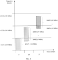
- FIG. 4 is a schematic diagram of an example of a signal transmission method applied to an embodiment of this application.
- an uplink positioning method is used as an example for description.
- a terminal device (a sending end) sends an uplink reference signal
- a network device (a receiving end) receives the reference signal and uses the reference signal for positioning.
- the same method is also applicable to a downlink positioning method, a joint uplink and downlink positioning method, and the like. This is not limited in this application.
- bandwidths of the frequency domain resource #1, the frequency domain resource #2, and the frequency domain resource #3 do not exceed a bandwidth of a single carrier component, for example, do not exceed 100 MHz.
- a bandwidth occupied by a corresponding SRS sequence may be less than or equal to 100 MHz, that is, a length of each SRS sequence is related to a bandwidth size of a corresponding frequency domain resource.
- the SRS#A is generated based on indication information of the frequency domain resource #2.
- the indication information includes at least one of the following: indication information of the BWP2 and the BWP3, and a start frequency, a size, and a range that are of the frequency domain resource #2.
- An SRS#A1 and an SRS#A2 are obtained by truncating the long sequence SRS#A.
- the SRS#A1 corresponds to the BWP2, and the SRS#A2 corresponds to the BWP3.
- the terminal device generates an SRS#B and an SRS#C based on indication information of the frequency domain resource #2.
- the SRS#B and the SRS#C respectively correspond to the BWP2 and the BWP3.
- the indication information includes at least one of the following: indication information of the BWP2 and the BWP3, and a start frequency, a size, and a range that are of the frequency domain resource #2.
- a sequence sent on the BWP2 may be a phase tracking sequence of 5 MHz.
- a sequence sent on the BWP3 may be an SRS sequence.
- the terminal device sends an SRS#1 of 100 MHz on the BWP1 located on the carrier component CC#1.
- the terminal device sends an SRS#A1 of 5 MHz on the BWP2 located on the carrier component CC#1, and sends an SRS#A2 of 95 MHz on the BWP3 located on the carrier component CC#2; and when the foregoing mapping manner 2 is used as an example, the terminal device sends a phase tracking sequence of 5 MHz on the BWP2 located on the carrier component CC#1, and sends an SRS sequence of 95 MHz on the BWP3 located on the carrier component CC#2.
- a third time element 3T the terminal device sends an SRS#4 of 10 MHz on the BWP4 located on the carrier component CC#2, and sends an SRS#5 of 90 MHz on the BWP5 located on the carrier component CC#3. Any two SRS sequences in the SRS#1 to the SRS#5 may be the same or may be different.
- a length of each SRS sequence is related to a bandwidth size of a BWP in which the SRS sequence is located. It should be noted that, each time element T for sending includes an actual signal sending time and a re-tuning time of a phase-locked loop.
- 1T and 2T may be adjacent time elements, or may be non-adjacent time elements, that is, 1T and 2T may be spaced by several symbols or slots.
- 2T and 3T may be adjacent time elements, or may be non-adjacent time elements, that is, 2T and 3T may be spaced by several symbols or slots.
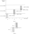
- FIG. 5 FIG. 5 is a schematic diagram of still another information transmission method according to an embodiment of this application for understanding.
- the frequency domain resource #1 partially overlaps with the frequency domain resource #2, namely, the BWP2.
- the overlapping part may be used to estimate a phase difference between the CC#1 and the CC#2.
- the BWP2 may be a newly defined BWP on the carrier component CC#1 (a definition of the newly defined BWP herein is different from that of a current BWP, the newly defined BWP is distributed on at least two carrier components, while the current BWP is distributed on a single carrier component), or may be a part of the BWP1.
- the frequency domain resource #3 partially overlaps with the frequency domain resource #2, namely, an overlapping part between the BWP4 and the BWP3.
- the overlapping part may be used to estimate a phase difference between the CC#2 and the CC#3.
- the terminal device needs to send a signal of the frequency domain resource #2 in a carrier aggregation manner. Similarly, the terminal device needs to send a signal of the frequency domain resource #3 in a carrier aggregation manner.
- FIG. 6 is a schematic diagram of an example of a method for estimating a phase difference according to an embodiment of this application:
- the network device may obtain ⁇ ⁇ through division of h ( t 1 ) and h ( t 2 ) based on channel estimation, that is, h ( t 2 ) / h ( t 1 ) ⁇ e -j ( ⁇ 2 - ⁇ 1 ) .
- another method may be used. This is not limited in the present invention.
- the frequency domain resource #1, the frequency domain resource #2, and the frequency domain resource #3 partially overlap with each other.
- the frequency domain resource #1 and the frequency domain resource #2 partially overlap with each other, for example, the BWP2, and the frequency domain resource #2 and the frequency domain resource #3 may partially overlap with each other, or may not overlap with each other.
- the frequency domain resource #2 and the frequency domain resource #3 partially overlap with each other, and the frequency domain resource #1 and the frequency domain resource #2 may partially overlap with each other, or may not overlap with each other.
- the frequency domain resource #1, the frequency domain resource #2, and the frequency domain resource #3 may be configured and activated by the network device.
- the BWP2 and the BWP3 that correspond to the frequency domain resource #2 need to be simultaneously activated or deactivated by the network device.
- the BWP4 and the BWP5 that correspond to the frequency domain resource #3 need to be simultaneously activated or deactivated by the network device. That is, if one frequency domain resource corresponds to a plurality of BWPs, the plurality of BWPs need to be simultaneously activated or deactivated by the network device.
- the network device correspondingly receives the corresponding signal on each resource, estimates, based on a channel estimation result of the frequency domain overlapping part, a phase difference between two consecutive frequency hopping signals, and then performs phase compensation in time domain, to align signals at several moments to a same phase.
- the network device superimposes, in time domain, signals received at a plurality of (frequency hopping) moments, to restore a large-bandwidth signal.
- the large-bandwidth signal may be used for positioning.
- the terminal device needs to send a signal in a carrier aggregation manner when sending the signal on the frequency domain resource.
- the terminal device does not need to support a carrier aggregation capability when sending data on the frequency domain resource.
- a definition of the new BWP is different from that of a current BWP.
- the new BWP is distributed on at least two carrier components, while the current BWP is distributed on a single carrier component.
- the new carrier component (or may be referred to as an overlapping carrier component overlapping CC) is defined as a carrier component that may span a plurality of current carrier components and may overlap with each other.
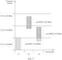
- FIG. 7 is a schematic diagram of another example of a signal transmission method applied to an embodiment of this application.
- an uplink positioning method is used as an example for description.
- a terminal device (a sending end) sends an uplink reference signal
- a network device (a receiving end) receives the reference signal and uses the reference signal for positioning.
- the same method is also applicable to a downlink positioning method, a joint uplink and downlink positioning method, and the like. This is not limited in this application.
- a new BWP (or referred to as a pos-BWP) in FIG. 7 is a BWP defined or configured on one or more carrier components.
- a bandwidth of each pos-BWP does not exceed a bandwidth of one carrier component (for example, 100 MHz).
- a frequency domain resource #1 is a frequency domain resource corresponding to a CC#1.
- the frequency domain resource #1 includes a pos-BWP1, where the pos-BWP1 is located on the CC#1, and a bandwidth of the pos-BWP1 is 100 MHz.
- a frequency domain resource #2 is a frequency domain resource corresponding to a part of a CC#2 and a part of the CC#1.
- bandwidths of the frequency domain resource #1, the frequency domain resource #2, and the frequency domain resource #3 do not exceed a bandwidth of a single carrier component, for example, do not exceed 100 MHz.
- a bandwidth occupied by a corresponding SRS sequence may be less than or equal to 100 MHz, that is, a length of each SRS sequence is related to a bandwidth size of a corresponding frequency domain resource.
- the terminal device sends an SRS#1 of 100 MHz on the pos-BWP1 located on the carrier component CC#1; in a second time element 2T, the terminal device sends an SRS#2 of 100 MHz on the pos-BWP3 located on the carrier component CC#2 and the carrier component CC#3; and in a third time element 3T, the terminal device sends an SRS#3 of 100 MHz on the pos-BWP2 located on the carrier component CC#1 and the carrier component CC#2. Any two SRS sequences in the SRS#1 to the SRS#3 may be the same or may be different.
- each time element T for sending includes an actual signal sending time and a re-tuning time of a phase-locked loop.
- 1T and 2T may be adjacent time elements, or may be non-adjacent time elements, that is, 1T and 2T may be spaced by several symbols or slots.
- 2T and 3T may be adjacent time elements, or may be non-adjacent time elements, that is, 2T and 3T may be spaced by several symbols or slots.
- a case in which 1T and 2T are non-adjacent time elements, and 2T and 3T are non-adjacent time elements is similar to that shown in FIG. 5 . Details are not described herein again.
- the frequency domain resource #1 partially overlaps with the frequency domain resource #2, namely, an overlapping part between the pos-BWP1 and the pos-BWP2.
- the overlapping part may be used to estimate a phase difference between the CC#1 and the CC#2.
- the frequency domain resource #3 partially overlaps with the frequency domain resource #2, namely, an overlapping part between the pos-BWP2 and the pos-BWP3.
- the overlapping part may be used to estimate a phase difference between the CC#2 and the CC#3.
- the frequency domain resource #1, the frequency domain resource #2, and the frequency domain resource #3 partially overlap with each other.
- the frequency domain resource #1 and the frequency domain resource #2 partially overlap with each other, and the frequency domain resource #2 and the frequency domain resource #3 may partially overlap with each other, or may not overlap with each other.
- the frequency domain resource #2 and the frequency domain resource #3 partially overlap with each other, and the frequency domain resource #1 and the frequency domain resource #2 may partially overlap with each other, or may not overlap with each other.
- a manner of generating an SRS sequence is described by using an SRS sequence on the frequency domain resource #2 as an example:
- the terminal device generates an SRS#D based on indication information of the frequency domain resource #2.
- the SRS#D corresponds to the frequency domain resource #2, and a sequence length of the SRS#D is related to a bandwidth size of the frequency domain resource #2.
- the foregoing frequency domain resources may be configured and activated by the network device.
- An initial location of the pos-BWP is configured in the following two manners:
- a Point A of a located primary carrier component is used as a reference point, and the initial location of the pos-BWP is determined through setting a value of offsetTocarrier component.
- offsetTocarrier component may be a negative value.
- the pos-BWP3 is used as an example. CC#3-Point A may be used as a reference point, and offsetTocarrier component is -10. In this case, an initial location of the pos-BWP3 is ((CC#3-Point A) -10).
- a bandwidth of the pos-BWP does not exceed a bandwidth of a carrier component, for example, 100 MHz.
- a lowest frequency of a frequency band supported by a cell is used as a reference point. For example, if the lowest frequency of the frequency band supported by the cell is a lowest frequency of the CC#1, the initial location of pos-BWP#3 is the lowest frequency of the CC#1 plus 190 MHz.
- a new CC#1 is a carrier component defined on an original carrier component CC#1
- a new CC#2 is a carrier component defined on the original carrier component CC#1 and an original carrier component CC#2 and partially overlaps with the new CC#
- a new CC#3 is a carrier component defined on the original carrier component CC#2 and an original carrier component CC#3 and partially overlaps with the new CC#2.
- a frequency domain resource #1 is a frequency domain resource corresponding to the new CC#1.
- the frequency domain resource #1 includes a BWP1, where the BWP1 is located on the new CC#1, and a bandwidth of the BWP1 is 100 MHz.
- a frequency domain resource #2 is a frequency domain resource corresponding to the new CC#2.
- the frequency domain resource #2 includes a BWP2, where the BWP2 is located on the new CC#2, and a bandwidth of the BWP2 is 100 MHz.
- a frequency domain resource #3 is a frequency domain resource corresponding to the new CC#3.
- the frequency domain resource #3 includes a BWP3, where the BWP3 is located on the new CC#3, and a bandwidth of the BWP3 is 100 MHz. It should be understood that, in this embodiment of this application, the terminal device may send corresponding signals on the frequency domain resource #1, the frequency domain resource #2, and the frequency domain resource #3 in a frequency hopping manner. This is not limited in this application.
- bandwidths of the frequency domain resource #1, the frequency domain resource #2, and the frequency domain resource #3 do not exceed a bandwidth of a single carrier component, for example, do not exceed 100 MHz.
- a bandwidth occupied by a corresponding SRS sequence may be less than or equal to 100 MHz, that is, a length of each SRS sequence is related to a bandwidth size of a corresponding frequency domain resource.
- the terminal device sends an SRS#1 of 100 MHz on the BWP1 located on the new carrier component CC#1; in a second time element 2T, the terminal device sends an SRS#2 of 100 MHz on the BWP2 located on the new carrier component CC#2; and in a third time element 3T, the terminal device sends an SRS#3 of 100 MHz on the BWP3 located on the new carrier component CC#3.
- Any two SRS sequences in the SRS#1 to the SRS#3 may be the same or may be different.
- a length of each SRS sequence is related to a bandwidth size of a BWP in which the SRS sequence is located.
- each time element T for sending includes an actual signal sending time and a re-tuning time of a phase-locked loop.
- 1T and 2T may be adjacent time elements, or may be non-adjacent time elements, that is, 1T and 2T may be spaced by several symbols or slots.
- 2T and 3T may be adjacent time elements, or may be non-adjacent time elements, that is, 2T and 3T may be spaced by several symbols or slots.
- a case in which 1T and 2T are non-adjacent time elements, and 2T and 3T are non-adjacent time elements is similar to that shown in FIG. 5 . Details are not described herein again.
- the frequency domain resource #1 partially overlaps with the frequency domain resource #2, namely, an overlapping part between the BWP1 and the BWP2.
- the overlapping part may be used to estimate a phase difference between the new CC#1 and the new CC#2.
- the new CC#2 may be defined on two consecutive currently defined carrier components, and there may be a guard interval between the two consecutive currently defined carrier components, where the guard interval is greater than or equal to 0 Hz.
- the frequency domain resource #3 partially overlaps with the frequency domain resource #2, namely, an overlapping part between the BWP2 and the BWP3.
- the overlapping part may be used to estimate a phase difference between the new CC#2 and the new CC#3, and there may be no interval between the BWP2 and the BWP3.
- a manner of generating an SRS sequence is described by using an SRS sequence on the frequency domain resource #2 as an example:
- the indication information of the frequency domain resource #2 includes at least one of the following: indication information of the BWP2, and a start frequency, a size, and a range that are of the frequency domain resource #2.
- the foregoing frequency domain resources may be configured and activated by the network device on each new carrier component.
- the following uses the frequency domain resource #2 as an example to describe a possible implementation of configuring a frequency domain resource.
- the network device performs configuration in a unit of the new carrier component CC#2, and avoids a conflict with resource allocation of the original carrier component CC#1 through resource scheduling.
- the network device After the terminal device sends each signal on each frequency domain resource and each time element, the network device correspondingly receives each signal on each resource, estimates, based on a channel estimation result of the frequency domain overlapping part, a phase difference between two consecutive frequency hopping signals, and then performs phase compensation in time domain, to align signals at several moments to a same phase.
- the network device superimposes, in time domain, signals received at a plurality of (frequency hopping) moments, to restore a large-bandwidth signal.
- the large-bandwidth signal may be used for positioning.
- FIG. 9 and FIG. 10 are schematic diagrams of possible structures of communication apparatuses according to embodiments of this application.
- the communication apparatuses may implement the functions of the terminal device or the network device in the foregoing method embodiments. Therefore, beneficial effects of the foregoing method embodiments can also be implemented.
- the communication apparatus may be the terminal device in the method 100, or may be the network device in the method 100, or may be a module (for example, a chip) used in the terminal device or an access network device.
- the processing module 202 is configured to generate m signals, where m is a positive integer greater than or equal to 2; and the transceiver module 201 is configured to send the m signals on m resources, where the m resources correspond to m frequency domain resources in frequency domain, the m resources correspond to m time elements in time domain, a first frequency domain resource used by a signal carried in an i th time element is distributed on at least two carrier components, a second frequency domain resource used by a signal carried in a j th time element is distributed on at least one carrier component, there is an overlapping part between the second frequency domain resource and the first frequency domain resource, i is greater than or equal to 1 and less than or equal to m, j is greater than or equal to 1 and less than or equal to m, i and j are positive integers, and i is not equal to j.
- the transceiver module 201 is configured to receive m signals, where m is a positive integer greater than or equal to 2, the m signals are located on m resources, the m resources correspond to m frequency domain resources in frequency domain, the m resources correspond to m time elements in time domain, a first frequency domain resource used by a signal carried in an i th time element is distributed on at least two carrier components, a second frequency domain resource used by a signal carried in a j th time element is distributed on at least one carrier component, there is an overlapping part between the second frequency domain resource and the first frequency domain resource, i is greater than or equal to 1 and less than or equal to m, j is greater than or equal to 1 and less than or equal to m, i and j are positive integers, and i is not equal to j; and the processing module 202 is configured to estimate a phase based on a signal that is carried on a
- transceiver module 201 and the processing module 202, refer to related descriptions in the foregoing method embodiments. Details are not described herein again.
- the communication apparatus 300 includes a processor 310 and an interface circuit 320.
- the processor 310 and the interface circuit 320 are coupled to each other.
- the interface circuit 320 may be a transceiver or an input/output interface.
- the communication apparatus 300 may further include a memory 330, configured to store instructions executed by the processor 310, or store input data needed by the processor 310 to run instructions, or store data generated after the processor 310 runs instructions.
- the chip in the terminal device implements the functions of the terminal device in the foregoing method embodiments.
- the chip in the terminal device receives information from another module (for example, a radio frequency module or an antenna) in the terminal device, and the information is sent by the network device to the terminal device.
- the chip in the terminal device sends information to another module (for example, a radio frequency module or an antenna) in the terminal device, and the information is sent by the terminal device to the network device.
- the processor in embodiments of this application may be a central processing unit (central processing unit, CPU), or may be another general-purpose processor, a digital signal processor (digital signal processor, DSP), an application specific integrated circuit (application specific integrated circuit, ASIC), a field programmable gate array (field programmable gate array, FPGA) or another programmable logic device, a transistor logic device, a hardware component, or any combination thereof.
- the general-purpose processor may be a microprocessor, or may be any conventional processor.
- the method steps in embodiments of this application may be implemented by hardware, or may be implemented by the processor executing software instructions.
- the software instructions may include corresponding software modules.
- the software modules may be stored in a random access memory (random access memory, RAM), a flash memory, a read-only memory (read-only memory, ROM), a programmable read-only memory (programmable ROM, PROM), an erasable programmable read-only memory (erasable PROM, EPROM), an electrically erasable programmable read-only memory (electrically EPROM, EEPROM), a register, a hard disk, a removable hard disk, a CD-ROM, or any other form of storage medium well-known in the art.
- a storage medium is coupled to the processor, so that the processor can read information from the storage medium and write information into the storage medium.
- the storage medium may be a component of the processor.
- the processor and the storage medium may be disposed in an ASIC.
- the ASIC may be located in the access network device or the terminal device.
- the processor and the storage medium may exist in the network device or the terminal device as discrete components.
- All or some of the foregoing embodiments may be implemented by using software, hardware, firmware, or any combination thereof.
- software is used to implement the embodiments, all or some of the embodiments may be implemented in a form of a computer program product.
- the computer program product includes one or more computer programs or instructions. When the computer programs or instructions are loaded and executed on a computer, all or some of the processes or the functions in embodiments of this application are performed.
- the computer may be a general-purpose computer, a dedicated computer, a computer network, or another programmable apparatus.
- the computer programs or instructions may be stored in a computer-readable storage medium, or may be transmitted through the computer-readable storage medium.
- the computer-readable storage medium may be any usable medium accessible by a computer, or a data storage device, such as a server integrating one or more usable media.
- the usable medium may be a magnetic medium, for example, a floppy disk, a hard disk, or a magnetic tape; or may be an optical medium, for example, a DVD; or may be a semiconductor medium, for example, a solid state disk (solid state disk, SSD).
- “at least one” means one or more, and "a plurality of” means two or more.
- “And/or” describes an association relationship between associated objects and represents that three relationships may exist. For example, A and/or B may represent the following cases: Only A exists, both A and B exist, and only B exists, where A and B may be singular or plural.
- the character “/” usually indicates an “or” relationship between the associated objects. In a formula in this application, the character “/” indicates a "division" relationship between the associated objects.
Landscapes
- Engineering & Computer Science (AREA)
- Signal Processing (AREA)
- Computer Networks & Wireless Communication (AREA)
- Physics & Mathematics (AREA)
- General Physics & Mathematics (AREA)
- Radar, Positioning & Navigation (AREA)
- Remote Sensing (AREA)
- Mobile Radio Communication Systems (AREA)
Applications Claiming Priority (2)
| Application Number | Priority Date | Filing Date | Title |
|---|---|---|---|
| CN202110374471.9A CN115189853A (zh) | 2021-04-07 | 2021-04-07 | 一种信号传输方法和装置 |
| PCT/CN2022/083766 WO2022213849A1 (zh) | 2021-04-07 | 2022-03-29 | 一种信号传输方法和装置 |
Publications (2)
| Publication Number | Publication Date |
|---|---|
| EP4297320A1 true EP4297320A1 (de) | 2023-12-27 |
| EP4297320A4 EP4297320A4 (de) | 2024-07-31 |
Family
ID=83511608
Family Applications (1)
| Application Number | Title | Priority Date | Filing Date |
|---|---|---|---|
| EP22783916.4A Pending EP4297320A4 (de) | 2021-04-07 | 2022-03-29 | Signalübertragungsverfahren und -vorrichtung |
Country Status (4)
| Country | Link |
|---|---|
| US (1) | US12604303B2 (de) |
| EP (1) | EP4297320A4 (de) |
| CN (1) | CN115189853A (de) |
| WO (1) | WO2022213849A1 (de) |
Families Citing this family (5)
| Publication number | Priority date | Publication date | Assignee | Title |
|---|---|---|---|---|
| CN115642931A (zh) * | 2021-07-19 | 2023-01-24 | 华为技术有限公司 | 一种数据传输方法和装置 |
| CN118057742A (zh) * | 2022-11-18 | 2024-05-21 | 华为技术有限公司 | 一种信号发送方法及装置 |
| CN118784486A (zh) * | 2023-04-07 | 2024-10-15 | 中国移动通信有限公司研究院 | 通信处理方法、装置、设备及可读存储介质 |
| CN120264468A (zh) * | 2024-01-03 | 2025-07-04 | 华为技术有限公司 | 一种通信方法和装置 |
| CN121645498A (zh) * | 2024-09-05 | 2026-03-10 | 华为技术有限公司 | 通信方法和通信装置 |
Family Cites Families (11)
| Publication number | Priority date | Publication date | Assignee | Title |
|---|---|---|---|---|
| KR101651682B1 (ko) * | 2010-02-16 | 2016-08-26 | 삼성전자주식회사 | 다중 반송파를 사용하는 이동 통신 시스템에서 반송파 컴퍼넌트를 통해 데이터를 송수신하는 방법 및 장치 |
| US9936498B2 (en) * | 2014-11-04 | 2018-04-03 | Qualcomm Incorporated | High reliability low latency mission critical communication |
| CN105589506B (zh) | 2016-02-29 | 2017-10-17 | 华为技术有限公司 | 功率跟踪方法、装置及光伏发电系统 |
| EP3316534A1 (de) * | 2016-10-27 | 2018-05-02 | Fraunhofer Gesellschaft zur Förderung der Angewand | Kanalschätzung von frequenzteilbändern |
| US10708021B2 (en) * | 2017-08-11 | 2020-07-07 | Lg Electronics Inc. | Method for transmitting SRS in a wireless communication system and apparatus therefor |
| CN109586869B (zh) * | 2017-09-29 | 2021-08-06 | 中国移动通信有限公司研究院 | Srs发送方法、相位差处理方法、通信设备及存储介质 |
| CN109451805B (zh) * | 2017-09-29 | 2021-09-21 | 北京小米移动软件有限公司 | 参考信号的传输及接收方法、装置、基站和用户设备 |
| WO2019194589A1 (ko) * | 2018-04-05 | 2019-10-10 | 한국전자통신연구원 | 통신 시스템에서 상향링크 전송을 위한 방법 및 장치 |
| CN110891312B (zh) * | 2018-09-10 | 2023-11-03 | 华为技术有限公司 | 一种信息发送方法,信息接收的方法和装置 |
| CN111869156B (zh) * | 2020-06-16 | 2023-10-03 | 北京小米移动软件有限公司 | 参考信号资源的配置方法、装置、通信设备及存储介质 |
| US20220078798A1 (en) * | 2020-09-09 | 2022-03-10 | Qualcomm Incorporated | Radio frequency considerations for bandwidth part (bwp) selection |
-
2021
- 2021-04-07 CN CN202110374471.9A patent/CN115189853A/zh active Pending
-
2022
- 2022-03-29 WO PCT/CN2022/083766 patent/WO2022213849A1/zh not_active Ceased
- 2022-03-29 EP EP22783916.4A patent/EP4297320A4/de active Pending
-
2023
- 2023-10-05 US US18/481,785 patent/US12604303B2/en active Active
Also Published As
| Publication number | Publication date |
|---|---|
| EP4297320A4 (de) | 2024-07-31 |
| WO2022213849A1 (zh) | 2022-10-13 |
| US12604303B2 (en) | 2026-04-14 |
| CN115189853A (zh) | 2022-10-14 |
| US20240040554A1 (en) | 2024-02-01 |
Similar Documents
| Publication | Publication Date | Title |
|---|---|---|
| EP4297320A1 (de) | Signalübertragungsverfahren und -vorrichtung | |
| US12200755B2 (en) | Control resource set information in physical broadcast channel | |
| KR102557553B1 (ko) | 통신 방법 및 통신 디바이스 | |
| US11540309B2 (en) | Data transmission method and apparatus | |
| EP3456137B1 (de) | Design eines physikalischen direktzugriffskanals (prach) | |
| US20200221508A1 (en) | Paging Method and Apparatus and Communication Timing Method and Apparatus | |
| US10893548B2 (en) | Physical random access channel design for licensed assisted access | |
| JP2025510053A (ja) | 通信方法および通信装置 | |
| WO2019062003A1 (zh) | 数据传输的方法、终端设备和网络设备 | |
| EP2647251B1 (de) | Implizite betriebsmittelzuweisung unter verwendung einer verschobenen synchronisationssequenz | |
| US11425703B2 (en) | Method for transmitting signal, network device and terminal device | |
| US20180262975A1 (en) | Air interface resource utilization techniques for wireless communication networks | |
| US11146374B2 (en) | Transmission method and transmission apparatus | |
| EP3371923A1 (de) | Messungen vpn kanalzustandsinformationen (csi) und csi-meldung in lizenziertem unterstütztem zugriff (laa) | |
| US11140712B2 (en) | Transmission of (E)PDCCH within partial subframe in licensed assisted access (LAA) | |
| US12574170B2 (en) | Method, device and computer storage medium for communication | |
| US11539485B2 (en) | Reference signal transmission method and device | |
| CN112314034A (zh) | 信息发送和接收方法以及装置 | |
| WO2022183455A1 (zh) | 一种随机接入资源确定方法、电子设备及存储介质 | |
| CN115225127A (zh) | 用户设备的装置和方法 | |
| WO2017196896A1 (en) | Phase compensation reference signal for 5g systems | |
| CN112586063A (zh) | 一种测量控制方法、终端设备及网络设备 | |
| CN111837430B (zh) | 无线通信的方法、终端设备和网络设备 | |
| EP4358618A1 (de) | Konfigurationsverfahren und kommunikationsvorrichtung |
Legal Events
| Date | Code | Title | Description |
|---|---|---|---|
| STAA | Information on the status of an ep patent application or granted ep patent |
Free format text: STATUS: THE INTERNATIONAL PUBLICATION HAS BEEN MADE |
|
| PUAI | Public reference made under article 153(3) epc to a published international application that has entered the european phase |
Free format text: ORIGINAL CODE: 0009012 |
|
| STAA | Information on the status of an ep patent application or granted ep patent |
Free format text: STATUS: REQUEST FOR EXAMINATION WAS MADE |
|
| 17P | Request for examination filed |
Effective date: 20230918 |
|
| AK | Designated contracting states |
Kind code of ref document: A1 Designated state(s): AL AT BE BG CH CY CZ DE DK EE ES FI FR GB GR HR HU IE IS IT LI LT LU LV MC MK MT NL NO PL PT RO RS SE SI SK SM TR |
|
| DAV | Request for validation of the european patent (deleted) | ||
| DAX | Request for extension of the european patent (deleted) | ||
| A4 | Supplementary search report drawn up and despatched |
Effective date: 20240703 |
|
| RIC1 | Information provided on ipc code assigned before grant |
Ipc: H04W 4/02 20180101ALI20240627BHEP Ipc: H04L 5/00 20060101AFI20240627BHEP |
|
| STAA | Information on the status of an ep patent application or granted ep patent |
Free format text: STATUS: EXAMINATION IS IN PROGRESS |
|
| 17Q | First examination report despatched |
Effective date: 20251217 |