EP4297539A1 - Elektronische vorrichtung mit flexibler leiterplatte - Google Patents
Elektronische vorrichtung mit flexibler leiterplatte Download PDFInfo
- Publication number
- EP4297539A1 EP4297539A1 EP22833360.5A EP22833360A EP4297539A1 EP 4297539 A1 EP4297539 A1 EP 4297539A1 EP 22833360 A EP22833360 A EP 22833360A EP 4297539 A1 EP4297539 A1 EP 4297539A1
- Authority
- EP
- European Patent Office
- Prior art keywords
- printed circuit
- circuit board
- flexible printed
- electronic device
- disposed
- Prior art date
- Legal status (The legal status is an assumption and is not a legal conclusion. Google has not performed a legal analysis and makes no representation as to the accuracy of the status listed.)
- Pending
Links
Images






Classifications
-
- H—ELECTRICITY
- H04—ELECTRIC COMMUNICATION TECHNIQUE
- H04M—TELEPHONIC COMMUNICATION
- H04M1/00—Substation equipment, e.g. for use by subscribers
- H04M1/02—Constructional features of telephone sets
- H04M1/0202—Portable telephone sets, e.g. cordless phones, mobile phones or bar type handsets
- H04M1/0206—Portable telephones comprising a plurality of mechanically joined movable body parts, e.g. hinged housings
- H04M1/0208—Portable telephones comprising a plurality of mechanically joined movable body parts, e.g. hinged housings characterized by the relative motions of the body parts
- H04M1/0214—Foldable telephones, i.e. with body parts pivoting to an open position around an axis parallel to the plane they define in closed position
- H04M1/0216—Foldable in one direction, i.e. using a one degree of freedom hinge
-
- H—ELECTRICITY
- H04—ELECTRIC COMMUNICATION TECHNIQUE
- H04M—TELEPHONIC COMMUNICATION
- H04M1/00—Substation equipment, e.g. for use by subscribers
- H04M1/02—Constructional features of telephone sets
- H04M1/0202—Portable telephone sets, e.g. cordless phones, mobile phones or bar type handsets
- H04M1/026—Details of the structure or mounting of specific components
- H04M1/0277—Details of the structure or mounting of specific components for a printed circuit board assembly
-
- H—ELECTRICITY
- H05—ELECTRIC TECHNIQUES NOT OTHERWISE PROVIDED FOR
- H05K—PRINTED CIRCUITS; CASINGS OR CONSTRUCTIONAL DETAILS OF ELECTRIC APPARATUS; MANUFACTURE OF ASSEMBLAGES OF ELECTRICAL COMPONENTS
- H05K1/00—Printed circuits
- H05K1/02—Details
- H05K1/0277—Bendability or stretchability details
- H05K1/028—Bending or folding regions of flexible printed circuits
- H05K1/0281—Reinforcement details thereof
-
- G—PHYSICS
- G06—COMPUTING OR CALCULATING; COUNTING
- G06F—ELECTRIC DIGITAL DATA PROCESSING
- G06F1/00—Details not covered by groups G06F3/00 - G06F13/00 and G06F21/00
- G06F1/16—Constructional details or arrangements
- G06F1/1613—Constructional details or arrangements for portable computers
- G06F1/1633—Constructional details or arrangements of portable computers not specific to the type of enclosures covered by groups G06F1/1615 - G06F1/1626
- G06F1/1637—Details related to the display arrangement, including those related to the mounting of the display in the housing
- G06F1/1647—Details related to the display arrangement, including those related to the mounting of the display in the housing including at least an additional display
-
- G—PHYSICS
- G06—COMPUTING OR CALCULATING; COUNTING
- G06F—ELECTRIC DIGITAL DATA PROCESSING
- G06F1/00—Details not covered by groups G06F3/00 - G06F13/00 and G06F21/00
- G06F1/16—Constructional details or arrangements
- G06F1/1613—Constructional details or arrangements for portable computers
- G06F1/1633—Constructional details or arrangements of portable computers not specific to the type of enclosures covered by groups G06F1/1615 - G06F1/1626
- G06F1/1637—Details related to the display arrangement, including those related to the mounting of the display in the housing
- G06F1/1652—Details related to the display arrangement, including those related to the mounting of the display in the housing the display being flexible, e.g. mimicking a sheet of paper, or rollable
-
- G—PHYSICS
- G06—COMPUTING OR CALCULATING; COUNTING
- G06F—ELECTRIC DIGITAL DATA PROCESSING
- G06F1/00—Details not covered by groups G06F3/00 - G06F13/00 and G06F21/00
- G06F1/16—Constructional details or arrangements
- G06F1/1613—Constructional details or arrangements for portable computers
- G06F1/1633—Constructional details or arrangements of portable computers not specific to the type of enclosures covered by groups G06F1/1615 - G06F1/1626
- G06F1/1656—Details related to functional adaptations of the enclosure, e.g. to provide protection against EMI, shock, water, or to host detachable peripherals like a mouse or removable expansions units like PCMCIA cards, or to provide access to internal components for maintenance or to removable storage supports like CDs or DVDs, or to mechanically mount accessories
-
- G—PHYSICS
- G06—COMPUTING OR CALCULATING; COUNTING
- G06F—ELECTRIC DIGITAL DATA PROCESSING
- G06F1/00—Details not covered by groups G06F3/00 - G06F13/00 and G06F21/00
- G06F1/16—Constructional details or arrangements
- G06F1/1613—Constructional details or arrangements for portable computers
- G06F1/1633—Constructional details or arrangements of portable computers not specific to the type of enclosures covered by groups G06F1/1615 - G06F1/1626
- G06F1/1675—Miscellaneous details related to the relative movement between the different enclosures or enclosure parts
- G06F1/1681—Details related solely to hinges
-
- G—PHYSICS
- G06—COMPUTING OR CALCULATING; COUNTING
- G06F—ELECTRIC DIGITAL DATA PROCESSING
- G06F1/00—Details not covered by groups G06F3/00 - G06F13/00 and G06F21/00
- G06F1/16—Constructional details or arrangements
- G06F1/1613—Constructional details or arrangements for portable computers
- G06F1/1633—Constructional details or arrangements of portable computers not specific to the type of enclosures covered by groups G06F1/1615 - G06F1/1626
- G06F1/1675—Miscellaneous details related to the relative movement between the different enclosures or enclosure parts
- G06F1/1683—Miscellaneous details related to the relative movement between the different enclosures or enclosure parts for the transmission of signal or power between the different housings, e.g. details of wired or wireless communication, passage of cabling
-
- H—ELECTRICITY
- H04—ELECTRIC COMMUNICATION TECHNIQUE
- H04M—TELEPHONIC COMMUNICATION
- H04M1/00—Substation equipment, e.g. for use by subscribers
- H04M1/02—Constructional features of telephone sets
- H04M1/0202—Portable telephone sets, e.g. cordless phones, mobile phones or bar type handsets
- H04M1/026—Details of the structure or mounting of specific components
- H04M1/0266—Details of the structure or mounting of specific components for a display module assembly
- H04M1/0268—Details of the structure or mounting of specific components for a display module assembly including a flexible display panel
- H04M1/0269—Details of the structure or mounting of specific components for a display module assembly including a flexible display panel mounted in a fixed curved configuration, e.g. display curved around the edges of the telephone housing
-
- H—ELECTRICITY
- H05—ELECTRIC TECHNIQUES NOT OTHERWISE PROVIDED FOR
- H05K—PRINTED CIRCUITS; CASINGS OR CONSTRUCTIONAL DETAILS OF ELECTRIC APPARATUS; MANUFACTURE OF ASSEMBLAGES OF ELECTRICAL COMPONENTS
- H05K1/00—Printed circuits
- H05K1/02—Details
- H05K1/0277—Bendability or stretchability details
- H05K1/0283—Stretchable printed circuits
-
- H—ELECTRICITY
- H05—ELECTRIC TECHNIQUES NOT OTHERWISE PROVIDED FOR
- H05K—PRINTED CIRCUITS; CASINGS OR CONSTRUCTIONAL DETAILS OF ELECTRIC APPARATUS; MANUFACTURE OF ASSEMBLAGES OF ELECTRICAL COMPONENTS
- H05K1/00—Printed circuits
- H05K1/18—Printed circuits structurally associated with non-printed electric components
- H05K1/189—Printed circuits structurally associated with non-printed electric components characterised by the use of flexible or folded printed circuits
-
- H—ELECTRICITY
- H05—ELECTRIC TECHNIQUES NOT OTHERWISE PROVIDED FOR
- H05K—PRINTED CIRCUITS; CASINGS OR CONSTRUCTIONAL DETAILS OF ELECTRIC APPARATUS; MANUFACTURE OF ASSEMBLAGES OF ELECTRICAL COMPONENTS
- H05K5/00—Casings, cabinets or drawers for electric apparatus
- H05K5/02—Details
- H05K5/03—Covers
-
- H—ELECTRICITY
- H05—ELECTRIC TECHNIQUES NOT OTHERWISE PROVIDED FOR
- H05K—PRINTED CIRCUITS; CASINGS OR CONSTRUCTIONAL DETAILS OF ELECTRIC APPARATUS; MANUFACTURE OF ASSEMBLAGES OF ELECTRICAL COMPONENTS
- H05K5/00—Casings, cabinets or drawers for electric apparatus
- H05K5/06—Hermetically-sealed casings
-
- H—ELECTRICITY
- H04—ELECTRIC COMMUNICATION TECHNIQUE
- H04M—TELEPHONIC COMMUNICATION
- H04M1/00—Substation equipment, e.g. for use by subscribers
- H04M1/02—Constructional features of telephone sets
- H04M1/0202—Portable telephone sets, e.g. cordless phones, mobile phones or bar type handsets
- H04M1/026—Details of the structure or mounting of specific components
- H04M1/0266—Details of the structure or mounting of specific components for a display module assembly
- H04M1/0268—Details of the structure or mounting of specific components for a display module assembly including a flexible display panel
-
- H—ELECTRICITY
- H05—ELECTRIC TECHNIQUES NOT OTHERWISE PROVIDED FOR
- H05K—PRINTED CIRCUITS; CASINGS OR CONSTRUCTIONAL DETAILS OF ELECTRIC APPARATUS; MANUFACTURE OF ASSEMBLAGES OF ELECTRICAL COMPONENTS
- H05K1/00—Printed circuits
- H05K1/02—Details
-
- H—ELECTRICITY
- H05—ELECTRIC TECHNIQUES NOT OTHERWISE PROVIDED FOR
- H05K—PRINTED CIRCUITS; CASINGS OR CONSTRUCTIONAL DETAILS OF ELECTRIC APPARATUS; MANUFACTURE OF ASSEMBLAGES OF ELECTRICAL COMPONENTS
- H05K2201/00—Indexing scheme relating to printed circuits covered by H05K1/00
- H05K2201/20—Details of printed circuits not provided for in H05K2201/01 - H05K2201/10
- H05K2201/2009—Reinforced areas, e.g. for a specific part of a flexible printed circuit
Definitions
- the disclosure relates to an electronic device including a flexible printed circuit board (FPCB).
- FPCB flexible printed circuit board
- Electronic device may mean a device performing a particular function according to its equipped program, such as a home appliance, an electronic scheduler, a portable multimedia player, a mobile communication terminal, a tablet personal computer (PC), a video/sound device, a desktop PC or laptop computer, a navigation for automobile, etc.
- electronic devices may output stored information as voices or images.
- an electronic device such as a mobile communication terminal, is recently being equipped with various functions.
- an electronic device comes with the integrated functionality, including an entertainment function, such as playing video games, a multimedia function, such as replaying music/videos, a communication and security function for mobile banking, and a scheduling or e-wallet function.
- Such electronic devices become compact enough for users to carry in a convenient way.
- multimedia services As mobile communication services spread up to multimedia services, users may use multimedia services as well as voice calls or text messaging, on their electronic device. To rid the user of any inconvenience in using multimedia services, a trend is to pack an electronic device with a larger display panel. Recently, flexible display panel-equipped foldable electronic devices come along.
- An electronic device may include a housing and may include a plurality of inner spaces (e.g., a waterproof area and a non-waterproof area) defined by structures disposed inside the housing.
- the electronic device may include various electronic components for performing various functions and operations, such as communication, entertainment, multimedia, security, etc., and among these electronic components, important electrical components may be disposed in the waterproof area considering the interface for user convenience, product regulations, and spatial arrangement in electronic devices.
- Electronic components such as a printed circuit board (PCB), disposed in the waterproof area may be electrically coupled through at least one flexible printed circuit board (FPCB).
- PCB printed circuit board
- FPCB flexible printed circuit board
- a through hole or an opening through which the flexible printed circuit board passes may be formed in at least partial area of the inner walls (e.g., the wall of the housing) surrounding the waterproof area, and a waterproofing member implemented with an elastic material is provided in the insertion portion of the flexible printed circuit board passing through the through hole so that the space between the through hole and the insertion portion of the flexible printed circuit board may be closed and waterproofed by the waterproofing member.
- a waterproofing member implemented with an elastic material is provided in the insertion portion of the flexible printed circuit board passing through the through hole so that the space between the through hole and the insertion portion of the flexible printed circuit board may be closed and waterproofed by the waterproofing member.
- the rigidity of the flexible printed circuit board is significant, if external force is applied to the waterproofing member coupled in the through hole, the waterproofing member may be deformed, forming a gap between the through hole and the insertion portion of the flexible printed circuit board and thus causing a fluid (e.g., water) to enter the waterproof area.
- an aspect of the disclosure is to provide an electronic device for providing a flexible printed circuit board including a reinforced portion which is inserted into a through hole with a relatively larger width than other portions of the flexible printed circuit board, thereby providing rigidity to the waterproofing member, which hangs down in the shape of a cantilever, and reducing deformation due to external force to thereby enhance the waterproofness of the waterproof area.
- Another aspect of the disclosure is to provide an electronic device for providing a reinforced portion of a flexible printed circuit board including a predetermined bonding member between a plurality of layers, reducing inter-layer peel-off and enhancing the rigidity of the reinforced portion by the bonding member, and thus enhancing the waterproofness of the waterproof area.
- an electronic device that may provide a flexible printed circuit board including a reinforced portion which is inserted into a through hole with a relatively larger width than other portions of the flexible printed circuit board, thereby providing rigidity to the waterproofing member, which hangs down in the shape of a cantilever, and reducing deformation due to external force to thereby enhance the waterproofness of the waterproof area is provided.
- an electronic device that may provide a reinforced portion of a flexible printed circuit board including a predetermined bonding member between a plurality of layers, reducing inter-layer peel-off and enhancing the rigidity of the reinforced portion by the bonding member, and thus enhancing the waterproofness of the waterproof area is provided.
- FIG. 1 is a block diagram illustrating an electronic device 101 in a network environment 100 according to an embodiment of the disclosure.
- the electronic device 101 in the network environment 100 may communicate with at least one of an electronic device 102 via a first network 198 (e.g., a short-range wireless communication network), or an electronic device 104 or a server 108 via a second network 199 (e.g., a long-range wireless communication network).
- the electronic device 101 may communicate with the electronic device 104 via the server 108.
- the processor 120 may execute, for example, software (e.g., a program 140) to control at least one other component (e.g., a hardware or software component) of the electronic device 101 coupled with the processor 120, and may perform various data processing or computation. According to one embodiment, as at least part of the data processing or computation, the processor 120 may store a command or data received from another component (e.g., the sensor module 176 or the communication module 190) in volatile memory 132, process the command or the data stored in the volatile memory 132, and store resulting data in non-volatile memory 134.
- software e.g., a program 140
- the processor 120 may store a command or data received from another component (e.g., the sensor module 176 or the communication module 190) in volatile memory 132, process the command or the data stored in the volatile memory 132, and store resulting data in non-volatile memory 134.
- the processor 120 may include a main processor 121 (e.g., a central processing unit (CPU) or an application processor (AP)), or an auxiliary processor 123 (e.g., a graphics processing unit (GPU), a neural processing unit (NPU), an image signal processor (ISP), a sensor hub processor, or a communication processor (CP)) that is operable independently from, or in conjunction with, the main processor 121.
- a main processor 121 e.g., a central processing unit (CPU) or an application processor (AP)
- auxiliary processor 123 e.g., a graphics processing unit (GPU), a neural processing unit (NPU), an image signal processor (ISP), a sensor hub processor, or a communication processor (CP)
- the main processor 121 may be configured to use lower power than the main processor 121 or to be specified for a designated function.
- the auxiliary processor 123 may be implemented as separate from, or as part of the main processor 121.
- the auxiliary processor 123 may control at least some of functions or states related to at least one component (e.g., the display module 160, the sensor module 176, or the communication module 190) among the components of the electronic device 101, instead of the main processor 121 while the main processor 121 is in an inactive (e.g., sleep) state, or together with the main processor 121 while the main processor 121 is in an active state (e.g., executing an application).
- the auxiliary processor 123 e.g., an image signal processor or a communication processor
- the auxiliary processor 123 may include a hardware structure specified for artificial intelligence model processing.
- the artificial intelligence model may be generated via machine learning. Such learning may be performed, e.g., by the electronic device 101 where the artificial intelligence is performed or via a separate server (e.g., the server 108). Learning algorithms may include, but are not limited to, e.g., supervised learning, unsupervised learning, semi-supervised learning, or reinforcement learning.
- the artificial intelligence model may include a plurality of artificial neural network layers.
- the artificial neural network may be a deep neural network (DNN), a convolutional neural network (CNN), a recurrent neural network (RNN), a restricted Boltzmann machine (RBM), a deep belief network (DBN), a bidirectional recurrent deep neural network (BRDNN), deep Q-network or a combination of two or more thereof but is not limited thereto.
- the artificial intelligence model may, additionally or alternatively, include a software structure other than the hardware structure.
- the input module 150 may receive a command or data to be used by other component (e.g., the processor 120) of the electronic device 101, from the outside (e.g., a user) of the electronic device 101.
- the input module 150 may include, for example, a microphone, a mouse, a keyboard, keys (e.g., buttons), or a digital pen (e.g., a stylus pen).
- the sound output module 155 may output sound signals to the outside of the electronic device 101.
- the sound output module 155 may include, for example, a speaker or a receiver.
- the speaker may be used for general purposes, such as playing multimedia or playing record.
- the receiver may be used for receiving incoming calls. According to an embodiment, the receiver may be implemented as separate from, or as part of the speaker.
- the display module 160 may visually provide information to the outside (e.g., a user) of the electronic device 101.
- the display 160 may include, for example, a display, a hologram device, or a projector and control circuitry to control a corresponding one of the display, hologram device, and projector.
- the display 160 may include a touch sensor configured to detect a touch, or a pressure sensor configured to measure the intensity of a force generated by the touch.
- the audio module 170 may convert a sound into an electrical signal and vice versa. According to an embodiment, the audio module 170 may obtain the sound via the input module 150, or output the sound via the sound output module 155 or a headphone of an external electronic device (e.g., an electronic device 102) directly (e.g., wiredly) or wirelessly coupled with the electronic device 101.
- an external electronic device e.g., an electronic device 102
- directly e.g., wiredly
- wirelessly e.g., wirelessly
- the sensor module 176 may detect an operational state (e.g., power or temperature) of the electronic device 101 or an environmental state (e.g., a state of a user) external to the electronic device 101, and then generate an electrical signal or data value corresponding to the detected state.
- the sensor module 176 may include, for example, a gesture sensor, a gyro sensor, an atmospheric pressure sensor, a magnetic sensor, an acceleration sensor, a grip sensor, a proximity sensor, a color sensor, an infrared (IR) sensor, a biometric sensor, a temperature sensor, a humidity sensor, or an illuminance sensor.
- the interface 177 may support one or more specified protocols to be used for the electronic device 101 to be coupled with the external electronic device (e.g., the electronic device 102) directly (e.g., wiredly) or wirelessly.
- the interface 177 may include, for example, a high definition multimedia interface (HDMI), a universal serial bus (USB) interface, a secure digital (SD) card interface, or an audio interface.
- HDMI high definition multimedia interface
- USB universal serial bus
- SD secure digital
- a connecting terminal 178 may include a connector via which the electronic device 101 may be physically connected with the external electronic device (e.g., the electronic device 102).
- the connecting terminal 178 may include, for example, a HDMI connector, a USB connector, a SD card connector, or an audio connector (e.g., a headphone connector).
- the camera module 180 may capture a still image or moving images.
- the camera module 180 may include one or more lenses, image sensors, image signal processors, or flashes.
- the power management module 188 may manage power supplied to the electronic device 101.
- the power management module 188 may be implemented as at least part of, for example, a power management integrated circuit (PMIC).
- PMIC power management integrated circuit
- the battery 189 may supply power to at least one component of the electronic device 101.
- the battery 189 may include, for example, a primary cell which is not rechargeable, a secondary cell which is rechargeable, or a fuel cell.
- the communication module 190 may include a wireless communication module 192 (e.g., a cellular communication module, a short-range wireless communication module, or a global navigation satellite system (GNSS) communication module) or a wired communication module 194 (e.g., a local area network (LAN) communication module or a power line communication (PLC) module).
- a wireless communication module 192 e.g., a cellular communication module, a short-range wireless communication module, or a global navigation satellite system (GNSS) communication module
- GNSS global navigation satellite system
- wired communication module 194 e.g., a local area network (LAN) communication module or a power line communication (PLC) module.
- LAN local area network
- PLC power line communication
- the wireless communication module 192 may identify or authenticate the electronic device 101 in a communication network, such as the first network 198 or the second network 199, using subscriber information (e.g., international mobile subscriber identity (IMSI)) stored in the subscriber identification module 196.
- subscriber information e.g., international mobile subscriber identity (IMSI)
- the wireless communication module 192 may support a 5G network, after a 4th generation (4G) network, and next-generation communication technology, e.g., new radio (NR) access technology.
- the NR access technology may support enhanced mobile broadband (eMBB), massive machine type communications (mMTC), or ultra-reliable and low-latency communications (URLLC).
- eMBB enhanced mobile broadband
- mMTC massive machine type communications
- URLLC ultra-reliable and low-latency communications
- the wireless communication module 192 may support a high-frequency band (e.g., the mmWave band) to achieve, e.g., a high data transmission rate.
- the wireless communication module 192 may support a peak data rate (e.g., 20Gbps or more) for implementing eMBB, loss coverage (e.g., 164dB or less) for implementing mMTC, or U-plane latency (e.g., 0.5ms or less for each of downlink (DL) and uplink (UL), or a round trip of 1ms or less) for implementing URLLC.
- a peak data rate e.g., 20Gbps or more
- loss coverage e.g., 164dB or less
- U-plane latency e.g., 0.5ms or less for each of downlink (DL) and uplink (UL), or a round trip of 1ms or less
- the antenna module 197 may transmit or receive a signal or power to or from the outside (e.g., the external electronic device).
- the antenna module 197 may include one antenna including a radiator formed of a conductor or conductive pattern formed on a substrate (e.g., a printed circuit board (PCB)).
- the antenna module 197 may include a plurality of antennas (e.g., an antenna array). In this case, at least one antenna appropriate for a communication scheme used in a communication network, such as the first network 198 or the second network 199, may be selected from the plurality of antennas by, e.g., the communication module 190.
- the antenna module 197 may form a mmWave antenna module.
- the mmWave antenna module may include a printed circuit board, a RFIC disposed on a first surface (e.g., the bottom surface) of the printed circuit board, or adjacent to the first surface and capable of supporting a designated high-frequency band (e.g., the mmWave band), and a plurality of antennas (e.g., array antennas) disposed on a second surface (e.g., the top or a side surface) of the printed circuit board, or adjacent to the second surface and capable of transmitting or receiving signals of the designated high-frequency band.
- a RFIC disposed on a first surface (e.g., the bottom surface) of the printed circuit board, or adjacent to the first surface and capable of supporting a designated high-frequency band (e.g., the mmWave band)
- a plurality of antennas e.g., array antennas
- At least some of the above-described components may be coupled mutually and communicate signals (e.g., commands or data) therebetween via an inter-peripheral communication scheme (e.g., a bus, general purpose input and output (GPIO), serial peripheral interface (SPI), or mobile industry processor interface (MIPI)).
- an inter-peripheral communication scheme e.g., a bus, general purpose input and output (GPIO), serial peripheral interface (SPI), or mobile industry processor interface (MIPI)
- commands or data may be transmitted or received between the electronic device 101 and the external electronic device 104 via the server 108 coupled with the second network 199.
- the external electronic devices 102 or 104 each may be a device of the same or a different type from the electronic device 101.
- all or some of operations to be executed at the electronic device 101 may be executed at one or more of the external electronic devices 102, 104, or 108. For example, if the electronic device 101 should perform a function or a service automatically, or in response to a request from a user or another device, the electronic device 101, instead of, or in addition to, executing the function or the service, may request the one or more external electronic devices to perform at least part of the function or the service.
- the one or more external electronic devices receiving the request may perform the at least part of the function or the service requested, or an additional function or an additional service related to the request, and transfer an outcome of the performing to the electronic device 101.
- the electronic device 101 may provide the outcome, with or without further processing of the outcome, as at least part of a reply to the request.
- a cloud computing, distributed computing, mobile edge computing (MEC), or client-server computing technology may be used, for example.
- the electronic device 101 may provide ultra low-latency services using, e.g., distributed computing or mobile edge computing.
- the external electronic device 104 may include an internet-of things (IoT) device.
- the server 108 may be an intelligent server using machine learning and/or a neural network.
- the external electronic device 104 or the server 108 may be included in the second network 199.
- the electronic device 101 may be applied to intelligent services (e.g., smart home, smart city, smart car, or health-care) based on 5G communication technology or IoT-related technology.
- the electronic device may be one of various types of electronic devices.
- the electronic devices may include, for example, a portable communication device (e.g., a smart phone), a computer device, a portable multimedia device, a portable medical device, a camera, an electronic device, or a home appliance.
- a portable communication device e.g., a smart phone
- a computer device e.g
- each of such phrases as “A or B,” “at least one of A and B,” “at least one of A or B,” “A, B, or C,” “at least one of A, B, and C,” and “at least one of A, B, or C,” may include all possible combinations of the items enumerated together in a corresponding one of the phrases.
- such terms as “1st” and “2nd,” or “first” and “second” may be used to simply distinguish a corresponding component from another, and does not limit the components in other aspect (e.g., importance or order).
- an element e.g., a first element
- the element may be coupled with the other element directly (e.g., wiredly), wirelessly, or via a third element.
- module may include a unit implemented in hardware, software, or firmware, and may interchangeably be used with other terms, for example, “logic,” “logic block,” “part,” or “circuitry”.
- a module may be a single integral component, or a minimum unit or part thereof, adapted to perform one or more functions.
- the module may be implemented in a form of an application-specific integrated circuit (ASIC).
- ASIC application-specific integrated circuit
- Various embodiments as set forth herein may be implemented as software (e.g., the program 140) including one or more instructions that are stored in a storage medium (e.g., internal memory 136 or external memory 138) that is readable by a machine (e.g., the electronic device 101).
- a processor e.g., the processor 120
- the machine e.g., the electronic device 101
- the one or more instructions may include a code generated by a complier or a code executable by an interpreter.
- a method may be included and provided in a computer program product.
- the computer program products may be traded as commodities between sellers and buyers.
- the computer program product may be distributed in the form of a machine-readable storage medium (e.g., compact disc read only memory (CD-ROM)), or be distributed (e.g., downloaded or uploaded) online via an application store (e.g., Play StoreTM), or between two user devices (e.g., smart phones) directly. If distributed online, at least part of the computer program product may be temporarily generated or at least temporarily stored in the machine-readable storage medium, such as memory of the manufacturer's server, a server of the application store, or a relay server.
- CD-ROM compact disc read only memory
- an application store e.g., Play StoreTM
- two user devices e.g., smart phones
- each component e.g., a module or a program of the above-described components may include a single entity or multiple entities. Some of the plurality of entities may be separately disposed in different components. According to various embodiments, one or more of the above-described components may be omitted, or one or more other components may be added. Alternatively or additionally, a plurality of components (e.g., modules or programs) may be integrated into a single component. In such a case, according to various embodiments, the integrated component may still perform one or more functions of each of the plurality of components in the same or similar manner as they are performed by a corresponding one of the plurality of components before the integration.
- operations performed by the module, the program, or another component may be carried out sequentially, in parallel, repeatedly, or heuristically, or one or more of the operations may be executed in a different order or omitted, or one or more other operations may be added.
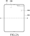
- FIG. 2A is a view illustrating an example of an electronic device 200 including a plurality of areas (e.g., a waterproof area 201 and a non-waterproof area 202) according to an embodiment of the disclosure.
- FIG. 2B is a view illustrating an example in which an electrical connecting member (e.g., a flexible printed circuit board (FPCB) 230 (or flexible circuit board)) is disposed in a plurality of areas (e.g., a waterproof area 201 and a non-waterproof area 202) according to an embodiment of the disclosure.
- FPCB flexible printed circuit board
- an electronic device 200 may include a front surface 210A, a rear surface 210B, and a side surface 210C surrounding a space between the front surface 210A and the rear surface 210B.
- the at least one structure may be included in an inner space defined by the front surface 210A, the rear surface 210B, and the side surface 210C.
- the at least one structure may include a housing 220.
- the housing 220 may include a single housing or a plurality of housings that may be coupled to each other (e.g., rotatably coupled) (e.g., housing structures described below in connection with FIGS.
- the at least one structure may replace at least some of the surfaces (e.g., upper surface, lower surface, side surface) of the housing 220 or other structures (e.g., a rear cover 221 and/or hinge cover 222, bracket 223 described below) assembled. Further, without limited to the described shapes or combination, it may also be implemented as a combination and/or coupling of structures or in other shapes.
- the housing 220 may be a structure configured by coupling the rear cover 221, the hinge cover 222, and the bracket 223 to be described below.
- FIG. 2B shows an example of a portion of the cross section taken along line A-A'. Referring to FIG.
- the rear cover 221 may be configured as a lower portion of the housing 220
- the hinge cover 222 may be configured as at least a portion of a side portion of the housing 220
- the bracket 223 may be configured as an upper portion of the housing 220.
- the remaining side surface 210C portions may be formed by the outer wall of the housing 220.
- an inner space 201 e.g., a waterproof area described below
- the lower surface 220A (or inner surface) e.g., the lower surface of the bracket 223) of the upper portion of the housing 220 and the upper surface 220B (or inner surface) (e.g., the upper surface of the rear cover 221) of the lower portion of the housing 220.
- portions (e.g., the upper portion, side portion, and lower portion) of the housing 220 described below may mean portions (e.g., the rear cover 221, the hinge cover 222, or the bracket 223) constituting the housing 220 or portions of the single housing 220.
- the space (e.g., the inner space defined by the front surface 210A, the rear surface 210B, and the side surface 210C) formed inside the electronic device 200 may include a plurality of areas 201 and 202 (or a plurality of spaces) and may include an electrical connecting member (e.g., the flexible printed circuit board (FPCB) 230 described below) disposed in each area 201 and 202 (or spaces).
- FPCB flexible printed circuit board
- the space formed inside the electronic device 200 may include a first area 201 (or space) (e.g., waterproof area) and a second area 202 (or space) (e.g., non-waterproof area) and may include an electrical connecting member disposed in each area (e.g., the first area 201 and the second area 202).
- a first area 201 or space
- a second area 202 or space
- an electrical connecting member disposed in each area (e.g., the first area 201 and the second area 202).
- various types of electric components may be disposed inside the electronic device 200, and the electric components may include the components of the electronic device 200 described in connection with FIG. 1 .
- examples of a plurality of areas e.g., the waterproof area 201 and the non-waterproof area 202 formed inside the electronic device 200 and an electrical connecting member (e.g., the flexible printed circuit board 230) are described.
- the plurality of areas 201 and 202 (e.g., the waterproof area 201 and the non-waterproof area 202) of the electronic device 200 may be implemented by at least a portion (e.g., a wall 222 of an upper portion (or bracket 223), lower portion (or rear cover 221), and/or side portion (or hinge structure (not shown)) of the housing 220) of at least one structure disposed inside the electronic device 200.
- a portion e.g., a wall 222 of an upper portion (or bracket 223), lower portion (or rear cover 221), and/or side portion (or hinge structure (not shown) of the housing 220.
- the structure may be a wall 222 forming the upper portion (or bracket 223), lower portion (or rear cover 221), and/or side portion (or hinge structure (not shown)) of the housing 220 positioned inside the electronic device 200, and the wall of the housing 220 may include at least one through hole 203 (or opening) (or the through hole 203 may be formed in the wall of the housing 220).
- the plurality of areas 201 and 202 may be implemented (or formed).
- a space surrounded by the lower surface 220A (or inner surface) of the upper portion (or lower surface of the bracket 223) of the housing 220, the upper surface 220B (or inner surface) of the lower portion (or the upper surface of the rear cover 221) of the housing 220, and/or the inner surface 220 of the side portion of the housing 220, of the inner space of the electronic device 200, may be the first area 201 (e.g., waterproof area).
- a space formed outward of the outer surface 220A (or upper surface) of the upper portion (or bracket 223) of the housing, of the inner space of the electronic device 200 may be the second area 202 (e.g., non-waterproof area) (or a space between the outer surface 220A of the upper portion of the housing 220 and the upper surface 210A of the electronic device 200 (or space between it and the lower surface 220B of the display panel (not shown) disposed on the upper surface 210).
- the second area 202 e.g., non-waterproof area
- a through hole 203 may be formed in the wall of the housing 220 between the areas (e.g., the waterproof area 201 and the non-waterproof area 202), and the electrical connecting member (e.g., the flexible printed circuit board 230) may be disposed in the areas (e.g., the waterproof area 201 and the non-waterproof area 202) through the through hole 203.
- a predetermined waterproofing member 231 may be disposed between the through hole 203 and the electrical connecting member (e.g., the flexible printed circuit board 230), filling the gap (e.g., through hole 203) through which a predetermined liquid may infiltrate to the waterproof area 201.
- the waterproof area 201 and the non-waterproof area 202 may be implemented by at least one barrier formed inside the electronic device 200, and the electrical connecting member (e.g., the flexible printed circuit board 230) may be disposed in the two areas through the through hole 203 (or opening) formed in the at least one barrier.
- the space surrounded by the barrier inside the electronic device 200 may be the waterproof area 201 (or space)
- the space implemented outside the at least one barrier from the waterproof area 201 may be the non-waterproof area 202 (or space).
- An example of a structure in which the plurality of areas 201 and 202 and the electrical connecting member formed in the inner space of the electronic device 200 are disposed is further described below in connection with FIGS. 5A , 5B , and 7A to 7C .
- the electrical connecting member may be implemented of a flexible material and may include at least one pattern or wire (e.g., a metal pattern or metal wire) for electrically connecting different electric components (e.g., printed circuit boards (PCBs)).
- the electrical connecting member may include a single printed circuit board (FPCB) 230 or several overlapping flexible printed circuit boards 230 but, without limited to those described, may include various types of electrical connecting members (e.g., wires or electrodes) for electrically connecting electric components.
- FPCB printed circuit board
- electrical connecting member may include various types of electrical connecting members (e.g., wires or electrodes) for electrically connecting electric components.
- reinforcement portion reinforcement portion 330 of FIGS.
- the at least one flexible printed circuit board 230 may pass through the through hole 203 which divides the waterproof area 201 and the non-waterproof area 202, and a portion connected to the specific portion 231B may be disposed in the non-waterproof area 202 while another portion (or one end 231A) may be disposed in the waterproof area 201.
- a predetermined waterproofing member 231 (or sealing member) may be provided to surround the specific portion 231B (hereinafter, reinforcement portion (reinforcement portion 330 of FIGS. 3A to 3F )).
- reinforcement portion reinforcement portion 330 of FIGS. 3A to 3F
- At least one flexible printed circuit board 300 as an example of an electrical connecting member included in the electronic device (e.g., the electronic device 200 of FIG. 2A ), is described.
- the flexible printed circuit board 300 may include a plurality of layers 301 and may include a connector portion 310 (i.e., 310a, and 310b), a wiring portion 320 (i.e., 320a, 320b, 320c, 320d, and 320e), a reinforcement portion 330 (i.e., 330a, and 330b), and a fixing portion 340 (i.e., 340a, and 340b).
- a connector portion 310 i.e., 310a, and 310b
- a wiring portion 320 i.e., 320a, 320b, 320c, 320d, and 320e
- a reinforcement portion 330 i.e., 330a, and 330b
- a fixing portion 340 i.e., 340a, and 340b
- the flexible printed circuit boards 300 may be electrically connected to each other through via holes formed in the flexible printed circuit boards 300.
- a specific transmission line (or conductive wire, conductive pattern, or conductive path) of a flexible printed circuit board 300 disposed on a specific layer e.g., a first layer
- a specific layer e.g., a first layer
- another layer e.g., a second layer
- the specific transmission line may jump and get around other transmission lines on the specific layer (e.g., the first layer).
- a connector portion 310 may be formed at an end portion forming each end (e.g., a first end and a second end) of the flexible printed circuit board 300.
- the connector portion 310 may include a first connector portion 310a formed at the first end and a second connector portion 310b formed at the second end.
- the connector portion 310 may be implemented to include an electrical connecting structure.
- the connector portion 310 may include a rigid portion formed at the end, and a pin 311 connected to an end of each of the transmission lines on at least one transmission layer may be disposed in the rigid portion, forming a predetermined connection end portion.
- connection end portion of the connector portion 310 is coupled to a connector of an electric component (e.g., a printed circuit board) described below, the electric component and the flexible printed circuit board 300 may be electrically connected to each other (e.g., the transmission line on the transmission layer is connected to the electric component).
- the connector portion 310 may be formed in an end portion of a specific flexible printed circuit board 300 (e.g., the lowermost flexible printed circuit board 300), or if the flexible printed circuit boards 300 are electrically separated, a connector portion 310 implemented to include the pins 311 formed in the end portion of each flexible printed circuit board 300 may be formed.
- the width in one direction (e.g., the Y-axis direction) of the connector portion 310 may be formed to be larger than the width of other portions (e.g., the wiring portion 320 and the reinforcement portion 330) of the flexible printed circuit board 300.
- the width of the connector portion 310 may be formed to be larger than the width w2 of the wiring portion 320.
- the width of the connector portion 310 may be larger than the width w1 of the reinforcement portion 330.
- a first difference between the width s2 of the connector portion 310 and the width w1 of the reinforcement portion 330 may be smaller than a second difference between the width of the connector portion 310 and the width of the wiring portion 320.
- the width of the through hole 203 may be required to be larger than the width of the connector portion 310. Accordingly, the width of the through hole 203 may be implemented to increase in proportion to the width of the connector portion 310. Alternatively, as opposed, the width of the connector portion 310 may be implemented in proportion to the width of the through hole 203.
- An example of the wiring portion 320 and the reinforcement portion 330 according to various embodiments is described below.
- the reinforcement portion 330 may be formed at a portion of the flexible printed circuit board 300 which passes through the through hole (e.g., the through hole 203 of FIG. 2B ) (or opening).
- the flexible printed circuit board 300 is disposed in a plurality of areas (e.g., a waterproof area (e.g., the waterproof area 201 of FIG. 2B ) and a non-waterproof area (e.g., the non-waterproof area 202 of FIG. 2B )) of the inner space of the electronic device (e.g., the electronic device 200 of FIG. 2A ) through the through hole (e.g., the through hole 203 of FIG.
- waterproofing member 350 An example of the waterproofing member 350 according to various embodiments is described.
- the reinforcement portion 330 may be implemented to correspond to the area (e.g., the lengths in the Y-axis and Z-axis directions) of the reinforcement portion 330 so that the reinforcement portion 330 may be inserted into the through hole of the body portion 351.
- the outer surface of the reinforcement portion 330 may contact the inner surface of the through hole (e.g., the through hole 203 of FIG. 2B ), reducing the inflow of the fluid.
- the coupling portions 352 are implemented to have a predetermined step C from the body portion 351, the waterproofing member 350, when inserted into the through hole (e.g., the through hole 203 of FIG.
- the housing may be tightly coupled by the contact between the side surfaces of the coupling portions 352 and the inner surface of the through hole (e.g., the through hole 203 of FIG. 2B ).
- Recesses into which the coupling portions 352 may be fitted may be formed in the inner surface of the through hole 203, and the coupling portions 352 may be fitted into the recesses.
- the coupling portions 352 may also be implemented in a shape (e.g., oval or rectangular) corresponding to the body portion 351. However, as described above, the area of the coupling portion 352 may be implemented to be larger than the area of the body portion 351 to have the step c. For example, referring to FIGS.
- the reinforcement portion 330 may include bonding members 332 (or adhesive members) between the plurality of layers 301.
- the bonding members 332 may be implemented as predetermined layers disposed between the plurality of layers 301 and may be implemented of various types of polymers capable of reducing separation (or detachment) between the layers due to external shocks.
- the bonding member 332 may include a tape implemented as a predetermined adhesive material (e.g., a high-modulus substance, such as epoxy).
- the bonding members 332 may include a bonding material that fills the gaps between the plurality of layers 301 while forming predetermined layers.
- the bonding members 332 may be formed between the plurality of layers 301 by a thermocompression process.
- the reinforcement portion 330 including the bonding members 332 between the plurality of layers 301, may be rendered to have higher rigidity than the other portions (e.g., the wiring portion 320) by the thermocompression (or may be rigidly implemented).
- the above-described dummy area e.g., the second area Y2
- the reinforcement portion 330 may further include rigid layers 333 on the uppermost layer and under the lowermost layer of the plurality of layers 301.
- the bonding member 33 may be disposed between the rigid layer 333 and the uppermost or lowermost layer of the plurality of layers 301, the rigid layer 333 and the uppermost or lowermost layer of the plurality of layers 301 may be attached to each other.
- the thickness of the reinforcement portion 330 e.g., the length in the Z-axis direction
- Z1 may be formed to be larger than the thickness Z2 of the wiring portion 320. Since no bonding member 332 is formed in the plurality of layers 301 of the wiring portion 320, a gap may be formed between the plurality of layers 301 of the wiring portion 320 adjacent to the reinforcement portion 330.
- the length X1 in the length direction of the flexible printed circuit board 300 of the reinforcement portion 330 may be implemented to be larger than the length X2 of the waterproofing member 350 (e.g., the length in the X-axis direction) so that the gap is formed outside the waterproofing member 350.
- the length x1 in the length direction of the flexible printed circuit board 300 of the reinforcement portion 330 may be implemented to be larger than the length x2 of the waterproofing member 350 (e.g., the length in the X-axis direction).
- the portion 321 where the reinforcement portion 330 and the wiring portion 320 are connected may be formed with a predetermined curvature.
- the width of the reinforcement portion 330 e.g., the length in the Y-axis direction
- the portion 321 where the predetermined wiring portion 320 is connected to the reinforcement portion 330 may be implemented to have a predetermined curvature inward so as to gradually reduce the difference in width between the reinforcement portion 330 and the wiring portion 320.
- the portion 321 where the wiring portion 320 is connected to the reinforcement portion 330 may be implemented so that its width (e.g., the length in the Y-axis direction) gradually increases as it approaches the reinforcement portion 330.
- the fixing portion 340 may be rigidly implemented.
- a fixing member 341 including a through hole (e.g., the through hole 203 of FIG. 2B ) or an undercut structure may be disposed in at least a partial area of the rigidly implemented fixing portion 340 and may be coupled to the housing based on the through hole or undercut structure.
- the fixing portion 340 may be attached to the housing by a tape while being disposed in the housing.
- the flexible printed circuit board 300 may be implemented in various shapes.
- at least two or more connector portions 310, at least two or more wiring portions 320, and/or at least two or more reinforcement portions 330 may be included in a portion of the flexible printed circuit board 300.
- the through hole e.g., the through hole 203 of FIG. 2B
- the length in one direction (e.g., the Y-axis direction) of the reinforcement portion 330 may be implemented to be larger than the length W5 in one direction (e.g., the Y-axis direction) of the wiring portion 320 between the coupling portions 310 and the reinforcement portion 330 and the length W4 in one direction (e.g., the Y-axis direction) of the wiring portion 320 between the reinforcement portion 330 and the fixing portion 340.
- the foregoing description may be applied to the connector portion 310, the wiring portion 320, the reinforcement portion 330, and the fixing portion 340, and no duplicate description is given.
- an example of the flexible printed circuit board 300 including the above-described plurality of connector portions is further described.
- the foldable housing 405 may include a first housing structure 410, a second housing structure 420 including a sensor area 424, a first rear cover 480, a second rear cover 490, a hinge cover 430 (e.g., a first hinge cover 431 and a second hinge cover 432), and brackets (e.g., a first bracket 411 and a second bracket 412) described below in connection with FIG. 3C .
- the foldable housing 405 of the electronic device 400 are not limited to the shape and coupling shown but may rather be implemented in other shapes or via a combination and/or coupling of other components.
- first housing structure 410, the first rear cover 480, the first hinge cover 431, and the first bracket 411 may be integrally formed or assembled
- second housing structure 420, the second rear cover 490, the second hinge cover 432, and the second bracket 412 may be integrally formed or assembled.
- inner spaces e.g., waterproof areas 201
- the housing structures e.g., the first housing structure 410 and the second housing structure 420
- the rear covers e.g., the first rear cover 480 and the second rear cover 490
- the brackets e.g., the first bracket 411 and the second bracket 412
- at least one electric component e.g., the printed circuit boards 530a and 530b of FIG.
- Through holes 510 and 520 may be formed in at least part of the housing structures (e.g., the first housing structure 410 and the second housing structure 420) (or at least part of the brackets (e.g., the first bracket 411 and the second bracket 412)) coupled to the housing structures (e.g., the first housing structure 410 and the second housing structure 420)), and the flexible printed circuit board (the flexible printed circuit board 300 described above in connection with FIG. 3A ) may be disposed through the through holes 510 and 520. Accordingly, the flexible printed circuit board (the flexible printed circuit board 300 described above in connection with FIG. 3A ) may be disposed in at least part of the housing structures (e.g., the first housing structure 410 and the second housing structure 420). An example in which the flexible printed circuit board (the flexible printed circuit board 300 described above in connection with FIG. 3A ) is disposed is described below with reference to FIGS. 4A and 4B .
- the first housing structure 410 and the second housing structure 420 may be positioned on opposite sides of a folding axis (axis A), and they may be overall symmetrical in shape with each other with respect to the folding axis A. As set forth below, the first housing structure 410 and the second housing structure 420 may have different angles or distances formed therebetween depending on whether the electronic device 400 is in an unfolded, folded, or intermediate state. In the illustrated embodiment, the first housing structure 410 and the second housing structure 420 may be symmetrical in shape except that the second housing structure 520 further includes the sensor area 424 where various sensors are arranged, unlike the first housing structure 510.
- the first housing structure 410 and the second housing structure 420 together may form a recess to receive the display 401.
- the recess may have two or more different widths in the direction perpendicular to the folding axis A.
- the first portion 410a of the first housing structure 410 and the first portion 420a of the second housing structure 420 which are asymmetrical in shape to each other, may form the first width w1 of the recess
- the second portion 410b of the first housing structure 410 and the second portion 420b of the second housing structure 420 which are symmetrical in shape to each other, may form the second width w2 of the recess.
- the first portion 420a and second portion 420b of the second housing structure 420 may have different distances from the folding axis A.
- the width of the recess is not limited thereto.
- the recess may have a plurality of widths due to the shape of the sensor area 424 or the asymmetric portions of the first housing structure 410 and the second housing structure 420.
- the front surface of the electronic device 400 may include the display 401 and a partial area of the first housing structure 410 and a partial area of the second housing structure 420, which are adjacent to the display 401.
- the rear surface of the electronic device 400 may include the first rear cover 480, a partial area of the first housing structure 410, which is adjacent to the first rear cover 480, the second rear cover 490, and a partial area of the second housing structure 420, which is adjacent to the second rear cover 490.
- the display 401 may mean a display at least a portion of which may be transformed to be flat or curved.
- the display 401 may include a folding area 404, a first area 402 disposed on one side of the folding area 404 (e.g., the left side of the folding area 404 of FIG. 4A ), and a second area 403 disposed on the opposite side of the folding area 404 (e.g., the right side of the folding area 103 of FIG. 4A ).
- the first area 402 and the second area 403 may be overall symmetrical in shape with respect to the folding area 404. However, unlike the first area 402, the second area 403 may include a notch depending on the presence of the sensor area 424, but the rest may be symmetrical in shape with the first area 402. In other words, the first area 402 and the second area 403 may include symmetrical portions and asymmetrical portions.
- first housing structure 410 and the second housing structure 420 Described below are the operation of the first housing structure 410 and the second housing structure 420 and each area of the display 401 depending on the state (e.g., the unfolded state (flat state) and folded state) of the electronic device 400.
- state e.g., the unfolded state (flat state) and folded state
- the first housing structure 410 and the second housing structure 420 may be angled at 180 degrees therebetween, facing in the same direction.
- the surface of the first area 402 and the surface of the second area 403 of the display 401 may be angled at 180 degrees therebetween while facing in the same direction (e.g., forward of the front surface of the electronic device).
- the folding area 404 may be coplanar with the first area 402 and the second area 403.
- the first housing structure 410 and the second housing structure 420 may be disposed to face each other.
- the surface of the first area 402 and the surface of the second area 403 of the display 401 may be angled at a small angle (e.g., ranging from 0 degrees to 10 degrees) therebetween while facing each other.
- At least a portion of the folding area 404 may have a curved surface with a predetermined curvature.
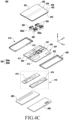
- FIG. 4C is an exploded perspective view illustrating an electronic device according to an embodiment of the disclosure.
- an electronic device 400 may include a display unit 406, a bracket assembly 407, a board unit 415 (e.g., the printed circuit board 530a or 530b of FIGS. 5A to 5C ), a first housing structure 410, a second housing structure 420, flexible printed circuit boards (the flexible printed circuit board 300 described above in connection with FIGS. 3A to 3E ), a first rear cover 480, and a second rear cover 490.
- the display unit 406 may be referred to as a display module or display assembly.
- the display unit 406 may include a display 401 and one or more plates or layers 440 on which the display 401 is seated.
- the plate 440 may be disposed between the display panel 401 and the bracket assembly 407.
- the display 401 may be disposed on at least a portion of one surface (e.g., an upper surface of FIG. 4C ) of the plate 440.
- the plate 440 may be formed in a shape corresponding to the display 401.
- a portion of the plate 440 may be formed in a shape corresponding to the notch 409 of the display 401.
- the bracket assembly 407 may include a first bracket 411, a second bracket 412, a hinge structure (not shown) disposed between the first bracket 411 and the second bracket 412, a hinge cover 430 covering the hinge structure when the hinge structure is viewed from the outside, and flexible printed circuit boards 300 crossing the first bracket 411 and the second bracket 412.
- the flexible printed circuit boards 300 may be disposed in a direction (e.g., the x-axis direction) crossing the first bracket 411 and the second bracket 412.
- the flexible printed circuit boards 300 may be disposed in a direction (e.g., the x-axis direction) perpendicular to the folding axis (e.g., the folding axis A of FIG.
- the flexible printed circuit boards 300 may be provided as a plurality of through holes are formed in each of the housing structures 410 and 420.
- the flexible printed circuit boards 300 may be disposed on the hinge cover 430 (or the hinge structure (not shown) wrapped around the hinge cover 430).
- the wiring portion 320 of each of the flexible printed circuit boards 300 may be bent and disposed on part of the brackets 411 and 412 or the hinge cover 430 (or hinge structure (not shown)).
- a reinforcement portion 330 connected to the wiring portion 320 of each of the flexible printed circuit boards (the flexible printed circuit boards 330 described above in connection with FIGS.
- 3A to 3F may be disposed through the through hole formed in each of the housing structures (e.g., the first housing structure 410 and the second housing structure 420) (or brackets (e.g., the first bracket 411 and the second bracket 412)).
- the flexible printed circuit board 300 is disposed is further described below with reference to FIGS. 5A to 5C .
- the bracket assembly 407 may be disposed between the plate 440 and the circuit board unit 415.
- the first bracket 411 may be disposed between the first area 402 of the display 401 and a first circuit board 413.
- the second bracket 412 may be disposed between the second area 403 of the display 401 and a second circuit board 414.
- the circuit board unit 415 may include the first circuit board 413 disposed on the first bracket 411 and the second circuit board 414 disposed on the second bracket 412.
- the first circuit board 413 and the second circuit board 414 may be disposed inside a space formed by the bracket assembly 407, the first housing structure 410, the second housing structure 420, the first rear cover 480, and the second rear cover 490.
- Components for implementing various functions of the electronic device 400 may be disposed on the first circuit board 413 and the second circuit board 414.
- the first housing structure 410 and the second housing structure 420 may be assembled together to be coupled to both sides of the bracket assembly 407, with the display unit 406 coupled to the bracket assembly 407. As described below, the first housing structure 410 and the third housing structure 420 may slide from both sides of the bracket assembly 407 and fit with the bracket assembly 407.
- the first housing structure 410 may include a first rotation supporting surface 412
- the second housing structure 420 may include a second rotation supporting surface 422 corresponding to the first rotation supporting surface 412.
- the first rotation supporting surface 412 and the second rotation supporting surface 422 may include a curved surface corresponding to a curved surface included in the hinge cover 430.
- the first rotation supporting surface 412 and the second rotation supporting surface 422, in the unfolded state of the electronic device 400 may cover the hinge cover 430, allowing the hinge cover 430 to be not or minimally exposed to the rear surface of the electronic device 400.
- the first rotation supporting surface 412 and the second rotation supporting surface 422, in the folded state of the electronic device 400 may rotate along the curved surface included in the hinge cover 430, allowing the hinge cover 430 to be maximally exposed to the rear surface of the electronic device 400.
- FIGS. 5A to 5C an example of a flexible printed circuit board disposed inside the electronic device 400 is described with reference to FIGS. 5A to 5C .
- FIG. 5A is a view illustrating an example of an arrangement relationship of internal components of an electronic device 400 in an unfolded state according to an embodiment of the disclosure.
- FIG. 5B is a view illustrating an example of an arrangement relationship of internal components of an electronic device 400 in an unfolded state, as viewed from a side surface, according to an embodiment of the disclosure.
- FIG. 5C is a view illustrating an example of a flexible printed circuit board passing through a through hole formed in a housing structure (or bracket) of an electronic device 400 in an unfolded state according to an embodiment of the disclosure.
- FIG. 5A illustrates a state in which the hinge structure, the display 401, and the bezel are removed from the electronic device 400.
- the electronic device 400 may include a foldable housing including a folding area H in which the electronic device 400 is substantially folded around a folding axis, and the foldable housing may include a first housing structure 410 and a second housing structure 420.
- each of the first housing structure 410 and the second housing structure 420 may be integrally formed or assembled with rear covers (e.g., the first rear cover 480 and the second rear cover 490), hinge covers (e.g., the first hinge cover 431 and the second hinge cover 432), and brackets (e.g., the first bracket 411 and the second bracket 412).
- FIG. 5B shows a side surface of FIG. 5A .
- inner spaces 201 may be formed by the housing structures (e.g., the first housing structure 410 and the second housing structure 420), the rear covers (e.g., the first rear cover 480 and the second rear cover 490), the hinge covers (e.g., the first hinge cover 431 and the second hinge cover 432), and the brackets (e.g., the first bracket 411 and the second bracket 412), and the inner spaces 201 may be defined as waterproof areas.
- the housing structures e.g., the first housing structure 410 and the second housing structure 420
- the rear covers e.g., the first rear cover 480 and the second rear cover 490
- the hinge covers e.g., the first hinge cover 431 and the second hinge cover 432
- brackets e.g., the first bracket 411 and the second bracket 412
- the waterproof areas 201 may be formed which are surrounded by the lower surface of the brackets (e.g., the first bracket 411 and the second bracket 412), the upper surface of the rear covers (e.g., the first rear cover 480 and the second rear cover 490) facing it, and the hinge covers (e.g., the first hinge cover 431 and the second hinge cover 432).
- Each of the waterproof areas 201 may be formed corresponding to each of the housing structures (e.g., the first housing structure 410 and the second housing structure 420).
- Through holes 510 and 520 may be formed in at least part (e.g., the brackets 411 and 412) of the respective upper portions of the housing structures (e.g., the first housing structure 410 and the second housing structure 420).
- a first through hole 510 (or opening) may be prepared to penetrate the first bracket 411 from the top to bottom, and a second through hole 520 may be prepared to penetrate the second bracket 412 from the top to bottom.
- the through holes 510 and 520 may be closed by the waterproofing member 350 provided in a portion (e.g., the reinforcement portion 330) of the flexible printed circuit board 300.
- the outside area of the through holes 510 and 520 may be defined as a non-waterproof area 202.
- a space 201 formed between the upper surface of the hinge covers 431 and 432 and the lower surface of the flexible display 401 (or the plate on which the flexible display 401 is disposed) facing the upper surface of the brackets 411 and 412 may be the waterproof area.
- the flexible printed circuit boards 300 may be disposed, on the components of the electronic device 400, to cross the two housing structures (e.g., the first housing structure 410 and the second housing structure 420).
- the flexible printed circuit boards 300 e.g., the first flexible printed circuit board 300a and the second flexible printed circuit board 300b
- the flexible printed circuit boards 300 may be disposed in the waterproof areas 201 and the non-waterproof areas 202.
- a portion (e.g., the wiring portion 320) of each of the flexible printed circuit boards 300 may be disposed in the non-waterproof area 202.
- the wiring portion 320 connected between the respective reinforcement portions 330 of the flexible printed circuit boards 300 may be disposed to overlap the upper surface of the hinge covers 431 and 432 (e.g., the first hinge cover 431 and the second hinge cover 432) and part of the brackets 411 and 412. Referring to FIG.
- first portions b1 of the wiring portion 320 connected between the respective reinforcement portions 330 of the flexible printed circuit boards 300 may be bent away from the hinge covers 431 and 432 or the rear covers 480 and 490, and second portions b2 may be bent toward the hinge covers 431 and 432 or the rear covers 480 and 490.
- the lower surface of a third portion b3 between the second portions b2 of the wiring portion 320 may be disposed to face the upper surface of the hinge covers 431 and 432 (or hinge structure (not shown)), and the lower surface of a fourth portion b4 connected between each of the second portions b2 of the wiring portion 320 and each of the first portions b 1 may be disposed to face the bent surface of each of the hinge covers 431 and 432.
- the lower surface of a fifth portion b5 of the wiring portion 320 connected with each of the first portions b1 of the wiring portion 320 and each of the reinforcement portions 330 may be disposed to face the upper surface of at least part of each of the brackets 411 and 412. As shown in FIG.
- a fixing member may further be disposed between the lower surface of the fifth portion b5 of the wiring portion 320 and the upper surface of at least part of each of the brackets 411 and 412, to support the fifth portion b5 of the wiring portion 320.
- the fifth portion b5 may include the above-described fixing portion 340.
- the fixing portion 340 may be disposed on the fixing member disposed on the upper surface of at least part of each of the brackets 411 and 412 and, as the holes of the fixing portion 340 and the holes of the fixing member are coupled, the flexible printed circuit board 300 may be firmly supported.
- FIG. 5C is an enlarged view of a structure in which one reinforcement portion 330 of one flexible printed circuit board 300 passes through one through hole 510 or 520 formed in part of one housing structure (e.g., the first housing structure 410 (or one bracket (e.g., the first bracket 411))).
- one housing structure e.g., the first housing structure 410 (or one bracket (e.g., the first bracket 411)
- the width c1 of the reinforcement portion 330 may be formed to be larger than the width c3 of the wiring portion 320 connected to the reinforcement portion 330.
- the plurality of layers 301 of the reinforcement portion 330 may be bonded by the bonding member 332 so that the reinforcement portion 330 may have rigidity. Accordingly, the rigidity of the reinforcement portion 330 may be enhanced, and further enhanced rigidity may be provided from the reinforcement portion 330 to the waterproofing member 350. Accordingly, the waterproofing member 350 may be robust against external force.
- end portions e.g., a first end portion and a second end portion
- the wiring portion 320 extending from the reinforcement portion 330 of each of the flexible printed circuit boards 300 may be disposed in the non-waterproof area 202.
- the end portion of each of the flexible printed circuit boards 300 may be electrically connected to at least one electric component disposed in the non-waterproof area 202.
- the at least one electric component may include a printed circuit board (PCB) 530a and 530b.
- PCB printed circuit board
- the electronic device 400 may adopt a connector-to-connector (C-to-C) type (C2C type) electrical connecting structure (or connector structure) for connecting two different connectors C, as well as various types of connecting structures.
- C-to-C connector-to-connector
- the connector portions 310 formed at the end portions (e.g., the first end portion and the second end portion) of the flexible printed circuit boards 300 may be electrically connected to the respective connectors of the printed circuit boards 530a and 530b disposed in the waterproof areas 201. Accordingly, the electric components (e.g., the printed circuit boards 530a and 530b) disposed in the waterproof areas 201 through the flexible printed circuit board 300 may be electrically connected.
- FIG. 6A is a view illustrating an unfolded state of an electronic device 600 with respect to a specific folding direction according to an embodiment of the disclosure.
- inner spaces may be formed by the pair of housing structures (e.g., the first housing structure 610 and the second housing structure 620), the hinge structure 660 (or hinge cover (not shown)), the rear covers 680 (e.g., the first rear cover 681 and the second rear cover 682), and the bracket assemblies (e.g., the first bracket assembly 613 and the second bracket assembly 624), and at least one electric component (e.g., the printed circuit board 530) may be disposed in the inner spaces.
- the pair of housing structures e.g., the first housing structure 610 and the second housing structure 620
- the hinge structure 660 or hinge cover (not shown)
- the rear covers 680 e.g., the first rear cover 681 and the second rear cover 682
- the bracket assemblies e.g., the first bracket assembly 613 and the second bracket assembly 624
- at least one electric component e.g., the printed circuit board 530
- an inner space (e.g., non-waterproof area 202) separated from the above-described waterproof area 201 may also be formed between at least part of the housing structures (e.g., the first housing structure 310 and the second housing structure 320) (e.g., at least part of the bracket assemblies coupled to the housing structures) and the flexible display 630 (or a plate on which the flexible display 630 is disposed).
- the housing structures e.g., the first housing structure 310 and the second housing structure 320
- the flexible display 630 e.g., a plate on which the flexible display 630 is disposed
- first housing structure 610 and the second housing structure 620 may be disposed on two opposite sides of folding axis B (e.g., a horizontal folding axis).
- the first housing structure 610 may include an area in which a camera 614 and various sensors 615 are disposed unlike the second housing structure 620 but, in the other areas, may be symmetric in shape.
- the area in which the camera 614 and various sensors 615 are disposed may be additionally disposed in, or replaced with, at least a partial area of the second housing structure 620.
- At least part of the camera 614 or various sensors 615 may be disposed in at least a partial area of the first housing 610, and the remaining part may be disposed in at least a partial area of the second housing structure 620.
- the second housing structure 620 may include a third surface 621 disposed to face the front surface of the electronic device 600, a fourth surface 622 facing in the direction opposite to the third surface 621, and a second side member 623 surrounding at least part of a space between the third surface 621 and the fourth surface 622.
- the second surface 621 may be replaced by, or integrally assembled with, the second bracket assembly described below.
- the camera 614 may be visually exposed on the front surface of the electronic device 600 through an opening provided in one corner of the first housing structure 610.
- the sensors 615 may include at least one of a proximity sensor, an illuminance sensor, an iris recognition sensor, an ultrasonic sensor, and an indicator.
- the sensors 615 may be exposed on the front surface of the electronic device 600 through an opening provided in one corner of the first housing structure 610 or may be disposed at the lower end of at least a partial area of the display 401.
- the electronic device 600 may include a first motion sensor 651 and a magnetic body (e.g., a magnet) 652 disposed on at least a portion of the first housing structure 610.
- the first motion sensor 651 may be configured as a combination of at least two of an acceleration sensor, an angular velocity sensor (e.g., a gyro sensor), or a geomagnetic sensor.
- the electronic device 600 may detect the pose and motion (gesture) of the first housing structure 610 through the first motion sensor 651.
- the posture of the first housing structure 610 may be detected based on the acceleration sensor of the first motion sensor 651, and the motion of the first housing structure 610 may be detected based on the angular velocity sensor of the first motion sensor 651.
- the magnetic body 652 may be disposed on at least a portion of the first housing structure 610 adjacent to the hinge structure 660.
- the electronic device 600 may include a second motion sensor 653 and a magnetic force sensor module 654 disposed on at least a portion of the second housing structure 620.
- the second motion sensor 653 may be configured as a combination of at least two of an acceleration sensor, an angular velocity sensor (e.g., a gyro sensor), or a geomagnetic sensor.
- the electronic device 600 may detect the posture of the second housing structure 620 through the acceleration sensor of the second motion sensor 653 and may detect the movement of the second housing structure 620 through the angular velocity sensor of the second motion sensor 653.
- the magnetic force sensor module 654 may be disposed on at least a portion of the second housing structure 620 adjacent to the hinge structure 660.
- the magnetic body 652 of the first housing structure 610 and the magnetic force sensor module 654 of the second housing structure 620 may be disposed to at least partially face each other in the folded state of the electronic device 600 as shown in FIG. 6B .
- FIG. 6B is a view illustrating a folded state of an electronic device 600 according to an embodiment of the disclosure.
- an electronic device 600 may include a pair of housing structures 610 and 620 (e.g., foldable housing structures) pivotably coupled to each other about folding axis B through a hinge structure 660 to be folded on each other and a display 630 (e.g., a flexible display or foldable display) disposed in a space formed by the pair of housing structures 610 and 620.
- a pair of housing structures 610 and 620 e.g., foldable housing structures
- a display 630 e.g., a flexible display or foldable display
- the senor may include a rear camera device 672 and/or a proximity sensor 474. According to an embodiment, at least a portion of a sub display 655 may be visually exposed through the rear surface 612 of the first housing structure 610.
- one or more components may be arranged or visually exposed on/through the rear surface of the electronic device 600.
- one or more components or sensors may be visually exposed through the rear surface (second surface) 612 of the first housing structure 610.
- the sensor may include a rear camera device 672 and/or a proximity sensor 474.
- at least a portion of a sub display 655 may be visually exposed through the rear surface 612 of the first housing structure 610.
- FIG. 6C is an exploded perspective view illustrating an electronic device 600 according to an embodiment of the disclosure.
- the display 630 may be exposed through a majority portion of the front plate 630a.
- the shape of the display 630 may be formed to be substantially the same as the shape of the periphery of the front plate 630a.
- the foldable housing may include a first housing 610 and a second housing 620 (e.g., the first housing structure 610 and the second housing structure 620 of FIG. 6A ).
- the first housing 610 may include a first surface 611a and a second surface 611b facing in a direction opposite to the first surface 611a.
- the second housing 620 may include a third surface 622a and a fifth surface 622b facing in a direction opposite to the third surface 622a.
- the foldable housing may additionally or alternatively include bracket assemblies (e.g., the first bracket assembly 613 and the second bracket assembly 624), a hinge structure 660 (or a hinge cover (not shown)), and rear covers 680 (e.g., the first rear cover 681 and the second rear cover 682).
- the bracket assemblies may include a first bracket assembly 613 disposed on the first housing structure 610 to form the first surface 611a and a second bracket assembly 624 disposed on the second housing structure 620 to form the third surface 620a.
- At least part of the bracket assemblies may serve as a plate for supporting the housing structure 640 (e.g., the first hinge structure and the second hinge structure).
- the first hinge structure may be coupled to the first housing structure 610 to form one side surface of the first housing structure
- the second hinge structure may be coupled to the second housing structure 620 to form one side surface of the second housing structure.
- the first rear cover 681 may be coupled to the first housing structure 610 to form a lower surface of the first housing structure
- the second rear cover 682 may be coupled to the second housing structure 620 to form a lower surface of the second housing structure 620.
- inner spaces may be formed by the pair of housing structures (e.g., the first housing structure 610 and the second housing structure 620), a housing structure 660 (or hinge cover (not shown)), rear covers 680 (e.g., a first rear cover 681 and a second rear cover 682), and bracket assemblies (e.g., a first bracket assembly 613 and a second bracket assembly 624).
- housing structures e.g., the first housing structure 610 and the second housing structure 620
- a housing structure 660 or hinge cover (not shown)
- rear covers 680 e.g., a first rear cover 681 and a second rear cover 682
- bracket assemblies e.g., a first bracket assembly 613 and a second bracket assembly 624.
- the flexible printed circuit board 300 may be disposed on at least a portion of the foldable housing 405.
- the flexible printed circuit board 300 may be disposed on the hinge structure 660 (or the hinge cover (not shown)).
- the wiring portion 320 of each of the flexible printed circuit boards 300 may be bent and disposed on the hinge structure 660, a portion 625 of the bracket assembly (e.g., the first bracket assembly 613 and the second bracket assembly 624) supporting the hinge structure 660, and another portion of the bracket assembly (e.g., the first bracket assembly 613 and the second bracket assembly 624) connected to the portion 625 of the bracket assembly.
- each reinforcement portion 330 connected to the wiring portion 320 of the flexible printed circuit board 300 may be disposed to pass through the through hole 710 and 720 formed in each of the housing structures (e.g., the first housing structure 310 and the second housing structure 320) (or the bracket assemblies (e.g., the first bracket assembly 613 and the second bracket assembly 624)).
- the flexible printed circuit board 300 is implemented so that a plurality of wiring portions 320 (e.g., two wiring portions) extend from the reinforcement portion 330.
- the other portions may be implemented as described above in connection with FIGS. 3A to 3F , and thus, no duplicate description is given.
- various electric components may be disposed on the printed circuit board 650.
- a processor e.g., the processor 120 of FIG. 1
- a memory e.g., the memory 130 of FIG. 1
- an interface e.g., the interface 177 of FIG. 1
- the processor may include one or more of, e.g., a central processing unit, an application processor, a graphic processing device, an image signal processing, a sensor hub processor, or a communication processor.
- the memory may include, e.g., a volatile or non-volatile memory.
- the interface may include, e.g., a high definition multimedia interface (HDMI), a universal serial bus (USB) interface, a secure digital (SD) card interface, and/or an audio interface.
- HDMI high definition multimedia interface
- USB universal serial bus
- SD secure digital
- the interface may electrically or physically connect, e.g., the electronic device 600 with an external electronic device and may include a USB connector, an SD card/multimedia card (MMC) connector, or an audio connector.
- MMC multimedia card
- the hinge structure 640 may be a component for supporting the foldable housing 405 and/or bracket assembly to allow the foldable housing to rotate about the folding axis (e.g., A-A' of FIG. 2A ).
- the hinge structure 640 may include a first hinge structure 641 disposed on the side of the first printed circuit board 651 and a second hinge structure 642 disposed on the side of the second printed circuit board 652.
- the hinge structure 640 may be disposed between the first printed circuit board 651 and the second printed circuit board 652.
- the hinge structure 640 may be formed substantially integrally with the portion 625 including at least a portion of the first bracket assembly 613 and at least a portion of the second bracket assembly 624.
- the rear cover 680 may include a first rear cover 681 and a second rear cover 682.
- the rear cover 680 may be combined with the foldable housing to protect the above-described components (e.g., the printed circuit board 650, the battery, and the antenna module 670) disposed in the foldable housing 405.
- the rear cover 680 may be configured substantially integrally with the foldable housing 405.
- FIG. 7A illustrates a state in which the rear covers 680 are removed from the electronic device 600.
- the electronic device 600 may include a foldable housing including a folding area H in which the electronic device 600 is substantially folded around a folding axis, and the foldable housing may include a first housing structure 610 and a second housing structure 620.
- the wiring portion 320 of the flexible printed circuit board 300 may be disposed on a portion of the bracket assembly, and each reinforcing portion 330 connected to the wiring portion 320 passes through the through hole 710 and 720 formed in the housing structure (e.g., the first housing structure 610 and the second housing structure 620) (or the bracket assemblies (e.g., the first bracket assembly 613 and the second bracket assembly 624)). No duplicate description is given. Although not shown, similar to those described above in connection with FIG.
- the width of the waterproofing member 350 and the reinforcing portion 330 may be implemented as described above in connection with FIGS. 3A to 3F and FIGS. 5A to 5B , so that a duplicate description is omitted.
- a plurality of (e.g., two) wiring portions 320 may extend from the reinforcing portion 330, and connector portions 310 may be formed at the respective end portions of the wiring portions 320.
- Each of the formed connector portions 310 may be electrically connected to a respective one of the electrical components (e.g., a printed circuit board) provided in the waterproof area 201.
- the width a1 (e.g., the length in the Y-axis direction) of the two connector portions 310 may be implemented to be smaller than the width a2 (e.g., the length in the Y-axis direction) of the through hole 710 and may be implemented to be larger than or equal to the width a3 of the reinforcement portion 330.
- the width a3 of the reinforcement portion 330 may be larger than the width c1 of the reinforcement portion 330 described above in connection with FIGS. 5A and 5B .
- the width a3 of the reinforcement portion 330 of the flexible printed circuit board 300 may be implemented in proportion to the width a1 of the connector portion 310.
- the width a2 of the through hole 710 may increase in proportion to the width a1 of the connector portion 310. Since the width a3 of the reinforcement portion 330 needs to increase in proportion to the increase in the width a2 of the through hole 710, the width a3 of the reinforcement portion 330 may be implemented in proportion to the width a1 of the connector portions 310. For example, the width of the above-described dummy area (e.g., the second area Y2) may increase in proportion to the increase in the width a2 of the through hole 710. Accordingly, the width a3 of the reinforcement portion 330 of the flexible printed circuit board 300 implemented in FIGS.
- 7A and 7B may be formed to be relatively larger based on the fact that the width a1 of the connector portions 310 of the flexible printed circuit board 300 implemented in FIGS. 7A and 7B is formed to be larger than the width of the connector portion 310 of the flexible printed circuit board 300 described above in connection with FIGS. 5A and 5B .
- FIGS. 7A and 7B may be applied to what has been not described in connection with the examples of the connector portion 310, the wiring portion 320, the reinforcement portion 330, the fixing portion 340, and the waterproofing member 350. Thus, a further duplicate description is omitted.
- FIG. 8 is a view illustrating a process 800 of implementing a flexible printed circuit board 300 according to an embodiment of the disclosure.
- the process 800 of implementing the flexible printed circuit board 300 shown in FIG. 8 is an example and may include more or less operations than those shown. Further, it will be appreciated by one of ordinary skill in the art that the flexible printed circuit board 300 may be implemented without limited to the order of the implementing process.
- FIG. 9A is a view illustrating an example process of thermocompressing a bonding member 332 disposed between a plurality of layers 301 included in a reinforcement portion 330 of a flexible printed circuit board 300 according to an embodiment of the disclosure.
- FIG. 9B is a view illustrating an example in which a reinforcing member is disposed on a reinforcement portion 330 of a flexible printed circuit board 300 according to an embodiment of the disclosure.
- FIG. 9C is a view illustrating an example of a structure 910 for enhancing adhesivity between a reinforcement portion 320 of a flexible printed circuit board 300, a reinforcing member 920a and 920b, and a waterproofing member 350 according to an embodiment of the disclosure.
- FIG. 9A is a view illustrating an example process of thermocompressing a bonding member 332 disposed between a plurality of layers 301 included in a reinforcement portion 330 of a flexible printed circuit board 300 according to an embodiment of the disclosure.
- FIG. 9B is a view
- FIG. 9D is a view illustrating another example of a structure 910 for enhancing adhesivity between a reinforcement portion 320 of a flexible printed circuit board 300, a reinforcing member 920a and 920b, and a waterproofing member 350 according to an embodiment of the disclosure.
- FIG. 9E is a view illustrating another example of a structure 910 for enhancing adhesivity between a reinforcement portion 320 of a flexible printed circuit board 300, a reinforcing member 920a and 920b, and a waterproofing member 350 according to an embodiment of the disclosure.
- a reinforcing portion 330 may be formed on at least a portion of a flexible printed circuit board 300 in operation 801.
- the bonding member 332 e.g., a tape implemented as an adhesive material
- the plurality of layers 301 e.g., several flexible printed circuit boards 300 or a plurality of layers of a single flexible printed circuit board 300
- the through hole e.g., the through hole 203 of FIG. 2B , the through hole 510 or 520 of FIGS. 5A and 5B , or the through holes 710 and 720 of FIGS.
- a predetermined film 333 (or a rigid layer) may be disposed on each of the uppermost layer and lowermost layer of the plurality of layers 301, and a thermocompression process may be performed on the portion of the flexible printed circuit board 300.
- the reinforcement portion 330 may be formed by the thermocompression process, and the plurality of layers 301 of the reinforcement portion 330 may be bonded together by the bonding member 332 while the gaps between the plurality of layers 301 may be filled.
- the reinforcement portion 330 may be rendered to have higher rigidity than the rigidity of the other portions (e.g., the wiring portion 320) of the flexible printed circuit board 300 by the rigidity provided after the bonding member 332 is cured.
- the rest of the reinforcement portion 330 not described is the same as those described above in connection with FIGS. 3A to 3F and, thus, no duplicate description is given.
- a structure may be formed on the reinforcement portion 330 of the flexible printed circuit board 300 to secure attaching force (or bonding force).
- a structure for enhancing the bonding force between the waterproofing member 350 and the reinforcing member 920a and 920b described below may be formed.
- a predetermined hole structure 900a or an undercut structure 900b may be formed in the dummy area (e.g., the second area Y2) of the reinforcement portion 330.
- a predetermined hole structure or an undercut structure may also be formed in the area corresponding to the reinforcing member 920a and 920b described below.
- the waterproofing member 350 when the waterproofing member 350 is molded, with the reinforcing member 920a and 920b disposed on the reinforcement portion 330, a portion of the waterproofing member 350 may be molded in the predetermined hole structure 900a or undercut structure 900b.
- the bonding force between the reinforcement portion 330, the reinforcing member 920a and 920b, and the waterproofing member 350 may be enhanced based on the bonding force between the portion of the waterproofing member 350, inserted into the predetermined hole structure 900a or undercut structure 900b, and the reinforcing member 920a and 920b. Further, referring to FIG.
- a plurality of housing structures 900c and/or undercut structures 900d may be formed in the dummy area (e.g., the second area Y2) of the reinforcement portion 330.
- the reinforcing member 920a and 920b may be disposed on the reinforcement portion 330 of the flexible printed circuit board 300.
- a reinforcing member 920a and 920b implemented of a high-rigidity material, such as metal (STS) or epoxy sheet may be disposed on the reinforcement portion 330 to provide more secure rigidity.
- operation 803 may be performed earlier than operation 801.
- through holes or undercut structures may be formed which pass through the reinforcing member 920a and 920b and the reinforcement portion 330 from the top down, with the reinforcing member 920a and 920b disposed on the reinforcement portion 330.
- the waterproofing member 350 may be molded on the reinforcement portion 330 on which the reinforcing member 920a and 920b of the flexible printed circuit board 300 is disposed.
- a predetermined elastic member may be molded on the reinforcement portion 330 on which the reinforcing member 920a and 920b is disposed, thereby forming the waterproofing member 350.
- a predetermined elastic member may be molded on the reinforcement portion 330, with no reinforcing member 920a and 920b disposed, and the waterproofing member 350 may be formed.
- the waterproofing member 350 may be implemented as described above in connection with FIGS. 3A to 3F and, thus, no duplicate description is given.
- an electronic device e.g., the electronic device 200 of FIG. 2A
- a first housing e.g., the housing 220 of FIG. 2A , the housing structure 410 or 420 of FIGS. 4A to 4C , or the housing structure 610 or 620 of FIGS. 6A to 6C
- a first through hole e.g., the through hole 203 of FIG. 2B
- a flexible printed circuit board e.g., the flexible printed circuit board 300 of FIGS. 3A to 3F
- a plurality of layers e.g., the plurality of layers 301 of FIGS.
- a first portion e.g., the reinforcement portion 330 of FIGS. 3A to 3F
- the flexible printed circuit board e.g., the flexible printed circuit board 300 of FIGS. 3A to 3F
- a bonding member e.g., the bonding member 332 of FIGS. 3A to 3F
- the plurality of layers e.g., the plurality of layers 301 of FIGS. 3A to 3F
- a waterproofing member e.g., the waterproofing member 350 of FIGS. 3A to 3F
- the waterproofing member 350 of FIGS. 3A to 3F formed to surround at least part of the first portion (e.g., the reinforcement portion 330 of FIGS. 3A to 3F ) of the flexible printed circuit board (e.g., the flexible printed circuit board 300 of FIGS. 3A to 3F ).
- the electronic device e.g., the electronic device 200 of FIG. 2A
- a rear cover including an upper surface (e.g., the upper surface 220B of FIG. 2A ) facing a lower surface (e.g., the lower surface 220A of the upper portion of the housing 220 of FIG. 2A ) of an upper portion the housing (e.g., the housing 220 of FIG. 2A , the housing structure 410 or 420 of FIGS. 4A to 4C , or the housing structure 610 or 620 of FIGS. 6A to 6C ), wherein a first space (e.g., the waterproof area 201 of FIG.
- a first space e.g., the waterproof area 201 of FIG.
- the housing 220 of FIG. 2A is formed between the upper surface of the rear cover and the lower surface of the housing (e.g., the housing 220 of FIG. 2A , the housing structure 410 or 420 of FIGS. 4A to 4C , or the housing structure 610 or 620 of FIGS. 6A to 6C ), and wherein a first end (e.g., the end 231A of the flexible printed circuit board of FIG. 2A ) connected to the first portion (e.g., the reinforcement portion 330 of FIGS. 3A to 3F ) of the flexible printed circuit board (e.g., the flexible printed circuit board 300 of FIGS. 3A to 3F ) passing through the first through hole (e.g., the through hole 203 of FIG. 2B ) is positioned in the first space (e.g., the waterproof area 201 of FIG. 2A ).
- a first end e.g., the end 231A of the flexible printed circuit board of FIG. 2A
- the first portion e.
- the electronic device e.g., the electronic device 200 of FIG. 2A further comprising at least one electric component in the first space (e.g., the waterproof area 201 of FIG. 2A ), wherein the first end of the flexible printed circuit board (e.g., the flexible printed circuit board 300 of FIGS. 3A to 3F ) is electrically connected with the at least one electric component, and wherein the first space (e.g., the waterproof area 201 of FIG. 2A ) is waterproofable based on an outer surface of the waterproofing member (e.g., the waterproofing member 350 of FIGS. 3A to 3F ) contacting an inner surface of the first through hole (e.g., the through hole 203 of FIG. 2B ).
- the first space e.g., the waterproof area 201 of FIG. 2A
- the first space e.g., the waterproof area 201 of FIG. 2A
- the first space e.g., the waterproof area 201 of FIG. 2A
- the first space e.g
- the electronic device e.g., the electronic device 200 of FIG. 2A
- a ratio of a first width in a first direction of the first portion (e.g., the reinforcement portion 330 of FIGS. 3A to 3F ) of the flexible printed circuit board (e.g., the flexible printed circuit board 300 of FIGS. 3A to 3F ) to a width in the first direction of the first through hole (e.g., the through hole 203 of FIG. 2B ) is implemented to be larger than a first value and smaller than a second value.
- the electronic device e.g., the electronic device 200 of FIG. 2A
- a first width in a first direction of the first portion (e.g., the reinforcement portion 330 of FIGS. 3A to 3F ) of the flexible printed circuit board is implemented in proportion to a width in the first direction of the first end (e.g., the end 231A of the flexible printed circuit board of FIG. 2A or the connector portion 310 of FIGS. 3A and 3B ) of the flexible printed circuit board (e.g., the flexible printed circuit board 300 of FIGS. 3A to 3F ) and/or the first through hole (e.g., the through hole 203 of FIG. 2B ).
- the electronic device e.g., the electronic device 200 of FIG. 2A
- the first width in the first direction of the first portion (e.g., the reinforcement portion 330 of FIGS. 3A to 3F ) of the flexible printed circuit board is larger than a second width in the first direction of remaining at least part of the flexible printed circuit board (e.g., the flexible printed circuit board 300 of FIGS. 3A to 3F ).
- the electronic device e.g., the electronic device 200 of FIG. 2A
- a length, in a second direction perpendicular to the first direction, of the first portion (e.g., the reinforcement portion 330 of FIGS. 3A to 3F ) of the flexible printed circuit board e.g., the flexible printed circuit board 300 of FIGS. 3A to 3F
- a length in the second direction of the waterproofing member e.g., the waterproofing member 350 of FIGS. 3A to 3F .
- the electronic device e.g., the electronic device 200 of FIG. 2A
- the second portion e.g., the wiring portion 320 of FIGS. 3A to 3E
- the flexible printed circuit board e.g., the flexible printed circuit board 300 of FIGS. 3A to 3F
- the second width is a portion extending from the at least part of the flexible printed circuit board (e.g., the flexible printed circuit board 300 of FIGS. 3A to 3F ) in a direction outward of the first space (e.g., the waterproof area 201 of FIG. 2A ) or a portion extending in a direction inward of the first space (e.g., the waterproof area 201 of FIG. 2A ).
- the electronic device e.g., the electronic device 200 of FIG. 2A
- a second housing e.g., the housing 220 of FIG. 2A , the housing structure 410 or 420 of FIGS. 4A to 4C , or the housing structure 610 or 620 of FIGS. 6A to 6C
- a second through hole e.g., the through hole 203 of FIG. 2B
- the second portion e.g., the wiring portion 320 of FIGS. 3A to 3E
- the flexible printed circuit board e.g., the flexible printed circuit board 300 of FIGS.
- the flexible printed circuit board e.g., the flexible printed circuit board 300 of FIGS. 3A to 3F
- the first through hole e.g., the through hole 203 of FIG. 2B
- a third portion of the flexible printed circuit board e.g., the flexible printed circuit board 300 of FIGS. 3A to 3F
- the second through hole e.g., the through hole 203 of FIG. 2B
- the electronic device e.g., the electronic device 200 of FIG. 2A
- a flexible display e.g., the flexible display 403 of FIGS. 4A to 4C or the flexible display 630 of FIGS. 6A to 6C
- the housing e.g., the housing 220 of FIG. 2A , the housing structure 410 or 420 of FIGS. 4A to 4C , or the housing structure 610 or 620 of FIGS. 6A to 6C
- the first housing e.g., the housing 220 of FIG. 2A , the housing structure 410 or 420 of FIGS. 4A to 4C , or the housing structure 610 or 620 of FIGS.
- the remaining at least part of the flexible printed circuit board (e.g., the flexible printed circuit board 300 of FIGS. 3A to 3F ) having the second width is a portion disposed in at least part of a second space (e.g., the non-waterproof area 202 of FIG. 2B ) between the first housing (e.g., the housing 220 of FIG. 2A , the housing structure 410 or 420 of FIGS. 4A to 4C , or the housing structure 610 or 620 of FIGS. 6A to 6C ) and the housing (e.g., the housing 220 of FIG. 2A , the housing structure 410 or 420 of FIGS.
- a second space e.g., the non-waterproof area 202 of FIG. 2B
- the flexible display e.g., the flexible display 403 of FIGS. 4A to 4C or the flexible display 630 of FIGS. 6A to 6C .
- the second area e.g., the second area Y2 of FIG. 3C
- the first area e.g., the first area Y1 of FIG. 3C
- an inner surface of the waterproofing member e.g., the waterproofing member 350 of FIGS. 3A to 3F .
- the electronic device e.g., the electronic device 200 of FIG. 2A
- the first width in the first direction of the at least part of the flexible printed circuit board e.g., the flexible printed circuit board 300 of FIGS. 3A to 3F
- the second width of the remaining at least part of the flexible printed circuit board e.g., the flexible printed circuit board 300 of FIGS. 3A to 3F
- the width in the first direction of the second area e.g., the second area Y2 of FIG. 3C
- the electronic device e.g., the electronic device 200 of FIG. 2A
- the bonding member e.g., the bonding member 332 of FIGS. 3A to 3F
- the bonding member is implemented as a bonding layer (e.g., the bonding layer 332 of FIG. 3C ) filling a gap between the plurality of layers (e.g., the plurality of layers 301 of FIGS. 3A to 3F ).
- the electronic device e.g., the electronic device 200 of FIG. 2A
- a predetermined structure is formed to pass through, from top down, each of at least one first area of the first portion (e.g., the reinforcement portion 330 of FIGS. 3A to 3F ) of the flexible printed circuit board (e.g., the flexible printed circuit board 300 of FIGS. 3A to 3F ) and at least one second area corresponding to the reinforcing member (e.g., the reinforcing member 920a or 920b of FIGS. 9C and 9D ), and wherein the reinforcing member (e.g., the reinforcing member 920a or 920b of FIGS. 9C and 9D ) is disposed in the predetermined structure to contact an inner surface of the first portion (e.g., the reinforcement portion 330 of FIGS. 3A to 3F ) in the predetermined structure and an inner surface of the reinforcing member.
- the reinforcing member e.g., the reinfor
- first waterproofing member e.g., the waterproofing member 350 of FIGS. 3A to 3F
- second waterproofing member e.g., the waterproofing member 350 of FIGS. 3A to 3F
- the electronic device e.g., the electronic device 400 of FIGS. 4A to 4C or the electronic device 600 of FIGS. 6A to 6C
- a first width of the first portion e.g., the reinforcement portion 330 of FIGS. 3A to 3F
- the flexible printed circuit board e.g., the flexible printed circuit board 300 of FIGS. 3A to 3F
- a second width of the second portion are larger than a third width of a third portion of the flexible printed circuit board (e.g., the flexible printed circuit board 300 of FIGS. 3A to 3F ) between the first portion and the second portion (e.g., the reinforcement portions 330a and 330b of FIGS. 3A to 3F ).
Landscapes
- Engineering & Computer Science (AREA)
- Computer Hardware Design (AREA)
- Theoretical Computer Science (AREA)
- Signal Processing (AREA)
- Microelectronics & Electronic Packaging (AREA)
- General Engineering & Computer Science (AREA)
- Human Computer Interaction (AREA)
- Physics & Mathematics (AREA)
- General Physics & Mathematics (AREA)
- Computer Networks & Wireless Communication (AREA)
- Telephone Set Structure (AREA)
- Casings For Electric Apparatus (AREA)
Applications Claiming Priority (2)
| Application Number | Priority Date | Filing Date | Title |
|---|---|---|---|
| KR1020210087457A KR20230006350A (ko) | 2021-07-02 | 2021-07-02 | 연성회로기판을 포함하는 전자 장치 |
| PCT/KR2022/004459 WO2023277304A1 (ko) | 2021-07-02 | 2022-03-29 | 연성회로기판을 포함하는 전자 장치 |
Publications (2)
| Publication Number | Publication Date |
|---|---|
| EP4297539A1 true EP4297539A1 (de) | 2023-12-27 |
| EP4297539A4 EP4297539A4 (de) | 2024-10-23 |
Family
ID=84690375
Family Applications (1)
| Application Number | Title | Priority Date | Filing Date |
|---|---|---|---|
| EP22833360.5A Pending EP4297539A4 (de) | 2021-07-02 | 2022-03-29 | Elektronische vorrichtung mit flexibler leiterplatte |
Country Status (5)
| Country | Link |
|---|---|
| US (1) | US12200154B2 (de) |
| EP (1) | EP4297539A4 (de) |
| KR (1) | KR20230006350A (de) |
| CN (1) | CN117501813A (de) |
| WO (1) | WO2023277304A1 (de) |
Families Citing this family (6)
| Publication number | Priority date | Publication date | Assignee | Title |
|---|---|---|---|---|
| AU2022220455A1 (en) | 2021-02-10 | 2023-08-17 | Samsung Electronics Co., Ltd. | Electronic device comprising waterproof structure |
| US11863695B2 (en) * | 2021-09-23 | 2024-01-02 | Motorola Mobility Llc | Hinged electronic device with flexible substrate having dynamic regions defining one or more apertures |
| CN116133247A (zh) * | 2023-02-08 | 2023-05-16 | 京东方科技集团股份有限公司 | 柔性电路板、显示模组及显示装置 |
| CN220324883U (zh) * | 2023-04-14 | 2024-01-09 | 华为技术有限公司 | 第一电子设备、电子系统和转接模组 |
| WO2025018510A1 (ko) * | 2023-07-20 | 2025-01-23 | 삼성전자주식회사 | 연성 인쇄 회로 기판의 손상을 줄이기 위한 구조를 포함하는 전자 장치 |
| WO2025110513A1 (ko) * | 2023-11-20 | 2025-05-30 | 삼성전자 주식회사 | 방수 구조물을 포함하는 접이식 전자 장치 |
Family Cites Families (15)
| Publication number | Priority date | Publication date | Assignee | Title |
|---|---|---|---|---|
| JP2004214927A (ja) * | 2002-12-27 | 2004-07-29 | Casio Comput Co Ltd | 携帯用電子機器 |
| JP4162674B2 (ja) | 2005-06-09 | 2008-10-08 | 株式会社カシオ日立モバイルコミュニケーションズ | フレキシブル配線基板及び電子機器 |
| US8003898B2 (en) * | 2006-09-28 | 2011-08-23 | Nok Corporation | Seal structure |
| WO2009041087A1 (ja) * | 2007-09-26 | 2009-04-02 | Nok Corporation | シール構造体 |
| JP5354281B2 (ja) * | 2009-06-25 | 2013-11-27 | 日本メクトロン株式会社 | シール構造体 |
| WO2012008311A1 (ja) | 2010-07-15 | 2012-01-19 | 日本メクトロン株式会社 | シール構造体 |
| JP5902383B2 (ja) * | 2010-10-19 | 2016-04-13 | 矢崎総業株式会社 | 配線体及びシーリング構造 |
| KR101786545B1 (ko) * | 2010-11-22 | 2017-10-18 | 엘지전자 주식회사 | 이동 단말기 |
| CN103313504B (zh) * | 2013-05-30 | 2015-12-09 | 上海安费诺永亿通讯电子有限公司 | 一种无膜柔性印刷电路板及其制备方法 |
| JP2015026343A (ja) | 2013-07-29 | 2015-02-05 | シャープ株式会社 | タッチパネルセンサシートモジュールおよびタッチパネルシステムモジュールの製造方法 |
| CN207251713U (zh) * | 2017-10-24 | 2018-04-17 | 广东欧珀移动通信有限公司 | 显示组件及移动终端 |
| KR102575550B1 (ko) * | 2018-08-20 | 2023-09-07 | 삼성전자주식회사 | 굴곡부를 포함하는 인쇄 회로 기판 및 이를 포함하는 전자 장치 |
| KR102524236B1 (ko) * | 2018-11-16 | 2023-04-24 | 삼성전자주식회사 | 방수 구조를 포함하는 전자 장치 |
| KR102588997B1 (ko) | 2019-02-18 | 2023-10-13 | 삼성전자 주식회사 | 배선 부재 고정 구조를 포함하는 전자 장치 |
| KR102880919B1 (ko) | 2019-08-06 | 2025-11-05 | 삼성전자 주식회사 | Fpcb 구조체를 포함하는 전자 장치 |
-
2021
- 2021-07-02 KR KR1020210087457A patent/KR20230006350A/ko active Pending
-
2022
- 2022-03-29 CN CN202280043574.XA patent/CN117501813A/zh active Pending
- 2022-03-29 EP EP22833360.5A patent/EP4297539A4/de active Pending
- 2022-03-29 WO PCT/KR2022/004459 patent/WO2023277304A1/ko not_active Ceased
- 2022-05-06 US US17/738,550 patent/US12200154B2/en active Active
Also Published As
| Publication number | Publication date |
|---|---|
| WO2023277304A1 (ko) | 2023-01-05 |
| CN117501813A (zh) | 2024-02-02 |
| US20230007114A1 (en) | 2023-01-05 |
| KR20230006350A (ko) | 2023-01-10 |
| EP4297539A4 (de) | 2024-10-23 |
| US12200154B2 (en) | 2025-01-14 |
Similar Documents
| Publication | Publication Date | Title |
|---|---|---|
| EP4297539A1 (de) | Elektronische vorrichtung mit flexibler leiterplatte | |
| EP3964922B1 (de) | Elektronische vorrichtung mit tastenanordnung | |
| EP4369148A1 (de) | Elektronische vorrichtung mit abnehmbarer scharnierabdeckung | |
| US12022614B2 (en) | Interposer and electronic device including the same | |
| US20250211667A1 (en) | Electronic device with waterproof structure | |
| US12204374B2 (en) | Electronic device including flexible display | |
| US12560961B2 (en) | Heat dissipation structure and electronic device including the same | |
| US12055976B2 (en) | Electronic device including foldable display | |
| US12443245B2 (en) | Electronic device including touchpad assembly | |
| EP4250877A2 (de) | Flexibles verbindungselement und elektronische vorrichtung damit | |
| EP4465771A1 (de) | Elektronische vorrichtung mit einer mehrschichtigen flexiblen leiterplatte | |
| EP4333571A1 (de) | Elektronische vorrichtung mit abdeckung | |
| US20250181121A1 (en) | Electronic device comprising touch pad | |
| EP4733883A1 (de) | Elektronische vorrichtung mit haftelement und batterie | |
| EP4726497A1 (de) | Elektronische vorrichtung mit einem block | |
| EP4664236A1 (de) | Trägerschicht und elektronische vorrichtung damit | |
| EP4412414B1 (de) | Elektronische vorrichtung mit flexibler leiterplatte | |
| EP4614275A1 (de) | Elektronische vorrichtung mit struktur zur verringerung von schäden an einer elektromagnetischen induktionstafel | |
| EP4730924A1 (de) | Leiterplattenanordnung und elektronische vorrichtung damit | |
| US20230251687A1 (en) | Foldable electronic device comprising flexible cable | |
| US20250203792A1 (en) | Hinge structure and electronic device comprising same | |
| EP4373224A1 (de) | Flexible leiterplatte und elektronische vorrichtung damit | |
| EP4304159A1 (de) | Elektronische vorrichtung mit scharnierstruktur | |
| CN117813921A (zh) | 具有防水结构的电子装置 |
Legal Events
| Date | Code | Title | Description |
|---|---|---|---|
| STAA | Information on the status of an ep patent application or granted ep patent |
Free format text: STATUS: THE INTERNATIONAL PUBLICATION HAS BEEN MADE |
|
| PUAI | Public reference made under article 153(3) epc to a published international application that has entered the european phase |
Free format text: ORIGINAL CODE: 0009012 |
|
| STAA | Information on the status of an ep patent application or granted ep patent |
Free format text: STATUS: REQUEST FOR EXAMINATION WAS MADE |
|
| 17P | Request for examination filed |
Effective date: 20230919 |
|
| AK | Designated contracting states |
Kind code of ref document: A1 Designated state(s): AL AT BE BG CH CY CZ DE DK EE ES FI FR GB GR HR HU IE IS IT LI LT LU LV MC MK MT NL NO PL PT RO RS SE SI SK SM TR |
|
| DAV | Request for validation of the european patent (deleted) | ||
| DAX | Request for extension of the european patent (deleted) | ||
| A4 | Supplementary search report drawn up and despatched |
Effective date: 20240923 |
|
| RIC1 | Information provided on ipc code assigned before grant |
Ipc: G06F 1/16 20060101ALI20240917BHEP Ipc: H04M 1/02 20060101ALI20240917BHEP Ipc: H05K 5/03 20060101ALI20240917BHEP Ipc: H05K 5/06 20060101ALI20240917BHEP Ipc: H05K 1/02 20060101AFI20240917BHEP |