EP4297986B1 - Antriebsvorrichtung für eine fahrzeugachse - Google Patents
Antriebsvorrichtung für eine fahrzeugachse Download PDFInfo
- Publication number
- EP4297986B1 EP4297986B1 EP22724796.2A EP22724796A EP4297986B1 EP 4297986 B1 EP4297986 B1 EP 4297986B1 EP 22724796 A EP22724796 A EP 22724796A EP 4297986 B1 EP4297986 B1 EP 4297986B1
- Authority
- EP
- European Patent Office
- Prior art keywords
- housing
- screw
- gearbox
- stator
- threaded
- Prior art date
- Legal status (The legal status is an assumption and is not a legal conclusion. Google has not performed a legal analysis and makes no representation as to the accuracy of the status listed.)
- Active
Links
Images


Classifications
-
- F—MECHANICAL ENGINEERING; LIGHTING; HEATING; WEAPONS; BLASTING
- F16—ENGINEERING ELEMENTS AND UNITS; GENERAL MEASURES FOR PRODUCING AND MAINTAINING EFFECTIVE FUNCTIONING OF MACHINES OR INSTALLATIONS; THERMAL INSULATION IN GENERAL
- F16H—GEARING
- F16H57/00—General details of gearing
- F16H57/02—Gearboxes; Mounting gearing therein
-
- B—PERFORMING OPERATIONS; TRANSPORTING
- B60—VEHICLES IN GENERAL
- B60K—ARRANGEMENT OR MOUNTING OF PROPULSION UNITS OR OF TRANSMISSIONS IN VEHICLES; ARRANGEMENT OR MOUNTING OF PLURAL DIVERSE PRIME-MOVERS IN VEHICLES; AUXILIARY DRIVES FOR VEHICLES; INSTRUMENTATION OR DASHBOARDS FOR VEHICLES; ARRANGEMENTS IN CONNECTION WITH COOLING, AIR INTAKE, GAS EXHAUST OR FUEL SUPPLY OF PROPULSION UNITS IN VEHICLES
- B60K1/00—Arrangement or mounting of electrical propulsion units
-
- B—PERFORMING OPERATIONS; TRANSPORTING
- B60—VEHICLES IN GENERAL
- B60K—ARRANGEMENT OR MOUNTING OF PROPULSION UNITS OR OF TRANSMISSIONS IN VEHICLES; ARRANGEMENT OR MOUNTING OF PLURAL DIVERSE PRIME-MOVERS IN VEHICLES; AUXILIARY DRIVES FOR VEHICLES; INSTRUMENTATION OR DASHBOARDS FOR VEHICLES; ARRANGEMENTS IN CONNECTION WITH COOLING, AIR INTAKE, GAS EXHAUST OR FUEL SUPPLY OF PROPULSION UNITS IN VEHICLES
- B60K1/00—Arrangement or mounting of electrical propulsion units
- B60K2001/001—Arrangement or mounting of electrical propulsion units one motor mounted on a propulsion axle for rotating right and left wheels of this axle
-
- B—PERFORMING OPERATIONS; TRANSPORTING
- B60—VEHICLES IN GENERAL
- B60Y—INDEXING SCHEME RELATING TO ASPECTS CROSS-CUTTING VEHICLE TECHNOLOGY
- B60Y2304/00—Optimising design; Manufacturing; Testing
- B60Y2304/07—Facilitating assembling or mounting
-
- B—PERFORMING OPERATIONS; TRANSPORTING
- B60—VEHICLES IN GENERAL
- B60Y—INDEXING SCHEME RELATING TO ASPECTS CROSS-CUTTING VEHICLE TECHNOLOGY
- B60Y2410/00—Constructional features of vehicle sub-units
- B60Y2410/10—Housings
-
- F—MECHANICAL ENGINEERING; LIGHTING; HEATING; WEAPONS; BLASTING
- F16—ENGINEERING ELEMENTS AND UNITS; GENERAL MEASURES FOR PRODUCING AND MAINTAINING EFFECTIVE FUNCTIONING OF MACHINES OR INSTALLATIONS; THERMAL INSULATION IN GENERAL
- F16H—GEARING
- F16H57/00—General details of gearing
- F16H57/02—Gearboxes; Mounting gearing therein
- F16H2057/02008—Gearboxes; Mounting gearing therein characterised by specific dividing lines or planes of the gear case
-
- F—MECHANICAL ENGINEERING; LIGHTING; HEATING; WEAPONS; BLASTING
- F16—ENGINEERING ELEMENTS AND UNITS; GENERAL MEASURES FOR PRODUCING AND MAINTAINING EFFECTIVE FUNCTIONING OF MACHINES OR INSTALLATIONS; THERMAL INSULATION IN GENERAL
- F16H—GEARING
- F16H57/00—General details of gearing
- F16H57/02—Gearboxes; Mounting gearing therein
- F16H2057/02034—Gearboxes combined or connected with electric machines
-
- F—MECHANICAL ENGINEERING; LIGHTING; HEATING; WEAPONS; BLASTING
- F16—ENGINEERING ELEMENTS AND UNITS; GENERAL MEASURES FOR PRODUCING AND MAINTAINING EFFECTIVE FUNCTIONING OF MACHINES OR INSTALLATIONS; THERMAL INSULATION IN GENERAL
- F16H—GEARING
- F16H57/00—General details of gearing
- F16H57/02—Gearboxes; Mounting gearing therein
- F16H2057/02039—Gearboxes for particular applications
- F16H2057/02043—Gearboxes for particular applications for vehicle transmissions
- F16H2057/02052—Axle units; Transfer casings for four wheel drive
Definitions
- the invention relates to a drive device for a vehicle axle of a two-track vehicle according to the preamble of claim 1 and a method for assembling such a drive device according to claim 6.
- An electrified vehicle axle for a two-track motor vehicle has an electric motor that drives via a transmission and an axle differential to output shafts, each of which leads to a vehicle wheel.
- a cylindrical stator housing of the electric machine is extended in the axial direction with a gear housing, which are screwed together at a joining plane.
- a gear housing which are screwed together at a joining plane.
- one side of the stator housing merges into one side of the gear housing.
- the screw axis at the screw point is aligned parallel to the stator housing axis.
- the screw point is implemented as follows: A screw bolt of the screw point is guided through a thread-free screw hole in the stator housing and is in threaded engagement with an internal threaded hole formed on the gearbox housing, so that an opening edge area of the stator housing screw hole is clamped between a bolt head of the screw bolt and the gearbox housing.
- a screw bolt of the screw point is guided through a thread-free screw hole in the stator housing and is in threaded engagement with an internal threaded hole formed on the gearbox housing, so that an opening edge area of the stator housing screw hole is clamped between a bolt head of the screw bolt and the gearbox housing.
- a turning process step in which the assembled stator housing is turned over by 180°.
- the turned over stator housing is then placed on the gearbox housing in a feed process step in a vertical feed movement from top to bottom.
- a screwing process step is carried out in which the screw bolt is screwed into the screw point between the stator housing and gearbox housing in a vertical joining direction from top to bottom.
- the bolt head of the screw bolt i.e. the tool attachment
- the stator housing side i.e. directly to the side next to the outer circumference of the stator housing. Due to the limited space, tool access to the bolt head is only possible with interference contours.
- a reversing process step that is complex in terms of production and assembly technology must be carried out during the assembly process so that hanging screwing, i.e. screwing in a joining direction from bottom to top, can be avoided.
- a generic drive device for a vehicle axle is known from DE 10 2018 106 799 A1 known.
- the object of the invention is to provide a drive device for a vehicle axle in which an assembly process is simplified compared to the prior art.
- the invention is based on a drive device for a vehicle axle, in which an electric machine drives via a transmission on output shafts, each of which leads to a vehicle wheel.
- a cylindrical stator housing of the electric machine is extended in the axial direction with a transmission housing.
- the stator housing and the transmission housing are screwed together at a joining plane at which one stator housing side merges into one transmission housing side.
- the at least one screw point between the transmission housing and the stator housing has a screw bolt that is guided through a thread-free screw hole in the transmission housing and is in threaded engagement with an internally threaded bore formed on the stator housing. In this way, an opening edge region of the transmission housing screw hole can be clamped between a bolt head of the screw bolt and the stator housing.
- the screw bolt head which forms a tool attachment, is no longer located on the stator housing side with the interfering contour, but rather on the gearbox housing side.
- the tool access to the screw bolt is therefore free of interfering contours on the gearbox housing side.
- the thread-free screw hole of the gearbox housing opens into the gearbox housing interior.
- the bolt head of the screw bolt is positioned in the gearbox housing interior in the assembled state and is therefore protected from external influences.
- the gearbox housing can be constructed from two housing parts that are arranged one behind the other in an axial direction.
- the two housing parts can be an intermediate housing and a housing cover.
- the intermediate housing is screwed directly to the stator housing, while the housing cover is screwed to the intermediate housing and closes the gearbox housing interior in the axial direction.
- the intermediate housing and the housing cover can be screwed together at at least one second screw point.
- This can also have a screw bolt that is guided through a thread-free screw hole in the housing cover and is in threaded engagement with an internally threaded bore formed on the intermediate housing. In this way, an opening edge area of the housing cover screw hole is clamped between a screw bolt head and the intermediate thread.
- the joining direction of the screw bolt at the first screw point and the screw bolt at the second screw point are identical to one another.
- the internal thread hole at the first screw point and/or at the second screw point can preferably be designed as a blind hole with a closed hole base.
- the screw axes of the first screw point and/or the second screw point can be aligned parallel to the stator housing axis.
- stator housing is provided and fitted with electrical machine components.
- the stator housing axis is aligned in a vertical machining direction, in such a way that the joining surface for connection to the gear housing (in particular to the intermediate housing) is positioned on the top of the stator housing.
- a feed step in which the gear housing (in particular the intermediate housing) is placed from top to bottom onto the stator housing joining surface in a vertical feed movement.
- a screwing process is carried out in which the screw bolt is screwed in a vertical joining direction from top to bottom into the screw point between the stator housing and gear housing (in particular the intermediate housing).
- a second feed step can then be carried out in which the housing cover is placed from top to bottom on a corresponding intermediate housing joining surface in a vertical feed movement.
- a screw bolt is screwed in a vertical joining direction from top to bottom into the screw point between the housing cover and the intermediate housing.
- no handling process step is required any more in order to avoid a hanging screw connection, i.e. a screw connection in the joining direction from bottom to top.
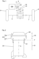
- an electrified vehicle axle which is equipped with an electric machine EM.
- the electric machine EM is connected via a two-stage reduction gear 1 to an axle differential 3, from which right and left output shafts 5, 7 are guided to front wheels 9 of the vehicle axle.
- the rotor shaft 11 of the electric machine EM is connected via an indicated torque-transmitting coupling 6 (for example, a spline) with a transmission input shaft 12.
- a fixed gear 13, which is part of a reduction gear 1, is located on the transmission input shaft 12.
- the fixed gear 13 of the transmission input shaft 12 meshes with a fixed gear 17 located on an intermediate shaft 15.
- Another fixed gear 19 of the intermediate shaft 15 meshes with an input-side external gear 21 of the front axle differential 3.
- the electric machine EM is aligned axially parallel to the two output shafts 5, 7.
- the electric machine EM has a cylindrical stator housing 23 which is extended in the axial direction by a gear housing 25. Both the reduction gear 1 and the axle differential 3 are arranged in the gear housing 25.
- the gear housing 25 is in the Figure 2 constructed in two parts, namely an intermediate housing 27 and a housing cover 29.
- the intermediate housing 27 and the stator housing 23 are screwed together via first screw points S1 at a joining plane F, at which (viewed in the axial direction) a stator housing side 31 merges into a gear housing side 33.
- the intermediate housing 27 and the housing cover 29 are screwed together at second screw points S2.
- One shaft end of the transmission input shaft 12 is mounted in the housing cover 29 via a rotary bearing 14.
- the intermediate shaft 15 is rotatably mounted in both the housing cover 29 and the intermediate housing 27 via further rotary bearings 16.
- the rotor shaft 11 is rotatably mounted in a bearing opening 8 of the intermediate housing 27 via a rotary bearing 10.
- a screw bolt 35 is guided through a thread-free screw hole 37 of the intermediate housing 27 and is in threaded engagement with an internally threaded bore 39 formed on the stator housing 23.
- An opening edge region 41 of the gear housing screw hole 37 is therefore clamped between a bolt head 43 of the screw bolt 35 and the stator housing 23.
- a screw bolt 45 is guided through a thread-free screw hole 47 of the housing cover 29 and is in threaded engagement with an internally threaded bore 49 formed on the intermediate housing 27.
- An opening edge region 51 of the housing cover screw hole 47 is clamped between the bolt head 53 of the screw bolt 45 and the intermediate housing 27.
- the internal threaded holes 39, 49 are designed as blind holes, each with a closed hole base.
- the screw axes of the two screw points S1, S2 are aligned parallel to the stator housing axis A.
- the joining directions of the two screw bolts 35, 45 are identical, i.e. from top to bottom in the processing position shown.
- stator housing 23, the intermediate housing 27 and the housing cover 29 are assembled in a processing station (not shown):
- a provision process step (not shown) the still empty stator housing 23 is provided and equipped with electrical machine components (for example a stator 55 and a rotor 57).
- the stator housing 23 is in a processing position in which the stator housing axis A in the vertical processing direction z ( Figures 4 and 5 ) is aligned.
- the joining surfaces 59 ( Figure 4 ) for connection to the intermediate housing 27 are therefore positioned on the top of the stator housing.
- a second feed step the housing cover 29 is moved from top to bottom onto an intermediate housing joining surface 61 ( Figure 4 or 5 ) is set.
- the screw bolt 45 is screwed in a vertical joining direction from top to bottom into the second screw point S2 between the intermediate housing 27 and the housing cover 29.
- a core of the invention is that the bolt head 43 of the screw bolt 35 is located on the gearbox housing side 33. This allows tool access to the bolt head 43 of the screw bolt 35 on the gearbox housing side 33 without any interference contours.
- the bolt head 43 of the screw bolt 35 is arranged inside the housing.
- an additional turning process step is carried out before the screwing process step is carried out, in which the stator housing 23 is turned over by 180°.
- the turned over stator housing 23 is arranged on the intermediate housing 27 and there in a Screwing process step.
- the reversing process step is necessary to avoid a hanging screw connection, i.e. a screw connection of the stator housing 23 in a joining direction from bottom to top.
Landscapes
- Engineering & Computer Science (AREA)
- Mechanical Engineering (AREA)
- General Engineering & Computer Science (AREA)
- Chemical & Material Sciences (AREA)
- Combustion & Propulsion (AREA)
- Transportation (AREA)
- General Details Of Gearings (AREA)
- Connection Of Motors, Electrical Generators, Mechanical Devices, And The Like (AREA)
Description
- Die Erfindung betrifft eine Antriebsvorrichtung für eine Fahrzeugachse eines zweispurigen Fahrzeugs nach dem Oberbegriff des Anspruches 1 sowie ein Verfahren zum Zusammenbau einer solchen Antriebsvorrichtung nach Anspruch 6.
- Eine elektrifizierte Fahrzeugachse für ein zweispuriges Kraftfahrzeug weist eine Elektromaschine auf, die über ein Getriebe sowie über ein Achsdifferenzial auf Abtriebswellen abtreibt, die jeweils zu einem Fahrzeugrad führen.
- In einer bekannten Antriebsvorrichtung ist ein zylindrisches Statorgehäuse der Elektromaschine in Axialrichtung mit einem Getriebegehäuse verlängert, die an einer Fügeebene miteinander verschraubt sind. An der Fügeebene geht eine Statorgehäuse-Seite in eine Getriebegehäuse-Seite über. Die Schraubachse an der Schraubstelle ist achsparallel zur Statorgehäuse-Achse ausgerichtet.
- In einem nicht von der Erfindung umfassten Vergleichsbeispiel ist die Schraubstelle wie folgt realisiert: Ein Schraubbolzen der Schraubstelle ist durch ein gewindefreies Schraubloch des Statorgehäuses geführt und in Gewindeeingriff mit einer am Getriebegehäuse ausgebildeten Innengewinde-Bohrung, so dass ein Öffnungsrandbereich des Statorgehäuse-Schraubloches zwischen einem Bolzenkopf des Schraubbolzens und dem Getriebegehäuse verspannt ist. Dadurch ergibt sich im Stand der Technik der folgende Zusammenbau-Prozess: So wird zunächst in einem Bereitstellungs-Prozessschritt ein noch leeres Statorgehäuse bereitgestellt und mit Elektromaschinen-Komponenten bestückt. Die Statorgehäuse-Achse ist dabei in Bearbeitungs-Hochrichtung derart ausgerichtet, dass die Fügefläche zur Anbindung an das Getriebegehäuse auf der Statorgehäuse-Oberseite positioniert ist. Anschließend erfolgt ein Umschlag-Prozessschritt, in dem das bestückte Statorgehäuse um 180° umgeschlagen wird. Anschließend wird das umgeschlagene Statorgehäuse in einem Zustell-Prozessschritt in vertikaler Zustellbewegung von oben nach unten auf das Getriebegehäuse gesetzt. Zum Prozessende wird ein Schraub-Prozessschritt durchgeführt, in dem der Schraubbolzen in einer vertikalen Fügerichtung von oben nach unten in die Schraubstelle zwischen Statorgehäuse und Getriebegehäuse eingeschraubt wird.
- Im obigen Vergleichsbeispiel befindet sich der Bolzenkopf des Schraubbolzens, das heißt der Werkzeugansatz, auf der Statorgehäuse-Seite (das heißt unmittelbar seitlich neben dem Außenumfang des Statorgehäuses). Ein Werkzeugzugang zum Bolzenkopf ist aufgrund der beengten Raumverhältnisse nur störkonturbehaftet möglich. Zudem ist im Zusammenbau-Prozess ein fertigungstechnisch sowie montagetechnisch aufwendiger Umschlag-Prozessschritt durchzuführen, damit eine hängende Verschraubung, das heißt eine Verschraubung in einer Fügerichtung von unten nach oben, vermieden werden kann.
- Eine gattungsgemäße Antriebsvorrichtung für eine Fahrzeugachse ist aus der
DE 10 2018 106 799 A1 bekannt. - Aus der
DE 10 2015 112 684 A1 ist ein Aktuator zum Ankoppeln an die Verstellwelle eines Verbrennungsmotors zum Einstellen des Expansionshubes bekannt. Aus derDE 10 2019 133 843 A1 ist eine elektrische Antriebseinheit für Fahrzeuge bekannt. Aus derDE 43 42 185 A1 ist ein Getriebe bekannt. Die Aufgabe der Erfindung besteht darin, eine Antriebsvorrichtung für eine Fahrzeugachse bereitzustellen, bei der ein Zusammenbau-Prozess im Vergleich zum Stand der Technik vereinfacht ist. - Die Aufgabe ist durch die Merkmale des Anspruches 1 oder des Anspruches 6 gelöst. Bevorzugte Weiterbildungen der Erfindung sind in den Unteransprüchen offenbart.
- Die Erfindung geht von einer Antriebsvorrichtung für eine Fahrzeugachse aus, bei der eine Elektromaschine über ein Getriebe auf Abtriebswellen abtreibt, die jeweils zu einem Fahrzeugrad führen. In der Antriebsvorrichtung ist ein zylindrisches Statorgehäuse der Elektromaschine in Axialrichtung mit einem Getriebegehäuse verlängert. Das Statorgehäuse und das Getriebegehäuse sind an einer Fügeebene miteinander verschraubt, an der eine Statorgehäuse-Seite in eine Getriebegehäuse-Seite übergeht. Dabei weist die zumindest eine Schraubstelle zwischen dem Getriebegehäuse und dem Statorgehäuse einen Schraubbolzen auf, der durch ein gewindefreies Schraubloch des Getriebegehäuses geführt ist und in Gewindeeingriff mit einer am Statorgehäuse ausgebildeten Innengewinde-Bohrung ist. Auf diese Weise kann ein Öffnungsrandbereich des Getriebegehäuses-Schraubloches zwischen einem Bolzenkopf des Schraubbolzens und dem Statorgehäuse verspannt sein.
- Dabei befindet sich der, einen Werkzeugansatz bildende Schraubbolzen-Bolzenkopf nicht mehr auf der störkonturbehafteten Statorgehäuse-Seite, sondern vielmehr auf der Getriebegehäuse-Seite. Der Werkzeugzugang zum Schraubbolzen erfolgt daher störkonturfrei auf der Getriebegehäuse-Seite.
- Erfindungsgemäß mündet das gewindefreie Schraubloch des Getriebegehäuses in den Getriebegehäuse-Innenraum. Auf diese Weise ist der Bolzenkopf des Schraubbolzens im Zusammenbauzustand im Getriebegehäuse-Innenraum positioniert und daher vor getriebeäußeren Einflüssen geschützt.
- In einer konkreten Ausführungsvariante kann das Getriebegehäuse aus zwei Gehäuseteilen aufgebaut sein, die in einer Axialrichtung hintereinander angeordnet sind. Die beiden Gehäuseteile können ein Zwischengehäuse und ein Gehäusedeckel sein. Das Zwischengehäuse wird unmittelbar mit dem Statorgehäuse verschraubt, während der Gehäusedeckel am Zwischengehäuse verschraubt wird und den Getriebegehäuse-Innenraum in Axialrichtung schließt.
- Das Zwischengehäuse und der Gehäusedeckel können an zumindest einer zweiten Schraubstelle miteinander verschraubt sein. Diese kann ebenfalls einen Schraubbolzen aufweisen, der durch ein gewindefreies Schraubloch des Gehäusedeckels geführt ist und in Gewindeeingriff mit einer am Zwischengehäuse ausgebildeten Innengewinde-Bohrung ist. Auf diese Weise wird ein Öffnungsrandbereich des Gehäusedeckel-Schraubloches zwischen einem Schraubbolzen-Bolzenkopf und dem Zwischengewinde verspannt.
- Im Hinblick auf eine automatisierte Serienfertigung ist es bevorzugt, wenn die Fügerichtung des Schraubbolzens an der ersten Schraubstelle und des Schraubbolzens an der zweiten Schraubstelle zueinander identisch sind. Die Innengewinde-Bohrung an der ersten Schraubstelle und/oder an der zweiten Schraubstelle kann bevorzugt als ein Sackloch mit geschlossenem Bohrgrund ausgebildet sein. Zudem können die Schraubachsen der ersten Schraubstelle und/oder der zweiten Schraubstelle achsparallel zur Statorgehäuse-Achse ausgerichtet sein.
- Mit der Erfindung ist der nachfolgend beschriebene Zusammenbau-Prozess durchführbar: So wird zunächst in einem Bereitstellungs-Prozessschritt ein noch leeres Statorgehäuse bereitgestellt und mit Elektromaschinenkomponenten bestückt. Die Statorgehäuse-Achse ist dabei in einer Bearbeitungs-Hochrichtung ausgerichtet, und zwar so, dass die Fügefläche zur Anbindung an das Getriebegehäuse (insbesondere an das Zwischengehäuse) auf der Statorgehäuse-Oberseite positioniert ist. Anschließend erfolgt ein Zustellschritt, in dem in einer vertikalen Zustellbewegung das Getriebegehäuse (insbesondere das Zwischengehäuse) von oben nach unten auf die Statorgehäuse-Fügefläche gesetzt wird. Zum Prozessende wird ein Schraub-Prozess durchgeführt, in dem der Schraubbolzen in einer vertikalen Fügerichtung von oben nach unten in die Schraubstelle zwischen Statorgehäuse und Getriebegehäuse (insbesondere Zwischengehäuse) eingeschraubt wird.
- Anschließend kann ein zweiter Zustellschritt erfolgen, in dem in einer vertikalen Zustellbewegung der Gehäusedeckel von oben nach unten auf eine korrespondierende Zwischengehäuse-Fügefläche gesetzt wird. In einem anschließenden Schraub-Prozessschritt wird ein Schraubbolzen in einer vertikalen Fügerichtung von oben nach unten in die Schraubstelle zwischen Gehäusedeckel und Zwischengehäuse eingeschraubt.
- Bevorzugt ist daher im Vergleich zum Stand der Technik kein Umschlag-Prozessschritt mehr erforderlich, um eine hängende Verschraubung, das heißt eine Verschraubung in Fügerichtung von unten nach oben zu vermeiden.
- Nachfolgend ist ein Ausführungsbeispiel der Erfindung anhand der beigefügten Figuren beschrieben.
- Es zeigen:
- Fig. 1
- in einer schematischen Darstellung eine elektrifizierte Fahrzeugachse;
- Fig. 2
- eine zusammengebaute Antriebsvorrichtung für die Fahrzeugachse;
- Fig. 3
- in einer Detailansicht die Gehäuse-Verschraubungen in der Antriebsvorrichtung;
- Fig. 4 und 5
- jeweils Ansichten, die einen Zusammenbau-Prozess veranschaulichen;
- Fig. 6
- in einer Ansicht entsprechend der
Fig. 3 ein Vergleichsbeispiel. - In der
Figur 1 ist eine elektrifizierte Fahrzeugachse gezeigt, die mit einer Elektromaschine EM ausgestattet ist. Die Elektromaschine EM ist über ein zweistufiges Vorgelege 1 mit einem Achsdifferenzial 3 trieblich verbunden, von dem rechte und linke Abtriebswellen 5, 7 zu Vorderrädern 9 der Fahrzeugachse geführt sind. Die Rotorwelle 11 der Elektromaschine EM ist über eine angedeutete momentenübertragende Kopplung 6 (zum Beispiel, eine Passverzahnung) mit einer Getriebeeingangswelle 12 koaxial verbunden. Auf der Getriebeeingangswelle 12 sitzt ein Festzahnrad 13, das Bestandteil eines Vorgeleges 1 ist. Das Festzahnrad 13 der Getriebeeingangswelle 12 kämmt mit einem auf einer Zwischenwelle 15 sitzenden Festzahnrad 17. Ein weiteres Festzahnrad 19 der Zwischenwelle 15 kämmt mit einem eingangsseitigen Außenzahnrad 21 des Vorderachsdifferenzials 3. Die Elektromaschine EM ist achsparallel zu den beiden Abtriebswellen 5, 7 ausgerichtet. - Wie aus der
Figur 2 hervorgeht, weist die Elektromaschine EM ein zylindrisches Statorgehäuse 23 auf, das in der Axialrichtung mit einem Getriebegehäuse 25 verlängert ist. Im Getriebegehäuse 25 sind sowohl das Vorgelege 1 als auch das Achsdifferenzial 3 angeordnet. Das Getriebegehäuse 25 ist in derFigur 2 zweiteilig aufgebaut, und zwar aus einem Zwischengehäuse 27 und einem Gehäusedeckel 29. Das Zwischengehäuse 27 und das Statorgehäuse 23 sind über erste Schraubstellen S1 an einer Fügeebene F miteinander verschraubt, an der (in Axialrichtung betrachtet) eine Statorgehäuse-Seite 31 in eine Getriebegehäuse-Seite 33 übergeht. In gleicher Weise sind das Zwischengehäuse 27 und der Gehäusedeckel 29 an zweiten Schraubstellen S2 miteinander verschraubt. - Gemäß der
Figur 3 ist ein Wellenende der Getriebeeingangswelle 12 über ein Drehlager 14 im Gehäusedeckel 29 gelagert. Die Zwischenwelle 15 ist über weitere Drehlager 16 sowohl im Gehäusedeckel 29 als auch im Zwischengehäuse 27 drehgelagert. Die Rotorwelle 11 ist über ein Drehlager 10 in einer Lageröffnung 8 des Zwischengehäuses 27 drehgelagert. - In der in der
Figur 3 gezeigten ersten Schraubstelle S1 ist ein Schraubbolzen 35 durch ein gewindefreies Schraubloch 37 des Zwischengehäuses 27 geführt und in Gewindeeingriff mit einer am Statorgehäuse 23 ausgebildeten Innengewinde-Bohrung 39. Ein Öffnungsrandbereich 41 des Getriebegehäuse-Schraubloches 37 ist daher zwischen einem Bolzenkopf 43 des Schraubbolzens 35 und dem Statorgehäuse 23 verspannt. - In der in der
Figur 3 gezeigten zweiten Schraubstelle S2 ist ein Schraubbolzen 45 durch ein gewindefreies Schraubloch 47 des Gehäusedeckels 29 geführt und in Gewindeeingriff mit einer am Zwischengehäuse 27 ausgebildeten Innengewinde-Bohrung 49. Ein Öffnungsrandbereich 51 des Gehäusedeckel-Schraubloches 47 ist zwischen dem Bolzenkopf 53 des Schraubbolzens 45 und dem Zwischengehäuse 27 verspannt. - Wie aus der
Figur 3 weiter hervorgeht, sind die Innengewinde-Bohrungen 39, 49 als Sacklöcher mit jeweils geschlossenem Bohrungsgrund ausgebildet. Die Schraubachsen der beiden Schraubstellen S1, S2 sind achsparallel zur Statorgehäuse-Achse A ausgerichtet. Zudem sind die Fügerichtungen der beiden Schraubbolzen 35, 45 identisch, das heißt in der dargestellten Bearbeitungsposition von oben nach unten. - Nachfolgend wird anhand der
Figuren 4 und 5 ein Zusammenbau-Prozess beschrieben, bei dem das Statorgehäuse 23, das Zwischengehäuse 27 und der Gehäusedeckel 29 in einer nicht gezeigten Bearbeitungsstation zusammengebaut werden: So wird in einem (nicht dargestellten) Bereitstellungs-Prozessschritt das noch leere Statorgehäuse 23 bereitgestellt und mit Elektromaschinen-Komponenten (zum Beispiel einem Stator 55 und einem Rotor 57) bestückt. Im Bereitstellungs-Prozessschritt befindet sich das Statorgehäuse 23 in einer Bearbeitungsposition, in der die Statorgehäuse-Achse A in der Bearbeitungs-Hochrichtung z (Figuren 4 und 5 ) ausgerichtet ist. Die Fügeflächen 59 (Figur 4 ) zur Anbindung an das Zwischengehäuse 27 sind daher auf der Statorgehäuse-Oberseite positioniert. - Anschließend erfolgt ein Zustell-Prozessschritt, in dem in einer vertikalen Zustellbewegung das Zwischengehäuse 27 von oben nach unten auf die Statorgehäuse-Fügeflächen 59 gesetzt wird. In einem abschließenden Schraub-Prozessschritt (
Figur 4 ) wird der Schraubbolzen 35 in einer vertikalen Fügerichtung von oben nach unten in die Schraubstelle S1 zwischen Statorgehäuse 23 und Zwischengehäuse 27 eingeschraubt. - In einem zweiten Zustellschritt wird in einer vertikalen Zustellbewegung der Gehäusedeckel 29 von oben nach unten auf eine Zwischengehäuse-Fügefläche 61 (
Figur 4 oder 5 ) gesetzt. Im folgenden Schraub-Prozessschritt (Figur 5 ) wird der Schraubbolzen 45 in einer vertikalen Fügerichtung von oben nach unten in die zweite Schraubstelle S2 zwischen Zwischengehäuse 27 und Gehäusedeckel 29 eingeschraubt. - Die Fügerichtungen der beiden Schraubbolzen 35, 37 an der ersten Schraubstelle S1 und an der zweiten Schraubstelle S1, S2 sind identisch. Ein Kern der Erfindung besteht darin, dass sich der Bolzenkopf 43 des Schraubbolzens 35 auf der Getriebegehäuse-Seite 33 befindet. Dadurch kann ein Werkzeugzugang zum Bolzenkopf 43 des Schraubbolzens 35 auf der Getriebegehäuse-Seite 33 störkonturfrei erfolgen. Zudem ist der Bolzenkopf 43 des Schraubbolzens 35 im Gehäuse-Inneren angeordnet.
- Ein solcher störkonturfreier Werkzeugzugang zum Schraubbolzen 35 der ersten Schraubstelle S1 ist dagegen in dem, in der
Figur 6 gezeigten Vergleichsbeispiel nicht möglich: In derFigur 6 ist der Schraubbolzen 35 (von unten nach oben) durch ein gewindefreies Schraubloch 63 des Statorgehäuses 23 geführt und in Gewindeeingriff mit einer am Zwischengehäuse 27 ausgebildeten Innengewinde-Bohrung 65. Ein Öffnungsrandbereich des gewindefreien Schraubloches 63 ist zwischen dem Bolzenkopf 43 des Schraubbolzens 35 und dem Zwischengehäuse 27 verspannt. Der Werkzeugansatz am Bolzenkopf 43 des Schraubbolzens 35 befindet sich in derFigur 6 nicht auf der Getriebegehäuse-Seite 33, sondern auf der Statorgehäuse-Seite 31, und zwar unmittelbar seitlich neben dem Außenumfang des Statorgehäuses 23. Aufgrund der beengten Bauraumverhältnisse ist lediglich ein störkonturbehafteter Werkzeugzugang zum Bolzenkopf 43 des Schraubbolzens 35 ermöglicht, bei dem der Statorgehäuse-Außenumfang eine, einen einfachen Werkzeugzugang entgegenstehende Störkontur bildet. Zudem erfolgt vor Durchführung des Schraub-Prozessschrittes ein zusätzlicher Umschlag-Prozessschritt, in dem das Statorgehäuse 23 um 180° umgeschlagen wird. In einem anschließenden Zustell-Prozessschritt wird das umgeschlagene Statorgehäuse 23 auf dem Zwischengehäuse 27 angeordnet und dort in einem Schraub-Prozessschritt verschraubt. Der Umschlag-Prozessschritt ist erforderlich, um eine hängende Verschraubung, das heißt eine Verschraubung des Statorgehäuses 23 in einer Fügerichtung von unten nach oben zu vermeiden. -
- 1
- Vorgelege
- 3
- Achsdifferenzial
- 6
- momentenübertragende Kopplung
- 5, 7
- Abtriebswellen
- 8
- Lageröffnung
- 9
- Fahrzeugräder
- 10
- Drehlager
- 11
- Rotorwelle
- 12
- Getriebeeingangswelle
- 13
- Festzahnrad
- 14
- Drehlager
- 15
- Zwischenwelle
- 16
- weitere Drehlager
- 17, 19
- Festzahnräder
- 21
- Außenzahnrad
- 23
- Statorgehäuse
- 25
- Getriebegehäuse
- 27
- Zwischengehäuse
- 29
- Gehäusedeckel
- 31
- Statorgehäuse-Seite
- 33
- Getriebegehäuse-Seite
- 35
- Schraubbolzen
- 37
- gewindefreies Schraubloch
- 39
- Innengewinde-Bohrung
- 41
- Öffnungsrandbereich
- 43
- Bolzenkopf
- 45
- Schraubbolzen
- 47
- gewindefreies Schraubloch
- 49
- Innengewinde-Bohrung
- 51
- Öffnungsrandbereich
- 53
- Bolzenkopf
- 55
- Stator
- 57
- Rotor
- 59
- Fügeflächen
- 61
- Fügeflächen
- F
- Fügeebene
- S1
- erste Schraubstelle
- S2
- zweite Schraubstelle
- A
- Statorgehäuse-Achse
- EM
- Elektromaschine
Claims (7)
- Antriebsvorrichtung für eine Fahrzeugachse eines Fahrzeugs, mit einer Elektromaschine (EM), die über ein Getriebe (1, 3) auf Abtriebswellen (5, 7) abtreibt, die jeweils zu einem Fahrzeugrad (9) führen, wobei ein zylindrisches Statorgehäuse (23) der Elektromaschine (EM) in Axialrichtung mit einem Getriebegehäuse (25) verlängert ist, wobei zumindest eine Schraubstelle (S1) zwischen dem Statorgehäuse (23) und dem Getriebegehäuse (25) einen Schraubbolzen (35) aufweist, der durch ein gewindefreies Schraubloch (37) des Getriebegehäuses (25) geführt ist und in Gewindeeingriff mit einer am Statorgehäuse (23) ausgebildeten Innengewinde-Bohrung (39) ist, dadurch gekennzeichnet, dass das gewindefreie Schraubloch (37) des Getriebegehäuses (25) in den Getriebegehäuse-Innenraum mündet, so dass im Zusammenbauzustand der Bolzenkopf (43) des Schraubbolzens (35) im Getriebegehäuse-Innenraum angeordnet ist.
- Antriebsvorrichtung nach Anspruch 1, dadurch gekennzeichnet, dass das Statorgehäuse (23) und das Getriebegehäuse (25) an einer Fügeebene (F) miteinander verschraubt sind, an der eine Statorgehäuse-Seite (31) in eine Getriebegehäuse-Seite (33) übergeht, und dass insbesondere der Bolzenkopf (43) des Schraubbolzens (35) einen Werkzeugansatz aufweist, der sich auf der Getriebegehäuse-Seite (33) befindet, so dass ein Werkzeugzugang zum Schraubbolzen (35) auf der Getriebegehäuse-Seite (33) liegt.
- Antriebsvorrichtung nach einem der vorhergehenden Ansprüche,
dadurch gekennzeichnet, dass das Getriebegehäuse (25) aus zwei Gehäuseteilen (27, 29) aufgebaut ist, die in einer Axialrichtung hintereinander angeordnet sind, und zwar insbesondere aus einem Zwischengehäuse (27) und einem Gehäusedeckel (29), der den Getriebegehäuse-Innenraum in Axialrichtung schließt. - Antriebsvorrichtung nach Anspruch 3, dadurch gekennzeichnet, dass das Zwischengehäuse (27) und der Gehäusedeckel (29) an zumindest einer zweiten Schraubstelle (S2) miteinander verschraubt sind, und dass die zweite Schraubstelle (S2) einen Schraubbolzen (45) aufweist, der durch ein gewindefreies Schraubloch (47) des Gehäusedeckels (29) geführt ist und in Gewindeeingriff mit einer am Zwischengehäuse (27) ausgebildeten Innengewinde-Bohrung (49) ist, so dass insbesondere ein Öffnungsrandbereich (51) des Gehäusedeckel-Schraubloches (47) zwischen einem Bolzenkopf (53) des Schraubbolzens (45) und dem Zwischengehäuse (27) verspannt ist.
- Antriebsvorrichtung nach einem der vorhergehenden Ansprüche,
dadurch gekennzeichnet, dass die Innengewinde-Bohrung (39, 49) als ein Sackloch mit geschlossenem Bohrungsgrund ausgebildet ist, und/oder dass die Schraubachse der ersten Schraubstelle (S1) und/oder die Schraubachse der zweiten Schraubstelle (S2) achsparallel zur Statorgehäuse-Achse (A) ausgerichtet sind, und/oder dass die Fügerichtung des Schraubbolzens (35) an der ersten Schraubstelle (S1) und des Schraubbolzens (45) an der zweiten Schraubstelle (S2) identisch sind. - Verfahren zum Zusammenbau einer Antriebsvorrichtung nach einem der vorhergehenden Ansprüche, mit- einem Bereitstellungs-Prozessschritt, in dem das noch leere Statorgehäuse (23) bereitgestellt wird und mit Elektromaschinen-Komponenten (55, 57) bestückt wird, wobei die Statorgehäuse-Achse (A) in einer Bearbeitungs-Hochrichtung (z) ausgerichtet ist, so dass die Statorgehäuse-Fügeflächen (59) zur Anbindung an das Getriebegehäuse (25), insbesondere Zwischengehäuse (27), auf der Statorgehäuse-Oberseite positioniert sind,- einem Zustell-Prozessschritt, in dem das Getriebegehäuse (25), insbesondere Zwischengehäuse (27), in einer vertikalen Zustellbewegung von oben nach unten auf die Statorgehäuse-Fügeflächen (59) gesetzt wird, und- einem Schraub-Prozessschritt, in dem der Schraubbolzen (35) in einer vertikalen Fügerichtung von oben nach unten in die Schraubstelle (S1) zwischen Statorgehäuse (23) und Getriebegehäuse (25), insbesondere Zwischengehäuse (27), eingeschraubt wird.
- Verfahren nach Anspruch 6, dadurch gekennzeichnet, dass im weiteren Prozessverlauf- ein zweiter Zustell-Prozessschritt, in dem der Gehäusedeckel (29) in einer vertikalen Zustellbewegung von oben nach unten auf Zwischengehäuse-Fügeflächen (61) gesetzt wird, und- ein zweiter Schraub-Prozessschritt folgt, in dem der Schraubbolzen (45) in einer vertikalen Fügerichtung von oben nach unten in die Schraubstelle (S2) zwischen Gehäusedeckel (29) und Zwischengehäuse (27) eingeschraubt wird.
Applications Claiming Priority (2)
| Application Number | Priority Date | Filing Date | Title |
|---|---|---|---|
| DE102021112973.7A DE102021112973A1 (de) | 2021-05-19 | 2021-05-19 | Antriebsvorrichtung für eine Fahrzeugachse |
| PCT/EP2022/062060 WO2022243041A1 (de) | 2021-05-19 | 2022-05-04 | Antriebsvorrichtung für eine fahrzeugachse |
Publications (2)
| Publication Number | Publication Date |
|---|---|
| EP4297986A1 EP4297986A1 (de) | 2024-01-03 |
| EP4297986B1 true EP4297986B1 (de) | 2024-10-16 |
Family
ID=81750668
Family Applications (1)
| Application Number | Title | Priority Date | Filing Date |
|---|---|---|---|
| EP22724796.2A Active EP4297986B1 (de) | 2021-05-19 | 2022-05-04 | Antriebsvorrichtung für eine fahrzeugachse |
Country Status (5)
| Country | Link |
|---|---|
| US (1) | US20240229912A1 (de) |
| EP (1) | EP4297986B1 (de) |
| CN (1) | CN117355432A (de) |
| DE (1) | DE102021112973A1 (de) |
| WO (1) | WO2022243041A1 (de) |
Family Cites Families (14)
| Publication number | Priority date | Publication date | Assignee | Title |
|---|---|---|---|---|
| DE4342185A1 (de) | 1993-12-10 | 1995-06-14 | Zeitlauf Gmbh Getriebe U Verza | Getriebe |
| JP4515200B2 (ja) * | 2004-09-02 | 2010-07-28 | 本田技研工業株式会社 | 4輪駆動車両用マニュアルトランスミッションの歯打ち音低減構造 |
| DE102008025497A1 (de) | 2008-05-28 | 2009-12-03 | Continental Automotive Gmbh | Motor-/Getriebeeinheit mit Elektromaschine |
| DE102012204774A1 (de) | 2012-03-26 | 2013-09-26 | Zf Friedrichshafen Ag | Anordnung einer elektrischen Maschine |
| DE102015101367A1 (de) * | 2015-01-30 | 2016-08-04 | Gkn Driveline International Gmbh | Elektroantriebsanordnung |
| DE102015112684A1 (de) | 2015-08-03 | 2017-02-09 | Ovalo Gmbh | Aktuator, insbesondere zum Ankoppeln an die Verstellwelle eines Verbrennungsmotors zum Einstellen des Expansionshubes und/oder des Verdichtungsverhältnisses |
| JP6518718B2 (ja) * | 2017-05-09 | 2019-05-22 | 本田技研工業株式会社 | 動力装置 |
| US11273700B2 (en) * | 2017-08-18 | 2022-03-15 | Arvinmeritor Technology, Llc | Axle assembly having an electric motor module |
| DE102018106799B4 (de) * | 2018-03-22 | 2022-02-17 | Dr. Ing. H.C. F. Porsche Aktiengesellschaft | Elektrischer Achsantrieb |
| DE102018215933A1 (de) * | 2018-09-19 | 2020-03-19 | ZF Drivetech (Suzhou) Co.Ltd. | Getriebevorrichtung mit einem Planetengetriebe und einem Differentialgetriebe sowie Antriebsvorrichtung zum elektrischen Antrieb eines Kraftfahrzeugs |
| US10787073B2 (en) | 2018-12-11 | 2020-09-29 | Ford Global Technologies, Llc | Electric drive unit for vehicle with clockable gearbox |
| CN209426548U (zh) * | 2018-12-28 | 2019-09-24 | 郑州江东汽车零部件有限公司 | 一种新型能源汽车后桥主减速器 |
| CN112803650A (zh) * | 2021-01-21 | 2021-05-14 | 珠海格力电器股份有限公司 | 壳体组件、电机组件和电机 |
| WO2022201537A1 (ja) * | 2021-03-26 | 2022-09-29 | 武蔵精密工業株式会社 | 伝動装置 |
-
2021
- 2021-05-19 DE DE102021112973.7A patent/DE102021112973A1/de active Pending
-
2022
- 2022-05-04 WO PCT/EP2022/062060 patent/WO2022243041A1/de not_active Ceased
- 2022-05-04 CN CN202280035279.XA patent/CN117355432A/zh active Pending
- 2022-05-04 US US18/561,604 patent/US20240229912A1/en active Pending
- 2022-05-04 EP EP22724796.2A patent/EP4297986B1/de active Active
Also Published As
| Publication number | Publication date |
|---|---|
| EP4297986A1 (de) | 2024-01-03 |
| DE102021112973A1 (de) | 2022-11-24 |
| WO2022243041A1 (de) | 2022-11-24 |
| CN117355432A (zh) | 2024-01-05 |
| US20240229912A1 (en) | 2024-07-11 |
Similar Documents
| Publication | Publication Date | Title |
|---|---|---|
| DE102005034930B4 (de) | Elektrisch verstellbares Getriebe | |
| DE69901141T2 (de) | Herstellungsverfahren für Kraftfahrzeug- Ausgleichsgetriebe | |
| WO2023186744A1 (de) | Antriebsvorrichtung für ein kraftfahrzeug, insbesondere für einen kraftwagen | |
| EP0180748A1 (de) | Planetengetriebe | |
| EP1456561A1 (de) | Planetengetriebe, getriebemotor und baureihe von getriebemotoren | |
| EP1769174B1 (de) | Differential für eine fahrzeugachse | |
| DE102013213708A1 (de) | Schneckengetriebe für eine Lenkhilfevorrichtung eines Kraftfahrzeuges mit Spielausgleich | |
| DE102012014343A1 (de) | Aufnahmeteilkonstruktion für ein Drehzahluntersetzungsgetriebe, Aufnahmeverfahren und Drehzahluntersetzungsgetriebe der exzentrisch oszillierenden Bauart. | |
| DE10336867B4 (de) | Fahrzeuglenkung mit elektrischem Hilfsantrieb | |
| DE102007000943B4 (de) | Verriegelungseinrichtung für eine Welle eines Lenksystems | |
| DE102004008538B4 (de) | Differential mit einer Bolzenbefestigungsbaugruppe | |
| DE102012223870B4 (de) | Kegelradanordnung | |
| DE102014117646A1 (de) | Planetengetriebe für ein lenksystem und verfahren zur montage eines planetengetriebes | |
| DE102021104649A1 (de) | Lenkungsaktuator für eine Hinterachslenkung und Verfahren zur Montage eines Lenkungsaktuators | |
| DE102020131137A1 (de) | Vorrichtung zur automatisierten Herstellung von Schraubverbindungen | |
| EP3527845A1 (de) | Lageranordnung in einem schraubrad-planetengetriebe | |
| WO2020182399A1 (de) | Differentialgetriebe | |
| EP4297986B1 (de) | Antriebsvorrichtung für eine fahrzeugachse | |
| DE102017219546B4 (de) | Zahnradanordnung | |
| EP1556185A1 (de) | Verfahren zur herstellung eines spurstangengehäuses | |
| DE102007020828A1 (de) | Ritzel | |
| EP1910707A1 (de) | Stellantrieb für armaturen mit einem planetengetriebe | |
| WO2023052045A1 (de) | Antriebsvorrichtung für einen öffnungsmechanismus zum öffnen eines beweglichen öffnungselementes eines fahrzeuges, sowie öffnungssystem für ein fahrzeug | |
| DE102021213292A1 (de) | Getriebegehäuse mit einem lastaufnehmenden Gehäusegrundkörper und einer unbelasteten Gehäuseabdeckung sowie Getriebe und Antriebsanordnung mit dem Getriebegehäuse | |
| DE102021200067A1 (de) | Aktuator für einen aktiv verstellbaren Wankstabilisator |
Legal Events
| Date | Code | Title | Description |
|---|---|---|---|
| STAA | Information on the status of an ep patent application or granted ep patent |
Free format text: STATUS: UNKNOWN |
|
| STAA | Information on the status of an ep patent application or granted ep patent |
Free format text: STATUS: THE INTERNATIONAL PUBLICATION HAS BEEN MADE |
|
| PUAI | Public reference made under article 153(3) epc to a published international application that has entered the european phase |
Free format text: ORIGINAL CODE: 0009012 |
|
| STAA | Information on the status of an ep patent application or granted ep patent |
Free format text: STATUS: REQUEST FOR EXAMINATION WAS MADE |
|
| 17P | Request for examination filed |
Effective date: 20230928 |
|
| AK | Designated contracting states |
Kind code of ref document: A1 Designated state(s): AL AT BE BG CH CY CZ DE DK EE ES FI FR GB GR HR HU IE IS IT LI LT LU LV MC MK MT NL NO PL PT RO RS SE SI SK SM TR |
|
| GRAP | Despatch of communication of intention to grant a patent |
Free format text: ORIGINAL CODE: EPIDOSNIGR1 |
|
| STAA | Information on the status of an ep patent application or granted ep patent |
Free format text: STATUS: GRANT OF PATENT IS INTENDED |
|
| DAV | Request for validation of the european patent (deleted) | ||
| DAX | Request for extension of the european patent (deleted) | ||
| INTG | Intention to grant announced |
Effective date: 20240513 |
|
| P01 | Opt-out of the competence of the unified patent court (upc) registered |
Free format text: CASE NUMBER: APP_39786/2024 Effective date: 20240703 |
|
| GRAS | Grant fee paid |
Free format text: ORIGINAL CODE: EPIDOSNIGR3 |
|
| GRAA | (expected) grant |
Free format text: ORIGINAL CODE: 0009210 |
|
| STAA | Information on the status of an ep patent application or granted ep patent |
Free format text: STATUS: THE PATENT HAS BEEN GRANTED |
|
| AK | Designated contracting states |
Kind code of ref document: B1 Designated state(s): AL AT BE BG CH CY CZ DE DK EE ES FI FR GB GR HR HU IE IS IT LI LT LU LV MC MK MT NL NO PL PT RO RS SE SI SK SM TR |
|
| REG | Reference to a national code |
Ref country code: GB Ref legal event code: FG4D Free format text: NOT ENGLISH |
|
| REG | Reference to a national code |
Ref country code: DE Ref legal event code: R096 Ref document number: 502022001928 Country of ref document: DE Ref country code: CH Ref legal event code: EP |
|
| REG | Reference to a national code |
Ref country code: IE Ref legal event code: FG4D Free format text: LANGUAGE OF EP DOCUMENT: GERMAN |
|
| REG | Reference to a national code |
Ref country code: LT Ref legal event code: MG9D |
|
| REG | Reference to a national code |
Ref country code: NL Ref legal event code: MP Effective date: 20241016 |
|
| PG25 | Lapsed in a contracting state [announced via postgrant information from national office to epo] |
Ref country code: NL Free format text: LAPSE BECAUSE OF FAILURE TO SUBMIT A TRANSLATION OF THE DESCRIPTION OR TO PAY THE FEE WITHIN THE PRESCRIBED TIME-LIMIT Effective date: 20241016 |
|
| PG25 | Lapsed in a contracting state [announced via postgrant information from national office to epo] |
Ref country code: NL Free format text: LAPSE BECAUSE OF FAILURE TO SUBMIT A TRANSLATION OF THE DESCRIPTION OR TO PAY THE FEE WITHIN THE PRESCRIBED TIME-LIMIT Effective date: 20241016 |
|
| PG25 | Lapsed in a contracting state [announced via postgrant information from national office to epo] |
Ref country code: IS Free format text: LAPSE BECAUSE OF FAILURE TO SUBMIT A TRANSLATION OF THE DESCRIPTION OR TO PAY THE FEE WITHIN THE PRESCRIBED TIME-LIMIT Effective date: 20250216 Ref country code: PT Free format text: LAPSE BECAUSE OF FAILURE TO SUBMIT A TRANSLATION OF THE DESCRIPTION OR TO PAY THE FEE WITHIN THE PRESCRIBED TIME-LIMIT Effective date: 20250217 Ref country code: HR Free format text: LAPSE BECAUSE OF FAILURE TO SUBMIT A TRANSLATION OF THE DESCRIPTION OR TO PAY THE FEE WITHIN THE PRESCRIBED TIME-LIMIT Effective date: 20241016 |
|
| PG25 | Lapsed in a contracting state [announced via postgrant information from national office to epo] |
Ref country code: FI Free format text: LAPSE BECAUSE OF FAILURE TO SUBMIT A TRANSLATION OF THE DESCRIPTION OR TO PAY THE FEE WITHIN THE PRESCRIBED TIME-LIMIT Effective date: 20241016 |
|
| PG25 | Lapsed in a contracting state [announced via postgrant information from national office to epo] |
Ref country code: BG Free format text: LAPSE BECAUSE OF FAILURE TO SUBMIT A TRANSLATION OF THE DESCRIPTION OR TO PAY THE FEE WITHIN THE PRESCRIBED TIME-LIMIT Effective date: 20241016 |
|
| PG25 | Lapsed in a contracting state [announced via postgrant information from national office to epo] |
Ref country code: ES Free format text: LAPSE BECAUSE OF FAILURE TO SUBMIT A TRANSLATION OF THE DESCRIPTION OR TO PAY THE FEE WITHIN THE PRESCRIBED TIME-LIMIT Effective date: 20241016 |
|
| PG25 | Lapsed in a contracting state [announced via postgrant information from national office to epo] |
Ref country code: NO Free format text: LAPSE BECAUSE OF FAILURE TO SUBMIT A TRANSLATION OF THE DESCRIPTION OR TO PAY THE FEE WITHIN THE PRESCRIBED TIME-LIMIT Effective date: 20250116 |
|
| PG25 | Lapsed in a contracting state [announced via postgrant information from national office to epo] |
Ref country code: LV Free format text: LAPSE BECAUSE OF FAILURE TO SUBMIT A TRANSLATION OF THE DESCRIPTION OR TO PAY THE FEE WITHIN THE PRESCRIBED TIME-LIMIT Effective date: 20241016 Ref country code: GR Free format text: LAPSE BECAUSE OF FAILURE TO SUBMIT A TRANSLATION OF THE DESCRIPTION OR TO PAY THE FEE WITHIN THE PRESCRIBED TIME-LIMIT Effective date: 20250117 |
|
| PG25 | Lapsed in a contracting state [announced via postgrant information from national office to epo] |
Ref country code: PL Free format text: LAPSE BECAUSE OF FAILURE TO SUBMIT A TRANSLATION OF THE DESCRIPTION OR TO PAY THE FEE WITHIN THE PRESCRIBED TIME-LIMIT Effective date: 20241016 |
|
| PG25 | Lapsed in a contracting state [announced via postgrant information from national office to epo] |
Ref country code: RS Free format text: LAPSE BECAUSE OF FAILURE TO SUBMIT A TRANSLATION OF THE DESCRIPTION OR TO PAY THE FEE WITHIN THE PRESCRIBED TIME-LIMIT Effective date: 20250116 |
|
| PG25 | Lapsed in a contracting state [announced via postgrant information from national office to epo] |
Ref country code: SM Free format text: LAPSE BECAUSE OF FAILURE TO SUBMIT A TRANSLATION OF THE DESCRIPTION OR TO PAY THE FEE WITHIN THE PRESCRIBED TIME-LIMIT Effective date: 20241016 |
|
| PGFP | Annual fee paid to national office [announced via postgrant information from national office to epo] |
Ref country code: DE Payment date: 20250531 Year of fee payment: 4 |
|
| PG25 | Lapsed in a contracting state [announced via postgrant information from national office to epo] |
Ref country code: DK Free format text: LAPSE BECAUSE OF FAILURE TO SUBMIT A TRANSLATION OF THE DESCRIPTION OR TO PAY THE FEE WITHIN THE PRESCRIBED TIME-LIMIT Effective date: 20241016 |
|
| REG | Reference to a national code |
Ref country code: DE Ref legal event code: R097 Ref document number: 502022001928 Country of ref document: DE |
|
| PG25 | Lapsed in a contracting state [announced via postgrant information from national office to epo] |
Ref country code: EE Free format text: LAPSE BECAUSE OF FAILURE TO SUBMIT A TRANSLATION OF THE DESCRIPTION OR TO PAY THE FEE WITHIN THE PRESCRIBED TIME-LIMIT Effective date: 20241016 |
|
| PGFP | Annual fee paid to national office [announced via postgrant information from national office to epo] |
Ref country code: FR Payment date: 20250520 Year of fee payment: 4 |
|
| PG25 | Lapsed in a contracting state [announced via postgrant information from national office to epo] |
Ref country code: RO Free format text: LAPSE BECAUSE OF FAILURE TO SUBMIT A TRANSLATION OF THE DESCRIPTION OR TO PAY THE FEE WITHIN THE PRESCRIBED TIME-LIMIT Effective date: 20241016 |
|
| PGFP | Annual fee paid to national office [announced via postgrant information from national office to epo] |
Ref country code: AT Payment date: 20250721 Year of fee payment: 4 |
|
| PG25 | Lapsed in a contracting state [announced via postgrant information from national office to epo] |
Ref country code: SK Free format text: LAPSE BECAUSE OF FAILURE TO SUBMIT A TRANSLATION OF THE DESCRIPTION OR TO PAY THE FEE WITHIN THE PRESCRIBED TIME-LIMIT Effective date: 20241016 |
|
| PG25 | Lapsed in a contracting state [announced via postgrant information from national office to epo] |
Ref country code: CZ Free format text: LAPSE BECAUSE OF FAILURE TO SUBMIT A TRANSLATION OF THE DESCRIPTION OR TO PAY THE FEE WITHIN THE PRESCRIBED TIME-LIMIT Effective date: 20241016 |
|
| PG25 | Lapsed in a contracting state [announced via postgrant information from national office to epo] |
Ref country code: IT Free format text: LAPSE BECAUSE OF FAILURE TO SUBMIT A TRANSLATION OF THE DESCRIPTION OR TO PAY THE FEE WITHIN THE PRESCRIBED TIME-LIMIT Effective date: 20241016 |
|
| PLBE | No opposition filed within time limit |
Free format text: ORIGINAL CODE: 0009261 |
|
| STAA | Information on the status of an ep patent application or granted ep patent |
Free format text: STATUS: NO OPPOSITION FILED WITHIN TIME LIMIT |
|
| PG25 | Lapsed in a contracting state [announced via postgrant information from national office to epo] |
Ref country code: SE Free format text: LAPSE BECAUSE OF FAILURE TO SUBMIT A TRANSLATION OF THE DESCRIPTION OR TO PAY THE FEE WITHIN THE PRESCRIBED TIME-LIMIT Effective date: 20241016 |
|
| 26N | No opposition filed |
Effective date: 20250717 |
|
| REG | Reference to a national code |
Ref country code: CH Ref legal event code: H13 Free format text: ST27 STATUS EVENT CODE: U-0-0-H10-H13 (AS PROVIDED BY THE NATIONAL OFFICE) Effective date: 20251223 |
|
| PG25 | Lapsed in a contracting state [announced via postgrant information from national office to epo] |
Ref country code: LU Free format text: LAPSE BECAUSE OF NON-PAYMENT OF DUE FEES Effective date: 20250504 |
|
| PG25 | Lapsed in a contracting state [announced via postgrant information from national office to epo] |
Ref country code: CH Free format text: LAPSE BECAUSE OF NON-PAYMENT OF DUE FEES Effective date: 20250531 |
|
| REG | Reference to a national code |
Ref country code: BE Ref legal event code: MM Effective date: 20250531 |
|
| PG25 | Lapsed in a contracting state [announced via postgrant information from national office to epo] |
Ref country code: MC Free format text: LAPSE BECAUSE OF FAILURE TO SUBMIT A TRANSLATION OF THE DESCRIPTION OR TO PAY THE FEE WITHIN THE PRESCRIBED TIME-LIMIT Effective date: 20241016 |
|
| PG25 | Lapsed in a contracting state [announced via postgrant information from national office to epo] |
Ref country code: IE Free format text: LAPSE BECAUSE OF NON-PAYMENT OF DUE FEES Effective date: 20250504 |
|
| PG25 | Lapsed in a contracting state [announced via postgrant information from national office to epo] |
Ref country code: BE Free format text: LAPSE BECAUSE OF NON-PAYMENT OF DUE FEES Effective date: 20250531 |