EP4298024B1 - Sleeve-shaped outer part, combination packaging container equipped therewith, and method for separating the combination packaging container - Google Patents
Sleeve-shaped outer part, combination packaging container equipped therewith, and method for separating the combination packaging container Download PDFInfo
- Publication number
- EP4298024B1 EP4298024B1 EP22707701.3A EP22707701A EP4298024B1 EP 4298024 B1 EP4298024 B1 EP 4298024B1 EP 22707701 A EP22707701 A EP 22707701A EP 4298024 B1 EP4298024 B1 EP 4298024B1
- Authority
- EP
- European Patent Office
- Prior art keywords
- outer part
- container
- face
- packaging container
- combination packaging
- Prior art date
- Legal status (The legal status is an assumption and is not a legal conclusion. Google has not performed a legal analysis and makes no representation as to the accuracy of the status listed.)
- Active
Links
Images

Classifications
-
- B—PERFORMING OPERATIONS; TRANSPORTING
- B65—CONVEYING; PACKING; STORING; HANDLING THIN OR FILAMENTARY MATERIAL
- B65D—CONTAINERS FOR STORAGE OR TRANSPORT OF ARTICLES OR MATERIALS, e.g. BAGS, BARRELS, BOTTLES, BOXES, CANS, CARTONS, CRATES, DRUMS, JARS, TANKS, HOPPERS, FORWARDING CONTAINERS; ACCESSORIES, CLOSURES, OR FITTINGS THEREFOR; PACKAGING ELEMENTS; PACKAGES
- B65D1/00—Rigid or semi-rigid containers having bodies formed in one piece, e.g. by casting metallic material, by moulding plastics, by blowing vitreous material, by throwing ceramic material, by moulding pulped fibrous material or by deep-drawing operations performed on sheet material
- B65D1/22—Boxes or like containers with side walls of substantial depth for enclosing contents
- B65D1/26—Thin-walled containers, e.g. formed by deep-drawing operations
-
- B—PERFORMING OPERATIONS; TRANSPORTING
- B65—CONVEYING; PACKING; STORING; HANDLING THIN OR FILAMENTARY MATERIAL
- B65D—CONTAINERS FOR STORAGE OR TRANSPORT OF ARTICLES OR MATERIALS, e.g. BAGS, BARRELS, BOTTLES, BOXES, CANS, CARTONS, CRATES, DRUMS, JARS, TANKS, HOPPERS, FORWARDING CONTAINERS; ACCESSORIES, CLOSURES, OR FITTINGS THEREFOR; PACKAGING ELEMENTS; PACKAGES
- B65D1/00—Rigid or semi-rigid containers having bodies formed in one piece, e.g. by casting metallic material, by moulding plastics, by blowing vitreous material, by throwing ceramic material, by moulding pulped fibrous material or by deep-drawing operations performed on sheet material
- B65D1/22—Boxes or like containers with side walls of substantial depth for enclosing contents
- B65D1/26—Thin-walled containers, e.g. formed by deep-drawing operations
- B65D1/265—Drinking cups
-
- B—PERFORMING OPERATIONS; TRANSPORTING
- B65—CONVEYING; PACKING; STORING; HANDLING THIN OR FILAMENTARY MATERIAL
- B65D—CONTAINERS FOR STORAGE OR TRANSPORT OF ARTICLES OR MATERIALS, e.g. BAGS, BARRELS, BOTTLES, BOXES, CANS, CARTONS, CRATES, DRUMS, JARS, TANKS, HOPPERS, FORWARDING CONTAINERS; ACCESSORIES, CLOSURES, OR FITTINGS THEREFOR; PACKAGING ELEMENTS; PACKAGES
- B65D25/00—Details of other kinds or types of rigid or semi-rigid containers
- B65D25/34—Coverings or external coatings
- B65D25/36—Coverings or external coatings formed by applying sheet material
-
- B—PERFORMING OPERATIONS; TRANSPORTING
- B65—CONVEYING; PACKING; STORING; HANDLING THIN OR FILAMENTARY MATERIAL
- B65D—CONTAINERS FOR STORAGE OR TRANSPORT OF ARTICLES OR MATERIALS, e.g. BAGS, BARRELS, BOTTLES, BOXES, CANS, CARTONS, CRATES, DRUMS, JARS, TANKS, HOPPERS, FORWARDING CONTAINERS; ACCESSORIES, CLOSURES, OR FITTINGS THEREFOR; PACKAGING ELEMENTS; PACKAGES
- B65D3/00—Rigid or semi-rigid containers having bodies or peripheral walls of curved or partially-curved cross-section made by winding or bending paper without folding along defined lines
- B65D3/22—Rigid or semi-rigid containers having bodies or peripheral walls of curved or partially-curved cross-section made by winding or bending paper without folding along defined lines with double walls; with walls incorporating air-chambers; with walls made of laminated material
-
- B—PERFORMING OPERATIONS; TRANSPORTING
- B65—CONVEYING; PACKING; STORING; HANDLING THIN OR FILAMENTARY MATERIAL
- B65D—CONTAINERS FOR STORAGE OR TRANSPORT OF ARTICLES OR MATERIALS, e.g. BAGS, BARRELS, BOTTLES, BOXES, CANS, CARTONS, CRATES, DRUMS, JARS, TANKS, HOPPERS, FORWARDING CONTAINERS; ACCESSORIES, CLOSURES, OR FITTINGS THEREFOR; PACKAGING ELEMENTS; PACKAGES
- B65D81/00—Containers, packaging elements, or packages, for contents presenting particular transport or storage problems, or adapted to be used for non-packaging purposes after removal of contents
- B65D81/38—Containers, packaging elements, or packages, for contents presenting particular transport or storage problems, or adapted to be used for non-packaging purposes after removal of contents with thermal insulation
- B65D81/3865—Containers, packaging elements, or packages, for contents presenting particular transport or storage problems, or adapted to be used for non-packaging purposes after removal of contents with thermal insulation drinking cups or like containers
- B65D81/3869—Containers, packaging elements, or packages, for contents presenting particular transport or storage problems, or adapted to be used for non-packaging purposes after removal of contents with thermal insulation drinking cups or like containers formed with double walls, i.e. hollow
-
- B—PERFORMING OPERATIONS; TRANSPORTING
- B65—CONVEYING; PACKING; STORING; HANDLING THIN OR FILAMENTARY MATERIAL
- B65D—CONTAINERS FOR STORAGE OR TRANSPORT OF ARTICLES OR MATERIALS, e.g. BAGS, BARRELS, BOTTLES, BOXES, CANS, CARTONS, CRATES, DRUMS, JARS, TANKS, HOPPERS, FORWARDING CONTAINERS; ACCESSORIES, CLOSURES, OR FITTINGS THEREFOR; PACKAGING ELEMENTS; PACKAGES
- B65D81/00—Containers, packaging elements, or packages, for contents presenting particular transport or storage problems, or adapted to be used for non-packaging purposes after removal of contents
- B65D81/38—Containers, packaging elements, or packages, for contents presenting particular transport or storage problems, or adapted to be used for non-packaging purposes after removal of contents with thermal insulation
- B65D81/3865—Containers, packaging elements, or packages, for contents presenting particular transport or storage problems, or adapted to be used for non-packaging purposes after removal of contents with thermal insulation drinking cups or like containers
- B65D81/3874—Containers, packaging elements, or packages, for contents presenting particular transport or storage problems, or adapted to be used for non-packaging purposes after removal of contents with thermal insulation drinking cups or like containers formed of different materials, e.g. laminated or foam filling between walls
-
- B—PERFORMING OPERATIONS; TRANSPORTING
- B65—CONVEYING; PACKING; STORING; HANDLING THIN OR FILAMENTARY MATERIAL
- B65D—CONTAINERS FOR STORAGE OR TRANSPORT OF ARTICLES OR MATERIALS, e.g. BAGS, BARRELS, BOTTLES, BOXES, CANS, CARTONS, CRATES, DRUMS, JARS, TANKS, HOPPERS, FORWARDING CONTAINERS; ACCESSORIES, CLOSURES, OR FITTINGS THEREFOR; PACKAGING ELEMENTS; PACKAGES
- B65D81/00—Containers, packaging elements, or packages, for contents presenting particular transport or storage problems, or adapted to be used for non-packaging purposes after removal of contents
- B65D81/38—Containers, packaging elements, or packages, for contents presenting particular transport or storage problems, or adapted to be used for non-packaging purposes after removal of contents with thermal insulation
- B65D81/3876—Containers, packaging elements, or packages, for contents presenting particular transport or storage problems, or adapted to be used for non-packaging purposes after removal of contents with thermal insulation insulating sleeves or jackets for cans, bottles, barrels, etc.
-
- B—PERFORMING OPERATIONS; TRANSPORTING
- B65—CONVEYING; PACKING; STORING; HANDLING THIN OR FILAMENTARY MATERIAL
- B65D—CONTAINERS FOR STORAGE OR TRANSPORT OF ARTICLES OR MATERIALS, e.g. BAGS, BARRELS, BOTTLES, BOXES, CANS, CARTONS, CRATES, DRUMS, JARS, TANKS, HOPPERS, FORWARDING CONTAINERS; ACCESSORIES, CLOSURES, OR FITTINGS THEREFOR; PACKAGING ELEMENTS; PACKAGES
- B65D2565/00—Wrappers or flexible covers; Packaging materials of special type or form
- B65D2565/38—Packaging materials of special type or form
- B65D2565/381—Details of packaging materials of special type or form
- B65D2565/385—Details of packaging materials of special type or form especially suited for or with means facilitating recycling
Definitions
- the invention relates to a sleeve-shaped outer part formed from a blank for encasing a cup-shaped inner container, as well as to a combination packaging container formed from an inner container and the outer part.
- the invention also relates to a method for separating the combination packaging container into its inner container and the outer part by separating the overlapping area of the outer part.
- a predetermined separation region comprises an actuating means with a detection section for separating separation sections located on both sides.
- the detection section is arranged offset laterally from the separating sections, which are aligned convergingly and are spaced apart from an imaginary straight connecting line between them, as seen in the circumferential direction.
- a separate predetermined separation section is formed in the jacket of the outer part between each detection section end and a respective end of the separating sections. The lower end of the outer part facing the closed end of the inner container is supported on a support shoulder projecting radially outwards.
- the WO 2009/130043 A1 describes, among other things, a sleeve-shaped outer part for forming a combination packaging container.
- the outer part is formed from a blank by erecting and mutually connecting ends in an overlapping area.
- an actuating means for separating a predetermined separation area is provided, which is arranged between the two end areas spaced apart in the axial direction.
- the actuating means is formed by an opening extending up to the overlapping area, wherein the longitudinal side of the overlapping The end forms the detection section.
- an actuating tab is provided that can be removed from the casing along a U-shaped circumferential line, with the weakening line surrounding the actuating tab ending on the long side of the overlapping end.
- a packaging container has become known with a first container part having a container base and a container wall extending from the container base in the direction of a container edge, and with a second container part reinforcing the container wall in the form of a sleeve detachably connected to the first container part and at least partially lying against the outer surface of the container wall.
- the second container part has a weakening line running from an upper edge of the second container part facing the container rim towards a lower edge of the second container part facing the container bottom.
- the second container part can be detached from the first container part by cutting through the second container part along the weakening line.
- the second container part further has a gripping area that can be manually grasped to cut through the second container part, from which the second container part can be detached from the first container part.
- the weakening line has an engagement section that delimits the gripping area and has a reinforced weakening and/or a cutting line, which forms the starting section for cutting through the second container part along the weakening line. Furthermore, an access area is provided that adjoins the gripping area and lies on the side of the weakening line opposite the gripping area.
- the access area has two predetermined cutting lines that run transversely to the weakening line and end on one side in the engagement section of the weakening line. This ensures that, after separation along the predetermined separation lines and the engaging section, the access area remains firmly connected to the edge area of the second container part that does not have the gripping area.
- a perfect separation of the predetermined separation area adjacent to the gripping area could not be achieved in all applications.
- the object of the present invention was to overcome the disadvantages of the prior art and to provide a sleeve-shaped outer part and a combination packaging container comprising a cup-shaped inner container with a sleeve-shaped outer part surrounding the cup-shaped inner container.
- the sleeve-shaped outer part is securely positioned and held in the axial direction on the inner container without additional adhesive until the desired detachment from the inner container for recycling purposes.
- a method for separating the overlapping area and the subsequent separation of its outer part and inner container is also to be created.
- the advantage achieved in this way is that the support area or support section on the shoulder of the inner container, already defined by the first end face, is further improved by the provision or formation of the additional support device.
- the additional support device reduces the clear inner dimension compared to the undeformed configuration, thus achieving an even better locking effect on the inner container.
- tolerance-related manufacturing inaccuracies do not lead to any further disadvantages in the fixed positioning of the outer part on the inner container, and this is even possible without the adhesive point between the container shell and the outer part, which is otherwise usually applied for securing purposes. This creates an outer part that can also be more easily detached from the inner container for disposal.
- the additional support device comprises at least one support element, and the at least one support element defines the clear inner dimension.
- the at least one support element forms the additional support device and protrudes from the undeformed bottom-side edge region or edge section of the outer part in the direction of the longitudinal axis and forms the reduction of the clear inner dimension.
- the at least one support element is formed into the material of the blank, starting from an outer surface of the outer part toward an inner surface, and protrudes radially beyond the undeformed inner surface toward the longitudinal axis. This allows the material to be used directly to form the at least one support element, thus eliminating the need for additional components or parts. This also eliminates the need for additional material that would otherwise require separate treatment during separation and disposal.
- the at least one support element has a longitudinal extension starting from the first end face in the direction of the second end face. This allows a defined projection of the at least one support element can be realized via the inner surface of the cut or outer part, which forms the enlargement or widening of the base-side support area.
- Another possible embodiment has the features that multiple support elements are provided, and the support elements are arranged spaced apart from one another in the circumferential direction along the first end face. This allows for an even better support effect across the circumference, even under changing environmental conditions and/or during handling.
- the additional support device comprises at least one forming section, which is formed into the material of the blank from an inner surface of the outer part toward an outer surface, and which is arranged at a distance from the first end face. This subsequently allows the edge section to be aligned in the opposite direction.
- the at least one forming section viewed in axial section, has a preferably curved longitudinal profile, and an end section adjoining the forming section in the direction of the first end face is oriented so as to extend at an angle toward the longitudinal axis. This allows for additional stiffening of the bottom-side end section or the peripheral edge region.
- a further preferred embodiment is characterized in that the at least one forming section has a parallel longitudinal extension with respect to the first end face. This allows for a uniform design of the additional support device projecting toward the inner container.
- the forming section is arranged so as to extend continuously along the first end face in the circumferential direction. This allows a secure and uniform supporting effect to be achieved over the entire circumference, particularly in the case of inner containers with a round cross-sectional shape.
- Another alternative embodiment is characterized in that multiple forming sections are provided, and the forming sections are arranged spaced apart from one another in the circumferential direction along the first end face.
- This variant can be used in particular for inner containers that have rectilinear container walls when viewed in cross-section and each have a rounded corner region in the transition areas located therebetween. This prevents unwanted wrinkling in the transition areas.
- a further embodiment provides for an adhesive to be provided in the overlapping area between the two end sections, which adhesive has a first adhesive force value when viewed in the circumferential direction and a second adhesive force value in the radial direction, wherein the first adhesive force value is greater than the second adhesive force value. Due to the mutually different adhesive force values of the adhesive holding the blank together at its mutually facing end sections, on the one hand the cohesion can be made greater when viewed in the circumferential direction and, on the other hand, if the force is applied differently, an easier separation effect with a correspondingly reduced adhesive force can be made possible. This facilitates the separation process of the overlapping area when separating the outer part from the inner container. If a compressive force is exerted in the direction of the inner container, this can easily lead to a mutual detachment of the two interconnected end sections. This also allows a simple separation process of the outer part from the inner container during disposal.
- Another embodiment is characterized by the fact that at least one predetermined separation area is formed or provided in the outer shell of the outer part.
- at least one predetermined separation area is formed or provided in the outer shell of the outer part.
- the invention also relates to a combination packaging container comprising a cup-shaped inner container with a container shell, a base, a flange, a rear section located in the base area of the container shell and a shoulder as well as a A sleeve-shaped outer part designed according to the invention surrounds the inner container at least in part on its container shell.
- a further design provides for the sleeve-shaped outer part to be axially supported on the shoulder of the inner container by means of its additional support device, eliminating the need for an additional adhesive. This makes it even easier and, above all, more secure to separate the combination packaging container into the inner container and outer part after use. Even after the outer part has been separated, the outer part forms a single, integral piece, which can be easily and, above all, disposed of properly and recycled in one piece. Furthermore, by eliminating the additional adhesive, savings can be achieved and potential contamination of the machine during the adhesive application process can be avoided.
- the object of the invention is also achieved by a method for separating an outer part from an inner container, which together form the combination packaging container, in that a compressive force -F- directed towards the combination packaging container is applied during the separation process and the outer part and the container shell of the combination packaging container are spatially deformed and the applied compressive force -F- is at least partially converted into a separation force which at least partially separates the overlapping area by the spatial deformation.
- the applied compressive force -F- leads to a spatial deformation of the outer part and also of the container shell, whereby the compressive force -F- is at least partially deflected and converted into a separation force.
- the overlapping area of the outer part, held together by the adhesive or bonding agent is subjected to the separation force acting in the radial direction, depending on the orientation of the compressive force -F-.
- the separation force acting on the overlapping area causes the separation process, at least of the overlapping area.
- the person who is supposed to carry out the separation process can omit the search for and finding the actuating device for the desired separation area and the subsequent tearing process.
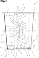
- a combination packaging container 1 is shown as an example of a multitude of possible different shapes, wherein the combination packaging containers 1 are cup- or bowl-shaped.
- the combination packaging container 1 comprises a cup- or bowl-shaped inner container 2 with a base 3 and a container shell 4.
- the inner container 2 further has an open end 5 on its side facing away from the base 3, wherein a flange 6 projecting outwardly beyond the container shell 4 can be provided in the region of its open end 5.
- the base 3 forms a closed end 7 for the container shell 4.
- the inner container 2 is preferably formed by a component produced in a deep-drawing process, which can be manufactured quickly and, above all, in a short cycle time.
- the deep-drawing process is well known and will therefore not be discussed in detail.
- the deep-drawing process is particularly suitable for producing the inner container 2 with a sufficient wall thickness to ensure tightness during storage, use, and disposal. This manufacturing process allows relatively thin walls of the inner container 2 to be produced.
- the inner container 2 can also be formed using other manufacturing processes, such as injection molding.
- a longitudinal axis 8 extends axially between the open end 5 and the end 7 closed by the base 3.
- This longitudinal axis 8 can also represent a central axis if the design is symmetrical.
- a sealing plate (not shown in detail) can be arranged in the area of the flange 6 or connected to it. In this case, the flange 6 forms a sealing flange.
- the inner container 2 In the axial direction and thus in the direction of the longitudinal axis 8, the inner container 2 has a container height 9 between its open end 5, in particular the flange 6, and the base 3, whereby the receiving volume of the inner container 2 is determined depending on the cross-sectional dimensions.
- the container height 9 in conjunction with the cross-sectional dimensions thus defines a receiving space of the inner container 2.
- the container shell 4 is understood to be that portion of the inner container 2 which extends predominantly axially between the open end 5, in particular the flange 6, and the base 3.
- the inner container 2 and its container shell 4 are preferably designed such that they taper conically from the open end toward the base.
- the container shell 4 of the inner container 2 can have a rear ledge 10 in its peripheral section adjacent to the base 3.
- the rear ledge 10 is also part of the container shell 4, but, viewed in axial section, is offset inwards with respect to an imaginary, straight connecting line between the flange 6 and the base 3.
- the rear ledge 10, in turn, has at least two rear ledge wall sections (not designated in more detail), wherein the two rear ledge wall sections, viewed in axial section, have a different inclination or direction with respect to the longitudinal axis 8 than the rest of the container shell 4.
- the rear ledge 10 is offset inwards and thus in the direction of the receiving space compared to the straight arrangement of the container shell 4 between the flange 6 and the base 3, viewed in axial section.
- the first rear-drawn wall section which directly adjoins the base 3, is arranged or configured to extend predominantly in the direction of the container height 9 toward the open end 5.
- the further rear-drawn wall section extends in a predominantly perpendicular direction with respect to the container height 9, starting from the end of the first rear-drawn wall section facing away from the base 3 toward the container shell 4.
- the further rear-drawn wall section forms a stacking shoulder. This stacking shoulder serves to support a similar combination packaging container 1 with its base 3, in particular the edge-side transition section between the base 3 and the container shell 4.
- the inner container 2 can have a shoulder 11 or a bead projecting towards the side facing away from the longitudinal axis 8 in the immediate transition area between the bottom 3 and the container shell 4, in particular between the bottom 3 and the rear section.
- the combination packaging container 1 further comprises an outer part 12 which is sleeve-shaped or jacket-shaped and surrounds the inner container 2 in the region of its container jacket 4 at least in sections or regions.
- the previously described shoulder 11 can, for example, serve to hold the sleeve-shaped outer part 12 on the inner container 2.
- the sleeve-shaped outer part 12 rests with its first end face 19 facing the bottom 3 of the inner container 2 on this shoulder 11 formed in the transition region.
- the shoulder 11 can thus also be referred to as a locking means for holding the outer part 12 on the inner container 2.
- the end face 19 forms a front edge in its longitudinal extent, which, in the joined position, defines a support area at least in sections and is supported against the shoulder.
- an unintentional detachment of the outer part 12 from the inner container 2 may occur.
- a further locking means in the region of the open end 5 can be, for example, the flange 6.
- the sleeve-shaped outer part 12 comprises a second end face 20, which in turn faces the open end 5 or the flange 6.
- the sleeve-shaped outer part 12 is preferably formed from a cellulose material, such as cardboard, with sufficient strength with regard to the absorption and transmission of, in particular, axially acting compressive forces, and is wound from a flat blank 13 into a sleeve, as is already well known.
- the blank 13 is usually printed in its undeformed, flat position and, if necessary, provided with an additional coating.
- a cellulose material is usually used as the material, although this can also be cardboard or strong paper produced using a recycling process. If a layer or ply of the outer part 12 is formed from a recycled material, an additional layer of a higher-quality paper can be arranged on or bonded to at least one of the surfaces. This additional layer ensures flawless printing for the production of decorations, labels, and product information.
- the sleeve-like or jacket-like outer part 12 leads to an additional reinforcement or stiffening effect of the inner container 2 and thus of the entire combination packaging container 1.
- the cardboard is additionally coated or sealed with a water-repellent material in the area of the cut edges. This is particularly advantageous when the combination packaging container 1 is exposed to increased moisture ingress. Coating the cardboard used for the outer part 12 with a water-repellent layer prevents the cardboard from swelling in a humid environment and ultimately detaching from the container shell 4 of the combination packaging container 1.
- the sleeve-shaped outer part 12 is wound from the mostly flat blank 13 into a sheath.
- end sections 14, 15 facing each other are then connected to one another in a simplified representation of the overlapping area 16.
- This is achieved by a so-called overlap seam, by means of which the first end section 14 and the second end section 15 adhere to one another, for example by means of an adhesive.
- the winding and subsequent connection of the two end sections 14, 15 can be carried out, as is already sufficiently known from the prior art, for example by gluing.
- the first end section 14 of the blank 13 ends with a first Longitudinal edge 17 and the second end section 15 in turn ends with a second longitudinal edge 18.
- the two longitudinal edges 17, 18 run approximately parallel to one another, wherein, viewed in the circumferential direction, the overlapping area 16 is formed therebetween with an overlap width.
- the outer part 12 further comprises the first end face 19 and the second end face 20, wherein the two end faces 19, 20 are spaced apart from one another and, in the erected state, define an overall height 21 of the shell.
- the previously described longitudinal axis 8 can also define the common longitudinal axis for the outer part 12, particularly when the outer part 12 is in its mounted position on the inner container 2.
- the overall height 21 of the shell is usually slightly less than the container height 9 of the inner container 2 in the same spatial direction—namely, in the direction of the longitudinal axis 8.
- predetermined separation area 22 is arranged and formed in the material of the outer part 12.
- the following detailed description of the predetermined separation area 22 corresponds to the design already described in the WO 2020/245148 A1 described. However, the predetermined separation area 22 could also be designed differently and deviating from this.
- At least one predetermined separation region 22 is provided in the casing of the outer part 12.
- the predetermined separation region 22 here comprises a first separation section 23, a second separation section 24, and an actuating means 25 for starting and initiating the severing process of the predetermined separation region 22 along the two separation sections 23, 24.
- the actuating means 25 is arranged between the two end faces 19, 20, viewed in the direction of the overall height 21 of the casing. It is advantageous if the actuating means 25 is arranged approximately centrally between the two end faces 19, 20, which are spaced apart from one another in the direction of the overall height 21, whereby this essentially corresponds to half the overall height 21.
- central refers to half the dimension of the actuating means 25 in the direction of the overall height 21 or the longitudinal axis 8.
- the two separating sections 23, 24 are provided on both sides of the actuating means 25 and each extend in the direction of the respective end face 19, 20.
- the two separating sections 23, 24 of the predetermined separating area 22 are each aligned so as to converge from the two end faces 19, 20 and thus define an imaginary, straight connecting line 26 between them, which is shown in dashed lines.
- the converging alignment of the two separating sections 23, 24 is in each case related to the direction of the actuating means 25.
- the two separating sections 23, 24 can either be aligned so as to be flush with one another, viewed in the direction of the overall height 21 of the casing, or they can run at a slight inclination with respect to the first longitudinal edge 17 in the direction of the actuating means 25 located between them. This slight inclination can further improve the separating process after the two separating sections 23, 24 have been separated towards the two end faces 19, 20.
- the imaginary connecting line 26 is assumed to run at the center of the predetermined separation points.
- the actuating means 25 defines a detection section 27 with a first detection section end 28 and a second detection section end 29 spaced apart from one another in the direction of the overall height 21.
- the two detection section ends 28, 29 are arranged or end at a distance 30 from one another in the direction of the overall height 21 of the casing.
- the detection section 27 of the actuating means 25 is arranged or formed outside the overlap region 16.
- the offset 31 can have a value selected from a range of values with a lower limit of 1.0 mm and an upper limit of 10.0 mm.
- the range of values can have a lower limit of 2.0 mm and an upper limit of 6.0 mm.
- the first separating section 23 in turn has a first end 32 facing the actuating means 25, wherein the second separating section 24 has a second end 33 facing the actuating means 25.
- the casing is formed without interruption due to the intended lateral offset 31 of the actuating means 25.
- the arrangement of the two in the direction The position of the ends 32, 33 of the separating sections 23, 24, which are spaced apart from one another by the overall height 21, with respect to the detection section 27 forming the actuating means 25 is selected such that the first detection section end 28 of the detection section 27 overlaps the adjacent first end 32 of the first separating section 23 on the side facing away from the second separating section 24.
- a first predetermined separating section 34 is formed in the casing of the outer part 12 between the first detection section end 28 and the first end 32 of the first separating section 23, as seen in the circumferential direction.
- the second detection section end 29 of the detection section 27 overlaps the adjacent second end 33 of the second separating section 24 on the side facing away from the first separating section 23.
- a second intended separating section 35 is also formed in the casing of the outer part 12 between the second detection section end 29 and the second end 33 of the second separating section 24, viewed in the circumferential direction.
- the two intended separating sections 34, 35 are formed by the reduced dimension of the casing material between the respective detection section end 28 or 29 and the respective end 32 or 33.
- the two ends 32 and 33 of the separating sections 23, 24 are arranged closer to one another than the two detection section ends 28 and 29, which are spaced apart by the distance 30.
- the two predetermined separation sections 34, 35 each form starting sections for the separation of the two separation sections 23, 24.
- Each of the two separating sections 23, 24 comprises a plurality of predetermined separation points arranged one behind the other in a row, which are usually formed as perforations, in particular also as short cuts, in the material of the outer part 12.
- first predetermined separation points 36 those predetermined separation points that are located directly adjacent to the respective detection section ends 28, 29 are referred to as first predetermined separation points 36.
- second predetermined separation points 37 and third predetermined separation points 38 are further predetermined separation points provided subsequently towards one of the two end faces 19, 20.
- the predetermined separation points 36, 37, 38 are aligned with respect to a plane 39 centrally and in normal alignment to the longitudinal axis 8 - see Fig. 1 - are designed and arranged in a mirror image of each other. Therefore, only those predetermined separation points 36, 37, 38 located in the area of the first separation section 23 will be described in more detail and are to be transferred analogously to the second separation section 24.
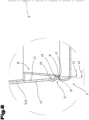
- an additional support device 40 is provided or formed by solely deforming the material of the blank 13.
- the additional support device 40 serves or is designed to ensure that the outer part 12 is or will be supported even more securely in the axial direction on the shoulder 11 of the inner container 2 until it is detached.
- the additional support device 40 is further designed such that a clear internal dimension of the finished formed outer part 12 is smaller than the undeformed design.
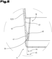
- the bottom end face 19 of the outer part 12 already forms or defines the support area interacting with the shoulder 11, which support area is further improved, in particular enlarged, and made more secure by the provision or formation of the additional support device 40.
- the additional support device 40 comprises at least one support element 41, but preferably a plurality of support elements 41 arranged at a distance from one another along the first end face 19, which support elements 41 are distributed over the circumference of the sleeve-shaped outer part 12.
- the individual support elements 41 are formed into the material of the blank 13 by forming or embossing and are thus each an integral part of the blank 13.
- the support elements 41 are formed and thus formed starting from an outer surface 42 of the outer part 12 in the direction of an inner surface 43. They thus protrude in the radial direction beyond the undeformed inner surface 43 in the direction of the longitudinal axis 8.
- the projection can have a value that originates from a value range whose lower limit is 0.05 mm, in particular 0.1 mm, and whose upper limit is 0.5 mm, in particular 0.2 mm.
- a clear inner dimension 44 of the additional support device 40 formed by the support elements 41 is thus smaller than an inner dimension 45 of the outer part 12 in its undeformed configuration without the support elements 41.
- the support element 41 has or the support elements 41 have a longitudinal extension starting from the first end face 19 in the direction of the second end face 20.
- the support element 41 or the support elements 41 extend as far as the first end face 19.
- the length of the at least one support element 41 can be, for example, a few millimeters and depends on the size and design of the rear part 10. Possible examples include 2 mm to 15 mm, preferably 5 mm to 10 mm.
- the cross-sectional shape of the support element 41 or the support elements 41 is shown only as an example. Instead of the rather angular cross-sectional shape shown here, a rounded or arcuate cross-sectional shape would also be conceivable.
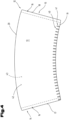
- Fig. 4 is the cut 13 to form the previously in the Fig. 1 to 3 described outer part 12 in its undeformed, flat position, whereby the same reference numerals or component designations are used for the same parts as in the previous Fig. 1 to 3 To avoid unnecessary repetition, please refer to the detailed description in the previous Fig. 1 to 3 pointed out or referred to.
- the previously described predetermined separation area 22 is not shown in detail here, but can also be provided as previously described as a possible and optional variant. Furthermore, the orientation of the individual support elements 41, starting from the first end face 19 facing the ground and moving toward the second end face 20, is more clearly visible here. Due to the arcuately curved longitudinal profile of the two end faces 19, 20 and their common center (center of the radius), the individual support elements 41 also have a longitudinal profile aligned toward the center.
- FIG. 5 and 6 a further and possibly independent embodiment of the outer part 12 formed from the blank 13 to the jacket is shown, wherein again the same reference numerals or component designations are used for the same parts as in the previous Fig. 1 to 4 To avoid unnecessary repetition, to the detailed description in the previous Fig. 1 to 4 pointed out or referred to.
- the blank 13 and the outer part 12 formed therefrom in turn comprise the additional support device 40, which, however, has a different design than the previously described embodiment.
- the additional support device 40 comprises at least one forming section 46, which is also molded into the material of the blank 13.
- the at least one forming section 46 is formed starting from the inner surface 43 of the outer part 12 in the direction of its outer surface 42.
- the at least one forming section 46 is arranged at a distance from the first end face 19 in the direction of the opposite second end face 20.
- the at least one forming section 46 can have a longitudinal profile that is mostly curved outward. Adjacent to the at least one forming section 46, an end section 47 is provided in the direction of the first end face 19. Thus, a corresponding end section 47 is also formed or arranged adjacent to each forming section 46. The end section 47 can, in turn, be oriented so as to extend at an angle toward the longitudinal axis 8.
- the at least one forming section 46 can have a parallel longitudinal extension with respect to the first end face 19. It is also possible for the forming section 46 to be arranged or formed to run continuously along the first end face 19 in the circumferential direction. Irrespective of this, it would also be conceivable for a plurality of forming sections 46 to be provided and for the forming sections 46 to be arranged spaced apart from one another along the first end face 19 in the circumferential direction.
- the at least one support element 41 defines in the upright position of the blank 13 to the outer part 12, in turn, the clear inner dimension 44, which is smaller than an inner dimension 45 of the outer part 12 in its undeformed configuration without the forming section 46.
- the bottom end of the outer part 12 is shown in the undeformed position in dashed lines in the Fig. 6 still hinted at.
- the forming section 46 Due to the formation and shaping of the forming section 46, it may be necessary to make the undeformed height between the first and second end faces 19, 20 somewhat longer in order to subsequently achieve support on the shoulder 11 on the one hand and to be able to cover the container shell 4 up to the flange 6 immediately adjacent thereto on the other hand.
- an adhesive or bonding agent is preferably used in the overlapping area 16 to be formed.
- This adhesive can be applied to one of the end sections 14 or 15 or to both of them, as is well known.
- the inner container 2 is usually made of a plastic or a degradable material that can be formed in a thermoforming process.
- the outer part 12 is preferably made of a cellulose material.
- the blank 13 can also be provided with a printed image on at least one of its flat sides, namely the outer surface 42 and/or the inner surface 43.
- the adhesive used in the overlapping area 16 has different adhesive force values depending on the direction of force acting on it, in particular the separation direction.
- the adhesive should have a sufficiently high adhesive force value to ensure sufficient mutual hold of the two end sections 14, 15 to one another under normal loads.
- the adhesive has a second adhesive force value which is different from the first adhesive force value.
- the first adhesive force value should be greater than the second adhesive force value.
- the compressive force -F- can be applied to the combination packaging container 1 in a wide variety of directions and is at least partially converted into a separation force which at least partially separates the overlapping region 16. In this case, the second adhesive force value is exceeded and the two end sections 14, 15, initially held together by the adhesive or adhesive, separate from each other, at least in sections.
- compression can be performed in the radial and/or axial directions. This spatially deforms the entire combination packaging container 1.
- a compressive force -F- is applied in the axial direction, the outer part 12 and also the container shell 4 bend in the direction of the longitudinal axis 8. Due to the lower adhesive force value in this force direction, the separation of the overlapping area 16 can be carried out or carried out.
- the sleeve-shaped outer part 12 can be supported even better and more securely in the axial direction on the shoulder 11 of the inner container 2 by means of its additional support device 40, without the need for an additional adhesive.
- the adhesive point previously provided for safety reasons between the inner surface 43 of the outer part 12 and the container shell 4 can thus be omitted and no longer needs to be provided.
- an unwanted adhesive connection between the outer part 12 and the inner container 2 can be avoided.
- the separation process of the target separation area 22 is then carried out during collection and/or during waste disposal, carried out mechanically by means of a press or a squeezing device.
- the combination packaging container on a support surface, either with its closed end or with the open end of the inner container, and then apply the compressive force -F- to the end facing away from the support surface in the direction of the support surface.
- the compressive force can be easily applied to the combination packaging container and introduced into it, e.g., using human force. The risk of injury can be minimized with an arrangement in which the compressive force is applied to the floor.
- the compressive force -F- on the combination packaging container in a parallel orientation with respect to a longitudinal axis extending between the open end and the closed end, or in an orientation angular to the longitudinal axis.
- the compressive force can be easily redirected, at least for the most part, into a tearing force acting in a predominantly radial direction, which leads to the outer part bursting open in its overlapping area. If the force application direction deviates from this, the spatial deformation can also cause the overlapping area to separate.
- the separation process of the combination packaging container 1 into its various components can be carried out either by a single person or during the collection and disposal process.
Landscapes
- Engineering & Computer Science (AREA)
- Mechanical Engineering (AREA)
- Ceramic Engineering (AREA)
- Packages (AREA)
- Cartons (AREA)
- Making Paper Articles (AREA)
- Wrappers (AREA)
Description
Die Erfindung betrifft ein aus einem Zuschnitt gebildetes manschettenförmiges Außenteil zum Ummanteln eines becherförmigen Innenbehälters sowie einen aus einem Innenbehälter und dem Außenteil gebildeten Kombi-Verpackungsbehälter. Die Erfindung betrifft aber auch weiters noch ein Verfahren zum Trennen des Kombi-Verpackungsbehälters in seinen Innenbehälter und das Außenteil durch Auftrennung des Überlappungsbereichs des Außenteils.The invention relates to a sleeve-shaped outer part formed from a blank for encasing a cup-shaped inner container, as well as to a combination packaging container formed from an inner container and the outer part. However, the invention also relates to a method for separating the combination packaging container into its inner container and the outer part by separating the overlapping area of the outer part.
Die
Die
Aus der
Der zweite Behälterteil weist eine von einem dem Behälterrand zugewandten oberen Rand des zweiten Behälterteils in Richtung auf einen dem Behälterboden zugewandten unteren Rand des zweiten Behälterteils verlaufende Schwächungslinie auf. Der zweite Behälterteil ist von dem ersten Behälterteil durch Durchtrennung des zweiten Behälterteils entlang der Schwächungslinie lösbar. Der zweite Behälterteil weist weiters einen zur Durchtrennung des zweiten Behälterteils manuell zu ergreifenden Anfassbereich auf, von dem ausgehend der zweite Behälterteil von dem ersten Behälterteil lösbar ist. Die Schwächungslinie weist einen den Anfassbereich begrenzenden Eingreifabschnitt mit einer verstärkten Schwächung und/oder einer Schnittlinie auf, der den Startabschnitt für die Durchtrennung des zweiten Behälterteils entlang der Schwächungslinie bildet. Weiters ist ein an den Anfassbereich angrenzender, auf der dem Anfassbereich gegenüberliegenden Seite der Schwächungslinie liegender Zugriffsbereich vorgesehen, der zwei quer zu der Schwächungslinie verlaufende Solltrennlinien aufweist, die einseitig in dem Eingreifabschnitt der Schwächungslinie enden. Damit wird erreicht, dass der Zugriffsbereich nach Trennung entlang der Solltrennlinien und des Eingreifabschnitts fest mit demjenigen Randbereich des zweiten Behälterteils verbunden bleibt, der den Anfassbereich nicht aufweist. Auch hier konnte nicht in allen Anwendungsfällen eine einwandfreie Durchtrennung des an den Anfassbereich anschließenden Solltrennbereichs erzielt werden.The second container part has a weakening line running from an upper edge of the second container part facing the container rim towards a lower edge of the second container part facing the container bottom. The second container part can be detached from the first container part by cutting through the second container part along the weakening line. The second container part further has a gripping area that can be manually grasped to cut through the second container part, from which the second container part can be detached from the first container part. The weakening line has an engagement section that delimits the gripping area and has a reinforced weakening and/or a cutting line, which forms the starting section for cutting through the second container part along the weakening line. Furthermore, an access area is provided that adjoins the gripping area and lies on the side of the weakening line opposite the gripping area. The access area has two predetermined cutting lines that run transversely to the weakening line and end on one side in the engagement section of the weakening line. This ensures that, after separation along the predetermined separation lines and the engaging section, the access area remains firmly connected to the edge area of the second container part that does not have the gripping area. Here, too, a perfect separation of the predetermined separation area adjacent to the gripping area could not be achieved in all applications.
Weitere Verpackungsbehälter sind aus der
Aufgabe der vorliegenden Erfindung war es, die Nachteile des Standes der Technik zu überwinden und ein manschettenförmiges Außenteil sowie einen Kombi-Verpackungsbehälter umfassend einen becherförmigen Innenbehälter mit einem diesen umgebenden manschettenförmigen Außenteil zur Verfügung zu stellen, bei dem das manschettenförmigen Außenteil in Axialrichtung an dem Innenbehälter ohne zusätzlicher Haftmittel sicher bis zur gewollten Ablösung vom Innenbehälter für Recyclingzwecke positioniert angeordnet und gehalten ist. Weiters soll aber auch noch ein Verfahren zur Auftrennung des Überlappungsbereichs und der nachfolgenden Trennung von dessen Außenteil und Innenbehälter geschaffen werden.The object of the present invention was to overcome the disadvantages of the prior art and to provide a sleeve-shaped outer part and a combination packaging container comprising a cup-shaped inner container with a sleeve-shaped outer part surrounding the cup-shaped inner container. In this case, the sleeve-shaped outer part is securely positioned and held in the axial direction on the inner container without additional adhesive until the desired detachment from the inner container for recycling purposes. Furthermore, a method for separating the overlapping area and the subsequent separation of its outer part and inner container is also to be created.
Diese Aufgabe wird durch ein manschettenförmig ausgebildetes Außenteil und einen das Außenteil und einen Innenbehälter umfassenden Kombi-Verpackungsbehälter gemäß den Ansprüchen gelöst.This object is achieved by a sleeve-shaped outer part and a combination packaging container comprising the outer part and an inner container according to the claims.
Das erfindungsgemäße manschettenförmige Außenteil dient zum Ummanteln eines becherförmigen Innenbehälters zur Bildung eines Kombi-Verpackungsbehälters,
- wobei der Innenbehälter einen Behältermantel aufweist, der von einem offenen Ende hin zu einem mit einem Boden verschlossenen Ende insbesondere konisch verjüngend ausgebildet ist,
- wobei das Außenteil aus einem Zuschnitt gebildet ist, welcher Zuschnitt in seinem aufgerichteten Zustand zu einem Mantel gewickelt ist und dabei ein erster Endabschnitt und ein diesem zugewendeter zweiter Endabschnitt des Mantels in einem Überlappungsbereich miteinander verbunden sind,
- wobei das Außenteil weiters eine erste Stirnseite und eine zweite Stirnseite aufweist und die beiden Stirnseiten voneinander beabstandet sind sowie im aufgerichteten Zustand eine Bauhöhe des Mantels mit einer sich in Richtung der Bauhöhe erstreckenden Längsachse definieren, wobei die erste Stirnseite zumindest abschnittsweise einen Abstützbereich definiert und weiters die erste Stirnseite dem Boden und die zweite Stirnseite dem offenen Ende des Innenbehälters zuwendbar ist, und
- wobei weiters noch eine zusätzliche Stützvorrichtung vorgesehen ist, welche zusätzliche Stützvorrichtung im Bereich der ersten Stirnseite des aus dem Zuschnitt gebildeten Außenteils angeordnet oder ausgebildet ist, und
- die zusätzliche Stützvorrichtung eine lichte innere Abmessung definiert welche kleiner ist als eine Innenabmessung des Außenteils in seiner unverformten Ausbildung im Bereich der ersten Stirnseite.
- wherein the inner container has a container shell which is designed to taper in particular conically from an open end to an end closed with a bottom,
- wherein the outer part is formed from a blank, which blank is wound in its erected state into a sheath, and a first end section and a second end section of the sheath facing the first end section are connected to one another in an overlapping region,
- wherein the outer part further comprises a first end face and a second end face, and the two end faces are spaced apart from one another and, in the erected state, define a construction height of the shell with a longitudinal axis extending in the direction of the construction height, wherein the first end face defines a support region at least in sections, and furthermore, the first end face can be turned towards the bottom and the second end face towards the open end of the inner container, and
- wherein an additional support device is further provided, which additional support device is arranged in the region of the first end face of the blank formed from the blank outer part is arranged or formed, and
- the additional support device defines a clear inner dimension which is smaller than an inner dimension of the outer part in its undeformed form in the region of the first end face.
Der dadurch erzielte Vorteil liegt darin, dass so der bereits von der ersten Stirnseite definierte Abstützbereich oder Abstützabschnitt an der Schulter des Innenbehälters durch das Vorsehen oder Ausbilden der zusätzlichen Stützvorrichtung noch weiter verbessert wird. In der unverformten Ausbildung des bodenseitigen Endbereichs des Zuschnitts bzw. des daraus gebildeten Außenteils wird durch die zusätzliche Abstützvorrichtung die lichte innere Abmessung bezüglich der unverformten Ausbildung verringert und so eine noch bessere Rastwirkung am Innenbehälter erzielt. So führen toleranzbedingte Fertigungsungenauigkeiten zu keinen weiteren Nachteilen bei der ortsfesten Positionierung des Außenteils am Innenbehälter und dies auch noch ohne dem ansonsten üblicherweise zu Sicherungszwecken angebrachten Klebepunkt zwischen dem Behältermantel und dem Außenteil. Damit wird ein Außenteil geschaffen, welcher auch leichter vom Innenbehälter für die Entsorgung abgelöst werden kann.The advantage achieved in this way is that the support area or support section on the shoulder of the inner container, already defined by the first end face, is further improved by the provision or formation of the additional support device. In the undeformed configuration of the bottom-side end region of the blank or of the outer part formed therefrom, the additional support device reduces the clear inner dimension compared to the undeformed configuration, thus achieving an even better locking effect on the inner container. In this way, tolerance-related manufacturing inaccuracies do not lead to any further disadvantages in the fixed positioning of the outer part on the inner container, and this is even possible without the adhesive point between the container shell and the outer part, which is otherwise usually applied for securing purposes. This creates an outer part that can also be more easily detached from the inner container for disposal.
Eine vorteilhafte Ausbildung sieht vor, dass die zusätzliche Stützvorrichtung zumindest ein Stützelement umfasst und das zumindest eine Stützelement die lichte innere Abmessung definiert. Das zumindest eine Stützelement bildet die zusätzliche Stützvorrichtung aus und ragt ausgehend vom unverformten bodenseitigen Randbereich oder Randabschnitt des Außenteils in Richtung auf die Längsachse vor und bildet die Verkleinerung der lichten Innenabmessung aus.An advantageous embodiment provides that the additional support device comprises at least one support element, and the at least one support element defines the clear inner dimension. The at least one support element forms the additional support device and protrudes from the undeformed bottom-side edge region or edge section of the outer part in the direction of the longitudinal axis and forms the reduction of the clear inner dimension.
Weiters kann es vorteilhaft sein, wenn das zumindest eine Stützelement in den Werkstoff des Zuschnitts ausgehend von einer Außenfläche des Außenteils in Richtung auf eine Innenfläche eingeformt ist und in radialer Richtung über die unverformte Innenfläche in Richtung auf die Längsachse vorragt. Damit kann der Werkstoff direkt zur Bildung des zumindest einen Stützelements verwendet werden und kann so auf zusätzliche Bauteile oder Bauteilkomponenten verzichtet werden. Damit wird auch kein zusätzlicher Werkstoff eingesetzt, der bei der Trennung und Entsorgung ansonsten gesondert zu behandeln wäre.Furthermore, it may be advantageous if the at least one support element is formed into the material of the blank, starting from an outer surface of the outer part toward an inner surface, and protrudes radially beyond the undeformed inner surface toward the longitudinal axis. This allows the material to be used directly to form the at least one support element, thus eliminating the need for additional components or parts. This also eliminates the need for additional material that would otherwise require separate treatment during separation and disposal.
Eine andere Ausführungsform zeichnet sich dadurch aus, dass das zumindest eine Stützelement eine Längserstreckung ausgehend von der ersten Stirnseite in Richtung auf die zweite Stirnseite aufweist. Damit kann ein definierter Überstand des zumindest einen Stützelements über die Innenfläche des Zuschnitts oder Außenteils realisiert werden, welcher die Vergrößerung oder Verbreiterung des bodenseitigen Abstützbereichs ausbildet.Another embodiment is characterized in that the at least one support element has a longitudinal extension starting from the first end face in the direction of the second end face. This allows a defined projection of the at least one support element can be realized via the inner surface of the cut or outer part, which forms the enlargement or widening of the base-side support area.
Eine weitere mögliche Ausführungsform hat die Merkmale, dass mehrere Stützelemente vorgesehen sind und die Stützelemente entlang der ersten Stirnseite in Umfangsrichtung voneinander beabstandet angeordnet sind. Damit kann über den Umfang gesehen eine noch bessere Abstützwirkung auch bei wechselnden Umgebungsbedingungen und/oder bei der Handhabung erzielt werden.Another possible embodiment has the features that multiple support elements are provided, and the support elements are arranged spaced apart from one another in the circumferential direction along the first end face. This allows for an even better support effect across the circumference, even under changing environmental conditions and/or during handling.
Eine weitere Ausbildung sieht vor, dass die zusätzliche Stützvorrichtung zumindest einen Umformabschnitt umfasst, welcher zumindest eine Umformabschnitt ausgehend von einer Innenfläche des Außenteils in Richtung auf eine Außenfläche in den Werkstoff des Zuschnitts eingeformt ist und der zumindest eine Umformabschnitt von der ersten Stirnseite beabstandet angeordnet ist. Damit kann in weiterer Folge eine dazu gegenläufige Ausrichtung des Randabschnitts ausgebildet werden.A further embodiment provides that the additional support device comprises at least one forming section, which is formed into the material of the blank from an inner surface of the outer part toward an outer surface, and which is arranged at a distance from the first end face. This subsequently allows the edge section to be aligned in the opposite direction.
Eine andere Ausführungsform zeichnet sich dadurch aus, dass der zumindest eine Umformabschnitt im Axialschnitt gesehen einen bevorzugt gekrümmt ausgebildeten Längsverlauf aufweist und ein an den Umformabschnitt in Richtung auf die erste Stirnseite daran anschließender Endabschnitt in Richtung auf die Längsachse geneigt hin verlaufend ausgerichtet ist. So kann eine zusätzliche Versteifung des bodenseitigen Endabschnitts oder umlaufenden Randbereichs erzielt werden.Another embodiment is characterized in that the at least one forming section, viewed in axial section, has a preferably curved longitudinal profile, and an end section adjoining the forming section in the direction of the first end face is oriented so as to extend at an angle toward the longitudinal axis. This allows for additional stiffening of the bottom-side end section or the peripheral edge region.
Eine weitere bevorzugte Ausführungsform ist dadurch gekennzeichnet, dass der zumindest eine Umformabschnitt einen parallelen Längsverlauf bezüglich der ersten Stirnseite aufweist. So kann eine gleichmäßige Ausbildung der in Richtung auf den Innenbehälter ragenden zusätzlichen Abstützvorrichtung erzielt werden.A further preferred embodiment is characterized in that the at least one forming section has a parallel longitudinal extension with respect to the first end face. This allows for a uniform design of the additional support device projecting toward the inner container.
Weiters kann es vorteilhaft sein, wenn der Umformabschnitt in Umfangsrichtung durchgängig entlang der ersten Stirnseite verlaufend angeordnet ist. Damit kann über den gesamten Umfang, insbesondere bei Innenbehältern mit einer runden Querschnittsform, eine sichere und gleichmäßige Abstützwirkung erzielt werden.Furthermore, it may be advantageous if the forming section is arranged so as to extend continuously along the first end face in the circumferential direction. This allows a secure and uniform supporting effect to be achieved over the entire circumference, particularly in the case of inner containers with a round cross-sectional shape.
Eine andere alternative Ausführungsform zeichnet sich dadurch aus, dass mehrere Umformabschnitte vorgesehen sind und die Umformabschnitt entlang der ersten Stirnseite in Umfangsrichtung voneinander beabstandet angeordnet sind. Diese Variante kann insbesondere bei Innenbehältern Anwendung finden, welche im Querschnitt gesehen geradlinig verlaufende Behälterwände aufweisen, und in dazwischen befindlichen Übergangsbereichen jeweils einen gerundet ausgebildeten Eckbereich aufweisen. Damit kann eine ungewollte Faltenbildung in den Übergangsbereichen vermieden werden.Another alternative embodiment is characterized in that multiple forming sections are provided, and the forming sections are arranged spaced apart from one another in the circumferential direction along the first end face. This variant can be used in particular for inner containers that have rectilinear container walls when viewed in cross-section and each have a rounded corner region in the transition areas located therebetween. This prevents unwanted wrinkling in the transition areas.
Eine weitere Ausbildung sieht vor, dass ein Haftmittel im Überlappungsbereich zwischen den beiden Endabschnitten vorgesehen ist, welches Haftmittel in Umfangsrichtung gesehen einen ersten Haftkraftwert aufweist und in radialer Richtung einen zweiten Haftkraftwert aufweist, wobei der erste Haftkraftwert größer ist als der zweite Haftkraftwert. Durch die zueinander unterschiedlichen Haftkraftwerte des den Zuschnitt an seinen einander zugewendeten Endabschnitten zusammenhaltenden Haftmittels kann so einerseits der Zusammenhalt in Umfangsrichtung gesehen höher ausgebildet werden und andererseits bei einer davon abweichenden Krafteinleitung ein leichtere Trennwirkung mit dazu reduzierter Haftkraft ermöglicht werden. Dies erleichtert den Auftrennvorgang des Überlappungsbereichs bei der Abtrennung des Außenteils vom Innenbehälter. Wird eine Druckkraft in Richtung auf den Innenbehälter ausgeübt, kann dies einfach zu einem gegenseitigen Lösen der beiden miteinander verbundenen Endabschnitte führen. So kann auch bei der Entsorgung ein einfacher Trennvorgang des Außenteils vom Innenbehälter durchgeführt werden.A further embodiment provides for an adhesive to be provided in the overlapping area between the two end sections, which adhesive has a first adhesive force value when viewed in the circumferential direction and a second adhesive force value in the radial direction, wherein the first adhesive force value is greater than the second adhesive force value. Due to the mutually different adhesive force values of the adhesive holding the blank together at its mutually facing end sections, on the one hand the cohesion can be made greater when viewed in the circumferential direction and, on the other hand, if the force is applied differently, an easier separation effect with a correspondingly reduced adhesive force can be made possible. This facilitates the separation process of the overlapping area when separating the outer part from the inner container. If a compressive force is exerted in the direction of the inner container, this can easily lead to a mutual detachment of the two interconnected end sections. This also allows a simple separation process of the outer part from the inner container during disposal.
Eine andere Ausführungsform zeichnet sich dadurch aus, dass zumindest ein Solltrennbereich im Mantel des Außenteils ausgebildet oder vorgesehen ist. Durch das Vorsehen eines eigenen Solltrennbereichs im Mantel des Außenteils kann so auch noch eine weitere Ablösemöglichkeit des Außenteils vom Innenbehälter geschaffen werden. Damit kann der Benutzer oder Verbraucher des Kombi-Verpackungsbehälters nach dem Verzehr des Inhalts eine gerichtete Auftrennung und damit in bekannter Weise die ordnungsgemäße Werkstofftrennung durchführen.Another embodiment is characterized by the fact that at least one predetermined separation area is formed or provided in the outer shell of the outer part. By providing a separate predetermined separation area in the outer shell of the outer part, another option for detaching the outer part from the inner container can be created. This allows the user or consumer of the combination packaging container to perform a directed separation after consuming the contents, thus ensuring proper material separation in a known manner.
Die Erfindung betrifft auch noch einen Kombi-Verpackungsbehälter umfassend einen becherförmigen Innenbehälter mit einem Behältermantel, einem Boden, einem Flansch, einem im Bodenbereich des Behältermantels befindlichen Hinterzug und eine Schulter sowie ein den Innenbehälter an seinem Behältermantel zumindest bereichsweise umgebendes erfindungsgemäß ausgebildetes manschettenförmiges Außenteil.The invention also relates to a combination packaging container comprising a cup-shaped inner container with a container shell, a base, a flange, a rear section located in the base area of the container shell and a shoulder as well as a A sleeve-shaped outer part designed according to the invention surrounds the inner container at least in part on its container shell.
Damit wird ein Kombi-Verpackungsbehälter geschaffen, bei welchem in Axialrichtung auf die vom offenen Ende abgewendete Richtung oder Seite ein noch besserer und sichererer Halt des Außenteils am Innenbehälter erzielt wird. So werden produktionsbedingte Fertigungstoleranzen noch leichter aufgefangen.This creates a combination packaging container in which an even better and more secure hold of the outer part to the inner container is achieved in the axial direction, on the side facing away from the open end. This makes it even easier to accommodate production-related manufacturing tolerances.
Eine weitere Ausbildung sieht vor, dass das manschettenförmige Außenteil unter Ausschluss eines zusätzlichen Klebemittels mittels seiner zusätzlichen Stützvorrichtung an der Schulter des Innenbehälters in Axialrichtung abgestützt ist. So kann nach dem Gebrauch der Kombi-Verpackungsbehälter noch einfacher und vor allem sicherer in den Innenbehälter und das Außenteil getrennt werden. Das Außenteil bildet auch nach dem Auftrennvorgang des Außenteils ein zusammengehöriges Stück, welches einfach und vor allem einstückig der ordnungsgemäßen Entsorgung und Wertstoffsammlung zugeführt werden kann. Durch den Wegfall des zusätzlichen Klebemittels kann weiters eine Einsparung und mögliche Verschmutzungen an der Maschine beim Aufbringen des Klebemittels vermieden werden.A further design provides for the sleeve-shaped outer part to be axially supported on the shoulder of the inner container by means of its additional support device, eliminating the need for an additional adhesive. This makes it even easier and, above all, more secure to separate the combination packaging container into the inner container and outer part after use. Even after the outer part has been separated, the outer part forms a single, integral piece, which can be easily and, above all, disposed of properly and recycled in one piece. Furthermore, by eliminating the additional adhesive, savings can be achieved and potential contamination of the machine during the adhesive application process can be avoided.
Die Aufgabe der Erfindung wird aber auch noch durch ein Verfahren zum Trennen eines Außenteils von einem Innenbehälter, welche gemeinsam den Kombi-Verpackungsbehälter bilden, dadurch gelöst, dass beim Trennvorgang eine in Richtung auf den Kombi-Verpackungsbehälter gerichtete Druckkraft -F- aufgebracht und dabei das Außenteil und der Behältermantel des Kombi-Verpackungsbehälters räumlich umgeformt werden und die aufgebrachte Druckkraft -F- durch die räumliche Umformung zumindest teilweise in eine den Überlappungsbereich zumindest teilweise auftrennende Auftrennkraft umgewandelt wird.However, the object of the invention is also achieved by a method for separating an outer part from an inner container, which together form the combination packaging container, in that a compressive force -F- directed towards the combination packaging container is applied during the separation process and the outer part and the container shell of the combination packaging container are spatially deformed and the applied compressive force -F- is at least partially converted into a separation force which at least partially separates the overlapping area by the spatial deformation.
Die aufgebrachte Druckkraft -F- führt zu einer räumlichen Verformung des Außenteils und auch des Behältermantels, wodurch die Druckkraft -F- zumindest teilweise umgelenkt und in eine Auftrennkraft umgewandelt wird. Damit wird der mittels des Haft- oder Klebemittels aneinander gehalten Überlappungsbereich des Außenteils je nach Ausrichtung der Druckkraft - F- mit der in radialer Richtung wirkenden Auftrennkraft beaufschlagt. Die auf den Überlappungsbereich einwirkende Auftrennkraft bewirkt den Trennvorgang zumindest des Überlappungsbereichs. Für diejenige Person, welche den Trennvorgang durchführen soll, kann das Suchen und Auffinden des Betätigungsmittels für den Solltrennbereich und der nachfolgende Aufrissvorgang entfallen.The applied compressive force -F- leads to a spatial deformation of the outer part and also of the container shell, whereby the compressive force -F- is at least partially deflected and converted into a separation force. Thus, the overlapping area of the outer part, held together by the adhesive or bonding agent, is subjected to the separation force acting in the radial direction, depending on the orientation of the compressive force -F-. The separation force acting on the overlapping area causes the separation process, at least of the overlapping area. The person who is supposed to carry out the separation process can omit the search for and finding the actuating device for the desired separation area and the subsequent tearing process.
Zum besseren Verständnis der Erfindung wird diese anhand der nachfolgenden Figuren näher erläutert.For a better understanding of the invention, it is explained in more detail with reference to the following figures.
Es zeigen jeweils in stark vereinfachter, schematischer Darstellung:
- Fig. 1
- einen Kombi-Verpackungsbehälter mit einem Innenbehälter und einem Außenteil mit einer zusätzlichen Stützvorrichtung, in Ansicht, teilweise geschnitten;
- Fig. 2
- ein Detail des Kombi-Verpackungsbehälters nach
Fig. 1 , in Ansicht geschnitten und vergrößerter Darstellung; - Fig. 3
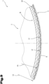
- einen Teilbereich des Kombi-Verpackungsbehälters nach den
Fig. 1 und 2 , im Querschnitt gemäß den Linien III-III inFig. 1 und vergrößerter Darstellung; - Fig. 4
- den Zuschnitt zur Bildung des Außenteils nach den
Fig. 1 , in unverformter, ebenflächiger Lage;bis 3 - Fig. 5
- ein weiteres Ausführungsbeispiel eines Zuschnitts zur Bildung des Außenteils mit einer anderen Ausbildung der zusätzlichen Stützvorrichtung, in unverformter, ebenflächiger Lage;
- Fig. 6
- ein weiteres Detail des Kombi-Verpackungsbehälters mit dem weiteren Ausführungsbeispiel des Zuschnitts nach
Fig. 5 , in Ansicht geschnitten und vergrößerter Darstellung.
- Fig. 1
- a combination packaging container with an inner container and an outer part with an additional support device, in elevation, partly in section;
- Fig. 2
- a detail of the combi packaging container after
Fig. 1 , in sectioned view and enlarged representation; - Fig. 3
- a part of the combination packaging container according to the
Fig. 1 and2 , in cross section along lines III-III inFig. 1 and enlarged view; - Fig. 4
- the cutting to form the outer part according to the
Fig. 1 to 3 , in an undeformed, flat position; - Fig. 5
- a further embodiment of a blank for forming the outer part with a different design of the additional support device, in an undeformed, flat position;
- Fig. 6
- another detail of the combination packaging container with the further embodiment of the blank according to
Fig. 5 , in sectioned view and enlarged representation.
Einführend sei festgehalten, dass in den unterschiedlich beschriebenen Ausführungsformen gleiche Teile mit gleichen Bezugszeichen bzw. gleichen Bauteilbezeichnungen versehen werden, wobei die in der gesamten Beschreibung enthaltenen Offenbarungen sinngemäß auf gleiche Teile mit gleichen Bezugszeichen bzw. gleichen Bauteilbezeichnungen übertragen werden können. Auch sind die in der Beschreibung gewählten Lageangaben, wie z.B. oben, unten, seitlich usw. auf die unmittelbar beschriebene sowie dargestellte Figur bezogen und sind diese Lageangaben bei einer Lageänderung sinngemäß auf die neue Lage zu übertragen.By way of introduction, it should be noted that in the variously described embodiments, identical parts are provided with identical reference symbols or component designations, whereby the disclosures contained throughout the description can be applied mutatis mutandis to identical parts with identical reference symbols or component designations. Furthermore, the positional information chosen in the description, such as top, bottom, side, etc., refers to the directly described and illustrated figure, and these positional information must be applied mutatis mutandis to the new position in the event of a change in position.
Der Begriff "insbesondere" wird nachfolgend so verstanden, dass es sich dabei um eine mögliche speziellere Ausbildung oder nähere Spezifizierung eines Gegenstands oder eines Verfahrensschritts handeln kann, aber nicht unbedingt eine zwingende, bevorzugte Ausführungsform desselben oder eine zwingende Vorgehensweise darstellen muss.The term "in particular" is understood below to mean that it may refer to a possible more specific embodiment or more detailed specification of an object or a method step, but does not necessarily have to represent a mandatory, preferred embodiment of the same or a mandatory procedure.
In ihrer vorliegenden Verwendung sollen die Begriffe "umfassend", "weist auf", "aufweisend", "schließt ein", "einschließlich", "enthält", "enthaltend" und jegliche Variationen dieser eine nicht ausschließliche Einbeziehung abdecken.As used herein, the terms "comprising," "comprises," "having," "includes," "including," "contains," "containing," and any variations thereof are intended to cover non-exclusive inclusion.
Als weiterer Begriff kann auch noch "wahlweise" verwendet werden. Darunter wird verstanden, dass dieser Verfahrensschritt oder diese Anlagenkomponente grundsätzlich vorhanden ist, jedoch je nach Einsatzbedingungen eingesetzt werden kann, dies jedoch nicht zwingend erfolgen muss.Another term that can also be used is "optional." This means that this process step or system component is generally present but can be used depending on the operating conditions, although this is not mandatory.
Die vorliegende Anmeldung stellt eine Weiterentwicklung der in der Beschreibungseinleitung bereits zum Stand der Technik genannten
In den
Der Innenbehälter 2 wird bevorzugt durch einen in einem Tiefziehvorgang hergestellten Bauteil gebildet, welcher rasch und vor allem in kurzer Zykluszeit herstellbar ist. Der Vorgang des Tiefziehens ist hinlänglich bekannt und wird deshalb nicht näher darauf eingegangen. Der Tiefziehvorgang eignet sich besonders dazu, um aus einer umzuformenden Schicht aus einem umformbaren Werkstoff mittels eines Tiefziehwerkzeuges den Innenbehälter 2 mit einer doch ausreichenden Wandstärke herzustellen, welche die Dichtheit während der Lagerung, Benutzung bis hin zur Entsorgung gewährleistet. Durch diesen Herstellvorgang können relativ dünne Wandstärken des Innenbehälters 2 gefertigt werden. Der Innenbehälter 2 kann aber auch mittels anderer Herstellverfahren ausgeformt werden, wie z.B. mittels eines Spritzgussvorganges.The
Durch die becher- bzw. schalenförmige Ausbildung des Innenbehälters 2 erstreckt sich in Axialrichtung zwischen dem offenen Ende 5 und dem mit dem Boden 3 verschlossenen Ende 7 eine Längsachse 8, welche bei symmetrischer Ausbildung auch eine Mittelachse darstellen kann. Im Bereich des Flansches 6 ist es möglich, eine nicht näher dargestellte Siegelplatine anzuordnen bzw. damit zu verbinden. In diesem Fall bildet der Flansch 6 einen Siegelflansch aus.Due to the cup- or bowl-shaped design of the
In Axialrichtung und somit in Richtung der Längsachse 8 weist der Innenbehälter 2 zwischen seinem offenen Ende 5, insbesondere dem Flansch 6, und dem Boden 3 eine Behälterhöhe 9 auf, wodurch in Abhängigkeit von den Querschnittsabmessungen das Aufnahmevolumen des Innenbehälters 2 festgelegt wird. Durch die Behälterhöhe 9 in Verbindung mit den Querschnittsabmessungen wird somit ein Aufnahmeraum des Innenbehälters 2 definiert.In the axial direction and thus in the direction of the
Als Behältermantel 4 wird jener Abschnitt des Innenbehälters 2 verstanden, welcher sich zwischen dem offenen Ende 5, insbesondere dem Flansch 6, und dem Boden 3 in überwiegend axialer Richtung erstreckt. Bevorzugt wird der Innenbehälter 2 mit seinem Behältermantel 4 derart ausgebildet, dass sich dieser ausgehend vom offenen Ende hin zum Boden bevorzugt konisch verjüngt.The
Weiters kann der Behältermantel 4 des Innenbehälters 2 in seinem dem Boden 3 benachbarten Umfangsabschnitt einen Hinterzug 10 aufweisen. Der Hinterzug 10 ist ebenfalls Teil des Behältermantels 4, ist jedoch im Axialschnitt gesehen bezüglich einer gedachten, geradlinig verlaufenden Verbindungslinie zwischen dem Flansch 6 und dem Boden 3 zu dieser nach innen versetzt angeordnet. Der Hinterzug 10 weist seinerseits zumindest zwei nicht näher bezeichnete Hinterzug-Wandabschnitte auf, wobei die beiden Hinterzug-Wandabschnitte im Axialschnitt gesehen bezüglich der Längsachse 8 eine andere Neigung bzw. Richtung aufweisen als der übrige Behältermantel 4. Dabei ist der Hinterzug 10, gegenüber der im Axialschnitt gesehen, geradlinig verlaufenden Anordnung des Behältermantels 4 zwischen dem Flansch 6 und dem Boden 3 nach innen und somit in Richtung des Aufnahmeraums versetzt angeordnet.Furthermore, the
Im Axialschnitt gesehen ist der unmittelbar an den Boden 3 anschließende, erste Hinterzug-Wandabschnitt überwiegend in Richtung der Behälterhöhe 9 hin auf das offene Ende 5 erstreckend angeordnet bzw. ausgebildet. Der weitere Hinterzug-Wandabschnitt erstreckt sich in überwiegend senkrechter Richtung bezüglich der Behälterhöhe 9, ausgehend von dem dem Boden 3 abgewendeten Ende des ersten Hinterzug-Wandabschnittes hin zum Behältermantel 4. Im vorliegenden Ausführungsbeispiel bildet der weitere Hinterzug-Wandabschnitt eine Stapelschulter aus. Diese Stapelschulter dient dazu, dass ein gleichartiger Kombi-Verpackungsbehälter 1 mit seinem Boden 3, insbesondere dem randseitigen Übergangsabschnitt zwischen dem Boden 3 und dem Behältermantel 4, sich darauf abstützen kann.Viewed in axial section, the first rear-drawn wall section, which directly adjoins the
Weiters kann der Innenbehälter 2 im unmittelbaren Übergangsbereich zwischen dem Boden 3 und dem Behältermantel 4, insbesondere zwischen dem Boden 3 und dem Hinterzug, eine auf die von der Längsachse 8 abgewendete Seite vorragende Schulter 11 bzw. einen Wulst aufweisen.Furthermore, the
Der Kombi-Verpackungsbehälter 1 umfasst weiters ein Außenteil 12, welches manschettenförmig oder mantelförmig ausgebildet ist und den Innenbehälter 2 im Bereich seines Behältermantels 4 zumindest abschnittsweise oder bereichsweise umgibt.The
Die zuvor beschriebene Schulter 11 kann beispielsweise dazu dienen, das manschettenförmige Außenteil 12 am Innenbehälter 2 zu haltern. In diesem Fall stützt sich das manschettenförmige Außenteil 12 mit seiner dem Boden 3 des Innenbehälters 2 zugewendeten ersten Stirnseite 19 an dieser im Übergangsbereich ausgebildeten Schulter 11 ab. Die Schulter 11 kann damit auch als Rastmittel für die Halterung des Außenteils 12 am Innenbehälter 2 bezeichnet werden. Die Stirnseite 19 bildet in deren Längserstreckung eine Stirnkante aus, welche in der gefügten Stellung zumindest abschnittsweise einen Abstützbereich definiert und an der Schulter anliegend abgestützt wird. Je nach radialem Überstand der Schulter 11 und der den toleranzbedingten Abmessung des Außenteils 12 kann es zu einem ungewollten Ablösen des Außenteils 12 vom Innenbehälter 2 kommen.The previously described
Ein weiteres Rastmittel im Bereich des offenen Endes 5 kann beispielsweise der Flansch 6 darstellen. Weiters umfasst das manschettenförmige Außenteil 12 eine zweite Stirnseite 20, welche ihrerseits dem offenen Ende 5 oder dem Flansch 6 zugewendet ist.A further locking means in the region of the
Das manschettenförmige Außenteil 12 wird bevorzugt aus einem Zellulose-Werkstoff, wie einem Kartonmaterial, mit einer ausreichenden Festigkeit in Bezug auf die Aufnahme und Übertragung von insbesondere axial wirkenden Druckkräften gebildet und aus einem ebenflächigen Zuschnitt 13 zu einem Mantel gewickelt, wie dies bereits hinlänglich bekannt ist. Der Zuschnitt 13 wird zumeist in seiner unverformten ebenen Lage bedruckt sowie gegebenenfalls noch mit einer zusätzlichen Beschichtung versehen. Als Werkstoff wird zumeist ein Zellulosematerial verwendet, wobei dies auch ein im Recyclingverfahren hergestellter Karton oder Starkpapier sein kann. Wird eine Schicht bzw. Lage des Außenteils 12 aus einem Recyclingmaterial gebildet, kann auf zumindest einer der Oberflächen eine zusätzliche Schicht aus einem hochwertigeren Papier angeordnet bzw. damit verbunden sein. Diese zusätzliche Schicht dient einer einwandfreien Bedruckung zur Herstellung von Verzierungen, Beschriftungen sowie Produktinformationen.The sleeve-shaped
Das manschettenartige bzw. mantelartige Außenteil 12 führt zu einem zusätzlichen Verstärkung- bzw. Versteifungseffekt des Innenbehälters 2 und somit des gesamten Kombi-Verpackungsbehälters 1.The sleeve-like or jacket-like
Damit ist zum einen eine hohe Festigkeit und gute Wärmeisolierung und zum anderen ein optimaler Lichtschutz für den Inhalt des Verpackungsbehältnisses gegeben.This provides high strength and good thermal insulation on the one hand, and optimal light protection for the contents of the packaging container on the other.
Dabei kann insbesondere auch vorgesehen sein, dass der Karton im Bereich der Schnittkanten zusätzlich mit einem wasserabweisenden Material beschichtet oder versiegelt wird. Dies ist besonders dann von Vorteil, wenn die Kombi-Verpackungsbehälter 1 einem erhöhten Feuchtigkeitszutritt ausgesetzt sind. Durch die Beschichtung des für das Außenteil 12 verwendeten Kartons mit einer wasserabweisenden Schicht wird nämlich verhindert, dass es in einer feuchten Umgebung zu einem Aufquellen des Kartons und schließlich zu einem Ablösen vom Behältermantel 4 des Kombi-Verpackungsbehälters 1 kommt.In particular, it can also be provided that the cardboard is additionally coated or sealed with a water-repellent material in the area of the cut edges. This is particularly advantageous when the
Das manschettenförmige Außenteil 12 ist aus dem zumeist ebenflächigen Zuschnitt 13 zu einem Mantel gewickelten ist. Durch das Wickeln des Zuschnitts werden dann einander zugewendete Endabschnitte 14, 15 in einem vereinfacht dargestellten Überlappungsbereich 16 miteinander verbunden. Dies erfolgt durch eine sogenannte Überlappungsnaht, mittels welcher der erste Endabschnitt 14 und der zweite Endabschnitt 15 z.B. mittels eines Klebemittels, aneinander haften. Das Wickeln und das anschließende Verbinden der beiden Endabschnitte 14, 15 kann dabei, wie dies bereits aus dem Stand der Technik hinlänglich bekannt ist, zum Beispiel durch Verkleben erfolgen. Als Beispiel wird hier auf die
Das Außenteil 12 weist weiters die erste Stirnseite 19 und die zweite Stirnseite 20 auf, wobei die beiden Stirnseiten 19, 20 voneinander beabstandet sind sowie im aufgerichteten Zustand eine Bauhöhe 21 des Mantels definieren. Die bereits zuvor beschriebene Längsachse 8 kann auch die gemeinsame Längsachse für das Außenteil 12 definieren, insbesondere dann, wenn sich das Außenteil 12 in seiner montierten Lage am Innenbehälter 2 befindet. Zumeist ist die Bauhöhe 21 des Mantels geringfügig geringer als die Behälterhöhe 9 des Innenbehälters 2 in der gleichen Raumrichtung - nämlich in Richtung der Längsachse 8.The
Nachfolgend wird eine mögliche, jedoch nicht zwingende Anordnung und/oder Ausbildung für die Trennung des Außenteils 12 vom Innenbehälter 2 beschrieben. Dabei handelt es sich um einen sogenannten Solltrennbereich 22, welcher im Werkstoff oder Material des Außenteils 12 angeordnet und ausgebildet ist. Die nachfolgende detaillierte Beschreibung des Solltrennbereichs 22 entspricht dabei jener Ausbildung, wie diese bereits in der
Um eine definierte Durchtrennung und damit verbunden eine nachfolgend getrennte Entsorgung von Innenbehälter 2 und Außenteil 12 für einen Verbraucher zu ermöglichen, ist zumindest ein im Mantel des Außenteils 12 ausgebildeter Solltrennbereich 22 vorgesehen. Der Solltrennbereich 22 umfasst hier einen ersten Trennabschnitt 23, einen zweiten Trennabschnitt 24 sowie ein Betätigungsmittel 25 zum Start und dem Beginn des Durchtrennvorganges des Solltrennbereichs 22 entlang der beiden Trennabschnitte 23, 24. Das Betätigungsmittel 25 ist in Richtung der Bauhöhe 21 des Mantels gesehen zwischen den beiden Stirnseiten 19, 20 angeordnet. Dabei ist es vorteilhaft, wenn das Betätigungsmittel 25 in etwa mittig zwischen den beiden in Richtung der Bauhöhe 21 voneinander beabstandeten Stirnseiten 19, 20 angeordnet ist, wobei dies im Wesentlichen der halben Bauhöhe 21 entspricht. Die Angabe "mittig" bezieht sich beim Betätigungsmittel 25 auf dessen halbe Abmessung in Richtung der Bauhöhe 21 oder der Längsachse 8. Die beiden Trennabschnitte 23, 24 sind beidseits des Betätigungsmittels 25 vorgesehen und erstrecken sich jeweils in Richtung auf die jeweilige Stirnseite 19, 20.In order to enable a defined severing and, associated with this, subsequent separate disposal of the
In Richtung der Bauhöhe 21 des Mantels gesehen sind die beiden Trennabschnitte 23, 24 des Solltrennbereichs 22 jeweils von den beiden Stirnseiten 19, 20 aufeinander zulaufend ausgerichtet und definieren damit zwischen sich eine gedachte, geradlinig verlaufende Verbindungslinie 26, wobei diese in strichlierten Linien dargestellt ist. Die aufeinander zulaufende Ausrichtung der beiden Trennabschnitte 23, 24 ist jeweils in Richtung auf das Betätigungsmittel 25 bezogen. Die beiden Trennabschnitte 23, 24 können dabei entweder in Richtung der Bauhöhe 21 des Mantels gesehen zueinander fluchtend ausgerichtet sein oder aber auch geringfügig geneigt bezüglich der ersten Längskante 17 hin in Richtung auf das zwischen diesen befindliche Betätigungsmittel 25 verlaufen. Durch diese geringfüge Neigung kann der Auftrennvorgang nach dem Auftrennen der beiden Trennabschnitte 23, 24 hin zu den beiden Stirnseiten 19, 20 noch zusätzlich verbessert werden.Viewed in the direction of the
Je nach Ausbildung der später noch näher beschriebenen Solltrennstellen wird die gedachte Verbindungslinie 26 in einem Mittel der Solltrennstellen verlaufend angenommen. Das Betätigungsmittel 25 definiert seinerseits einen Erfassungsabschnitt 27 mit einem in Richtung der Bauhöhe 21 voneinander beabstandet befindlichen ersten Erfassungsabschnitt-Ende 28 und einem zweiten Erfassungsabschnitt-Ende 29. Damit sind die beiden Erfassungsabschnitt-Enden 28, 29 in Richtung der Bauhöhe 21 des Mantels gesehenen in einem Abstand 30 voneinander distanziert angeordnet bzw. enden dort. Weiters ist noch zu ersehen, dass der Erfassungsabschnitt 27 des Betätigungsmittels 25 außerhalb des Überlappungsbereichs 16 angeordnet oder ausgebildet ist.Depending on the design of the predetermined separation points, which will be described in more detail later, the imaginary connecting
Es ist hier eine Anordnung des Betätigungsmittels 25 vorgesehen, bei welcher der Erfassungsabschnitt 27 in Umfangsrichtung gesehen bezüglich der aufeinander zulaufend ausgerichteten Trennabschnitte 23, 24 des Solltrennbereichs 22 und der zwischen diesen gedachten geradlinigen Verbindungslinie 26 um einen Versatz 31 seitlich davon distanziert angeordnet oder ausgebildet ist. Der Versatz 31 kann einen Wert aufweisen, welcher ausgewählt ist aus einem Wertebereich mit einer unteren Grenze von 1,0mm und einer oberen Grenze von 10,0mm. Bevorzugt kann der Wertebereich eine untere Grenze von 2,0mm und eine obere Grenze von 6,0mm aufweisen.An arrangement of the actuating means 25 is provided here in which the
Der erste Trennabschnitt 23 weist seinerseits ein dem Betätigungsmittel 25 zugewendetes erstes Ende 32 auf, wobei der zweite Trennabschnitt 24 ein dem Betätigungsmittel 25 zugewendetes zweites Ende 33 aufweist. Im Bereich der gedachten Verbindungslinie 26 zwischen den beiden Enden 32, 33 ist aufgrund des vorgesehenen seitlichen Versatzes 31 des Betätigungsmittels 25 der Mantel unterbrechungslos ausgebildet. Die Anordnung der beiden in Richtung der Bauhöhe 21 voneinander beabstandeten Enden 32, 33 der Trennabschnitte 23, 24 bezüglich des das Betätigungsmittel 25 bildenden Erfassungsabschnitts 27 ist derart gewählt, dass das erste Erfassungsabschnitt-Ende 28 des Erfassungsabschnitts 27 das benachbart befindliche erste Ende 32 des ersten Trennabschnitts 23 auf die vom zweiten Trennabschnitt 24 abgewendete Seite übergreift. Durch den seitlichen Versatz 31 des Erfassungsabschnitts 27 auf die vom Überlappungsbereich 16 abgewendete Seite bildet sich ein erster Solltrennabschnitt 34 in Umfangsrichtung gesehen im Mantel des Außenteils 12 zwischen dem ersten Erfassungsabschnitt-Ende 28 und dem ersten Ende 32 des ersten Trennabschnitts 23 aus.The
Es ist auch noch vorgesehen, dass das zweite Erfassungsabschnitt-Ende 29 des Erfassungsabschnitts 27 das benachbart befindliche zweite Ende 33 des zweiten Trennabschnitts 24 auf die vom ersten Trennabschnitt 23 abgewendete Seite übergreift. Damit wird analog zum ersten Solltrennabschnitt 34 auch zwischen dem zweiten Erfassungsabschnitt-Ende 29 und dem zweiten Ende 33 des zweiten Trennabschnitts 24 in Umfangsrichtung gesehen ein zweiter Solltrennabschnitt 35 im Mantel des Außenteils 12 ausgebildet. Die beiden Solltrennabschnitte 34, 35 sind durch die reduzierte Abmessung des Mantelmaterials zwischen dem jeweiligen Erfassungsabschnitt-Ende 28 oder 29 und dem jeweiligen Ende 32 oder 33 gebildet. Die beiden Enden 32 und 33 der Trennabschnitte 23, 24 sind näher zueinander angeordnet als die beiden durch den Abstand 30 voneinander beabstandeten Erfassungsabschnitt-Enden 28 und 29.It is also provided that the second
Damit wird es für einen Benutzter des Kombi-Verpackungsbehälters 1 möglich, das Betätigungsmittel 25 mit seinem Erfassungsabschnitt 27 zu erfassen, anschließend die beiden Solltrennabschnitte 34 35 ausgehend vom Erfassungsabschnitt 27 bis hin zu den jeweiligen Enden 32, 33 der beiden Trennabschnitte 23, 24 aufzutrennen und nachfolgend die beiden Trennabschnitte 23, 24 bis zum vollständigen Durchtrennen des Mantels aufzutrennen. Damit kann das Außenteil 12 einfach vom Innenbehälter 2 abgetrennt werden und eine sortenreine Entsorgung erfolgen. Die beiden Solltrennabschnitte 34, 35 bilden jeweils Startabschnitte für die Auftrennung der beiden Trennabschnitte 23, 24 aus.This makes it possible for a user of the
Jeder der beiden Trennabschnitte 23, 24 umfasst mehrere in einer Reihe hintereinander angeordnete Solltrennstellen, welche zumeist als Perforationen, insbesondere auch als kurze Schnitte, im Werkstoff des Außenteils 12 ausgebildet sind.Each of the two separating
Bei diesem Ausführungsbeispiel ist gezeigt, dass die Form und Lage der Solltrennstellen zueinander unterschiedlich gewählt sein kann. Deshalb werden jene Solltrennstellen, welche unmittelbar benachbart zu den jeweiligen Erfassungsabschnitt-Enden 28, 29 angeordnet sind, als erste Solltrennstellen 36 bezeichnet. Die jeweils nachfolgend hin Richtung auf eine der beiden Stirnseiten 19, 20 vorgesehenen weiteren Solltrennstellen werden als zweite Solltrennstellen 37 und dritte Solltrennstellen 38 bezeichnet.In this embodiment, it is shown that the shape and position of the predetermined separation points can be selected differently from one another. Therefore, those predetermined separation points that are located directly adjacent to the respective detection section ends 28, 29 are referred to as first predetermined separation points 36. The further predetermined separation points provided subsequently towards one of the two end faces 19, 20 are referred to as second predetermined separation points 37 and third predetermined separation points 38.
Die Solltrennstellen 36, 37, 38 sind bezüglich einer mittig und in normaler Ausrichtung zu der Längsachse 8 ausgerichteten Ebene 39 - siehe
Weiters ist noch im linken unteren Eckbereich des im Schnitt gezeigten Kombi-Verpackungsbehälters 1 in der
Bei diesem hier gezeigten ersten Ausführungsbeispiel umfasst die zusätzliche Stützvorrichtung 40 zumindest ein Stützelement 41, bevorzugt jedoch mehrere entlang der ersten Stirnseite 19 voneinander beabstandet angeordnete Stützelemente 41, welche beim manschettenförmigen Außenteil 12 über den Umfang verteilt angeordnet sind. Die einzelnen Stützelemente 41 werden durch Umformung oder Prägung in den Werkstoff des Zuschnitts 13 eingeformt und sind damit jeweils integraler Bestandteil des Zuschnitts 13. Die Stützelemente 41 werden dabei ausgehend von einer Außenfläche 42 des Außenteils 12 in Richtung auf eine Innenfläche 43 eingeformt und somit ausgebildet. Somit ragen diese in radialer Richtung über die unverformte Innenfläche 43 in Richtung auf die Längsachse 8 vor. Der Überstand kann dabei einen Wert aufweisen, der aus einem Wertebereich stammt, dessen untere Grenze 0,05 mm, insbesondere 0,1 mm, und dessen obere Grenze 0,5 mm, insbesondere 0,2 mm, beträgt.In this first exemplary embodiment shown here, the
Eine lichte innere Abmessung 44 der von den Stützelementen 41 gebildeten zusätzlichen Stützvorrichtung 40 ist damit kleiner als eine Innenabmessung 45 des Außenteils 12 in seiner unverformten Ausbildung ohne der Stützelemente 41. Durch das Einformen des zumindest einen Stützelements 41 wird auch die erste Stirnseite 19 entlang ihres Längsverlaufs umgeformt und bildet damit auch eine Abstützfläche für das Außenteil 12 an der Schulter 11 aus. Der Längsverlauf kann auch in Form einer Längswellung ausgebildet werden.A clear
Das Stützelement 41 weist oder die Stützelemente 41 weisen eine Längserstreckung ausgehend von der ersten Stirnseite 19 in Richtung auf die zweite Stirnseite 20 auf. So reicht das Stützelement 41 oder reichen die Stützelemente 41 bis an die erste Stirnseite 19 heran. Die Länge des zumindest einen Stützelements 41 kann z.B. wenige Millimeter betragen und hängt von der Größe und Ausbildung des Hinterzugs 10 ab. Als mögliche Beispiele können 2 mm bis 15 mm, bevorzugt 5 mm bis 10 mm angeführt werden. Die Querschnittsform des Stützelements 41 oder der Stützelemente 41 ist nur beispielhaft dargestellt. Es wäre anstatt der hier eher eckigen Querschnittsform auch eine ausgerundete oder bogenförmige Querschnittsform denkbar.The
In der
Der zuvor beschriebene Solltrennbereich 22 ist hier nicht näher dargestellt, kann aber auch so vorgesehen sein, wie dies zuvor bereits als mögliche und wahlweise Variante beschrieben worden ist. Weiters ist die Orientierung der einzelnen Stützelemente 41 ausgehend von der dem Boden zuwendbaren ersten Stirnseite 19 hin in Richtung auf die zweite Stirnseite 20 hier besser zu ersehen. Durch den bogenförmig gekrümmten Längsverlauf der beiden Stirnseiten 19, 20 und deren gemeinsames Zentrum (Mittelpunkt des Radius), weisen auch die einzelnen Stützelemente 41 einen auf das Zentrum ausgerichteten Längsverlauf auf.The previously described
In den
Dabei sei erwähnt, dass es auch hier wiederum wahlweise möglich ist, den zuvor bereits detailliert beschriebenen Solltrennbereich 22 vorzusehen oder auszubilden. Der besseren Übersichtlichkeit halber und zur Vermeidung von unnötigen Wiederholungen wurde auf die Darstellung und Beschreibung desselben verzichtet.It should be noted that here, too, it is optionally possible to provide or form the
Der Zuschnitt 13 und das daraus gebildete Außenteil 12 umfasst wiederum die zusätzliche Stützvorrichtung 40, welche allerdings eine zum zuvor beschriebenen Ausführungsbeispiel dazu unterschiedliche Ausbildung aufweist. So umfasst die zusätzliche Stützvorrichtung 40 zur Ausbildung derselben zumindest einen Umformabschnitt 46, welcher ebenfalls in den Werkstoff des Zuschnitts 13 eingeformt ist. Im Gegensatz zu dem zuvor beschriebenen Ausführungsbeispiel ist der zumindest eine Umformabschnitt 46 ausgehend von der Innenfläche 43 des Außenteils 12 in Richtung auf seine Außenfläche 42 hin eingeformt. Weiters ist der zumindest eine Umformabschnitt 46 von der ersten Stirnseite 19 in Richtung auf die gegenüberliegende zweite Stirnseite 20 beabstandet angeordnet.The blank 13 and the
Im Axialschnitt gesehen kann der zumindest eine Umformabschnitt 46 einen zumeist nach außen gekrümmt ausgebildeten Längsverlauf aufweisen. Anschließend an den zumindest einen Umformabschnitt 46 ist in Richtung auf die erste Stirnseite 19 ein daran befindlicher Endabschnitt 47 vorgesehen. Somit ist benachbart zu jedem Umformabschnitt 46 auch ein entsprechender Endabschnitt 47 ausgebildet oder angeordnet. Der Endabschnitt 47 kann seinerseits in Richtung auf die Längsachse 8 hin geneigt verlaufend ausgerichtet sein.Viewed in axial section, the at least one forming
Wie nun besser aus der
Durch das bewusste zusätzliche Umformen des Zuschnitts 13 im Bereich seiner ersten Stirnseite 19 wird erreicht, dass der zuvor beschriebene Endabschnitt 47 mit der daran befindlichen ersten Stirnseite 19 das zumindest eine Stützelement 41 bildet oder definiert. Das zumindest eine Stützelement 41 definiert in der aufgerichteten Stellung des Zuschnitts 13 zu dem Außenteil 12 wiederum die lichte innere Abmessung 44, welche kleiner ist als eine Innenabmessung 45 des Außenteils 12 in seiner unverformten Ausbildung ohne des Umformabschnitts 46. Das bodenseitige Ende des Außenteils 12 ist in der unverformten Stellung in strichlierten Linien in der
Durch die Ausbildung und Einformung des Umformabschnitts 46 kann es erforderlich sein, die unverformte Höhe zwischen der ersten und zweiten Stirnseite 19, 20 etwas länger auszubilden, um nachfolgend einerseits die Abstützung an der Schulter 11 zu erzielen und andererseits bis unmittelbar benachbart bis hin zum Flansch 6 den Behältermantel 4 abdecken zu können.Due to the formation and shaping of the forming
Es wäre aber auch möglich, den Umformabschnitt 46 von der Außenfläche 42 in Richtung auf die Innenfläche 43 einzuformen und damit eine Art von Knick auszubilden.However, it would also be possible to form the forming
Zur gegenseitigen Verbindung der bei der Bildung des Mantels einander zugewendeten Endabschnitte 14, 15 des zuvor ebenflächigen Zuschnitts 13 wird in dem auszubildenden Überlappungsbereich 16 bevorzugt ein Haftmittel oder ein Klebemittel eingesetzt oder verwendet. Dieses kann auf einen der Endabschnitte 14 oder 15 oder auch auf beide derselben aufgebracht werden, wie dies hinlänglich bekannt ist.To mutually bond the
Eine große Herausforderung stellt das Trennen, das Entsorgen und das nachfolgende Recycling der unterschiedlichen Werkstoffe dar. Der Innenbehälter 2 ist zumeist aus einem Kunststoff oder einem abbaubaren und in einem Thermoformprozess umformbaren Werkstoff gebildet. Das Außenteil 12 ist bevorzugt aus einem Zellulosewerkstoff gebildet. Der Zuschnitt 13 kann weiters auf zumindest einer seiner Flachseiten, nämlich der Außenfläche 42 und/oder der Innenfläche 43, mit einem Druckbild versehen sein.The separation, disposal, and subsequent recycling of the different materials poses a major challenge. The
Da von den Konsumenten oder Verbrauchern der Trennvorgang des Außenteils 12 von Innenbehälter 2 zumeist nicht oder nur teilweise durchgeführt wird, kann hier weiters vorgesehen sein, dass das im Überlappungsbereich 16 verwendete Haftmittel je nach der darauf einwirkenden Kraftrichtung, insbesondere der Trennrichtung, zueinander unterschiedliche Haftkraftwerte aufweist.Since the separation process of the
In Umfangsrichtung gesehen und somit auf Zug oder Scherung, soll das Haftmittel einen ausreichend hohen Haftkraftwert aufweisen, um bei den üblichen Belastungen einen ausreichenden gegenseitigen Halt der beiden Endabschnitte 14, 15 aneinander zu gewährleisten.Viewed in the circumferential direction and thus in tension or shear, the adhesive should have a sufficiently high adhesive force value to ensure sufficient mutual hold of the two
Wird jedoch eine Druckkraft -F- auf den zu trennenden Kombi-Verpackungsbehälter 1 aufgebracht, weist das Haftmittel einen zweiten Haftkraftwert auf, welcher unterschiedlich zum ersten Haftkraftwert ist. Der erste Haftkraftwert soll größer sein als der zweite Haftkraftwert. Die Druckkraft -F- kann in den unterschiedlichsten Richtungen auf den Kombi-Verpackungsbehälter 1 aufgebracht werden und wird zumindest teilweise in eine den Überlappungsbereich 16 zumindest teilweise auftrennende Auftrennkraft umgewandelt. Dabei wird der zweite Haftkraftwert überschritten und die beiden zuerst vom Haft- oder Klebemittel zusammengehaltenen Endabschnitte 14, 15 lösen sich voneinander zumindest abschnittsweise.However, if a compressive force -F- is applied to the
So kann z.B. ein Zusammendrücken in radialer Richtung und/oder auch in axialer Richtung durchgeführt werden. Dabei wird der gesamte Kombi-Verpackungsbehälter 1 räumlich verformt. Bei einer Druckkraft -F- in axialer Richtung knickt das Außenteil 12 und auch der Behältermantel 4 in Richtung auf die Längsachse 8 hinein und es kann damit aufgrund des geringeren Haftkraftwerts in dieser Kraftrichtung die Auftrennung des Überlappungsbereichs 16 erfolgen oder durchgeführt werden.For example, compression can be performed in the radial and/or axial directions. This spatially deforms the entire
Durch das Vorsehen oder Ausbilden der zusätzlichen Stützvorrichtung 40 im unmittelbar benachbarten Randbereich zur ersten Stirnseite 19 kann das manschettenförmige Außenteil 12 unter Ausschluss eines zusätzlichen Klebemittels mittels seiner zusätzlichen Stützvorrichtung 40 an der Schulter 11 des Innenbehälters 2 in Axialrichtung noch besser und sicherer abgestützt werden. Der bislang aus Sicherheitsgründen zusätzlich angebrachte Klebepunkt zwischen der Innenfläche 43 des Außenteils 12 und dem Behältermantel 4 kann damit entfallen und braucht nicht mehr vorgesehen werden. So kann beim Auftrennen des Überlappungsbereichs 16 mit dem dabei eingesetzten Haftmittel und/oder dem Auftrennen des Solltrennbereichs 22 eine noch ungewollte Haftverbindung zwischen dem Außenteil 12 und dem Innenbehälter 2 vermieden werden.By providing or forming the
Damit kann der Benutzer des Kombi-Verpackungsbehälters 1 auf die Durchführung des Auftrennvorgangs verzichten und kann den kompletten Kombi-Verpackungsbehälter 1 der Entsorgung zuführen. Der Auftrennvorgang des Solltrennbereichs 22 wird dann bei der Abholung und/oder bei der Abfallentsorgung maschinell durch eine Presse oder eine Quetschvorrichtung durchgeführt.This allows the user of the
Weiters wäre es zur Durchführung des Trennvorgangs durch eine Person noch möglich, dass der Kombi-Verpackungsbehälter entweder mit seinem verschlossenen Ende oder mit seinem offenen Ende des Innenbehälters auf eine Abstützfläche abgestellt und anschließend die Druckkraft -F- auf das von der Abstützfläche abgewendete Ende in Richtung auf die Abstützfläche ausgeübt wird. Je nach Anordnung und Aufstellung des Kombi-Verpackungsbehälters kann so einfach die Druckkraft z.B. mit menschlicher Kraft, auf den Kombi-Verpackungsbehälter aufgebracht und in diesen eingeleitet werden. Die Verletzungsgefahr kann bei jener Anordnung, bei welcher die Druckkraft auf den Boden eingebracht wird, minimiert werden.Furthermore, to allow a single person to perform the separation process, it would be possible to place the combination packaging container on a support surface, either with its closed end or with the open end of the inner container, and then apply the compressive force -F- to the end facing away from the support surface in the direction of the support surface. Depending on the arrangement and setup of the combination packaging container, the compressive force can be easily applied to the combination packaging container and introduced into it, e.g., using human force. The risk of injury can be minimized with an arrangement in which the compressive force is applied to the floor.
Es wäre auch noch möglich, die Druckkraft -F- in einer parallelen Ausrichtung bezüglich einer sich zwischen dem offenen Ende und dem verschlossenen Ende erstreckenden Längsachse oder in einer bezüglich der Längsachse dazu winkeligen Ausrichtung auf den Kombi-Verpackungsbehälter auszuüben. Damit kann die Druckkraft bei einer parallelen Krafteinleitung einfach in eine in überwiegend radialer Richtung wirkende Aufrisskraft zumindest zum größten Anteil umgelenkt werden, was zu einem Aufplatzen des Außenteils in seinem Überlappungsbereich führt. Bei einer davon abweichenden Krafteinleitungsrichtung kann ebenfalls durch die räumliche Umformung das Auftrennen des Überlappungsbereichs bewirkt werden.It would also be possible to exert the compressive force -F- on the combination packaging container in a parallel orientation with respect to a longitudinal axis extending between the open end and the closed end, or in an orientation angular to the longitudinal axis. Thus, with a parallel force application, the compressive force can be easily redirected, at least for the most part, into a tearing force acting in a predominantly radial direction, which leads to the outer part bursting open in its overlapping area. If the force application direction deviates from this, the spatial deformation can also cause the overlapping area to separate.
Wird auch noch der zuvor beschriebene Solltrennbereich vorgesehen, kann wahlweise der Trennvorgang des Kombi-Verpackungsbehälters 1 in seine unterschiedlichen Komponenten durchgeführt werden. Dies entweder durch eine Person oder auch im Zuge des Sammel- und Entsorgungsvorgangs.If the previously described separation area is also provided, the separation process of the
Die Ausführungsbeispiele zeigen mögliche Ausführungsvarianten, wobei an dieser Stelle bemerkt sei, dass die Erfindung nicht auf die speziell dargestellten Ausführungsvarianten derselben eingeschränkt ist, sondern vielmehr auch diverse Kombinationen der einzelnen Ausführungsvarianten untereinander möglich sind und diese Variationsmöglichkeit aufgrund der Lehre zum technischen Handeln durch gegenständliche Erfindung im Können des auf diesem technischen Gebiet tätigen Fachmannes liegt.The embodiments show possible embodiments, whereby it should be noted at this point that the invention is not limited to the specifically illustrated embodiments thereof, but rather various combinations of the individual embodiments with one another are also possible and this possibility of variation lies within the skill of the person skilled in the art in this technical field due to the teaching of technical action by means of the objective invention.
Der Schutzbereich ist durch die Ansprüche bestimmt. Die Beschreibung und die Zeichnungen sind jedoch zur Auslegung der Ansprüche heranzuziehen. Einzelmerkmale oder Merkmalskombinationen aus den gezeigten und beschriebenen unterschiedlichen Ausführungsbeispielen können für sich eigenständige erfinderische Lösungen darstellen. Die den eigenständigen erfinderischen Lösungen zugrundeliegende Aufgabe kann der Beschreibung entnommen werden.The scope of protection is determined by the claims. However, the description and drawings must be used to interpret the claims. Individual features or combinations of features from the various embodiments shown and described may represent independent inventive solutions. The problem underlying the independent inventive solutions can be derived from the description.
Sämtliche Angaben zu Wertebereichen in gegenständlicher Beschreibung sind so zu verstehen, dass diese beliebige und alle Teilbereiche daraus mitumfassen, z.B. ist die Angabe 1 bis 10 so zu verstehen, dass sämtliche Teilbereiche, ausgehend von der unteren Grenze 1 und der oberen Grenze 10 mit umfasst sind, d.h. sämtliche Teilbereiche beginnen mit einer unteren Grenze von 1 oder größer und enden bei einer oberen Grenze von 10 oder weniger, z.B. 1 bis 1,7, oder 3,2 bis 8,1, oder 5,5 bis 10.All information on value ranges in this description is to be understood as including any and all sub-ranges thereof, e.g. the
Der Ordnung halber sei abschließend darauf hingewiesen, dass zum besseren Verständnis des Aufbaus Elemente teilweise unmaßstäblich und/oder vergrößert und/oder verkleinert dargestellt wurden.For the sake of clarity, it should finally be pointed out that, in order to better understand the structure, some elements have been shown out of scale and/or enlarged and/or reduced in size.
Claims (13)
- A combination packaging container (1) comprising a cup-shaped inner container (2) with a container jacket (4), a bottom (3), a flange (6), an undercut (10) located in the bottom region of the container jacket (4), wherein the inner container (2) has a shoulder (11) or bead projecting on the side facing away from the longitudinal axis (8) in the immediate transition region between the bottom (3) and the container jacket (4), as well as a sleeve-shaped outer part (12), which at least partially surrounds the inner container (2) on its container jacket (4),- wherein the outer part (12) is formed from a blank cut (13), said blank cut (13) being wound into a jacket in its raised state, and a first end portion (14) and facing it a second end portion (15) of the jacket are connected to one another in an overlapping region (16),- wherein the outer part (12) further has a first end face (19) and a second end face (20), the two end faces (19, 20) spaced apart from one another, and in the raised state, defining a structural height (21) of the jacket with a longitudinal axis (8) extending in the direction of the structural height (21), wherein the first end face (19) defines a support region in sections at least and, furthermore, the first end face (19) can face the bottom (3) and the second end face (20) the open end (5) of the inner container (2),
whereinthe sleeve-shaped outer part (12), with its first end face (19) facing the bottom (3) of the inner container (2), is supported by the former in the shoulder (11) configured in the transition region,characterized in that,- an additional support device (40) is provided on the outer part (12), said additional support device (40) being arranged or formed in the region of the first end face (19) of the outer part (12) formed from the blank cut (13), and- the additional support device (40) defines a clear inner dimension (44), which is smaller than an internal dimension (45) of the outer part (12) in its undeformed configuration in the region of the first end face (19). - The combination packaging container (1) according to Claim 1, characterized in that the additional support device (40) comprises at least one support element (41) and the at least one support element (41) defines the clear inner dimension (44).
- The combination packaging container (1) according to Claim 2, characterized in that the at least one support element (41) is molded into the material of the blank cut (13) starting from an outer surface (42) of the outer part (12) in the direction of an inner surface (43) and projects in the radial direction beyond the undeformed inner surface (43) in the direction of the longitudinal axis (8).
- The combination packaging container (1) according to Claim 2 or 3, characterized in that the at least one support element (41) has a longitudinal extension starting from the first end face (19) in the direction of the second end face (20).
- The combination packaging container (1) according to one of Claims 2 to 4, characterized in that a plurality of support elements (41) are provided and the support elements (41) are arranged spaced apart from one another along the first end face (19) in the circumferential direction.
- The combination packaging container (1) according to Claim 1, characterized in that the additional support device (40) comprises at least one forming portion (46), said forming portion (46) being molded into the material of the blank cut (13) starting from an inner surface (43) of the outer part (12) in the direction of an outer surface (42), and the at least one forming portion (46) is arranged at a distance from the first end face (19).
- The combination packaging container (1) according to Claim 6, characterized in that the at least one forming portion (46), viewed in axial section, has a preferably curved longitudinal extension and an end portion (47) adjoining the forming portion (46) in the direction of the first end face (19) oriented so as to be inclined in the direction of the longitudinal axis (8).
- The combination packaging container (1) according to Claim 6 or 7, characterized in that the at least one forming portion (46) has a parallel longitudinal extension in relation to the first end face (19).
- The combination packaging container (1) according to one of the Claims 6 to 8, characterized in that the forming portion (46) is arranged to extend continuously in the circumferential direction along the first end face (19).
- The combination packaging container (1) according to one of the Claims 6 to 8, characterized in that a plurality of forming portions (46) are provided and the forming portions (46) are arranged spaced apart from one another in the circumferential direction along the first end face (19).
- The combination packaging container (1) according to one of the preceding claims, characterized in that an adhesive is provided in the overlapping region (16) between the two end portions (14, 15), said adhesive having a first adhesive force value viewed in the circumferential direction and having a second adhesive force value in the radial direction, wherein the first adhesive force value is greater than the second adhesive force value.
- The combination packaging container (1) according to one of the preceding claims, characterized in that at least one target separation region (22) is formed or provided in the jacket of the outer part (12).
- The combination packaging container (1) according to Claim 1, characterized in that the sleeve-shaped outer part (12) is supported in the axial direction on the shoulder (11) of the inner container (2) by means of its additional support device (40) without using an additional adhesive.
Priority Applications (1)
| Application Number | Priority Date | Filing Date | Title |
|---|---|---|---|
| RS20250469A RS66794B1 (en) | 2021-02-25 | 2022-02-23 | Sleeve-shaped outer part, combination packaging container equipped therewith, and method for separating the combination packaging container |
Applications Claiming Priority (2)
| Application Number | Priority Date | Filing Date | Title |
|---|---|---|---|
| ATA50131/2021A AT524230B1 (en) | 2021-02-25 | 2021-02-25 | Cuff-type outer part, combi-packaging container equipped therewith and method of separating the combi-packaging container |
| PCT/EP2022/054493 WO2022180078A1 (en) | 2021-02-25 | 2022-02-23 | Sleeve-shaped outer part, combination packaging container equipped therewith, and method for separating the combination packaging container |
Publications (3)
| Publication Number | Publication Date |
|---|---|
| EP4298024A1 EP4298024A1 (en) | 2024-01-03 |
| EP4298024B1 true EP4298024B1 (en) | 2025-04-16 |
| EP4298024C0 EP4298024C0 (en) | 2025-04-16 |
Family
ID=80628879
Family Applications (1)
| Application Number | Title | Priority Date | Filing Date |
|---|---|---|---|
| EP22707701.3A Active EP4298024B1 (en) | 2021-02-25 | 2022-02-23 | Sleeve-shaped outer part, combination packaging container equipped therewith, and method for separating the combination packaging container |
Country Status (8)
| Country | Link |
|---|---|
| US (1) | US20240124193A1 (en) |
| EP (1) | EP4298024B1 (en) |
| AT (2) | AT524230B1 (en) |
| CA (1) | CA3211076A1 (en) |
| HU (1) | HUE072441T2 (en) |
| PL (1) | PL4298024T3 (en) |
| RS (1) | RS66794B1 (en) |
| WO (1) | WO2022180078A1 (en) |
Families Citing this family (1)
| Publication number | Priority date | Publication date | Assignee | Title |
|---|---|---|---|---|
| DE102023108207A1 (en) | 2023-03-30 | 2024-10-02 | W. U. H. Fernholz Gmbh & Co Kg | packaging containers |
Citations (2)
| Publication number | Priority date | Publication date | Assignee | Title |
|---|---|---|---|---|
| WO2008045944A2 (en) * | 2006-10-12 | 2008-04-17 | Huhtamaki Consumer Packaging, Inc. | Multi walled container and method |
| GB2469200A (en) * | 2009-04-01 | 2010-10-06 | Rundpack Ag | A beaker shaped container and method of producing |
Family Cites Families (24)
| Publication number | Priority date | Publication date | Assignee | Title |
|---|---|---|---|---|
| FR2108873A1 (en) * | 1970-10-14 | 1972-05-26 | Lebocey Industrie | Yogurt cartons mfr - by thermoforming walls and top in one piece |
| CH678938A5 (en) | 1989-07-14 | 1991-11-29 | Sandherr Packungen Ag | |
| US5385260A (en) * | 1994-01-19 | 1995-01-31 | Sherwood Industries, Inc. | Disposable cup assembly system and method |
| CH690431A5 (en) | 1996-09-26 | 2000-09-15 | Sandherr Packungen Ag | A method for manufacturing a cup-shaped combination packaging container and plastic inner part of such a process. |
| DE29714534U1 (en) * | 1997-08-14 | 1998-12-17 | Gizeh Verpackungen GmbH & Co. KG, 51702 Bergneustadt | cups |
| JPH11157525A (en) * | 1997-11-27 | 1999-06-15 | Keiichi Tokunaga | Container |
| CH693611A5 (en) * | 1999-10-07 | 2003-11-14 | Sandherr Packungen Ag | Conical packing container has cover part of cardboard material extending to its base edge, which has folded formation to form ring-shaped, all-round container foot |
| AU2003215535A1 (en) | 2002-01-10 | 2003-07-24 | Rundpack Ag | Method for producing a combined packing container and a device for carrying out said method |
| DE202004015374U1 (en) * | 2004-10-04 | 2006-02-09 | Zott Gmbh & Co. Kg | Beaker for dairy products has conical walls, over which cylindrical printed paper sleeve fits which is rolled inwards at base to form reinforcing collar resting against base of beaker |
| US20080087677A1 (en) * | 2006-10-12 | 2008-04-17 | Robertson Ronald D | Multi walled container and method |
| DE102008005403A1 (en) * | 2008-01-21 | 2009-07-23 | Ptm Packaging Tools Machinery Pte.Ltd. | Mug made of a paper material |
| US20090214837A1 (en) * | 2008-02-21 | 2009-08-27 | Multi-Color Corporation | Insulating Label |
| AT506750B1 (en) | 2008-04-24 | 2011-02-15 | Rundpack Ag | METHOD FOR PRODUCING A COMBINED PACKAGING CONTAINER AND A COATED EXTERNAL PART |
| DE102008026984A1 (en) * | 2008-05-28 | 2009-12-03 | Ptm Packaging Tools Machinery Pte.Ltd. | Outer jacket for a double-walled cup and method of manufacture |
| US20100181328A1 (en) * | 2009-01-16 | 2010-07-22 | Cook Matthew R | Protective sleeve |
| JP2011025958A (en) * | 2009-07-24 | 2011-02-10 | Tomei Kagaku Kogyo Kk | Outer package and composite container |
| DE102009060333A1 (en) | 2009-12-23 | 2011-06-30 | Optipack GmbH, 86850 | packaging container |
| US20120205430A1 (en) * | 2011-02-14 | 2012-08-16 | Dickert James C | Disposable insulated container and method of making |
| DE102011014844A1 (en) * | 2011-03-23 | 2012-09-27 | Optipack Gmbh | Container, particularly for accommodating liquid or paste-like products, has cup-like tray having sheath area and cover partially covering outer limiting surface of sheath area |
| US8608018B2 (en) * | 2012-05-21 | 2013-12-17 | Meadwestvaco Corporation | Insulated container with comfort zone |
| US11059653B2 (en) * | 2016-04-13 | 2021-07-13 | IMEX Vision, LLC | Insulating cup |
| CN109625521B (en) * | 2019-01-17 | 2024-12-13 | 湖北克拉弗特实业有限公司 | A double-layer container |
| AT522907B1 (en) | 2019-06-07 | 2021-04-15 | Greiner Packaging Ag | Cuff-shaped outer part as well as a combination packaging container equipped with it |
| HUE072442T2 (en) | 2021-02-25 | 2025-11-28 | Greiner Packaging Ag | Sleeve-shaped outer part, combination packaging container equipped therewith, and method for separating the combination packaging container |
-
2021
- 2021-02-25 AT ATA50131/2021A patent/AT524230B1/en active
- 2021-09-20 AT ATA50737/2021A patent/AT524826B1/en active
-
2022
- 2022-02-23 US US18/278,841 patent/US20240124193A1/en active Pending
- 2022-02-23 PL PL22707701.3T patent/PL4298024T3/en unknown
- 2022-02-23 RS RS20250469A patent/RS66794B1/en unknown
- 2022-02-23 CA CA3211076A patent/CA3211076A1/en active Pending
- 2022-02-23 HU HUE22707701A patent/HUE072441T2/en unknown
- 2022-02-23 WO PCT/EP2022/054493 patent/WO2022180078A1/en not_active Ceased
- 2022-02-23 EP EP22707701.3A patent/EP4298024B1/en active Active
Patent Citations (2)
| Publication number | Priority date | Publication date | Assignee | Title |
|---|---|---|---|---|
| WO2008045944A2 (en) * | 2006-10-12 | 2008-04-17 | Huhtamaki Consumer Packaging, Inc. | Multi walled container and method |
| GB2469200A (en) * | 2009-04-01 | 2010-10-06 | Rundpack Ag | A beaker shaped container and method of producing |
Also Published As
| Publication number | Publication date |
|---|---|
| WO2022180078A1 (en) | 2022-09-01 |
| AT524230B1 (en) | 2022-04-15 |
| EP4298024C0 (en) | 2025-04-16 |
| AT524826B1 (en) | 2023-10-15 |
| AT524826A2 (en) | 2022-09-15 |
| AT524230A4 (en) | 2022-04-15 |
| HUE072441T2 (en) | 2025-11-28 |
| EP4298024A1 (en) | 2024-01-03 |
| PL4298024T3 (en) | 2025-08-25 |
| AT524826A3 (en) | 2023-06-15 |
| RS66794B1 (en) | 2025-06-30 |
| CA3211076A1 (en) | 2022-09-01 |
| US20240124193A1 (en) | 2024-04-18 |
Similar Documents
| Publication | Publication Date | Title |
|---|---|---|
| EP4265536B1 (en) | Sleeve-shaped outer part, combination packaging container equipped therewith, and method for separating the combination packaging container | |
| EP4298025B1 (en) | Sleeve-shaped outer part, combination packaging container equipped therewith, and method for separating the combination packaging container | |
| AT508081B1 (en) | COMBI PACKAGING CONTAINER AND METHOD FOR THE PRODUCTION THEREOF | |
| AT506750B1 (en) | METHOD FOR PRODUCING A COMBINED PACKAGING CONTAINER AND A COATED EXTERNAL PART | |
| EP4298024B1 (en) | Sleeve-shaped outer part, combination packaging container equipped therewith, and method for separating the combination packaging container | |
| EP2838807B1 (en) | Combination packaging container | |
| AT513804B1 (en) | Method for producing a combined packaging container and combination packaging container | |
| AT526366B1 (en) | Blank, as well as a sleeve-shaped outer part formed from a blank for encasing a cup-shaped inner container, as well as a combination packaging container | |
| EP3107817B1 (en) | Closure cover with tamperproof securing means, and packaging unit provided therewith | |
| AT526840B1 (en) | Combined packaging container with a container and an outer part | |
| EP3730418B1 (en) | Container | |
| AT506749A1 (en) | Method for producing combination packaging container, involves forming wall section in container casing in straight transition area based from base and shifted inwards with respect to container casing | |
| AT507739B1 (en) | METHOD FOR PRODUCING A COMBI PACKAGING CONTAINER | |
| AT504479B1 (en) | COMBINATION PACKAGING CONTAINER |
Legal Events
| Date | Code | Title | Description |
|---|---|---|---|
| STAA | Information on the status of an ep patent application or granted ep patent |
Free format text: STATUS: UNKNOWN |
|
| STAA | Information on the status of an ep patent application or granted ep patent |
Free format text: STATUS: THE INTERNATIONAL PUBLICATION HAS BEEN MADE |
|
| PUAI | Public reference made under article 153(3) epc to a published international application that has entered the european phase |
Free format text: ORIGINAL CODE: 0009012 |
|
| STAA | Information on the status of an ep patent application or granted ep patent |
Free format text: STATUS: REQUEST FOR EXAMINATION WAS MADE |
|
| 17P | Request for examination filed |
Effective date: 20230921 |
|
| AK | Designated contracting states |
Kind code of ref document: A1 Designated state(s): AL AT BE BG CH CY CZ DE DK EE ES FI FR GB GR HR HU IE IS IT LI LT LU LV MC MK MT NL NO PL PT RO RS SE SI SK SM TR |
|
| DAV | Request for validation of the european patent (deleted) | ||
| DAX | Request for extension of the european patent (deleted) | ||
| GRAP | Despatch of communication of intention to grant a patent |
Free format text: ORIGINAL CODE: EPIDOSNIGR1 |
|
| STAA | Information on the status of an ep patent application or granted ep patent |
Free format text: STATUS: GRANT OF PATENT IS INTENDED |
|
| INTG | Intention to grant announced |
Effective date: 20241014 |
|
| TPAC | Observations filed by third parties |
Free format text: ORIGINAL CODE: EPIDOSNTIPA |
|
| GRAS | Grant fee paid |
Free format text: ORIGINAL CODE: EPIDOSNIGR3 |
|
| GRAA | (expected) grant |
Free format text: ORIGINAL CODE: 0009210 |
|
| STAA | Information on the status of an ep patent application or granted ep patent |
Free format text: STATUS: THE PATENT HAS BEEN GRANTED |
|
| AK | Designated contracting states |
Kind code of ref document: B1 Designated state(s): AL AT BE BG CH CY CZ DE DK EE ES FI FR GB GR HR HU IE IS IT LI LT LU LV MC MK MT NL NO PL PT RO RS SE SI SK SM TR |
|
| REG | Reference to a national code |
Ref country code: GB Ref legal event code: FG4D Free format text: NOT ENGLISH |
|
| REG | Reference to a national code |
Ref country code: CH Ref legal event code: EP |
|
| REG | Reference to a national code |
Ref country code: IE Ref legal event code: FG4D Free format text: LANGUAGE OF EP DOCUMENT: GERMAN |
|
| REG | Reference to a national code |
Ref country code: DE Ref legal event code: R096 Ref document number: 502022003597 Country of ref document: DE |
|
| U01 | Request for unitary effect filed |
Effective date: 20250507 |
|
| U07 | Unitary effect registered |
Designated state(s): AT BE BG DE DK EE FI FR IT LT LU LV MT NL PT RO SE SI Effective date: 20250513 |
|
| PG25 | Lapsed in a contracting state [announced via postgrant information from national office to epo] |
Ref country code: ES Free format text: LAPSE BECAUSE OF FAILURE TO SUBMIT A TRANSLATION OF THE DESCRIPTION OR TO PAY THE FEE WITHIN THE PRESCRIBED TIME-LIMIT Effective date: 20250416 |
|
| PG25 | Lapsed in a contracting state [announced via postgrant information from national office to epo] |
Ref country code: GR Free format text: LAPSE BECAUSE OF FAILURE TO SUBMIT A TRANSLATION OF THE DESCRIPTION OR TO PAY THE FEE WITHIN THE PRESCRIBED TIME-LIMIT Effective date: 20250717 |
|
| PG25 | Lapsed in a contracting state [announced via postgrant information from national office to epo] |
Ref country code: HR Free format text: LAPSE BECAUSE OF FAILURE TO SUBMIT A TRANSLATION OF THE DESCRIPTION OR TO PAY THE FEE WITHIN THE PRESCRIBED TIME-LIMIT Effective date: 20250416 |
|
| PG25 | Lapsed in a contracting state [announced via postgrant information from national office to epo] |
Ref country code: IS Free format text: LAPSE BECAUSE OF FAILURE TO SUBMIT A TRANSLATION OF THE DESCRIPTION OR TO PAY THE FEE WITHIN THE PRESCRIBED TIME-LIMIT Effective date: 20250816 |
|
| REG | Reference to a national code |
Ref country code: HU Ref legal event code: AG4A Ref document number: E072441 Country of ref document: HU |
|
| PG25 | Lapsed in a contracting state [announced via postgrant information from national office to epo] |
Ref country code: SM Free format text: LAPSE BECAUSE OF FAILURE TO SUBMIT A TRANSLATION OF THE DESCRIPTION OR TO PAY THE FEE WITHIN THE PRESCRIBED TIME-LIMIT Effective date: 20250416 |
|
| PG25 | Lapsed in a contracting state [announced via postgrant information from national office to epo] |
Ref country code: SK Free format text: LAPSE BECAUSE OF FAILURE TO SUBMIT A TRANSLATION OF THE DESCRIPTION OR TO PAY THE FEE WITHIN THE PRESCRIBED TIME-LIMIT Effective date: 20250416 |
|
| PLBE | No opposition filed within time limit |
Free format text: ORIGINAL CODE: 0009261 |
|
| STAA | Information on the status of an ep patent application or granted ep patent |
Free format text: STATUS: NO OPPOSITION FILED WITHIN TIME LIMIT |
|
| REG | Reference to a national code |
Ref country code: CH Ref legal event code: L10 Free format text: ST27 STATUS EVENT CODE: U-0-0-L10-L00 (AS PROVIDED BY THE NATIONAL OFFICE) Effective date: 20260225 |
|
| PGFP | Annual fee paid to national office [announced via postgrant information from national office to epo] |
Ref country code: HU Payment date: 20260220 Year of fee payment: 5 |
|
| U20 | Renewal fee for the european patent with unitary effect paid |
Year of fee payment: 5 Effective date: 20260210 |
|
| 26N | No opposition filed |
Effective date: 20260119 |
|
| PGFP | Annual fee paid to national office [announced via postgrant information from national office to epo] |
Ref country code: GB Payment date: 20260224 Year of fee payment: 5 |
|
| PGFP | Annual fee paid to national office [announced via postgrant information from national office to epo] |
Ref country code: NO Payment date: 20260226 Year of fee payment: 5 Ref country code: IE Payment date: 20260225 Year of fee payment: 5 |
|
| REG | Reference to a national code |
Ref country code: CH Ref legal event code: U11 Free format text: ST27 STATUS EVENT CODE: U-0-0-U10-U11 (AS PROVIDED BY THE NATIONAL OFFICE) Effective date: 20260416 |
|
| PGFP | Annual fee paid to national office [announced via postgrant information from national office to epo] |
Ref country code: RS Payment date: 20260116 Year of fee payment: 5 |
|
| PGFP | Annual fee paid to national office [announced via postgrant information from national office to epo] |
Ref country code: TR Payment date: 20260114 Year of fee payment: 5 |
|
| PGFP | Annual fee paid to national office [announced via postgrant information from national office to epo] |
Ref country code: CZ Payment date: 20260218 Year of fee payment: 5 |
|
| PGFP | Annual fee paid to national office [announced via postgrant information from national office to epo] |
Ref country code: PL Payment date: 20260105 Year of fee payment: 5 |