EP4298408B1 - Dispositif de mesure - Google Patents
Dispositif de mesure Download PDFInfo
- Publication number
- EP4298408B1 EP4298408B1 EP22702248.0A EP22702248A EP4298408B1 EP 4298408 B1 EP4298408 B1 EP 4298408B1 EP 22702248 A EP22702248 A EP 22702248A EP 4298408 B1 EP4298408 B1 EP 4298408B1
- Authority
- EP
- European Patent Office
- Prior art keywords
- connecting piece
- fluid line
- line
- measuring device
- flow opening
- Prior art date
- Legal status (The legal status is an assumption and is not a legal conclusion. Google has not performed a legal analysis and makes no representation as to the accuracy of the status listed.)
- Active
Links
Images

Classifications
-
- G—PHYSICS
- G01—MEASURING; TESTING
- G01F—MEASURING VOLUME, VOLUME FLOW, MASS FLOW OR LIQUID LEVEL; METERING BY VOLUME
- G01F15/00—Details of, or accessories for, apparatus of groups G01F1/00 - G01F13/00 insofar as such details or appliances are not adapted to particular types of such apparatus
- G01F15/18—Supports or connecting means for meters
- G01F15/185—Connecting means, e.g. bypass conduits
-
- G—PHYSICS
- G01—MEASURING; TESTING
- G01F—MEASURING VOLUME, VOLUME FLOW, MASS FLOW OR LIQUID LEVEL; METERING BY VOLUME
- G01F1/00—Measuring the volume flow or mass flow of fluid or fluent solid material wherein the fluid passes through a meter in a continuous flow
- G01F1/56—Measuring the volume flow or mass flow of fluid or fluent solid material wherein the fluid passes through a meter in a continuous flow by using electric or magnetic effects
- G01F1/58—Measuring the volume flow or mass flow of fluid or fluent solid material wherein the fluid passes through a meter in a continuous flow by using electric or magnetic effects by electromagnetic flowmeters
-
- G—PHYSICS
- G01—MEASURING; TESTING
- G01F—MEASURING VOLUME, VOLUME FLOW, MASS FLOW OR LIQUID LEVEL; METERING BY VOLUME
- G01F1/00—Measuring the volume flow or mass flow of fluid or fluent solid material wherein the fluid passes through a meter in a continuous flow
- G01F1/66—Measuring the volume flow or mass flow of fluid or fluent solid material wherein the fluid passes through a meter in a continuous flow by measuring frequency, phase shift or propagation time of electromagnetic or other waves, e.g. using ultrasonic flowmeters
- G01F1/662—Constructional details
-
- G—PHYSICS
- G01—MEASURING; TESTING
- G01F—MEASURING VOLUME, VOLUME FLOW, MASS FLOW OR LIQUID LEVEL; METERING BY VOLUME
- G01F1/00—Measuring the volume flow or mass flow of fluid or fluent solid material wherein the fluid passes through a meter in a continuous flow
- G01F1/76—Devices for measuring mass flow of a fluid or a fluent solid material
- G01F1/78—Direct mass flowmeters
- G01F1/80—Direct mass flowmeters operating by measuring pressure, force, momentum, or frequency of a fluid flow to which a rotational movement has been imparted
- G01F1/84—Coriolis or gyroscopic mass flowmeters
- G01F1/8409—Coriolis or gyroscopic mass flowmeters constructional details
- G01F1/8413—Coriolis or gyroscopic mass flowmeters constructional details means for influencing the flowmeter's motional or vibrational behaviour, e.g., conduit support or fixing means, or conduit attachments
- G01F1/8418—Coriolis or gyroscopic mass flowmeters constructional details means for influencing the flowmeter's motional or vibrational behaviour, e.g., conduit support or fixing means, or conduit attachments motion or vibration balancing means
-
- G—PHYSICS
- G01—MEASURING; TESTING
- G01F—MEASURING VOLUME, VOLUME FLOW, MASS FLOW OR LIQUID LEVEL; METERING BY VOLUME
- G01F1/00—Measuring the volume flow or mass flow of fluid or fluent solid material wherein the fluid passes through a meter in a continuous flow
- G01F1/76—Devices for measuring mass flow of a fluid or a fluent solid material
- G01F1/78—Direct mass flowmeters
- G01F1/80—Direct mass flowmeters operating by measuring pressure, force, momentum, or frequency of a fluid flow to which a rotational movement has been imparted
- G01F1/84—Coriolis or gyroscopic mass flowmeters
- G01F1/8409—Coriolis or gyroscopic mass flowmeters constructional details
Definitions
- the invention relates to a measuring device for measuring at least one measured variable of a fluid medium.
- each measuring device being formed by means of a measuring transducer that serves to generate at least one measuring signal corresponding to the at least one measured variable, for example a vibronic or magnetic-in
- Such measuring devices can also be used, among other things, to determine measured values for at least one measured variable - in particular a mass flow, a volume flow, a density, a viscosity, a pressure or a temperature - of a fluid measuring medium that is flowing and/or guided in a pipe or a pipe system, for example a liquid, a gas or a dispersion.
- Each of the measuring transducers comprises at least one fluid line - here designed as a rigid and/or at least partially circular cylindrical tube - a first connection piece - typically rotationally symmetrical with respect to an (imaginary) longitudinal axis - and a second connection piece - typically identical in construction to the first connection piece and/or rotationally symmetrical with respect to an (imaginary) longitudinal axis.
- the fluid line of each of the aforementioned measuring transducers has a lumen which is surrounded by a wall, for example made of a metal, and extends from a first flow opening located in a first line end of the fluid line to a second flow opening located in a second line end of the same fluid line
- each of the two connecting pieces has a lumen which is surrounded by a wall made of a metal and extends from a respective first flow opening located in a respective first connection piece end - typically held by a (standardized) connection flange - to a second flow opening located in a second connection piece end of the same connection piece, for example rotationally symmetrical with respect to an (imaginary) longitudinal axis of the first connection piece.
- the fluid line is connected both with its first line end to the second line end of the first connection piece and with its second line end to the second line end of the second connection piece, such that the lumen of the fluid line communicates with both the lumen of the first connection piece and the lumen of the second connection piece, forming an extending fluid channel, or that the first flow opening of the fluid line opens into the second flow opening of the second connection piece and the second flow opening of the first fluid line opens into the second flow opening of the second connection piece.
- the first fluid line can, for example, be connected in a materially bonded manner to each of the two connection pieces.
- the first fluid line can also be curved at least in sections, for example V-shaped and/or U-shaped and/or circular-arc-shaped.
- the measuring transducer can comprise at least one second fluid line, typically of identical construction to the first fluid line, in which case the first and second fluid lines can also be connected with their respective first line end to the second line end of the first connection piece - then designed, for example, as a line branch - and with their respective second line end to the second line end of the second connection piece - then designed, for example, as a line union.
- Each of the measuring transducers further comprises a (transducer) protective housing for the respective one or more fluid lines.
- the protective housing has a cavity surrounded by a wall, typically made of metal, within which each of the fluid lines is placed.
- a respective first or second housing end of the protective housing is formed by means of one of the connection pieces, such that the protective housing has a side wall which at least partially delimits the cavity laterally, which is laterally fixed to both the second line end of the first connection piece and the second line end of the second connection piece or is integrally connected to them.
- the connection pieces and the protective housing can accordingly also be an integral part of one and the same structural unit of the measuring transducer, for example.
- the measuring transducer can further comprise at least one electromechanical vibration exciter electrically connected to the measuring device electronics for exciting or maintaining mechanical vibrations, for example bending vibrations, of each of the fluid lines of the measuring transducer, which is designed to convert electrical power fed in by means of an electrical excitation signal generated by the measuring device electronics into mechanical power causing mechanical vibrations of at least one fluid line.
- at least one electromechanical vibration exciter electrically connected to the measuring device electronics for exciting or maintaining mechanical vibrations, for example bending vibrations, of each of the fluid lines of the measuring transducer, which is designed to convert electrical power fed in by means of an electrical excitation signal generated by the measuring device electronics into mechanical power causing mechanical vibrations of at least one fluid line.
- each of the aforementioned measuring transducers comprises one or more sensors, typically attached to the at least one fluid line and/or at least placed in the vicinity thereof.
- the measuring device electronics are electrically connected to each of the sensors, for example electrodynamic or optoelectrical, and are set up to process the measurement signals supplied, for example to determine measurement values for the at least one measurement variable using one or more measurement signals.
- Each of the aforementioned measuring transducers is also intended and set up to be integrated into a pipeline system to form a corresponding (process) measuring point; this in particular in such a way that the first nozzle end of the first connection nozzle is fluidically connected to a pipe end of a first straight pipeline segment of the pipeline system facing the measuring transducer, typically held by a standardized connection flange or a connection flange that fits the connection flange of the first connection nozzle, and that the first nozzle end of the second connection nozzle is fluidically connected to a pipe end of a second straight pipeline segment of the pipeline system that is aligned with the first pipeline segment, facing the measuring transducer, typically held by a standardized connection flange or a connection flange that fits the connection flange of the second connection nozzle, in particular to form a fluid channel extending from the first pipeline segment to the second pipeline segment.
- first and second connection pieces in the aforementioned measuring transducers are typically arranged and aligned so that they are aligned with one another, such that an extension of a longitudinal axis of the first connection piece coincides with an extension of a longitudinal axis of the second connection piece.
- first and second pipe segments - typically installed in a stationary or immobile manner - can occasionally be offset from one another to a considerable extent, such that they are not aligned due to such an offset or that the longitudinal axes of the two pipe segments are not coincident in the extension, for example they are offset parallel to one another or are skewed, and/or such that a (clear) distance between the first and second pipe segments corresponding to an installation length of the measuring transducer deviates from a distance specified for this purpose.
- one object of the invention is to improve measuring devices of the type in question in such a way that any offset between pipe segments of a respective pipe system to be connected to the measuring transducer or associated (deformation) forces introduced into the measuring transducer from the outside via connecting pieces do not lead to unacceptably high impairments of the measuring accuracy of the respective measuring device.
- the first connecting piece is designed to react to a (tensile) force acting in the direction of a longitudinal axis of the first connecting piece in the region of the metal compensator with a (longitudinal) expansion that is greater than a (longitudinal) expansion with which the connecting piece reacts to the same (tensile) force in the region of the first connecting piece end and/or in the region of the second connecting piece end.
- the metal compensator has at least one recess, for example designed as a bead and/or closed in itself, running all the way around, for example along a circular and/or self-contained circumferential line.
- the metal compensator is formed by at least one recess in the wall of the first application outlet nozzle, for example along a circular and/or self-contained circumferential line, for example designed as a bead and/or self-contained.
- the metal compensator is an integral part of the first connection piece, for example in that the wall of the first connection piece has at least one recess, for example designed as a bead and/or closed in itself, running along a circular and/or self-contained circumferential line.
- the wall of the first connection piece for forming the metal compensator has at least one recess, for example designed as a bead and/or closed, running all the way around, for example along a circular and/or self-contained circumferential line, and/or is designed in sections as a metal bellows.
- the wall of the first connection piece has two or more recesses arranged one behind the other in the flow direction, for example of the same shape, and/or that the wall of the first connection piece is corrugated at least in sections and/or that the first connection piece has internal diameters that vary in a wave-like manner in the direction of the longitudinal axis and external diameters that vary in a wave-like manner in the same way.
- the metal compensator of the first connection piece is designed as a corrugated pipe compensator.
- the metal compensator of the first connection piece is designed as a lens compensator.
- the metal compensator of the first connection piece is designed as an axial compensator.
- the second connection piece has a metal compensator, for example integrated and/or designed as an axial compensator, in an area located between its first connection piece ends and its second connection piece ends forming the first housing end, for example at a distance from its first connection piece end and/or from the first housing end, for example in such a way that the metal compensator is an integral part of the first connection piece and/or is identical in construction to the metal compensator of the first connection piece.
- the measuring transducer or the measuring device formed thereby can also be designed in such a way that the second connection piece does not have a metal compensator.
- the measuring transducer is designed to be integrated into a pipeline system, for example in such a way that the second nozzle end of the first connection nozzle is connected to a pipe end of a first pipe segment of the pipe system facing the measuring transducer and/or that the second nozzle end of the second connection nozzle is fluidically connected to a pipe end of a second pipe segment of the pipe system facing the measuring transducer, for example by forming a fluid channel extending from the first pipe segment to the second pipe segment and/or leakage-free.
- first and second connecting pieces are aligned with one another, for example such that an extension of a longitudinal axis of the first connecting piece is parallel to or coincides with an extension of a longitudinal axis of the second connecting piece.
- the first fluid line is designed to be flowed through by the measuring medium and to be vibrated during this process.
- the first fluid line is curved at least in sections, for example V-shaped and/or U-shaped and/or circularly arc-shaped.
- the first fluid line is at least partially straight, for example hollow-cylindrical.
- the measuring device electronics are designed to feed an electrical driver signal into the measuring transducer.
- the measuring device further comprises at least one second fluid line, for example designed as a rigid and/or at least partially circular cylindrical tube and/or of identical construction to the first fluid line, with a lumen surrounded by a wall, for example made of a metal, extending from a first flow opening located in a first line end of the second fluid line to a second flow opening located in a second line end of the same second fluid line, wherein the second fluid line is connected with its first line end to the second line end of the first connection piece and with its second line end to the second line end of the second connection piece, for example in such a way that both the lumen of the first fluid line and the lumen of the second fluid line communicate with the lumen of the first fluid line and/or in such a way that the first flow opening of the second fluid line into the second flow opening of the first fluid line and the first flow opening of the third Fluid line open into the third flow opening of the first fluid line.
- the second fluid line can also be designed to have the measured substance flow through it, for example
- the measuring device further comprises at least one, for example electromechanical or electrodynamic, vibration exciter for exciting or maintaining mechanical vibrations, for example bending vibrations, at least of the first fluid line, for example also for exciting or maintaining mechanical vibrations of both the first fluid line and a second fluid line.
- the measuring device electronics can also be electrically coupled to the vibration exciter, for example in order to feed electrical power into the vibration exciter by means of an electrical driver signal, or the vibration exciter can also be set up to convert electrical power fed in by the measuring device electronics, for example by means of an electrical driver signal, into mechanical power causing mechanical vibrations of at least the first fluid line.
- the measuring device further comprises at least one first sensor, for example attached to the first fluid line and/or at least placed in its vicinity, for generating at least one first measurement signal, for example an electrical one, having a signal parameter corresponding to a measurement variable of a fluid guided in the fluid line system.
- the measuring device electronics can be electrically coupled to the first sensor and set up to process the at least first measurement signal, for example to determine measurement values for the at least one measurement variable using the first measurement signal.
- a basic idea of the present invention is to use the at least one metal compensator to keep any (deformation) forces introduced from the outside, namely from the connected pipe system via the connection piece into the measuring transducer of the respective measuring device, away from the at least one fluid line of the measuring transducer or the at least one fluid line and the enclosing (transducer) protective housing by reducing the mechanical stresses resulting from the (deformation) forces within at least one of the two connection pieces to such an extent that both the fluid line and the (transducer) protective housing experience no or only negligible deformation, and on the other hand to ensure an otherwise high mechanical stability of the connection pieces and the measuring transducer as a whole.
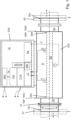
- Fig. 1 or 2 schematically show a measuring device or different, possibly also mutually complementary design variants of such a measuring device, which is particularly intended for measuring values for at least one measured variable - for example, namely a mass flow rate, a mass flow, a volume flow rate, a volume flow, density, viscosity or temperature - of a fluid medium being conveyed in a pipeline, for example a gas, liquid or dispersion.
- the measuring device comprises a measuring transducer 10 which is used to generate at least one measuring signal s1 (s1, s2) corresponding to the at least one measured variable, in particular having at least one signal parameter dependent on the measured variable and/or electrical, in particular vibronic or magnetic-inductive or acoustic, and a measuring device electronics 20 which is electrically connected to the measuring transducer and which is used to process the at least one measuring signal s1 (s1, s2).
- the measuring device electronics 20 can, as is quite usual with measuring devices of the type in question, also be housed in an electronics protective housing 2000 which is, for example, metallic and/or explosion-proof and/or sealed against splash water and/or dust.
- the measuring transducer 10 comprises at least one fluid line 200 - for example designed as a rigid and/or at least partially circular cylindrical tube - a first connection piece 100 - for example rotationally symmetrical with respect to an (imaginary) longitudinal axis - and a second connection piece 400 - for example identical in construction to the first connection piece and/or rotationally symmetrical with respect to an (imaginary) longitudinal axis.
- the fluid line 200 of the measuring transducer 10 has a lumen which is surrounded by a wall, for example made of a metal, such as a stainless steel, a titanium alloy, a tantalum alloy, a zirconium alloy, etc., and extends from a first flow opening located in a first line end of the fluid line 200 to a second flow opening located in a second line end of the same fluid line, and each of the two connecting pieces 100, 400 has a lumen which is surrounded by a wall made of a metal, for example a stainless steel, and extends from a first flow opening located in a respective first connection piece end 100+ or 400+ of the respective connecting piece 100, 400 - for example held by a (standardized) connection flange (101, 401) - to a second flow opening located in a second
- the lumen extends from the second flow opening located at the nozzle end 100# or 400# of the same connecting nozzle 100, 400 and is rotationally symmetrical, for example, with respect to an (imaginary)
- the fluid line 200 is connected both with its first line end 200+ to the second line end 100# of the first connection piece 100 and with its second line end 200# to the second line end 400# of the second connection piece 400, such that the lumen of the fluid line 200 communicates with both the lumen of the first connection piece 100 and the lumen of the second connection piece 200, forming a fluid channel extending continuously from the connection piece 100 to the connection piece 400, or that the first flow opening of the fluid line 200 extends into the second flow opening of the connection piece 100 and the second flow opening of the fluid line 200 open into the second flow opening of the second connection piece 400.
- connection piece 100 comprises at least one second fluid line 300, for example identical in construction to the fluid line 200, wherein in this case the at least two fluid lines 200, 300 can also be connected with their respective first line end 200+, 300+ to the second line end 100# of the connection piece 100 - then designed, for example, as a line branch - and with their respective second line end 200#, 300# to the second line end 400# of the connection piece 400 - then designed, for example, as a line union; this in particular in such a way that both the fluid line 200 with its first line end 200+ and the fluid line 300 with its first line end 300+ are each connected to the second line end 100# of the connection piece 100 and both the fluid line 200 with its second line end 200# and the fluid line 300 with its second line end 300# are each connected to the second line end 400# of the connection piece 400, or in such a way that both the lumen of the fluid line 200 and the lumen of the fluid line 300 communicate with the lumen of the connection piece 100 and/or in such a way that the first flow opening
- the measuring transducer can, if necessary, have further fluid lines connected to the connection pieces and housed within the protective housing 1000, for example as in the initially mentioned US-A 2010/0236338 or US-A 2017/0261474 shown in each case, four parallel and at least pairwise identical fluid lines or as in the above-mentioned US-A 2012/0279317 proposed eight or more fluid lines.
- the measuring device comprises at least one first sensor 1000, for example at least partially attached to the at least one fluid line 100 and/or at least placed in its vicinity.
- the measuring device electronics can also be electrically coupled to the sensor 51.
- the measuring transducer is designed as a measuring transducer of the vibration type, such that at least one of its fluid lines, in particular each of its fluid lines, is designed to be flowed through by the measuring medium and to be vibrated during this process; in the aforementioned case that two or more fluid lines are provided, for example, also simultaneously.
- the measuring transducer or the measuring device formed thereby further comprises at least one (electromechanical), for example electrodynamic or electromagnetic, vibration exciter 41.
- the vibration exciter 41 is electrically connected to the measuring device electronics and is also particularly designed to convert electrical power fed in by the measuring device electronics, for example by means of a corresponding electrical driver signal e1 of the measuring device electronics, into mechanical power causing mechanical vibrations of at least the fluid line 200; this for the aforementioned case that two fluid lines (200, 300) are provided, for example also in such a way that the two fluid lines (200, 300) carry out opposite (bending) vibrations.
- the sensor 51 can also be designed as a vibration sensor, for example an electrodynamic or opto-electrical one.
- the measuring device electronics 20 can also be electrically coupled to the sensor 52, for example in the same way as to the sensor 51, and can also be set up to process its measuring signal s2, in particular to determine measured values for the at least one measured variable by means of the first and second measuring signals s1, s2, for example to calculate measured values for the mass flow rate or the mass flow based on a phase difference established between the measuring signals.
- the measuring transducer 10 of the measuring device further comprises a (transducer) protective housing 1000 with a cavity surrounded by a wall, for example made of a metal, in particular a stainless steel, within which the at least one fluid line 200 or each of the fluid lines of the measuring transducer is placed.
- a first housing end 1000+ of the protective housing 1000 is formed by means of the connecting piece 100
- a second housing end 1000# of the protective housing 1000 is formed by means of the connecting piece 400, such that the protective housing 1000 has a side wall which at least partially laterally delimits the cavity described above, which is laterally connected both to the second line end 100# of the connecting piece 100 and to the second line end 400# of the connection piece 400 or is integrally connected thereto.
- the converter protective housing 1000 can also be mechanically firmly connected, for example, to the aforementioned electronic protective housing for the measuring system electronics to form a measuring device in a compact design, such that the electronic protective housing 2000 is held directly and/or only by the converter protective housing.
- the measuring transducer is particularly intended or designed to be integrated into a (piping) system comprising the aforementioned pipeline, for example in such a way that the nozzle end 100+ of the connecting nozzle 100 is fluidically connected, in particular leak-free, to a pipe end of a first pipeline segment of the pipeline system facing the measuring transducer 10 and/or that the nozzle end 400+ of the connecting nozzle 400 is fluidically connected, in particular leak-free, to a pipe end of a second pipeline segment of the pipeline system facing the measuring transducer, for example in such a way that a fluid channel extends continuously from the aforementioned first pipeline segment to the aforementioned second pipeline segment and/or in such a way that the measuring medium (during operation) is allowed to flow in a predetermined flow direction through the pipeline and the measuring transducer integrated therein.
- a fluid channel extends continuously from the aforementioned first pipeline segment to the aforementioned second pipeline segment and/or in such a way that the measuring medium (during operation) is allowed to flow in a predetermined flow
- the connecting nozzle 100 has a The metal compensator 110 is used in particular to set up the connecting piece 100 to react to a (tensile) force acting in the direction of its longitudinal axis in the area of the metal compensator 110 with a (longitudinal) expansion that is greater than a (longitudinal) expansion with
- the connecting piece 400 can also have a metal compensator 410, for example of the same construction as the metal compensator 110, in an area located between its first piece ends 400+ and its second piece ends 400# forming the second housing end 1000#.
- the second connection piece can also not have a metal compensator, for example in order to keep the pressure loss caused by the measuring transducer in the flowing medium as low as possible.
Landscapes
- Physics & Mathematics (AREA)
- Fluid Mechanics (AREA)
- General Physics & Mathematics (AREA)
- Electromagnetism (AREA)
- Measuring Volume Flow (AREA)
Claims (17)
- Appareil de mesure destiné à la mesure d'au moins une grandeur de mesure d'un produit fluide, notamment guidé dans une conduite, lequel appareil de mesure comprend :- un transducteur, notamment de type vibronique ou électromagnétique ou acoustique, lequel transducteur sert à générer au moins un signal de mesure (s1, s2) correspondant à l'au moins une grandeur de mesure ;- ainsi qu'une électronique d'appareil de mesure raccordée électriquement au transducteur et servant au traitement de l'au moins un signal de mesure (s1, s2) ;- le transducteur présentant-- un boîtier de protection (de transducteur) (1000),-- une première tubulure de raccordement (100), réalisée notamment sous la forme d'une dérivation de conduite et/ou à symétrie de rotation par rapport à un axe longitudinal (imaginaire), laquelle tubulure comprend un canal intérieur, notamment à symétrie de rotation par rapport à un axe longitudinal (imaginaire) de la première tubulure de raccordement, lequel canal est enveloppé par une paroi en métal et lequel canal s'étend d'une première ouverture d'écoulement située dans une première extrémité de tubulure (100+), notamment entourée d'une bride de raccordement, de la première tubulure de raccordement (100) jusqu'à une deuxième ouverture d'écoulement située dans une deuxième extrémité de tubulure (100#) de la même première tubulure de raccordement (100),-- une deuxième tubulure de raccordement (400), notamment de construction identique à la première tubulure de raccordement et/ou servant de jonction de conduite et/ou présentant une symétrie de rotation par rapport à un axe longitudinal (imaginaire), laquelle deuxième tubulure comprend un canal intérieur enveloppé par une paroi, notamment en métal, lequel canal s'étend d'une première ouverture d'écoulement située dans une première extrémité de tubulure (400+), notamment entourée d'une bride de raccordement, de la deuxième tubulure de raccordement (400) jusqu'à une deuxième ouverture d'écoulement située dans une deuxième extrémité de tubulure (400#) de la même deuxième tubulure de raccordement (400),-- ainsi qu'une première conduite de fluide (200), réalisée notamment sous la forme d'un tube rigide et/ou au moins partiellement cylindrique circulaire, laquelle conduite comprend un canal intérieur enveloppé par une paroi, notamment en un métal, lequel canal s'étend d'une première ouverture d'écoulement située dans une première extrémité de conduite (200+) de la première conduite de fluide jusqu'à une deuxième ouverture d'écoulement située dans une deuxième extrémité de conduite (200#) de ladite première conduite de fluide (200) ;- la première conduite de fluide (200) étant reliée aussi bien par sa première extrémité de conduite (200+) à la deuxième extrémité de conduite (100#) de la première tubulure de raccordement (100) que par sa deuxième extrémité de conduite (200#) à la deuxième extrémité de conduite (400#) de la deuxième tubulure de raccordement (400), notamment respectivement par liaison de matière, notamment de telle manière, que le canal intérieur de la première conduite de fluide (200) communique avec le canal intérieur de la première tubulure de raccordement (100) ainsi qu'avec le canal intérieur de la deuxième tubulure de raccordement (400) en formant un canal de fluide s'étendant de la première tubulure de raccordement à la deuxième tubulure de raccordement et/ou de telle sorte que la première ouverture d'écoulement de la première conduite de fluide (200) débouche dans la deuxième ouverture d'écoulement de la première tubulure de raccordement (100) et la deuxième ouverture d'écoulement de la première conduite de fluide (200) débouche dans la deuxième ouverture d'écoulement de la deuxième tubulure de raccordement (400) ;- le boîtier de protection (de transducteur) (1000) présentant une cavité enveloppée par une paroi, notamment en un métal, cavité à l'intérieur de laquelle est placée la première conduite de fluide (200) ;- et une première extrémité de boîtier (1000+) du boîtier de protection (1000) étant formée au moyen de la première tubulure de raccordement (100) et une deuxième extrémité de boîtier (1000#) du boîtier de protection (de transducteur) (1000) étant formée au moyen de la deuxième tubulure de raccordement (400), de telle manière que le boîtier de protection (1000) présente une paroi latérale délimitant latéralement au moins partiellement la cavité, laquelle paroi est fixée ou reliée à la fois à la deuxième extrémité de conduite (100#) de la première tubulure de raccordement (100) et à la deuxième extrémité de conduite (400#) de la deuxième tubulure de raccordement (400) ou laquelle paroi est respectivement reliée à celles-ci par une liaison de matière ;- caractérisé en ce qu'au moins la première tubulure de raccordement (100) présente - dans une zone située entre ses premières extrémités de tubulure (100+) et ses deuxièmes extrémités de tubulure (100#) formant la première extrémité de boîtier (1000+), notamment à savoir éloignée de sa première extrémité de tubulure et/ou de la première extrémité de boîtier - un compensateur métallique (110), notamment intégré et/ou conçu comme un compensateur axial.
- Appareil de mesure selon la revendication précédente,- pour lequel la première tubulure de raccordement est conçue pour réagir à une force (de traction) agissant dans la direction d'un axe longitudinal de la première tubulure de raccordement dans la zone du compensateur métallique avec un allongement (longitudinal) qui est supérieur à un allongement (longitudinal) avec lequel la tubulure de raccordement réagit dans la zone de la première extrémité de tubulure (100+) et/ou dans la zone de la deuxième extrémité de tubulure (100#) à la même force (de traction) ; et/ou- pour lequel la première tubulure de raccordement est conçue pour réagir - dans la zone du compensateur métallique, à une force (transversale) agissant transversalement à l'axe longitudinal et provoquant une flexion (par une force transversale), notamment droite, de la première tubulure de raccordement - avec une courbure qui est supérieure à une courbure avec laquelle la première tubulure de raccordement réagit, dans la zone de la première extrémité de tubulure (100+) et/ou dans la zone de la deuxième extrémité de tubulure (100#) à la même force (transversale).
- Appareil de mesure selon l'une des revendications précédentes, pour lequel le compensateur métallique présente au moins un renfoncement périphérique, notamment réalisé sous forme de moulure et/ou fermé sur lui-même, notamment le long d'une ligne périphérique circulaire et/ou fermé sur lui-même.
- Appareil de mesure selon l'une des revendications précédentes, pour lequel le compensateur métallique est formé par au moins un renfoncement périphérique, notamment réalisé sous forme de moulure et/ou fermé sur lui-même, notamment le long d'une ligne périphérique circulaire et/ou fermée sur lui-même, dans la paroi de la première tubulure de raccordement.
- Appareil de mesure selon l'une des revendications précédentes, pour lequel le compensateur métallique fait partie intégrante de la première tubulure de raccordement, notamment en ce que la paroi de la première tubulure de raccordement présente au moins un renfoncement périphérique, notamment réalisé sous forme de moulure et/ou fermé sur lui-même, notamment le long d'une ligne périphérique circulaire et/ou fermée sur lui.
- Appareil de mesure selon l'une des revendications précédentes,
pour lequel la paroi de la première tubulure de raccordement présente, pour former le compensateur métallique, au moins un renfoncement périphérique, notamment réalisé sous forme de moulure et/ou fermé sur lui-même, notamment le long d'une ligne périphérique circulaire et/ou fermé sur lui-même, et/ou pour lequel la paroi de la première tubulure de raccordement est réalisée par sections sous forme d'un soufflet métallique, notamment en ce que la paroi de la première tubulure de raccordement est ondulée au moins par sections et/ou en ce que la première tubulure de raccordement présente des diamètres intérieurs variant de manière ondulée dans la direction de l'axe longitudinal et des diamètres extérieurs variant de manière ondulée de la même manière. - Appareil de mesure selon la revendication précédente, pour lequel la paroi de la première tubulure de raccordement présente deux ou plusieurs renfoncements disposés les uns derrière les autres dans le sens de l'écoulement, lesquels renfoncements sont notamment de même forme.
- Appareil de mesure selon l'une des revendications précédentes, pour lequel le compensateur métallique de la première tubulure de raccordement est conçu comme un compensateur à tube ondulé.
- Appareil de mesure selon l'une des revendications précédentes, pour lequel le compensateur métallique de la première tubulure de raccordement est conçu comme un compensateur lentiforme.
- Appareil de mesure selon l'une des revendications précédentes, pour lequel le compensateur métallique de la première tubulure de raccordement est conçu comme un compensateur axial.
- Appareil de mesure selon l'une des revendications précédentes, pour lequel la deuxième tubulure de raccordement présente, dans une zone située entre ses premières extrémités de tubulure et ses deuxièmes extrémités de tubulure formant la première extrémité de boîtier, notamment à savoir éloignée de sa première extrémité de tubulure et/ou de la première extrémité de boîtier, un compensateur métallique (410), notamment intégré et/ou conçu comme compensateur axial, notamment de telle sorte que le compensateur métallique fait partie intégrante de la première tubulure de raccordement et/ou est de construction identique au compensateur métallique (110) de la première tubulure de raccordement (100).
- Appareil de mesure selon l'une des revendications 1 à 10, pour lequel la deuxième tubulure de raccordement ne comporte pas de compensateur métallique.
- Appareil de mesure selon l'une des revendications précédentes,- pour lequel le transducteur est conçu pour être intégré dans un système de conduite, notamment de telle sorte que la deuxième extrémité de la première tubulure de raccordement soit reliée fluidiquement à une extrémité, tournée vers le transducteur, d'un premier segment de conduite du système de conduite et/ou que la deuxième extrémité de la deuxième tubulure de raccordement soit reliée fluidiquement à une extrémité, tournée vers le transducteur, d'un deuxième segment de conduite du système de conduite, notamment en formant un canal de fluide s'étendant du premier segment de conduite au deuxième segment de conduite et/ou exempt de fuites ; et/ou- la première et la deuxième tubulure de raccordement (100, 400) étant alignées l'une avec l'autre, notamment de telle sorte qu'un prolongement d'un axe longitudinal de la première tubulure de raccordement est parallèle à un prolongement d'un axe longitudinal de la deuxième tubulure de raccordement ou coïncide avec celui-ci.
- Appareil de mesure selon l'une des revendications précédentes,- pour lequel la première conduite de fluide (200) est conçue pour être traversée par le produit et pour être mise en vibrations pendant ce temps ; et/ou- pour lequel l'électronique d'appareil de mesure est conçue pour alimenter un signal d'attaque électrique dans le transducteur ; et/ou- pour lequel la première conduite de fluide (200) est courbée au moins par sections, notamment en forme de V et/ou en forme de U et/ou en forme d'arc de cercle ; et/ou- pour lequel la première conduite de fluide (200) est droite au moins par sections, notamment cylindrique creuse.
- Appareil de mesure selon l'une des revendications précédentes, comprenant en outre :- au moins une deuxième conduite de fluide (300), réalisée notamment sous forme de tube rigide et/ou cylindrique circulaire au moins par sections et/ou de construction identique à la première conduite de fluide, avec un canal intérieur enveloppé par une paroi, notamment en un métal, lequel canal s'étend d'une première ouverture d'écoulement située dans une première extrémité de conduite (300+) de la deuxième conduite de fluide jusqu'à une deuxième ouverture d'écoulement située dans une deuxième extrémité de conduite (300#) de ladite deuxième conduite de fluide (300),- la deuxième conduite de fluide (300) étant reliée par sa première extrémité de conduite à la deuxième extrémité de conduite (100#) de la première tubulure de raccordement (100) et par sa deuxième extrémité de conduite à la deuxième extrémité de conduite (400#) de la deuxième tubulure de raccordement (400), notamment de telle manière qu'aussi bien le canal intérieur de la première conduite de fluide (200) que le canal intérieur de la deuxième conduite de fluide (300) communiquent aussi bien avec le canal intérieur de la première tubulure de raccordement (100) qu'avec le canal intérieur de la deuxième tubulure de raccordement (400) et/ou de telle manière que la première ouverture d'écoulement de la deuxième conduite de fluide (300) débouche dans une troisième ouverture d'écoulement de la première tubulure de raccordement (100), laquelle troisième ouverture est également située dans la deuxième extrémité de la première tubulure de raccordement, et que la deuxième ouverture d'écoulement de la deuxième conduite de fluide (300) débouche dans une troisième ouverture d'écoulement de la deuxième tubulure de raccordement (400), laquelle troisième ouverture est également située dans la deuxième extrémité de la deuxième tubulure de raccordement.
- Appareil de mesure selon l'une des revendications précédentes,- comprenant en outre : au moins un excitateur de vibrations (41), notamment électromécanique ou électrodynamique, destiné à générer ou maintenir des vibrations mécaniques, notamment des vibrations de flexion, au moins de la première conduite de fluide (200), notamment à générer ou maintenir des vibrations mécaniques aussi bien de la première conduite de fluide (200) que de la deuxième conduite de fluide (300) ; et/ou- comprenant en outre : au moins un premier capteur (51), notamment monté au moins sur la première conduite de fluide et/ou placé au moins à proximité de ladite conduite, lequel capteur est destiné à générer au moins un paramètre de signal (s1) - notamment électrique - correspondant à une grandeur de mesure d'un fluide guidé dans le système de conduite de fluide, à savoir au moins un paramètre de signal dépendant de ladite grandeur de mesure, notamment un niveau de signal dépendant de ladite grandeur de mesure et/ou une fréquence de signal dépendant de ladite grandeur de mesure et/ou un angle de phase dépendant de ladite grandeur de mesure.
- Utilisation d'un appareil de mesure selon l'une des revendications précédentes, lequel appareil est destiné à déterminer des valeurs mesurées pour au moins une grandeur de mesure - notamment à savoir un débit massique, un débit volumique, un débit volumétrique, une densité, une viscosité ou une température - d'un produit fluide guidé dans une conduite, notamment d'un gaz, d'un liquide ou d'une dispersion, notamment de telle sorte que la première tubulure de raccordement est disposée côté entrée en ce qui concerne un sens d'écoulement du produit mis en écoulement à travers le transducteur et/ou que le produit est mis en écoulement dans un sens d'écoulement prédéfini à travers la conduite ainsi qu'à travers le transducteur intégré dans la même conduite.
Applications Claiming Priority (2)
| Application Number | Priority Date | Filing Date | Title |
|---|---|---|---|
| DE102021104631.9A DE102021104631A1 (de) | 2021-02-26 | 2021-02-26 | Meßgerät |
| PCT/EP2022/051855 WO2022179791A1 (fr) | 2021-02-26 | 2022-01-27 | Dispositif de mesure |
Publications (2)
| Publication Number | Publication Date |
|---|---|
| EP4298408A1 EP4298408A1 (fr) | 2024-01-03 |
| EP4298408B1 true EP4298408B1 (fr) | 2025-03-05 |
Family
ID=80168061
Family Applications (1)
| Application Number | Title | Priority Date | Filing Date |
|---|---|---|---|
| EP22702248.0A Active EP4298408B1 (fr) | 2021-02-26 | 2022-01-27 | Dispositif de mesure |
Country Status (5)
| Country | Link |
|---|---|
| US (1) | US20240142286A1 (fr) |
| EP (1) | EP4298408B1 (fr) |
| CN (1) | CN116997775A (fr) |
| DE (1) | DE102021104631A1 (fr) |
| WO (1) | WO2022179791A1 (fr) |
Families Citing this family (1)
| Publication number | Priority date | Publication date | Assignee | Title |
|---|---|---|---|---|
| WO2021177967A1 (fr) * | 2020-03-05 | 2021-09-10 | Micro Motion, Inc. | Système de raccordement de débitmètre |
Family Cites Families (33)
| Publication number | Priority date | Publication date | Assignee | Title |
|---|---|---|---|---|
| NL8500112A (nl) | 1985-01-17 | 1986-08-18 | Techno Diagnosis Bv | Brandstofstroommeter en brandstoftoevoersysteem. |
| US4655089A (en) | 1985-06-07 | 1987-04-07 | Smith Meter Inc. | Mass flow meter and signal processing system |
| GB2192714A (en) * | 1986-07-16 | 1988-01-20 | Schlumberger Electronics | Coriolis mass flow meter |
| DE4027936A1 (de) | 1990-09-04 | 1992-03-05 | Rota Yokogawa Gmbh & Co Kg | Massedosierautomat |
| EP0518124B1 (fr) | 1991-06-09 | 1995-09-06 | Krohne AG | Débitmètre massique Coriolis |
| WO1996008697A2 (fr) | 1994-09-08 | 1996-03-21 | Smith Meter Inc. | Debitmetre massique et ensemble de conduits |
| DE69533747T2 (de) * | 1995-08-21 | 2005-03-17 | Oval Corp. | Coriolisdurchflussmesser |
| US5850039A (en) | 1997-02-27 | 1998-12-15 | Micro Motion | Coriolis flowmeter having axially compliant case ends |
| US6343517B1 (en) * | 1999-06-30 | 2002-02-05 | Micro Motion, Inc. | Apparatus for connecting a coriolis flowmeter flow tube to a flowmeter case |
| DE10003784B4 (de) * | 1999-12-27 | 2004-12-09 | Krohne Ag | Coriolis-Massendurchflußmeßgerät |
| HU225071B1 (en) | 2000-12-21 | 2006-06-28 | Sandor Kun | Combined mass flow meter device and method for measuring mass flow of a non solid medium |
| DE10137921A1 (de) * | 2001-08-02 | 2003-02-13 | Abb Research Ltd | Verfahren und Vorrichtung zum Bestimmen des Massendurchflusses |
| EP1296119A1 (fr) | 2001-09-21 | 2003-03-26 | Endress + Hauser Flowtec AG | Capteur de mesure du type vibrant |
| DE102005042677A1 (de) * | 2005-08-27 | 2007-03-08 | Abb Patent Gmbh | Coriolis-Massendurchfluss-Aufnehmer |
| EP2118623B1 (fr) * | 2006-12-22 | 2016-11-09 | Endress+Hauser Flowtec AG | Transducteur de mesure du type à vibrations |
| US8327719B2 (en) | 2009-03-11 | 2012-12-11 | Endress + Hauser Flowtec Ag | Measuring transducer of vibration-type, as well as an in-line measuring device having such a measuring transducer |
| DE102009012474A1 (de) | 2009-03-12 | 2010-09-16 | Endress + Hauser Flowtec Ag | Meßsystem mit einem Messwandler vom Vibrationstyp |
| EP2516971B1 (fr) | 2009-12-21 | 2020-03-04 | Endress+Hauser Flowtec AG | Capteur de mesure du type à vibration et système de mesure le comprenant |
| CN103052868A (zh) * | 2010-08-02 | 2013-04-17 | 西门子公司 | 科里奥利质量流量计和运行科里奥利质量流量计的方法 |
| US8931346B2 (en) * | 2010-12-30 | 2015-01-13 | Endress + Hauser Flowtec Ag | Vibration type measuring transducer and measuring system formed therewith |
| CN103620351B (zh) | 2011-05-02 | 2017-01-25 | 恩德斯+豪斯流量技术股份有限公司 | 振动型测量换能器以及其所形成的测量系统 |
| SG11201403799WA (en) * | 2012-01-03 | 2014-08-28 | Micro Motion Inc | Method and apparatus for retaining a flange on a fluid meter |
| JP6279109B2 (ja) * | 2014-07-01 | 2018-02-14 | マイクロ モーション インコーポレイテッド | 流体モメンタム検出方法及び関連装置 |
| DE102015103208A1 (de) | 2014-10-17 | 2016-04-21 | Endress + Hauser Flowtec Ag | Meßsystem zum Messen wenigstens einer Meßgröße eines Fluids sowie Verfahren zum Betreiben eines solchen Meßsystems |
| DE102014118367A1 (de) | 2014-12-10 | 2016-06-16 | Endress+Hauser Flowtec Ag | Meßaufnehmer vom Vibrationstyp sowie damit gebildetes Meßsystem |
| DE102015104931A1 (de) | 2014-12-31 | 2016-06-30 | Endress + Hauser Flowtec Ag | Coriolis-Massedurchfussmessgerät mit vier gebogenen Messrohren |
| DE102015220629A1 (de) | 2015-10-22 | 2017-04-27 | Bayerische Motoren Werke Aktiengesellschaft | Verbindungselement, Baugruppe mit einem Verbindungselement und Verfahren zur Verbindung zweier Komponenten |
| DE102016109058A1 (de) * | 2016-05-17 | 2017-11-23 | Endress+Hauser Flowtec Ag | Fluidleitungssystem |
| DE102016118016B4 (de) | 2016-09-23 | 2021-07-15 | Krohne Ag | Coriolis-Massedurchflussmessgerät mit aktiven und passiven Messrohren |
| WO2018121930A1 (fr) * | 2016-12-29 | 2018-07-05 | Endress+Hauser Flowtec Ag | Système de mesure vibronique pour la mesure d'un débit massique |
| DE102017012058A1 (de) * | 2017-12-28 | 2019-07-04 | Endress+Hauser Flowtec Ag | Messgerät vom Vibraationstyp mit einem Messrohr |
| DE102018133318A1 (de) | 2018-12-21 | 2020-06-25 | Endress+Hauser Flowtec Ag | Vibronisches Meßsystem |
| DE102019114330A1 (de) | 2019-05-28 | 2020-12-03 | Endress+Hauser Flowtec Ag | Meßwandler vom Vibrationstyp sowie damit gebildetes vibronisches Meßsystem |
-
2021
- 2021-02-26 DE DE102021104631.9A patent/DE102021104631A1/de active Pending
-
2022
- 2022-01-27 EP EP22702248.0A patent/EP4298408B1/fr active Active
- 2022-01-27 US US18/547,798 patent/US20240142286A1/en active Pending
- 2022-01-27 WO PCT/EP2022/051855 patent/WO2022179791A1/fr not_active Ceased
- 2022-01-27 CN CN202280016936.6A patent/CN116997775A/zh active Pending
Also Published As
| Publication number | Publication date |
|---|---|
| EP4298408A1 (fr) | 2024-01-03 |
| DE102021104631A1 (de) | 2022-09-01 |
| WO2022179791A1 (fr) | 2022-09-01 |
| CN116997775A (zh) | 2023-11-03 |
| US20240142286A1 (en) | 2024-05-02 |
Similar Documents
| Publication | Publication Date | Title |
|---|---|---|
| EP2612114B1 (fr) | Système de mesure comprenant un capteur de mesure de type vibratoire | |
| EP3189311B1 (fr) | Module de capteur, capteur et système de mesure correspondant | |
| EP2406590B1 (fr) | Capteur de mesure à vibration et instrument de mesure en ligne muni d'un tel capteur de mesure | |
| EP3427013B1 (fr) | Groupe d'assemblage pour un capteur, capteur et système de mesure construit avec celui-ci | |
| EP2350577B1 (fr) | Dispositif à aimant et capteur de mesure de type à vibrations le comprenant | |
| EP1996902B1 (fr) | Enregistreur de mesure du type a vibrations | |
| EP2304393B1 (fr) | Transducteur de mesure du type à vibration | |
| EP3353503B1 (fr) | Système de mesure et utilisation d'un système de mesure | |
| WO2012150241A2 (fr) | Capteur de mesure de type vibratoire et système de mesure formé avec ce capteur de mesure | |
| EP1248084B1 (fr) | Capteur de débit massique selon Coriolis avec deux tubes courbés | |
| EP3230696A1 (fr) | Débitmètre à ultrasons | |
| EP3922972A2 (fr) | Dispositif de mesure de la pression d'un fluide circulant dans une tuyauterie | |
| EP1797404B1 (fr) | Systeme composite, procede de fabrication associe et capteur de mesure dote d'un systeme composite de ce type | |
| EP4298408B1 (fr) | Dispositif de mesure | |
| EP1914526B1 (fr) | Capteur de mesure du type de vibration | |
| WO2023165901A1 (fr) | Capteur et système de mesure formé avec celui-ci | |
| DE102020134264A1 (de) | Sensor zum Erfassen von Druckschwankungen in einem strömenden Fluid sowie damit gebildetes Meßsystem | |
| EP1664689B1 (fr) | Procede pour regler la frequence propre mecanique d'un corps creux | |
| WO2025141009A1 (fr) | Diviseur d'écoulement et système de conduite de fluide formé avec celui-ci | |
| DE102016110905A1 (de) | Messeinrichtung zur Messung einer Messgröße eines strömenden Fluids | |
| DE102005013649A1 (de) | Meßaufnehmer vom Vibrationstyp |
Legal Events
| Date | Code | Title | Description |
|---|---|---|---|
| STAA | Information on the status of an ep patent application or granted ep patent |
Free format text: STATUS: UNKNOWN |
|
| STAA | Information on the status of an ep patent application or granted ep patent |
Free format text: STATUS: THE INTERNATIONAL PUBLICATION HAS BEEN MADE |
|
| PUAI | Public reference made under article 153(3) epc to a published international application that has entered the european phase |
Free format text: ORIGINAL CODE: 0009012 |
|
| STAA | Information on the status of an ep patent application or granted ep patent |
Free format text: STATUS: REQUEST FOR EXAMINATION WAS MADE |
|
| 17P | Request for examination filed |
Effective date: 20230724 |
|
| AK | Designated contracting states |
Kind code of ref document: A1 Designated state(s): AL AT BE BG CH CY CZ DE DK EE ES FI FR GB GR HR HU IE IS IT LI LT LU LV MC MK MT NL NO PL PT RO RS SE SI SK SM TR |
|
| DAV | Request for validation of the european patent (deleted) | ||
| DAX | Request for extension of the european patent (deleted) | ||
| RAP3 | Party data changed (applicant data changed or rights of an application transferred) |
Owner name: ENDRESS+HAUSER FLOWTEC AG |
|
| GRAP | Despatch of communication of intention to grant a patent |
Free format text: ORIGINAL CODE: EPIDOSNIGR1 |
|
| STAA | Information on the status of an ep patent application or granted ep patent |
Free format text: STATUS: GRANT OF PATENT IS INTENDED |
|
| INTG | Intention to grant announced |
Effective date: 20241122 |
|
| GRAS | Grant fee paid |
Free format text: ORIGINAL CODE: EPIDOSNIGR3 |
|
| GRAA | (expected) grant |
Free format text: ORIGINAL CODE: 0009210 |
|
| STAA | Information on the status of an ep patent application or granted ep patent |
Free format text: STATUS: THE PATENT HAS BEEN GRANTED |
|
| AK | Designated contracting states |
Kind code of ref document: B1 Designated state(s): AL AT BE BG CH CY CZ DE DK EE ES FI FR GB GR HR HU IE IS IT LI LT LU LV MC MK MT NL NO PL PT RO RS SE SI SK SM TR |
|
| REG | Reference to a national code |
Ref country code: GB Ref legal event code: FG4D Free format text: NOT ENGLISH |
|
| REG | Reference to a national code |
Ref country code: CH Ref legal event code: EP |
|
| REG | Reference to a national code |
Ref country code: IE Ref legal event code: FG4D Free format text: LANGUAGE OF EP DOCUMENT: GERMAN |
|
| REG | Reference to a national code |
Ref country code: DE Ref legal event code: R096 Ref document number: 502022003099 Country of ref document: DE |
|
| P01 | Opt-out of the competence of the unified patent court (upc) registered |
Free format text: CASE NUMBER: APP_14084/2025 Effective date: 20250321 |
|
| REG | Reference to a national code |
Ref country code: NL Ref legal event code: FP |
|
| PG25 | Lapsed in a contracting state [announced via postgrant information from national office to epo] |
Ref country code: RS Free format text: LAPSE BECAUSE OF FAILURE TO SUBMIT A TRANSLATION OF THE DESCRIPTION OR TO PAY THE FEE WITHIN THE PRESCRIBED TIME-LIMIT Effective date: 20250605 |
|
| PG25 | Lapsed in a contracting state [announced via postgrant information from national office to epo] |
Ref country code: FI Free format text: LAPSE BECAUSE OF FAILURE TO SUBMIT A TRANSLATION OF THE DESCRIPTION OR TO PAY THE FEE WITHIN THE PRESCRIBED TIME-LIMIT Effective date: 20250305 |
|
| PG25 | Lapsed in a contracting state [announced via postgrant information from national office to epo] |
Ref country code: ES Free format text: LAPSE BECAUSE OF FAILURE TO SUBMIT A TRANSLATION OF THE DESCRIPTION OR TO PAY THE FEE WITHIN THE PRESCRIBED TIME-LIMIT Effective date: 20250305 |
|
| REG | Reference to a national code |
Ref country code: LT Ref legal event code: MG9D |
|
| PG25 | Lapsed in a contracting state [announced via postgrant information from national office to epo] |
Ref country code: NO Free format text: LAPSE BECAUSE OF FAILURE TO SUBMIT A TRANSLATION OF THE DESCRIPTION OR TO PAY THE FEE WITHIN THE PRESCRIBED TIME-LIMIT Effective date: 20250605 |
|
| PG25 | Lapsed in a contracting state [announced via postgrant information from national office to epo] |
Ref country code: HR Free format text: LAPSE BECAUSE OF FAILURE TO SUBMIT A TRANSLATION OF THE DESCRIPTION OR TO PAY THE FEE WITHIN THE PRESCRIBED TIME-LIMIT Effective date: 20250305 |
|
| PG25 | Lapsed in a contracting state [announced via postgrant information from national office to epo] |
Ref country code: LV Free format text: LAPSE BECAUSE OF FAILURE TO SUBMIT A TRANSLATION OF THE DESCRIPTION OR TO PAY THE FEE WITHIN THE PRESCRIBED TIME-LIMIT Effective date: 20250305 |
|
| PG25 | Lapsed in a contracting state [announced via postgrant information from national office to epo] |
Ref country code: GR Free format text: LAPSE BECAUSE OF FAILURE TO SUBMIT A TRANSLATION OF THE DESCRIPTION OR TO PAY THE FEE WITHIN THE PRESCRIBED TIME-LIMIT Effective date: 20250606 Ref country code: BG Free format text: LAPSE BECAUSE OF FAILURE TO SUBMIT A TRANSLATION OF THE DESCRIPTION OR TO PAY THE FEE WITHIN THE PRESCRIBED TIME-LIMIT Effective date: 20250305 |
|
| PG25 | Lapsed in a contracting state [announced via postgrant information from national office to epo] |
Ref country code: SE Free format text: LAPSE BECAUSE OF FAILURE TO SUBMIT A TRANSLATION OF THE DESCRIPTION OR TO PAY THE FEE WITHIN THE PRESCRIBED TIME-LIMIT Effective date: 20250305 |
|
| PG25 | Lapsed in a contracting state [announced via postgrant information from national office to epo] |
Ref country code: SM Free format text: LAPSE BECAUSE OF FAILURE TO SUBMIT A TRANSLATION OF THE DESCRIPTION OR TO PAY THE FEE WITHIN THE PRESCRIBED TIME-LIMIT Effective date: 20250305 |
|
| PG25 | Lapsed in a contracting state [announced via postgrant information from national office to epo] |
Ref country code: PT Free format text: LAPSE BECAUSE OF FAILURE TO SUBMIT A TRANSLATION OF THE DESCRIPTION OR TO PAY THE FEE WITHIN THE PRESCRIBED TIME-LIMIT Effective date: 20250707 |
|
| PG25 | Lapsed in a contracting state [announced via postgrant information from national office to epo] |
Ref country code: IT Free format text: LAPSE BECAUSE OF FAILURE TO SUBMIT A TRANSLATION OF THE DESCRIPTION OR TO PAY THE FEE WITHIN THE PRESCRIBED TIME-LIMIT Effective date: 20250305 Ref country code: PL Free format text: LAPSE BECAUSE OF FAILURE TO SUBMIT A TRANSLATION OF THE DESCRIPTION OR TO PAY THE FEE WITHIN THE PRESCRIBED TIME-LIMIT Effective date: 20250305 |
|
| PG25 | Lapsed in a contracting state [announced via postgrant information from national office to epo] |
Ref country code: EE Free format text: LAPSE BECAUSE OF FAILURE TO SUBMIT A TRANSLATION OF THE DESCRIPTION OR TO PAY THE FEE WITHIN THE PRESCRIBED TIME-LIMIT Effective date: 20250305 Ref country code: CZ Free format text: LAPSE BECAUSE OF FAILURE TO SUBMIT A TRANSLATION OF THE DESCRIPTION OR TO PAY THE FEE WITHIN THE PRESCRIBED TIME-LIMIT Effective date: 20250305 |
|
| PG25 | Lapsed in a contracting state [announced via postgrant information from national office to epo] |
Ref country code: RO Free format text: LAPSE BECAUSE OF FAILURE TO SUBMIT A TRANSLATION OF THE DESCRIPTION OR TO PAY THE FEE WITHIN THE PRESCRIBED TIME-LIMIT Effective date: 20250305 |
|
| PG25 | Lapsed in a contracting state [announced via postgrant information from national office to epo] |
Ref country code: SK Free format text: LAPSE BECAUSE OF FAILURE TO SUBMIT A TRANSLATION OF THE DESCRIPTION OR TO PAY THE FEE WITHIN THE PRESCRIBED TIME-LIMIT Effective date: 20250305 |
|
| PG25 | Lapsed in a contracting state [announced via postgrant information from national office to epo] |
Ref country code: IS Free format text: LAPSE BECAUSE OF FAILURE TO SUBMIT A TRANSLATION OF THE DESCRIPTION OR TO PAY THE FEE WITHIN THE PRESCRIBED TIME-LIMIT Effective date: 20250705 |
|
| REG | Reference to a national code |
Ref country code: DE Ref legal event code: R097 Ref document number: 502022003099 Country of ref document: DE |
|
| PLBE | No opposition filed within time limit |
Free format text: ORIGINAL CODE: 0009261 |
|
| STAA | Information on the status of an ep patent application or granted ep patent |
Free format text: STATUS: NO OPPOSITION FILED WITHIN TIME LIMIT |
|
| PG25 | Lapsed in a contracting state [announced via postgrant information from national office to epo] |
Ref country code: DK Free format text: LAPSE BECAUSE OF FAILURE TO SUBMIT A TRANSLATION OF THE DESCRIPTION OR TO PAY THE FEE WITHIN THE PRESCRIBED TIME-LIMIT Effective date: 20250305 |
|
| REG | Reference to a national code |
Ref country code: CH Ref legal event code: L10 Free format text: ST27 STATUS EVENT CODE: U-0-0-L10-L00 (AS PROVIDED BY THE NATIONAL OFFICE) Effective date: 20260114 |
|
| 26N | No opposition filed |
Effective date: 20251208 |
|
| PGFP | Annual fee paid to national office [announced via postgrant information from national office to epo] |
Ref country code: NL Payment date: 20260121 Year of fee payment: 5 |
|
| PGFP | Annual fee paid to national office [announced via postgrant information from national office to epo] |
Ref country code: GB Payment date: 20260123 Year of fee payment: 5 |
|
| PGFP | Annual fee paid to national office [announced via postgrant information from national office to epo] |
Ref country code: DE Payment date: 20260121 Year of fee payment: 5 |
|
| PGFP | Annual fee paid to national office [announced via postgrant information from national office to epo] |
Ref country code: AT Payment date: 20260301 Year of fee payment: 5 |
|
| PGFP | Annual fee paid to national office [announced via postgrant information from national office to epo] |
Ref country code: FR Payment date: 20260123 Year of fee payment: 5 |