EP4298410B1 - Dispositif de pesée et procédé de pesée avec une correction centrale de la valeur de mesure - Google Patents
Dispositif de pesée et procédé de pesée avec une correction centrale de la valeur de mesure Download PDFInfo
- Publication number
- EP4298410B1 EP4298410B1 EP22707431.7A EP22707431A EP4298410B1 EP 4298410 B1 EP4298410 B1 EP 4298410B1 EP 22707431 A EP22707431 A EP 22707431A EP 4298410 B1 EP4298410 B1 EP 4298410B1
- Authority
- EP
- European Patent Office
- Prior art keywords
- weighing device
- signal
- weighing
- error
- weight
- Prior art date
- Legal status (The legal status is an assumption and is not a legal conclusion. Google has not performed a legal analysis and makes no representation as to the accuracy of the status listed.)
- Active
Links
Images



Classifications
-
- G—PHYSICS
- G01—MEASURING; TESTING
- G01G—WEIGHING
- G01G3/00—Weighing apparatus characterised by the use of elastically-deformable members, e.g. spring balances
- G01G3/12—Weighing apparatus characterised by the use of elastically-deformable members, e.g. spring balances wherein the weighing element is in the form of a solid body stressed by pressure or tension during weighing
- G01G3/14—Weighing apparatus characterised by the use of elastically-deformable members, e.g. spring balances wherein the weighing element is in the form of a solid body stressed by pressure or tension during weighing measuring variations of electrical resistance
- G01G3/1414—Arrangements for correcting or for compensating for unwanted effects
-
- G—PHYSICS
- G01—MEASURING; TESTING
- G01G—WEIGHING
- G01G3/00—Weighing apparatus characterised by the use of elastically-deformable members, e.g. spring balances
- G01G3/12—Weighing apparatus characterised by the use of elastically-deformable members, e.g. spring balances wherein the weighing element is in the form of a solid body stressed by pressure or tension during weighing
- G01G3/14—Weighing apparatus characterised by the use of elastically-deformable members, e.g. spring balances wherein the weighing element is in the form of a solid body stressed by pressure or tension during weighing measuring variations of electrical resistance
- G01G3/1414—Arrangements for correcting or for compensating for unwanted effects
- G01G3/1416—Arrangements for correcting or for compensating for unwanted effects for non-linearity
-
- G—PHYSICS
- G01—MEASURING; TESTING
- G01G—WEIGHING
- G01G23/00—Auxiliary devices for weighing apparatus
- G01G23/01—Testing or calibrating of weighing apparatus
-
- G—PHYSICS
- G01—MEASURING; TESTING
- G01G—WEIGHING
- G01G23/00—Auxiliary devices for weighing apparatus
- G01G23/06—Means for damping oscillations, e.g. of weigh beams
-
- G—PHYSICS
- G01—MEASURING; TESTING
- G01G—WEIGHING
- G01G23/00—Auxiliary devices for weighing apparatus
- G01G23/18—Indicating devices, e.g. for remote indication; Recording devices; Scales, e.g. graduated
- G01G23/36—Indicating the weight by electrical means, e.g. using photoelectric cells
- G01G23/37—Indicating the weight by electrical means, e.g. using photoelectric cells involving digital counting
-
- G—PHYSICS
- G01—MEASURING; TESTING
- G01G—WEIGHING
- G01G3/00—Weighing apparatus characterised by the use of elastically-deformable members, e.g. spring balances
- G01G3/12—Weighing apparatus characterised by the use of elastically-deformable members, e.g. spring balances wherein the weighing element is in the form of a solid body stressed by pressure or tension during weighing
- G01G3/14—Weighing apparatus characterised by the use of elastically-deformable members, e.g. spring balances wherein the weighing element is in the form of a solid body stressed by pressure or tension during weighing measuring variations of electrical resistance
- G01G3/1414—Arrangements for correcting or for compensating for unwanted effects
- G01G3/1418—Arrangements for correcting or for compensating for unwanted effects for temperature variations
-
- G—PHYSICS
- G01—MEASURING; TESTING
- G01G—WEIGHING
- G01G3/00—Weighing apparatus characterised by the use of elastically-deformable members, e.g. spring balances
- G01G3/12—Weighing apparatus characterised by the use of elastically-deformable members, e.g. spring balances wherein the weighing element is in the form of a solid body stressed by pressure or tension during weighing
- G01G3/14—Weighing apparatus characterised by the use of elastically-deformable members, e.g. spring balances wherein the weighing element is in the form of a solid body stressed by pressure or tension during weighing measuring variations of electrical resistance
- G01G3/142—Circuits specially adapted therefor
- G01G3/147—Circuits specially adapted therefor involving digital counting
-
- G—PHYSICS
- G01—MEASURING; TESTING
- G01G—WEIGHING
- G01G3/00—Weighing apparatus characterised by the use of elastically-deformable members, e.g. spring balances
- G01G3/18—Temperature-compensating arrangements
Definitions
- the present invention relates to a weighing device and a weighing method with a central digital measured value correction.
- Weighing devices are used to measure forces, especially the weight of goods being weighed.
- Weighing devices usually have a force sensor, a load cell and an evaluation device.
- the force absorption is a structural element or a body onto which the weighing object can be placed, so that the force absorption absorbs the weight of the weighing object and transfers it to a base.
- the load cell comprises one or more force sensors and is used to detect the weight absorbed by the force absorption.
- Industrial weighing devices can also comprise several load cells. The load cells are arranged in the force path from the force absorption to the base, i.e. they record all or part of the weight that is transferred to the base via the load cell(s).
- the load cells can detect changes in the shape of a measuring body that is connected to the force sensor or is part of the force sensor, for example by means of strain gauges.
- the strain gauges can, for example, be attached to a support of the force sensor and detect the deformation of the support, from which the applied weight force can be determined. Shear forces that are proportional to the weight force can also be measured on horizontal beams in this way. There are therefore a wide variety of ways in which the load cells can be arranged in the weighing device.
- each load cell is assigned an evaluation device with which the weight force measured by the load cell is determined. If a weighing device has several load cells, the corresponding weight forces are added together.
- a load cell is produced in which a modular correction device is integrated.
- This load cell can also have a temperature sensor in order to take the measured temperature into account when correcting the measurement signals.
- a weighing device with an integrated correction function is created. This weighing device has different characteristics for different temperatures and different load directions. This corrects temperature and hysteresis effects.
- a method for exchanging load cells in a calibrated weighing arrangement with several load cells is described.
- the load cells are connected to a control unit via at least one BUS system.
- the load cells transmit the weight values to be measured in the form of voltages, which produce corresponding counter values in the control unit.
- Each load cell has a set of internal parameters per load cell. When the load cells are exchanged, the written data of internal parameters of the new load cell in the weighing arrangement are made available for reading in the internal parameter memory of the load cells.
- the EP 2 278 283 A1 discloses a method for temperature correction of a force measuring device, in particular a scale.
- the force sensors or load cells are rigidly connected to the force sensor, usually screwed or glued.
- the invention is based on the object of providing a weighing device and a weighing method which make it possible to carry out force measurements with high accuracy, whereby the weighing device used here should be designed to be very simple, cost-effective and reliable.
- This object is achieved by the subject matter of the independent patent claims.
- Advantageous embodiments are specified in the respective subclaims.
- a weighing device with a central digital measurement value correction which comprises at least one load cell which is connected via a signal and/or data line to a central evaluation device for transmitting a weight measurement signal, wherein the central evaluation device has an evaluation unit for determining the force measured with the weighing device based on the weight measurement signal.
- the weighing device is characterized in that the evaluation unit comprises a digital functional model of the weighing device, which has one or more error simulation modules, wherein each error simulation module represents a model of the weighing device that simulates a specific measurement error of the weighing device, and each error simulation module has one or more model parameters with which the weighing device is modeled, and a learning device is provided with which the model parameters can be determined during a learning process in which reference measurement signals are generated by means of one or more reference loads, wherein the functional model has a characteristic module which converts the weight measurement signal into a weight signal or vice versa and the characteristic module has characteristic parameters which are determined by means of the learning device during the learning process.
- an error simulation module changes a signal. This change can be carried out in such a way that a predetermined error is added to the signal. However, this change can also be a change to the signal in such a way that the signal is cleaned up or corrected for a predetermined error.
- the central digital measurement value correction using a digital functional model that is taught using a learning process allows the use of a single or multiple simple load cells that are integrated into the weighing device.
- the characteristic curve of the entire weighing device using the characteristic curve module and teaching one or more error simulation modules, the calibration of a single load cell for the entire weighing device is negligible; instead, the characteristic curve and/or the error simulation modules are taught for the entire weighing device at once or one after the other using the functional model.
- the mechanical structure of the weighing device with a force sensor and one or more load cells can therefore initially be set up according to the local conditions.
- the load cells are connected to the central evaluation device via a signal and/or data line and then the characteristic curve parameters of the characteristic curve module and the model parameters of the one or more error simulation modules are taught.
- the functional model thus represents the entire weighing device.
- the characteristic curve module is designed to convert the weight signal into a (virtual) weight measurement signal and the error simulation modules are designed to change this weight measurement signal by an error component.
- the weight signal is an analog or digital signal that represents the weight to be measured.
- the weight measurement signal is a signal that corresponds to the measurement signal generated by the load cells. When using a single strain gauge, the weight measurement signal corresponds to the strain of the strain gauge.
- the input value is the weight signal and the output value is a simulated error-prone weight measurement signal.
- the output value is a simulated error-prone weight measurement signal.
- the characteristic curve module to convert an error-prone weight measurement signal into an error-prone weight value and for the error simulation module(s) to convert the error-prone weight signal or the error-prone weight value into a corrected weight value.
- the input variable is the error-prone, actually measured weight measurement signal and the output variable is the corrected weight value.
- These error simulation modules can also be referred to as correction modules, as they correct the weight value by the respective error.
- modeling the inverted functional model is much more complex than that of the non-inverted functional model.
- individual fault simulation modules can be switched off.
- the switched off error simulation modules are replaced by the factor "1" so that the weight measurement signal output by the characteristic curve module or the weight value output is not changed by a switched off error simulation module.
- the weighing device can have several load cells, whereby the signals from the individual load cells are combined to form the weight measurement signal in a measurement signal collection station.
- the individual signals are combined to form the weight measurement signal by adding them, whereby individual signals can also be given a different factor, which can deviate from "1" if different levers act on the load cells.
- the factors can also have different signs if tensile and compressive loads act on different load cells at the same time.
- the combination of the signals from the individual load cells is determined by the structure of the force absorption.
- the load cells can have analog outputs, which are connected to one or more signal lines for transmitting an analog signal to the central evaluation device.
- Load cells with analog outputs are, for example, strain gauges without their own signal processing.
- the load cells can also have digital outputs, which are connected to one or more data lines for transmitting a digital signal to the central evaluation device.
- Such load cells with digital outputs have digital processing of the measurement signals, which are usually recorded analogously.
- the load cell(s) can have one or more strain gauges.
- the strain gauges can be arranged in particular in a Wheatstone bridge.
- the load cells can be integrated into the weighing device with a rigid connection, ie they can be rigidly coupled to the force absorption.
- the force absorption can be any weighing body or body to be weighed, such as For example, a container, bridge, pan or frame that is used to hold the goods to be weighed.
- a rigid connection is created, for example, by means of a material connection (soldering, welding, gluing) or a form-fitting connection (screw connection, press connection) for force absorption.
- a rigid connection means that no elastomer bearings or the like are provided between the load cell and the force absorption in order to eliminate, for example, transverse forces or other disruptive forces.
- Such a rigid connection is maintenance-free, but can lead to transverse forces and other forces that disrupt the measurement being absorbed by the respective load cell. According to the invention, these disruptive effects can be corrected centrally using the digital functional model.
- the weighing device can be designed in such a way that the force flow between the force absorption and the substrate is conducted exclusively via the load cell(s). With such a design of the weighing device, there are no force shunts that could cause measurement errors.
- the weighing device can have one or more temperature sensors that are arranged near at least one of the load cells. With such a temperature sensor, the temperature in the area of the load cells can be detected and used for correction by means of the digital functional model.
- the weighing device In principle, it is possible within the scope of the invention to design the weighing device using a very general functional model, which is based, for example, on a neural network or another general self-learning model.
- a general model requires a large number of reference loads in all possible states. The states can vary depending on the temperature, the load location and the load dynamics. With such a general model, the learning process is very complex.
- the functional model according to the invention which comprises a characteristic curve module and at least one and preferably several error simulation modules, therefore already has a model structure that is typical for the weighing device, with which at least the characteristic curve and one or more causes of error are mapped.
- simply designed weighing devices it has been shown in practice that with just a few reference loads, both the characteristic curve parameters and the model parameters can be reliably determined.
- weighing devices for weighing large loads e.g. several tons
- it can be very complex to be able to provide a large number of different reference loads.
- the functional model according to the invention it has been shown that sometimes just a few different reference loads and the zero load are sufficient to reliably teach the functional model.
- the evaluation device can have a low-pass filter for filtering a temperature value, in particular a temperature value of a measuring body of a load cell.
- the filtered value corresponds to a delayed temperature value.
- This delayed temperature value sometimes corresponds better to the actual temperature of a body than the measured temperature, especially if it has a significantly higher heat capacity than the temperature sensor.
- This filtered temperature value can be used, for example, as a temperature value for a measuring body of a load cell.
- This temperature value filtered with the low-pass filter can also be used to calculate a temperature gradient, whereby the difference between the actually measured temperature value and the filtered temperature value is formed.
- a temperature gradient has an influence on thermal stresses of a measuring body, for example.
- An evaluation device and such a method for evaluating the measurement signal of a load cell with such a filtered temperature value represents an independent inventive concept that can also be used independently of the digital functional model, in particular to determine a gradient and/or to correct the output of a load cell.
- a weighing method with a central digital measurement value correction in which a weight measurement signal is recorded with at least one load cell, which is transmitted via a signal and/or data line to a central evaluation device, whereby the central evaluation device with an evaluation unit determines the force measured with the weighing device based on the weight measurement signal, and the evaluation device converts the weight measurement signal into a weight signal, whereby a digital functional model of the weighing device is used to simulate the weighing device with its error effects and thus compensate for the errors in the weight signal.
- the error effects in the output weight signal can be compensated. This allows the use of faulty simple load cells or a faulty simple weighing device and yet precise weighing of a weighing object is still possible.
- the digital functional model has been taught in advance with a learning device during a learning process in which reference measurement signals were generated using one or more reference loads.
- a weighing device to be created individually and yet the goods to be weighed can still be weighed reliably and precisely in a simple manner.
- This allows individual local conditions to be taken into account and the use of force absorption in a wide variety of forms.
- teaching the digital functional model to the weighing device the errors in the weighing device caused by its construction are automatically compensated.
- the combination of the modular digital functional model and the teaching allows for quick and easy implementation of individual weighing devices for a wide variety of applications.
- a characteristic curve module of the functional model can convert the weight measurement signal into the weight signal or vice versa for simulation purposes, whereby the characteristic curve module can determine characteristic curve parameters which can be determined in advance by means of the learning process.
- the characteristic curve itself is taught with this method, the characteristic curve of a load cell itself is irrelevant. Rather, the characteristic curve of the entire weighing device is taught, which automatically takes into account the influence of the other components of the weighing device, such as force absorption, measuring body, etc.
- the training is preferably carried out using an optimization method, in particular an iterative optimization method in which the individual parameters are optimized step by step.
- One or more error simulation modules of the digital functional model of the weighing device can each simulate at least one specific measurement error of the weighing device, and each error simulation module can use one or more model parameters which have been determined in advance by means of the learning process.
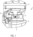
- a first embodiment of a weighing device according to the invention is a blast furnace hopper scale ( Fig. 1 ).
- the weighing device has a container 2 for receiving a liquid melt as a force absorber.
- the weighing device 1 has three load cells 3. Each of the three load cells 3 is arranged between the container 2 and a base plate 4.
- the container 2 is supported exclusively by the load cells 3, so that no force connection can occur parallel to the load cells 3.
- the base plate 4, which forms the base, is also referred to as the connection structure.
- the load cells 3 are rigidly connected to the container 2. In the present embodiment, they are screwed to the container 2. Elastomer bearings are often used in weighing devices to couple the respective load cell to the force absorption in order to decouple disruptive forces and to ensure that the force flow from the force absorption into the load cell 3 only occurs in the desired direction. Such elastomer bearings are maintenance-intensive. In addition, such elastomer bearings are sensitive to heat and it is therefore difficult to use them in a weighing device for melt from a blast furnace. The rigid connection requires significantly less maintenance than a coupling using elastomer bearings. However, the rigid connection between the load cells 3 and the container 2 has the disadvantage that disruptive forces can also act on the load cells 3, which may affect the measurement.
- the individual load cells 3 have strain gauges 5 as sensors.
- the strain gauges can be connected in a Wheatstone bridge, for example.
- the individual load cells 3 have a readout device with an A/D converter so that a digital measuring signal is output.
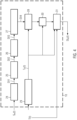
- the load cells 3 are each connected to a measuring signal collection station 7 via a data line 6 ( Fig. 2 ). At the measurement signal collection station 7, measurement signals from the individual load cells 3 are read in and combined with one another. In the present embodiment, the measurement signals from the three load cells 3 are added together, since the measuring arrangement is designed in such a way that all three load cells basically measure the same proportion of the load. However, the lever ratios with which the load acts on the respective load cell may differ, so that the measurement signals from the individual load cells must be multiplied by a factor in order to generate a correct overall signal.
- the measurement signal S m (t) generated by the measurement signal collection station 7 is transmitted to a central evaluation device 9 via a further data line 8.
- the central evaluation device 9 has a digital functional model 10 of the weighing device 1 ( Fig. 3 , 4 ).
- a signal is present which describes the weight M(t) measured by the weighing device 1.
- a signal is output which represents a simulated measurement signal sf m (t), whereby in the present embodiment, the simulated measurement signal is modified in such a way that the errors of the weighing device 1 are simulated, so that the simulated measurement signal is an errored measurement signal sf m (t).
- the functional model 10 represents a digital simulation of the weighing device 1, wherein the simulated measurement signal sf m (t) is output when a predetermined weight M(t) is applied.
- the digital functional model 10 can have one or more inputs for disturbances, which are taken into account when simulating the measurement signal.
- a signal representing the temperature T(t) at the load cells 3 is input as a disturbance variable into the digital functional model 10.
- the digital functional model 10 is part of an evaluation loop 14, which has an input 15 for receiving the measurement signal s m (t) from the measurement signal collection station 7.
- the input 15 is connected to a comparator 16.
- the comparator 16 is also connected to the output 12 of the digital functional model 10 and calculates the difference between the measured measurement signal s m (t) and the simulated error-prone measurement signal sf m (t) output by the functional model 10.
- the comparator 16 outputs a difference signal ⁇ s, which is forwarded to a downstream integrator 17.
- the integrator 17 integrates the difference signal ⁇ s and outputs the weight signal M(t).
- the output of the integrator 17 is connected to the input 11 of the digital functional model 10.
- an output 18 is provided at the connection between the integrator 17 and the digital functional model 10, which leads out of the central evaluation device 9 and at which the signal describing the weight M(t) is output.
- the digital functional model 10 is, as explained in more detail below, designed in such a way that, on the basis of the weight signal M(t) present at the input, the faulty measurement signal sf m (t) is generated.
- the digital functional model 10 thus simulates the systematic errors of the weighing device 1.
- the difference signal ⁇ s deviates from zero and by integrating using the integrator 17, the value of the weight signal M(t) rises or falls depending on the sign of the difference signal ⁇ s. If the measured measurement signal s m (t) matches the simulated error-prone measurement signal sf m (t), then the difference signal ⁇ s is zero, which means that the weight signal M(t) at the output of the integrator 17 is stable. This weight signal M(t) corresponds to the weight actually measured with the weighing device 1 and is output as a weight value at the output 18.
- the central evaluation device 9 further comprises a learning device, which in the present embodiment consists of an optimization module 18, a data logger 19 and a branch module 20 ( Fig. 3 ).
- the branch module 20 is arranged at the input 15 of the central evaluation device 9 and can branch off the measured measurement signal s m (t) and feed it via a data line 21 to the data logger 19 in which the measured measurement signals s m (t) are stored.
- the data logger 19 is connected via further data lines 22 and 23 to the output 12 of the functional model 10 and to the input 11 of the functional model 10 in order to read in the simulated error-prone measurement signal sf m (t) and the weight signal M(t).
- disturbances are detected, these disturbances are also read in synchronously with the reference measurement signals and weight signals and stored in the data logger 19.
- the optimization module has a data line 42 to the digital function model 10 in order to to transmit parameters determined by the optimization procedure to the digital functional model 10.
- the digital functional model 10 has a characteristic module 24 which is arranged directly at the input 11 of the digital functional model ( Fig. 4 ).
- the characteristic curve module converts the weight signal M(t) into a preliminary first measurement signal sv1(t) using a predetermined characteristic curve that corresponds to the characteristic curve of the weighing device 1.
- This function has a linear parameter Pl, a quadratic parameter Pq and a cubic parameter Pc.
- This function converts the weight value into a measurement signal sv1, which is a fictitious, essentially error-free measurement signal from the weighing device 1.
- the characteristic curve is thus approximated by a non-linear function. This corrects non-linearities of the real characteristic curve.
- the characteristic curve module 24 is followed by an error simulation module 25 for correcting the creep of a measuring body.
- the strain gauges 5 are attached to a measuring body that deforms under a load. The deformation of the measuring body is measured using the strain gauges 5. If the load on the measuring body continues for a longer period of time, the measuring body deforms increasingly. This is referred to as creep.
- the creep is simulated using a low-pass filter.
- a time constant P tau-kriech-mess is required for the creep of the measuring body.
- the time constant for the creep P tau-kriech-mess is to be determined using an optimization process.
- the error simulation module 25 for creep converts the first preliminary signal sv1 into a second preliminary signal sv2, whereby the measurement signal is changed according to the creep effect on the weighing device 1.
- the second preliminary measurement signal sv2 has thus been changed in accordance with how creep occurs in the weighing device 1.
- composition of the parameters may vary depending on the model.
- the hysteresis error simulation module 26 changes the preliminary second measurement signal sv2 to a preliminary third measurement signal sv3 according to the hysteresis effect occurring in the weighing device 1.
- the error simulation module 26 for the hysteresis is followed by an error simulation module 27 for the creep of the strain gauges 5.
- the creep of the strain gauges is simulated by a low-pass filter in combination with a correction term that is proportional to the derivative with respect to time t.
- a parameter P tau kriechDMS for the time constant of the creep of the strain gauges, which is to be determined using the optimization method, and a parameter P kriechDMS that describes a short-term overshoot of the measurement signal when the strain gauge creeps are required.
- a fourth preliminary measurement signal sv4 is generated using the error simulation module 27 for the creep of the strain gauges 5.
- the fourth preliminary measurement signal sv4 is fed to an error simulation module 28 for a zero point correction.
- the zero point is temperature dependent.
- the time-varying temperature signal T(t) is present in the functional model 10.
- the temperature signal T(t) is first filtered with a low-pass filter 29, which results in a delayed temperature value Tm(t) that corresponds to the temperature of the measuring body.
- sv5 sv4 + Ptk0 * Tm t ⁇ Tref )
- sv5 the fifth preliminary measurement signal
- Tref a reference temperature at which there is no deviation of the zero point
- Ptk0 a parameter to be set by means of the optimization procedure, which describes the change of the zero point depending on the deviation of the temperature from the reference temperature.
- the measuring sensitivity of the strain gauges 5 is temperature-dependent, which is why the fifth preliminary measuring signal sv5 is corrected to a sixth preliminary measuring signal sv6 by means of an error simulation module 30 for changing the sensitivity of the strain gauges.
- a temperature gradient leads to thermal stresses on the measuring body.
- the thermal stresses lead to deformations of the measuring body, which are recorded by the strain gauges 5 and cause a systematic measurement error. Therefore, the sixth preliminary measurement signal sv6 is fed to another error simulation module 31 to correct the influence due to the temperature gradient.
- the temperature value T(t) actually measured with the temperature sensor is also taken into account and the temperature difference between these two temperature values is calculated.
- the determination of the gradient value using the low-pass filter 29 is possible in weighing devices in which the heat flow is always in the same direction. If there is a heat flow in different directions, then it is expedient to use two or more temperature sensors in order to be able to determine the direction(s) of the heat flow.
- the weighing device is supplied with a reference signal.
- the reference signal can be generated, for example, by placing a calibration body with a predetermined weight on it.
- the calibration signal can also be generated by means of a mechanical force generating device, such as a pressure piston and a reference load cell which is applied to the weighing device, wherein the reference load cell is a high-precision load cell for measuring the reference signal.
- a weighing device such as that used in Figure 1 shown, with which large quantities of hot melt are to be weighed, it is expedient to use one or more reference pans, each with a predetermined weight, as reference weights.
- the central component of the learning device is the optimization module 18, which can receive the reference measurement signals by means of the branch module 20 and the data logger 19 and temporarily store them in the data logger 19 and at the same time records the weight signals M(t) generated by the evaluation loop 14.
- reference measurement signals s m-ref (t) are first calculated using one or more reference weights or a reference device, as used, for example, in Figure 6 shown.
- the reference measurement signals, the reference weights and, if applicable, the disturbance variables are stored in the data logger 19.
- the individual parameters P are varied on the digital functional model 10 so that the reference weight(s) are applied to the input 11 of the functional model 10 and the error-prone measurement signal sf m (t) simulated thereon is brought as closely as possible into line with the recorded stored reference measurement signals s m-ref (t).
- the evaluation loop 14 can generate a weight signal M(t) from the weight measurement signal s m (t), which is corrected with respect to the errors simulated by the individual error simulation modules.
- the error simulation modules could therefore also be referred to as correction modules.
- PSO particle swarm optimization
- Gradient-based methods are also suitable as optimization methods. In principle, however, non-gradient-based methods can also be used. Gradient-based methods include the gradient descent method, the gradient descent method with constraints or the quasi-Newton method. They only require a small deflection of the control parameters of the weighing device around its operating state.
- Gradient-based methods have the advantage that they provide a very precise model of the respective system for the environment of the operating state, which can be determined easily and quickly by deflecting a control parameter.
- Non-gradient-based methods include the Simplex-Nelder-Mead method or the differential evolution method. An overview of various optimization methods is given, for example, in the textbook Optimization by Florian Jarre and Josef Stör (DOI10.1007/978-3-642-18785-8).
- the optimization method is a gradient-based method or a non-gradient-based method, it is usually an iterative optimization method that optimizes the parameters step by step.
- the learning process can be carried out fully automatically. However, if different reference weights are applied manually, the learning process must be carried out semi-automatically and the reference weight applied must be entered at a suitable point on the central evaluation device 9.
- the digital functional model 10 shown is specifically designed for a weighing device.
- a general model instead of such a specific model, which is represented by a neural network, for example.
- the use of such a specific model requires significantly fewer reference values when learning, which makes learning much easier and faster. In individual cases, it may even be sufficient to only apply the zero load and another reference load when learning in order to fully train the digital functional model 10.
- all measured values, the corresponding disturbance variables and the reference loads are preferably recorded and stored synchronously in order to be available for the optimization process.
- the learning device 18, 19, 20 is integrated in the central evaluation device 9.
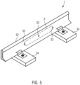
- a second embodiment of a weighing device 1 is a track scale, which has several load cells 3 along two rails 32 of a train track.
- Figure 5 shows schematically only a section of a single rail 32 with a schematic representation of the load cell 3.
- the load cell 3 has three strain gauges 33 which are glued to the track, whereby the load cell 3 is located in the area between two sleepers 34.
- Such a load cell 3 can also have more than three strain gauges 33. If the rail 32 is loaded in the area of the load cell 3, the rail 32 bends and this bending is recorded by the load cell 3.
- the rail 32 thus serves as a measuring body.
- This weighing device 1 can comprise a plurality of load cells 3 along two rails 32 of a track, which are attached to the rails 32 at regular intervals over a distance of 20 - 50 m, for example. This makes it possible to record the weight of a wagon on the track when the train is slowly traveling down it. In this case, several groups of load cells 3, which are arranged close to one another, are each connected to a central evaluation device 9, so that the individual groups of load cells 3 are recorded and evaluated independently of one another.
- FIG. 6 Another embodiment is a weighing device 1 for bogies of trains.
- Figure 6 is merely a single section of a rail 35 is shown, which rests on two load cells 3.
- the load cells 3 are in turn arranged on a base plate 36. There is no further connection between the rail 35 and the base plate 36, so that there is no force shunt to the load cells 3.
- the load cells 3 are rigidly connected to both the base plate 36 and the rail 35, ie they are either screwed or connected to one another with a press fit.
- a reference device is arranged on this weighing device 1, which comprises a pressure piston 37, a hydraulic cylinder 38 and a reference load cell 39.
- the reference load cell 39 is coupled to the pressure piston 37 and the hydraulic cylinder 38 by means of elastomer bearings.
- the hydraulic cylinder 38 is fastened at its upper end to a support plate 40, which is connected to the base plate 36 by support rods 41.
- the reference load cell 39 precisely measures the force exerted by the hydraulic cylinder 38 and generates a reference signal.
- the reference device After learning the parameters of the digital functional model, the reference device is removed and the weighing device can be used to weigh the bogies.
- Such weighing devices for bogies are usually arranged in halls in which defined temperature conditions exist. This weighing device is therefore subject to no or negligible temperature fluctuations.
- this weighing device 1 can be simulated very well with a digital functional model 10, which only has the characteristic curve module 24 and the error simulation module 26 for correcting the hysteresis effect. All other error simulation modules, which are used in the Figure 4 shown embodiment can be omitted.
- the characteristic curve module which approximates the characteristic curve with a cubic function, is used on the one hand to convert the weight signal into a measurement signal and on the other hand to compensate for any non-linearity of the characteristic curve.
- the individual fault simulation modules 25 - 31 can be switched on individually.
- the digital functional model can also be trained using a different combination of error simulation modules. This makes it possible to determine which error simulation modules are actually suitable for the respective weighing device are relevant in order to minimize the error. If, for example, it turns out that a certain error simulation module does not bring about any improvement in minimizing the error, then this means that the error corrected by this error simulation module does not occur in the corresponding weighing device.
- the invention can be briefly summarized as follows:
- the invention relates to a weighing device and a weighing method with a central digital measurement value correction.
- the weighing device is simulated on a central evaluation device with a digital functional model of the weighing device.
- the digital functional model of the weighing device can be taught using a learning device so that measurement errors of the weighing device are compensated.
- the measurement signal collection station 7 is arranged near the load cells 3.
- the measurement signal collection station is connected to the central evaluation device 9 by a data line 8, which is significantly longer than the data lines between the load cells 3 and the measurement signal collection station 7.
- the data line 8 can have a length of at least 10 m, in particular 20 m and in particular 30 m.
- the measurement signal collection station 7 can also be integrated into the central evaluation device 9 within the scope of the invention.
Landscapes
- Physics & Mathematics (AREA)
- General Physics & Mathematics (AREA)
- Nonlinear Science (AREA)
- Measurement Of Force In General (AREA)
- Indication And Recording Devices For Special Purposes And Tariff Metering Devices (AREA)
Claims (15)
- Dispositif de pesée (1) avec une correction numérique centrale des valeurs de mesure,qui comprend au moins une cellule de pesée (3)qui est relié à un dispositif d'évaluation central (9) via une ligne de signal et/ou de données (6,8) pour transmettre un signal de mesure de poids, le dispositif d'évaluation central comportant une unité d'évaluation pour déterminer la force mesurée avec le dispositif de pesée sur la base du signal de mesure de poids,caractérisé en ce que l'unité d'évaluation comprend un modèle fonctionnel numérique (10) du dispositif de pesée, qui présente un ouplusieurs modules de simulation d'erreurs, chaque module de simulation d'erreurs représentant un modèle du dispositif de pesée qui simule au moins une erreur de mesure spécifique du dispositif de pesée, et chaque module de simulation d'erreurs comportant un ou plusieurs paramètres de modèle avec lesquels le dispositif de pesée est modélisé, un dispositif d'apprentissage étant prévu pour déterminer les paramètres du modèle au cours d'un processus d'apprentissage dans lequel des signaux de mesure de référence sont générés à l'aide d'une ou plusieurs charges de référence,dans lequel le modèle fonctionnel présente un module de courbe caractéristique (24) qui convertit le signal de mesure de poids en un signal de poids ou vice versa et le module de courbe caractéristique présente des paramètres de courbe caractéristique qui sont déterminés au moyen du dispositif d'apprentissage pendant le processus d'apprentissage.
- Dispositif de pesée selon la revendication 1,
caractérisé en ce que
le module de courbe caractéristique est conçu pour convertir le signal de poids en un signal de mesure de poids et les modules de simulation d'erreurs pour simuler le signal de poids sont conçus de telle manière qu'ils modifient le signal de mesure de poids en raison d'une erreur qui se produit sur le dispositif de pesée. - Dispositif de pesée selon la revendication 1 ou 2, caractérisé en ce
qu'un module unique parmi les nombreux modules de simulation d'erreurs peut être désactivé. - Dispositif de pesée selon l'une des revendications 1 à 3, caractérisé en ce que le dispositif de pesée présente plusieurs cellules de pesée, les signaux provenant des cellules de pesée individuelles étant combinés pour former le signal de mesure de poids.
- Dispositif de pesée selon l'une des revendications 1 à 4, caractérisé en ce que la ou les cellules de pesée sont équipées d'une ou plusieurs jauges de contrainte.
- Dispositif de pesée selon l'une des revendications 1 à 5, caractérisé en ce que les cellules de pesée sont intégrées dans le dispositif de pesée avec des raccords rigides.
- Dispositif de pesée selon l'une des revendications 1 à 6, caractérisé en ce que le dispositif de pesée comporte un capteur de température qui est agencé sur ou à proximité d'au moins une des cellules de pesée pour détecter la température.
- Dispositif de pesée selon l'une des revendications 1 à 7, caractérisé en ce qu'au moins deux modules de simulation d'erreurs sont fournis pour corriger l'une des causes de défaillance suivantes :- la linéarité ;- le fluage (prise de force, cellule de pesée) ;- l'hystérésis ;- les écarts thermiques du point zéro ;- les écarts du point zéro par rapport à une température de 34 degrés ;- les écarts de sensibilité des cellules de pesée dus aux changements de température ;- les chocs ;- la position de la charge ;- les forces transversales ;- les erreurs due à l'inclinaison.
- Dispositif de pesée selon la revendication 8, caractérisé en ce que
le module de courbe caractéristique est conçu de telle sorte qu'il se rapproche de la courbe caractéristique du dispositif de pesée avec une fonction non linéaire. - Procédé de pesée avec correction numérique centrale des valeurs de mesure avec au moins une cellule de pesée (3) détectant un signal de mesure du poids (sm(t)) qui est transmis via une ligne de signal et/ou de données (6, 8) à un dispositif d'évaluation central (9), le dispositif d'évaluation central étant doté d'une unité d'évaluation qui détermine la force mesurée avec le dispositif de pesée (1) sur la base du signal de mesure de poids, le dispositif d'évaluation convertissant le signal de mesure de poids en un signal de poids caractérisé en ce qu'un modèle fonctionnel numérique (10) du dispositif de pesée est utilisé pour simuler l'appareil de pesée avec ses effets d'erreur afin de compenser les erreurs dans le signal de poids.
- Dispositif de pesée selon la revendication 10, caractérisé en ce que
le modèle fonctionnel numérique a été entraîné à l'avance avec un dispositif d'apprentissage au cours d'un processus d'apprentissage dans lequel des signaux de mesure de référence ont été générés à l'aide d'une ou plusieurs charges de référence. - Procédé de pesée selon la revendication 11, caractérisé en ce que
le processus d'apprentissage est basé sur un procédé d'optimisation itératif. - Dispositif de pesée selon l'une des revendications 10 à 12, caractérisé en ce
qu'un module de courbe caractéristique du modèle fonctionnel pour la simulation convertit le signal de mesure de poids en un signal de poids ou vice versa et le module de courbe caractéristique présente des paramètres de courbe caractéristique qui ont été déterminés à l'avance au moyen du processus d'apprentissage. - Procédé de pesée selon l'une des revendications 10 à 13, caractérisé en ce qu'un ou plusieurs modules de simulation d'erreurs du modèle fonctionnel numérique de l'appareil de pesée simulent chacun au moins une erreur de mesure spécifique de l'appareil de pesée, et à cet effet chaque module de simulation d'erreur utilise un ou plusieurs paramètres de modèle qui ont été déterminés à l'avance au moyen du processus d'apprentissage.
- Procédé selon l'une des revendications 10 à 14, caractérisé en ce qu'un dispositif de pesée est utilisé selon l'une des revendications 1 à 9.
Applications Claiming Priority (2)
| Application Number | Priority Date | Filing Date | Title |
|---|---|---|---|
| DE102021104430.8A DE102021104430A1 (de) | 2021-02-24 | 2021-02-24 | Wägevorrichtung und Wägeverfahren mit einer zentralen digitalen Messwertkorrektur |
| PCT/EP2022/054467 WO2022180066A1 (fr) | 2021-02-24 | 2022-02-23 | Dispositif et procédé de pesage, avec correction numérique centrale de la valeur mesurée |
Publications (3)
| Publication Number | Publication Date |
|---|---|
| EP4298410A1 EP4298410A1 (fr) | 2024-01-03 |
| EP4298410B1 true EP4298410B1 (fr) | 2025-01-01 |
| EP4298410C0 EP4298410C0 (fr) | 2025-01-01 |
Family
ID=80625277
Family Applications (1)
| Application Number | Title | Priority Date | Filing Date |
|---|---|---|---|
| EP22707431.7A Active EP4298410B1 (fr) | 2021-02-24 | 2022-02-23 | Dispositif de pesée et procédé de pesée avec une correction centrale de la valeur de mesure |
Country Status (6)
| Country | Link |
|---|---|
| US (1) | US20230400344A1 (fr) |
| EP (1) | EP4298410B1 (fr) |
| CN (1) | CN116888438A (fr) |
| DE (1) | DE102021104430A1 (fr) |
| ES (1) | ES3010166T3 (fr) |
| WO (1) | WO2022180066A1 (fr) |
Families Citing this family (2)
| Publication number | Priority date | Publication date | Assignee | Title |
|---|---|---|---|---|
| CN117804670B (zh) * | 2024-02-28 | 2024-06-14 | 深圳市沃感科技有限公司 | 一种板式压力传感器的误差修正方法及装置 |
| CN119783588B (zh) * | 2025-03-07 | 2025-07-15 | 一汽解放汽车有限公司 | 一种车辆风洞仿真模型建立方法、装置、设备及存储介质 |
Family Cites Families (11)
| Publication number | Priority date | Publication date | Assignee | Title |
|---|---|---|---|---|
| GB1495278A (en) | 1975-06-13 | 1977-12-14 | Avery Ltd W & T | Compensation for weight-independent parameters in weighin |
| US5623128A (en) | 1994-03-01 | 1997-04-22 | Mettler-Toledo, Inc. | Load cell with modular calibration components |
| DE4443050C2 (de) | 1994-12-05 | 1997-08-07 | Schenck Ag Carl | Einrichtung zum Kalibrieren einer Kraftmeßeinrichtung |
| JPH1137827A (ja) | 1997-07-16 | 1999-02-12 | A & D Co Ltd | 荷重測定装置 |
| EP1736746B1 (fr) | 2005-06-21 | 2012-08-01 | Mettler-Toledo AG | Procédé pour optimiser le comportement d'un dispositif de mesure de force et dispositif de mesure de force servant à la mise en ouvre de ce procèdè. |
| DE102006009005A1 (de) | 2006-02-23 | 2007-08-30 | Schenck Process Gmbh | Verfahren zum Austauschen von Wägezellen |
| EP2278283A1 (fr) * | 2009-07-23 | 2011-01-26 | Mettler-Toledo AG | Procédé de correction de température d'un dispositif de mesure de force et dispositif de mesure de force |
| EP2278286A1 (fr) | 2009-07-23 | 2011-01-26 | Mettler-Toledo AG | Procédé de détermination de grandeurs de processus pour un dispositif de mesure de force et dispositif de mesure de force |
| EP3066442A1 (fr) * | 2013-11-04 | 2016-09-14 | Nextnav, LLC | Déterminer des mesures de pression calibrées pour différents capteurs |
| CN112304412B (zh) * | 2019-07-31 | 2022-05-31 | 梅特勒-托利多(常州)测量技术有限公司 | 称重装置的滞后补偿方法 |
| CN111829638B (zh) * | 2020-07-24 | 2022-03-18 | 福建世新机器人科技有限公司 | 一种体重实时测量方法 |
-
2021
- 2021-02-24 DE DE102021104430.8A patent/DE102021104430A1/de active Pending
-
2022
- 2022-02-23 WO PCT/EP2022/054467 patent/WO2022180066A1/fr not_active Ceased
- 2022-02-23 ES ES22707431T patent/ES3010166T3/es active Active
- 2022-02-23 EP EP22707431.7A patent/EP4298410B1/fr active Active
- 2022-02-23 CN CN202280016882.3A patent/CN116888438A/zh active Pending
-
2023
- 2023-08-24 US US18/237,713 patent/US20230400344A1/en active Pending
Also Published As
| Publication number | Publication date |
|---|---|
| EP4298410A1 (fr) | 2024-01-03 |
| DE102021104430A1 (de) | 2022-08-25 |
| US20230400344A1 (en) | 2023-12-14 |
| KR20230147718A (ko) | 2023-10-23 |
| WO2022180066A1 (fr) | 2022-09-01 |
| ES3010166T3 (en) | 2025-04-01 |
| EP4298410C0 (fr) | 2025-01-01 |
| CN116888438A (zh) | 2023-10-13 |
Similar Documents
| Publication | Publication Date | Title |
|---|---|---|
| EP1736745B1 (fr) | Procédé de correction adaptatif de la derive associés à un dispositif de mesure de force et dispositif de mesure de force servant à la mise en ouvre de ce procédé. | |
| DE112010003522B4 (de) | Vorrichtung und Verfahren zumn Steuern einer Wageeinrichtung fur elektronische Bandwaagen | |
| EP0340316B1 (fr) | Procédé de calibrage pour la balance interne d'une soufflerie | |
| EP2457070B1 (fr) | Procédé de correction des errors de température d'un dispositif de mesure de force et dispositif de mesure de force correspondant | |
| DE102009002392A1 (de) | System und Verfahren zur Bestimmung von lokalen Beschleunigungen, dynamischen Lastverteilungen und aerodynamischen Daten bei einem Luftfahrzeug | |
| EP2784453B1 (fr) | Linéarisation numérique de cellules de balances | |
| EP2202498A2 (fr) | Dispositif de compensation de choc du signal de poids d'un capteur de pesée | |
| DE2904261C2 (de) | Elektronische Waage, insb. Ladenwaage | |
| EP4298410A1 (fr) | Dispositif et procédé de pesage, avec correction numérique centrale de la valeur mesurée | |
| AT393911B (de) | Muellmengenwaegevorrichtung | |
| EP0271644B1 (fr) | Procédé pour linéariser une balance électronique | |
| DE69117775T2 (de) | Verfahren und gerät zum wiegen einer last | |
| DE3719532A1 (de) | Kraftmesseinrichtung | |
| EP0500971B1 (fr) | Méthode de pesage | |
| DE102005018708A1 (de) | Wägevorrichtung, insbesondere Mehrspur-Wägevorrichtung | |
| DE2926213A1 (de) | Pyramidenwaage zur ermittlung von kraeften und momenten, insbesondere in windkanaelen | |
| DE102019122383A1 (de) | Digitale Messwertkorrektur bei einer in einer Anschlussstruktur eingebauten Kraftmessvorrichtung | |
| KR102968379B1 (ko) | 중앙 디지털 측정 값 보정을 갖는, 칭량 디바이스 및 칭량 방법 | |
| DE102023121556A1 (de) | Verfahren zur Kompensation eines Sensors | |
| DE10053667A1 (de) | Verfahren und Vorrichtung zur Hysteresekorrektur von Meßwerten bei Aufnehmern mit Dehnungsmeßstreifen | |
| EP1456685A1 (fr) | Appareil de terrain comportant un module gps | |
| DE3873901T4 (de) | Vorrichtung zur Messung des Gewichts. | |
| EP1826540B1 (fr) | Procédé destiné à remplacer des cellules de charge | |
| DE102021120557B4 (de) | Kalibriersystem | |
| DE4244394C2 (de) | Schnittstelle bei eichfähigen elektromechanischen Waagen |
Legal Events
| Date | Code | Title | Description |
|---|---|---|---|
| STAA | Information on the status of an ep patent application or granted ep patent |
Free format text: STATUS: UNKNOWN |
|
| STAA | Information on the status of an ep patent application or granted ep patent |
Free format text: STATUS: THE INTERNATIONAL PUBLICATION HAS BEEN MADE |
|
| PUAI | Public reference made under article 153(3) epc to a published international application that has entered the european phase |
Free format text: ORIGINAL CODE: 0009012 |
|
| STAA | Information on the status of an ep patent application or granted ep patent |
Free format text: STATUS: REQUEST FOR EXAMINATION WAS MADE |
|
| 17P | Request for examination filed |
Effective date: 20230906 |
|
| AK | Designated contracting states |
Kind code of ref document: A1 Designated state(s): AL AT BE BG CH CY CZ DE DK EE ES FI FR GB GR HR HU IE IS IT LI LT LU LV MC MK MT NL NO PL PT RO RS SE SI SK SM TR |
|
| DAV | Request for validation of the european patent (deleted) | ||
| DAX | Request for extension of the european patent (deleted) | ||
| GRAP | Despatch of communication of intention to grant a patent |
Free format text: ORIGINAL CODE: EPIDOSNIGR1 |
|
| STAA | Information on the status of an ep patent application or granted ep patent |
Free format text: STATUS: GRANT OF PATENT IS INTENDED |
|
| INTG | Intention to grant announced |
Effective date: 20240913 |
|
| GRAS | Grant fee paid |
Free format text: ORIGINAL CODE: EPIDOSNIGR3 |
|
| GRAA | (expected) grant |
Free format text: ORIGINAL CODE: 0009210 |
|
| STAA | Information on the status of an ep patent application or granted ep patent |
Free format text: STATUS: THE PATENT HAS BEEN GRANTED |
|
| AK | Designated contracting states |
Kind code of ref document: B1 Designated state(s): AL AT BE BG CH CY CZ DE DK EE ES FI FR GB GR HR HU IE IS IT LI LT LU LV MC MK MT NL NO PL PT RO RS SE SI SK SM TR |
|
| RAP3 | Party data changed (applicant data changed or rights of an application transferred) |
Owner name: QLAR EUROPE GMBH |
|
| REG | Reference to a national code |
Ref country code: GB Ref legal event code: FG4D Free format text: NOT ENGLISH |
|
| REG | Reference to a national code |
Ref country code: CH Ref legal event code: EP |
|
| REG | Reference to a national code |
Ref country code: DE Ref legal event code: R096 Ref document number: 502022002582 Country of ref document: DE |
|
| REG | Reference to a national code |
Ref country code: IE Ref legal event code: FG4D Free format text: LANGUAGE OF EP DOCUMENT: GERMAN |
|
| U01 | Request for unitary effect filed |
Effective date: 20250110 |
|
| U07 | Unitary effect registered |
Designated state(s): AT BE BG DE DK EE FI FR IT LT LU LV MT NL PT RO SE SI Effective date: 20250117 |
|
| REG | Reference to a national code |
Ref country code: ES Ref legal event code: FG2A Ref document number: 3010166 Country of ref document: ES Kind code of ref document: T3 Effective date: 20250401 |
|
| RAP4 | Party data changed (patent owner data changed or rights of a patent transferred) |
Owner name: QLAR EUROPE GMBH |
|
| U1H | Name or address of the proprietor changed after the registration of the unitary effect |
Owner name: QLAR EUROPE GMBH; DE |
|
| U20 | Renewal fee for the european patent with unitary effect paid |
Year of fee payment: 4 Effective date: 20250325 |
|
| PG25 | Lapsed in a contracting state [announced via postgrant information from national office to epo] |
Ref country code: PL Free format text: LAPSE BECAUSE OF FAILURE TO SUBMIT A TRANSLATION OF THE DESCRIPTION OR TO PAY THE FEE WITHIN THE PRESCRIBED TIME-LIMIT Effective date: 20250101 |
|
| PGFP | Annual fee paid to national office [announced via postgrant information from national office to epo] |
Ref country code: ES Payment date: 20250331 Year of fee payment: 4 |
|
| PG25 | Lapsed in a contracting state [announced via postgrant information from national office to epo] |
Ref country code: IS Free format text: LAPSE BECAUSE OF FAILURE TO SUBMIT A TRANSLATION OF THE DESCRIPTION OR TO PAY THE FEE WITHIN THE PRESCRIBED TIME-LIMIT Effective date: 20250501 Ref country code: NO Free format text: LAPSE BECAUSE OF FAILURE TO SUBMIT A TRANSLATION OF THE DESCRIPTION OR TO PAY THE FEE WITHIN THE PRESCRIBED TIME-LIMIT Effective date: 20250401 |
|
| PG25 | Lapsed in a contracting state [announced via postgrant information from national office to epo] |
Ref country code: HR Free format text: LAPSE BECAUSE OF FAILURE TO SUBMIT A TRANSLATION OF THE DESCRIPTION OR TO PAY THE FEE WITHIN THE PRESCRIBED TIME-LIMIT Effective date: 20250101 |
|
| PG25 | Lapsed in a contracting state [announced via postgrant information from national office to epo] |
Ref country code: GR Free format text: LAPSE BECAUSE OF FAILURE TO SUBMIT A TRANSLATION OF THE DESCRIPTION OR TO PAY THE FEE WITHIN THE PRESCRIBED TIME-LIMIT Effective date: 20250402 |
|
| PG25 | Lapsed in a contracting state [announced via postgrant information from national office to epo] |
Ref country code: SM Free format text: LAPSE BECAUSE OF FAILURE TO SUBMIT A TRANSLATION OF THE DESCRIPTION OR TO PAY THE FEE WITHIN THE PRESCRIBED TIME-LIMIT Effective date: 20250101 |
|
| PG25 | Lapsed in a contracting state [announced via postgrant information from national office to epo] |
Ref country code: MC Free format text: LAPSE BECAUSE OF FAILURE TO SUBMIT A TRANSLATION OF THE DESCRIPTION OR TO PAY THE FEE WITHIN THE PRESCRIBED TIME-LIMIT Effective date: 20250101 |
|
| PG25 | Lapsed in a contracting state [announced via postgrant information from national office to epo] |
Ref country code: SK Free format text: LAPSE BECAUSE OF FAILURE TO SUBMIT A TRANSLATION OF THE DESCRIPTION OR TO PAY THE FEE WITHIN THE PRESCRIBED TIME-LIMIT Effective date: 20250101 |
|
| PLBE | No opposition filed within time limit |
Free format text: ORIGINAL CODE: 0009261 |
|
| STAA | Information on the status of an ep patent application or granted ep patent |
Free format text: STATUS: NO OPPOSITION FILED WITHIN TIME LIMIT |
|
| REG | Reference to a national code |
Ref country code: CH Ref legal event code: L10 Free format text: ST27 STATUS EVENT CODE: U-0-0-L10-L00 (AS PROVIDED BY THE NATIONAL OFFICE) Effective date: 20251112 |
|
| 26N | No opposition filed |
Effective date: 20251002 |
|
| PG25 | Lapsed in a contracting state [announced via postgrant information from national office to epo] |
Ref country code: IE Free format text: LAPSE BECAUSE OF NON-PAYMENT OF DUE FEES Effective date: 20250223 |
|
| REG | Reference to a national code |
Ref country code: CH Ref legal event code: U11 Free format text: ST27 STATUS EVENT CODE: U-0-0-U10-U11 (AS PROVIDED BY THE NATIONAL OFFICE) Effective date: 20260301 |
|
| U20 | Renewal fee for the european patent with unitary effect paid |
Year of fee payment: 5 Effective date: 20260225 |
|
| PGFP | Annual fee paid to national office [announced via postgrant information from national office to epo] |
Ref country code: TR Payment date: 20260217 Year of fee payment: 5 |
|
| PGFP | Annual fee paid to national office [announced via postgrant information from national office to epo] |
Ref country code: CZ Payment date: 20260217 Year of fee payment: 5 Ref country code: CH Payment date: 20260301 Year of fee payment: 5 |