EP4299026A1 - Appareil de ponction transseptale sur la base de l'impédance - Google Patents
Appareil de ponction transseptale sur la base de l'impédance Download PDFInfo
- Publication number
- EP4299026A1 EP4299026A1 EP23182157.0A EP23182157A EP4299026A1 EP 4299026 A1 EP4299026 A1 EP 4299026A1 EP 23182157 A EP23182157 A EP 23182157A EP 4299026 A1 EP4299026 A1 EP 4299026A1
- Authority
- EP
- European Patent Office
- Prior art keywords
- electrode
- dilator
- impedance
- guidewire
- distal
- Prior art date
- Legal status (The legal status is an assumption and is not a legal conclusion. Google has not performed a legal analysis and makes no representation as to the accuracy of the status listed.)
- Pending
Links
Images





Classifications
-
- A—HUMAN NECESSITIES
- A61—MEDICAL OR VETERINARY SCIENCE; HYGIENE
- A61B—DIAGNOSIS; SURGERY; IDENTIFICATION
- A61B18/00—Surgical instruments, devices or methods for transferring non-mechanical forms of energy to or from the body
- A61B18/04—Surgical instruments, devices or methods for transferring non-mechanical forms of energy to or from the body by heating
- A61B18/12—Surgical instruments, devices or methods for transferring non-mechanical forms of energy to or from the body by heating by passing a current through the tissue to be heated, e.g. high-frequency current
- A61B18/14—Probes or electrodes therefor
-
- A—HUMAN NECESSITIES
- A61—MEDICAL OR VETERINARY SCIENCE; HYGIENE
- A61B—DIAGNOSIS; SURGERY; IDENTIFICATION
- A61B18/00—Surgical instruments, devices or methods for transferring non-mechanical forms of energy to or from the body
- A61B18/04—Surgical instruments, devices or methods for transferring non-mechanical forms of energy to or from the body by heating
- A61B18/12—Surgical instruments, devices or methods for transferring non-mechanical forms of energy to or from the body by heating by passing a current through the tissue to be heated, e.g. high-frequency current
- A61B18/14—Probes or electrodes therefor
- A61B18/1492—Probes or electrodes therefor having a flexible, catheter-like structure, e.g. for heart ablation
-
- A—HUMAN NECESSITIES
- A61—MEDICAL OR VETERINARY SCIENCE; HYGIENE
- A61B—DIAGNOSIS; SURGERY; IDENTIFICATION
- A61B18/00—Surgical instruments, devices or methods for transferring non-mechanical forms of energy to or from the body
- A61B2018/00315—Surgical instruments, devices or methods for transferring non-mechanical forms of energy to or from the body for treatment of particular body parts
- A61B2018/00345—Vascular system
- A61B2018/00351—Heart
-
- A—HUMAN NECESSITIES
- A61—MEDICAL OR VETERINARY SCIENCE; HYGIENE
- A61B—DIAGNOSIS; SURGERY; IDENTIFICATION
- A61B18/00—Surgical instruments, devices or methods for transferring non-mechanical forms of energy to or from the body
- A61B2018/00315—Surgical instruments, devices or methods for transferring non-mechanical forms of energy to or from the body for treatment of particular body parts
- A61B2018/00345—Vascular system
- A61B2018/00351—Heart
- A61B2018/0038—Foramen ovale
-
- A—HUMAN NECESSITIES
- A61—MEDICAL OR VETERINARY SCIENCE; HYGIENE
- A61B—DIAGNOSIS; SURGERY; IDENTIFICATION
- A61B18/00—Surgical instruments, devices or methods for transferring non-mechanical forms of energy to or from the body
- A61B2018/00571—Surgical instruments, devices or methods for transferring non-mechanical forms of energy to or from the body for achieving a particular surgical effect
- A61B2018/00601—Cutting
-
- A—HUMAN NECESSITIES
- A61—MEDICAL OR VETERINARY SCIENCE; HYGIENE
- A61B—DIAGNOSIS; SURGERY; IDENTIFICATION
- A61B18/00—Surgical instruments, devices or methods for transferring non-mechanical forms of energy to or from the body
- A61B2018/00636—Sensing and controlling the application of energy
- A61B2018/00696—Controlled or regulated parameters
- A61B2018/00702—Power or energy
-
- A—HUMAN NECESSITIES
- A61—MEDICAL OR VETERINARY SCIENCE; HYGIENE
- A61B—DIAGNOSIS; SURGERY; IDENTIFICATION
- A61B18/00—Surgical instruments, devices or methods for transferring non-mechanical forms of energy to or from the body
- A61B2018/00636—Sensing and controlling the application of energy
- A61B2018/00773—Sensed parameters
- A61B2018/00875—Resistance or impedance
-
- A—HUMAN NECESSITIES
- A61—MEDICAL OR VETERINARY SCIENCE; HYGIENE
- A61B—DIAGNOSIS; SURGERY; IDENTIFICATION
- A61B18/00—Surgical instruments, devices or methods for transferring non-mechanical forms of energy to or from the body
- A61B18/04—Surgical instruments, devices or methods for transferring non-mechanical forms of energy to or from the body by heating
- A61B18/12—Surgical instruments, devices or methods for transferring non-mechanical forms of energy to or from the body by heating by passing a current through the tissue to be heated, e.g. high-frequency current
- A61B18/14—Probes or electrodes therefor
- A61B2018/1405—Electrodes having a specific shape
- A61B2018/1425—Needle
Definitions
- the present invention is directed toward methods and instruments for performing diagnostic or therapeutic procedures on tissue and organs, in particular, methods and instruments for perforation procedures such as a transseptal perforation procedure.
- Cardiac arrhythmias such as atrial fibrillation, occur when regions of cardiac tissue abnormally conduct electric signals. Procedures for treating arrhythmia include surgically disrupting the conducting pathway for such signals.
- electrical energy e.g., radiofrequency (AC type) or irreversible electroporation (IRE), such as pulsed field (DC type) energy
- AC type radiofrequency
- IRE irreversible electroporation
- DC type pulsed field
- the ablation process may provide a barrier to unwanted electrical pathways by creating electrically insulative lesions or scar tissue that effectively block communication of aberrant electrical signals across the tissue.
- a catheter with one or more electrodes may be used to provide ablation within the cardiovascular system.
- the catheter may be inserted into a major vein or artery (e.g., the femoral artery) and then advanced to position the electrodes within the heart or in a cardiovascular structure adjacent to the heart (e.g., the pulmonary vein).
- the one or more electrodes may be placed in contact with cardiac tissue or other vascular tissue and then activated with electrical energy to thereby ablate the contacted tissue.
- the electrodes may be bipolar.
- a monopolar electrode may be used in conjunction with a ground pad or other reference electrode that is in contact with the patient. Irrigation may be used to draw heat from ablating components of an ablation catheter; and to prevent the formation of blood clots near the ablation site.
- Atrial septum it may be desirable to traverse the atrial septum to facilitate access various types of cardiac interventions in the left atrium of the heart, including electrophysiological or structural testing, treatment (e.g., ablation), or mapping.
- electrophysiological or structural testing e.g., ablation
- mapping e.g., mapping
- a needle, guidewire, or other instrument may be used to form an opening through the septum. Examples of transseptal needles and associated components are disclosed in U.S. Pat. No 6,994,094, entitled “Method and Device for Transseptal Facilitation Based on Traum Patterns," issued February 7, 2006 , the disclosure of which is incorporated by reference herein, in its entirety; U.S. Pat.
- transseptal needle instruments include a dilation feature that further expands the opening formed through the atrial septum.
- Tissue puncture using an electrically active guidewire is disclosed in U.S. Application Serial No. 17/743,852, entitled “Tissue Puncture Using High Articulation Microcatheter and Electrically Active Guidewire,” filed May 13, 2022 , the disclosure of which is incorporated herein by reference, in its entirety.
- Some transseptal puncturing systems include, for example, a steerable microcatheter, a dilator, a sheath or a guidewire, along with a navigation module and an impedance monitoring module.
- the system and related method provide for a microcatheter with a location sensor, the guidewire with an electrically conductive ablation distal end, where the navigation module can be configured to determine a position of the distal end of the microcatheter based at least in part on the location sensor in reference to the distal end of the guidewire.
- the system and related method further provide for (i) measuring an impedance at the electrically-conductive ablation distal end of the guidewire [0018], (ii) determining a position of the ablation distal end of the guidewire based at least in part on the impedance[0025], and (iii) detecting contact of the ablation distal end with tissue based at least in part on the impedance [0026].
- initiating application of and terminating electrical energy to the ablation distal end of the guidewire can be based at least in part on the impedance.
- Embodiments of the present invention are directed to transseptal puncture systems and methods that use a guiding instrument, and an atraumatic puncture instrument longitudinally movable therein, with a first electrode configured for ablation and a second electrode electrically insulated from the first electrode.
- An impedance monitoring module is configured to measure an impedance at at least the second electrode, and an electrical generator is configured to selectively apply electrical energy to the first electrode based at least in part on the measured impedance at the second electrode.
- impedance measurements at both the first and second electrodes are used to determine relative positions of the instruments in the approach, contact, ablation and puncture of the septum.
- a transseptal puncture system include a lumened instrument, a needle instrument, an electrical generator and an impedance monitoring module.
- the needle instrument is advanced distally relative to a distal end of the lumened instrument to contact and ablate tissue, including a septum, via an electrically-conductive element or first electrode in puncturing the septum to enter a left atrium.
- the needle instrument advantageously includes a second electrode configured for impedance measurement, and the system is configured to determine position of the needle instrument based at least in part on a measured impedance at the second electrode.
- the system determines position of the needle instrument at various stages of a transseptal puncture procedure, including approach, contact, penetration, perforation or passage through the septum, based at least in part on the measured impedance at the second electrode.
- the first and second electrodes are separated by a predetermined distance.
- the first and second electrodes are electrically insulated from each other.
- the second electrode is proximal of the first electrode on the needle instrument.
- the second electrode and the first electrodes generally share a common longitudinal location on the needle instrument.
- the second electrode is nonablating.
- the system includes a return pad.
- the first electrode includes a ring electrode.
- the first electrode includes a distal tip electrode.
- the first electrode includes a distal dome electrode.
- a distal end of the needle instrument is atraumatic.
- a distal end of the needle instrument is lacking a piercing configuration.
- the second electrode includes a ring electrode.
- the system includes a navigation module.
- the impedance monitoring module is communication with the electrical generator, in electrical communication with the second electrode and configured to measure impedance at the second electrode.
- the electrical generator can be configured to provide electrical energy to the first electrode based at least in part on the impedance measured at the proximal electrode by the impedance monitoring module.
- a transseptal puncture method includes steering a lumened instrument that guides a needle instrument advanced therethrough to a target puncture site then puncturing the target puncture site with the needle instrument.
- the method includes applying electrical energy to an electrically-conductive element or first electrode of the needle instrument for ablating the target puncture site in penetrating tissue and measuring impedance at a second electrode for determining position of the needle instrument in various stages of a transseptal puncture procedure, including approach, contact, penetration or passage through the septum.
- the method includes applying electrical energy to the first electrode based in part on an impedance measured at the second electrode.
- the method includes suspending application of electrical energy to the first electrode based in part on an impedance measured at the second electrode.
- the method includes measuring impedance at the first electrode to determine an increase in impedance.
- the method includes measuring impedance at the first electrode to determine a decrease in impedance.
- the method includes measuring impedance at the second electrode to determine an increase in impedance.
- the method includes measuring impedance at the second electrode to determine a decrease in impedance.
- the method includes measuring impedance at the first electrode and comparing a measured impedance to a predetermined threshold.
- the method includes measuring impedance at the second electrode and comparing a measured impedance to a predetermined threshold
- a transseptal puncture method includes steering a lumened instrument that guides a needle instrument advanced therethrough to a target puncture site then puncturing the target puncture site with the needle instrument via ablation by selectively applying electrical energy to the needle instrument.
- the needle instrument includes a first electrode configured to ablate tissue and a second electrode electrically insulated from the first electrode.
- the method includes measuring impedance at the second electrode, including increase and decrease of impedance, and selectively applying electrical energy to the first electrode in response to the increase and the decrease of impedance measured.
- the method includes measuring impedances at the first electrode and the second electrode and comparing measured impedances of the first electrode and of the second electrode and of a predetermined threshold in determining relative position of the needle instrument in various stages of a transseptal puncture procedure, including approach, contact, penetration or passage through the septum from a first atrium to a second atrium.
- the method includes comparing the measured impedance of the first electrode and the measured impedance of the second electrode with each other.
- the method includes comparing the measured impedance of the first electrode and the predetermined threshold to each other.
- the method includes comparing the measured impedance of the second electrode and the predetermined threshold to each other.
- the method includes determining a baseline impedance for an electrode devoid of contact with septum tissue or blood.
- the predetermined threshold is a measured impedance of an electrode in contact with septum tissue.
- a transseptal puncture system in some embodiments, includes a guiding instrument configured with a lumen, and an elongated instrument configured to move longitudinally within the lumen, the instrument having a distal end and including a first electrode configured for ablation and a second electrode electrically insulated from the first electrode.
- the system also includes an impedance monitoring module configured to measure an impedance at the second electrode, and an electrical generator configured to selectively apply electrical energy to the first electrode based at least in part on the measured impedance.
- the guiding instrument includes a guiding sheath.
- the elongated instrument includes a needle instrument.
- the first electrode is distal of the second electrode.
- the first electrode is configured as a monopolar electrode for tissue ablation.
- the first electrode is configured as a bipolar electrode for tissue ablation.
- the first electrode and the second electrode are separate on the elongated instrument by a predetermined distance.
- the system includes a return pad that is configured to be affixed to a patient's body to enable the impedance monitoring module to measure impedance at the second electrode.
- electrical energy applied to the second electrode generates a current that is distributed through the patient's body to the return pad.
- a method of transseptal puncture includes positioning a guiding instrument near a septum, a needle instrument positioned in a lumen of the guiding instrument, the needle instrument including a first electrode and a second electrode. The method also includes deploying the needle instrument from the lumen with distal advancement relative to the guiding instrument, and measuring an impedance at at least one of the first and second electrodes. The method further includes selectively energizing the first electrode to ablate the septum in creating a puncture in the septum based on the impedance measured.
- the measuring an impedance includes measuring at the second electrode an increase in the impedance measured.
- the measuring an impedance at the second electrode includes measuring a decrease in the impedance measured.
- the measuring an impedance at the second electrode includes measuring an increase in impedance following a decrease in impedance
- the selectively energizing the first electrode includes suspending energization of the first electrode upon measuring the decrease in impedance
- the method further includes suspending distal advancement of the needle instrument upon measuring an impedance at the second electrode that includes an increase following by a decrease.
- a method of determining position of a needle instrument relative to a guiding sheath and a septum includes the needle instrument to include a first electrode and a second electrode, the first electrode configured to puncture the septum via ablation.
- the method includes providing a predetermined threshold impedance, determining a first measured impedance of the first electrode, determining a second measured impedance of the second electrode, comparing the first measured impedance with the predetermined threshold impedance, and comparing the second measured impedance with the predetermined threshold impedance.
- the method further includes selectively providing electrical energy to the first electrode for ablation when at least the first measured impedance is equal to the predetermined threshold impedance.
- the method further includes suspending electrical energy to the first electrode when at least the second measure impedance decreases following an increase.
- the method further includes selectively providing electrical energy to the first electrode for ablation when at least the second measured impedance is less than the predetermined threshold impedance.
- the terms “about” or “approximately” for any numerical values or ranges indicate a suitable dimensional tolerance that allows the part or collection of components to function for its intended purpose as described herein. More specifically, “about” or “approximately” may refer to the range of values ⁇ 20% of the recited value, e.g. “about 90%” may refer to the range of values from 71 % to 99%.
- the terms “patient,” “host,” “user,” and “subject” refer to any human or animal subject and are not intended to limit the systems or methods to human use, although use of the subject invention in a human patient represents a preferred embodiment.
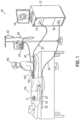
- FIG. 1 shows an exemplary medical procedure and associated components of a cardiac catheter system that may be used to provide EP mapping or cardiac ablation as referred to above.
- FIG. 1 shows a physician (PH) grasping a handle assembly (110) of a catheter assembly (100), with an end effector (not shown) of a catheter of catheter assembly (100) disposed in a patient (PA) to map potentials in tissue and/or ablate tissue in or near the heart (H) of the patient (PA).
- PH physician grasping a handle assembly (110) of a catheter assembly (100), with an end effector (not shown) of a catheter of catheter assembly (100) disposed in a patient (PA) to map potentials in tissue and/or ablate tissue in or near the heart (H) of the patient (PA).
- the end effector may include various electrodes, sensors, and/or other features that are configured to deliver electrical energy (e.g., RF or IRE, etc.) to targeted tissue sites, provide EP mapping functionality, track external forces imparted on the end effector, track the location of end effector, and/or disperse fluid.
- the catheter assembly (100) includes a needle instrument, for example, a guidewire, with an electrically-conductive ablation distal end to form an opening in the septum, and a sheath to guide the needle instrument to the septum, where the needle instrument includes an nonablating electrode that is proximal of the ablation distal end and configured to generate impedance signals.
- Catheter assembly (100) is coupled with a guidance and drive system (10) via a cable (30).
- Catheter assembly (100) is also coupled with a fluid source (42) via a fluid conduit (40).
- a set of field generators (20) are positioned underneath the patient (PA) and are coupled with guidance and drive system (10) via another cable (22).
- Magnetic field generators (20) are merely optional.
- Guidance and drive system (10) of the present example include a console (12) and a display (18).
- Console (12) includes a first driver module (14) and a second driver module (16).
- First driver module (14) is coupled with catheter assembly (100) via cable (30).
- first driver module (14) is operable to receive EP mapping signals obtained via microelectrodes of the end effector of catheter assembly (100).
- first driver module (14) includes a navigation module that is in connection with catheter assembly location sensor(s) and operable to determine a position of catheter components in the heart based at least in part on the location sensor(s) in reference to the electrically conductive distal end of the needle instrument.
- Console (12) includes a processor (not shown) that processes such EP mapping signals and thereby provides EP mapping as is known in the art.
- First driver module (14) of the present example is further operable to provide electrical energy to a distal tip member of the end effector of catheter assembly (100), to thereby ablate tissue.
- Second driver module (16) is coupled with magnetic field generators (20) via cable (22).
- Second driver module (16) is operable to activate magnetic field generators (20) to generate an alternating magnetic field around the heart (H) of the patient (PA).
- field generators (20) may include coils that generate alternating magnetic fields in a predetermined working volume that contains the heart (H).
- First driver module (14) is also operable to receive position indicative signals from a navigation sensor assembly in or near the end effector of catheter assembly (100).
- the processor of console (12) is also operable to process the position indicative signals from the navigation sensor assembly to thereby determine the position of the end effector of catheter assembly (100) within the patient (PA).
- the navigation sensor assembly includes two or more coils that are operable to generate signals that are indicative of the position and orientation of the end effector of catheter assembly (100) within the patient (PA). The coils are configured to generate electrical signals in response to the presence of an alternating electromagnetic field generated by magnetic field generators (20).
- first driver module (14) includes an impedance monitoring module and the processor of console (12) is also operable to process impedance signals from the electrically-conductive distal end of the needle instrument and the proximal electrode of the needle instrument, such as a guidewire, to thereby determine within the patient (PA) (i) whether the distal end of needle instrument is inside the guiding sheath or outside exposed to blood, (ii) if the distal end of the needle instrument has crossed the septum tissue; and (iii) location and direction of needle instrument.
- the electrical generator 306 can be configured to provide electrical energy to the distal electrode (1145) based at least in part on one or more impedances measured by the impedance monitoring module of the first driver module (14).
- Display (18) is coupled with the processor of console (12) and is operable to render images of patient anatomy. Such images may be based on a set of preoperatively or intraoperatively obtained images (e.g., a CT or MRI scan, 3-D map, etc.).
- the views of patient anatomy provided through display (18) may also change dynamically based on signals from the navigation sensor assembly of the end effector of catheter assembly (100). For instance, as the end effector of catheter assembly (100) moves within the patient (PA), the corresponding position data from the navigation sensor assembly may cause the processor of console (12) to update the patient anatomy views in display (18) in real time to depict the regions of patient anatomy around the end effector as the end effector moves within the patient (PA).
- the processor of console (12) may drive display (18) to show locations of aberrant conductive tissue sites, as detected via electrophysiological (EP) mapping with the end effector of catheter assembly (100) or as otherwise detected (e.g., using a dedicated EP mapping catheter, etc.).
- the processor of console (12) may drive display (18) to superimpose the locations of aberrant conductive tissue sites on the images of the patient's anatomy, such as by superimposing an illuminated dot, a crosshair, or some other form of visual indication of aberrant conductive tissue sites.
- the processor of console (12) may also drive display (18) to superimpose the current location of the end effector of catheter assembly (100) on the images of the patient's anatomy, such as by superimposing an illuminated dot, a crosshair, a graphical representation of the end effector, or some other form of visual indication.
- Such a superimposed visual indication may also move within the images of the patient anatomy on display (18) in real time as the physician moves the end effector of catheter assembly (100) within the patient (PA), thereby providing real-time visual feedback to the operator about the position of the end effector within the patient (PA) as the end effector moves within the patient (PA).
- the images provided through display (18) may thus effectively provide a video tracking the position of the end effector of catheter assembly (100) within a patient (PA), without necessarily having any optical instrumentation (i.e., cameras) viewing the end effector.
- display (18) may simultaneously visually indicate the locations of aberrant conductive tissue sites detected through EP mapping.
- the physician (PH) may thus view display (18) to observe the real time positioning of the end effector of catheter assembly (100) in relation to the mapped aberrant conductive tissue sites and in relation to images of the adjacent anatomical structures in the patient (PA).
- Fluid source (42) of the present example includes a bag containing saline or some other suitable fluid.
- Conduit (40) includes a flexible tube that is further coupled with a pump (44), which is operable to selectively drive fluid from fluid source (42) to catheter assembly (100). Such fluid may be expelled through openings of the distal tip member of the end effector of catheter assembly (100).
- Such fluid may be provided in any suitable fashion as will be apparent to those skilled in the art in view of the teachings herein.
- the physician (PH) may wish to introduce a catheter of catheter assembly (100) into the patient (PA) via a guiding sheath.
- the guiding sheath may be inserted into the patient (PA) (e.g., via the leg or groin of the patient (PA)); and then be advanced along a vein or artery to reach a position in or near the heart (H).
- the physician (PA) may then advance the end effector and catheter of catheter assembly (100) into the guiding sheath until the end effector exits the distal end of the guiding sheath.
- the physician (PA) may then operate catheter assembly (100) to provide EP mapping, ablation, or any other kind of operations in or near the heart (H) of the patient (PA).
- FIG. 2 shows an example of a guiding sheath (200) that may be used in such procedures.
- Guiding sheath (200) of this example includes a body in the form of a handle assembly (210) with a hollow shaft (220) extending distally from a distal end (216) of handle assembly (210).
- Handle assembly (210) is configured for grasping by a casing (212).
- the open distal end (240) of the hollow shaft (220) is operable to deflect laterally away from a longitudinal axis (LA) of the shaft. This deflection is controlled by a rotary knob (214) at distal end (216) of handle assembly (210).
- Rotary knob (214) is rotatable relative to casing (212), about the longitudinal axis (LA), to thereby actuate components that drive lateral deflection of open distal end (240) of hollow shaft (220).
- actuation components may include one or more pull wires, bands, or any other suitable structures as will be apparent to those skilled in the art in view of the teachings herein.
- the body of guiding sheath (200) is in the form of handle assembly (210) in this example, the body may take other forms. For instance, some variations may provide a robotically controlled form of guiding sheath (200). In some such variations, the body may take the form of a structure that mechanically interfaces with a robotic arm and/or other kind of robotic driving feature.
- a tube (202) extends laterally from the proximal end (218) of handle assembly (210).
- Tube (202) of this example is in fluid communication with a hollow interior (not shown) defined within handle assembly (210), with the hollow interior being in fluid communication with the interior of hollow shaft (220).
- Tube (202) of the present example is further in fluid communication with a fluid source (204).
- fluid source (204) may contain saline, a fluoroscopy contrast fluid, or any other suitable fluid.
- fluid is communicated via an instrument that is disposed within hollow shaft (220), such as will be described in greater detail below in the context of needle instrument (290).
- tube (202) is omitted; and the instrument within hollow shaft (220) is directly coupled with fluid source (204).
- proximal end (218) of handle assembly (210) further includes an insertion port (250).
- Insertion port (250) is aligned with the longitudinal axis (LA) and provides a port for inserting the end effector and catheter of catheter assembly (100) into hollow shaft (220).
- Insertion port (250) of this example includes an annular protrusion (252) defining an opening. Protrusion (252) protrudes proximally from casing (212) at proximal end (218). In some versions, protrusion (252) is omitted.
- a seal (not shown) is positioned within the opening of insertion port (250).
- the seal may include an elastomeric membrane or other kind of component(s) as will be apparent to those skilled in the art in view of the teachings herein.
- the seal in the opening of insertion port (250) may further include a slit arrangement that is configured to facilitate insertion of an instrument (e.g., catheter of catheter assembly (100), etc.) through the seal.
- the seal When nothing is inserted through the seal in the opening of insertion port (250), the seal is configured to provide a fluid-tight seal that prevents fluid from escaping the portion of the above-described fluid path defined within handle assembly (210) via insertion port (250); and prevents air from entering the above-described fluid path defined within handle assembly (210) via insertion port (250).
- the seal When an instrument is inserted through the seal in the opening of insertion port (250), the seal still substantially maintains a fluid-tight seal of insertion port (250), preventing fluid from escaping the above-described fluid path defined within handle assembly (210) via insertion port (250); and preventing air from entering above-described fluid path defined within handle assembly (210) via insertion port (250), while still allowing the inserted instrument to translate relative to the seal in the opening of insertion port (250).
- the seal may prevent fluids from leaking out through insertion port (250) and prevent air from being aspirated into the heart (H) of the patient (PA) via insertion port (250).
- the end effector of catheter assembly (100) may traverse the atrial septum in order to reach a targeted cardiovascular structure.
- the end effector may enter the heart (H) via the right atrium; while the targeted cardiovascular structure is a pulmonary vein, which is extends from the left atrium.
- a perforating instrument may be used to form an opening through the atrial septum to thereby provide a passageway for the end effector of catheter assembly (100) to reach the left atrium and adjacent structures from the right atrium.
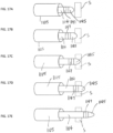
- FIG. 3A, FIG. 3B, FIG. 3C, FIG. 3D and FIG. 3E show an example of a procedure where a needle instrument (290) is used to form an opening (O) through an atrial septum (S); and a dilator (280) is used to enlarge the opening (O).
- a needle instrument 290
- a dilator 280
- the procedure begins with a sheath (270) that is positioned within the right atrium, such that an open distal end (272) of sheath (270) is oriented toward a penetration target location of the septum (S).
- sheath (270) may include a universal guiding sheath such as guiding sheath (200) described above; or may be a sheath that is configured specifically for use with dilator (280) and needle instrument (290) (e.g., as part of a kit, etc.).
- dilator (280) is advanced distally relative to sheath (270), such that dilator (280) protrudes distally from distal end (272) of sheath (270) as shown in FIG. 3B .
- Dilator (280) of this example has an open distal end (282) and a tapered outer surface (284) that narrows toward distal end (282).
- tapered outer surface (284) has a linear taper.
- tapered outer surface (284) has a curved taper.
- tapered outer surface (284) may have any other suitable configuration.
- needle instrument (290) is advanced distally relative to dilator (280), such that a distal shaft (292) of needle instrument (290) protrudes distally from distal end (282) of dilator (280) as shown in FIG. 3C .
- a distal tip (294) and a portion of distal shaft (262) of needle instrument (290) penetrate the septum (S), thereby forming an opening (O).
- distal tip (294) has a blunt configuration.
- distal tip (294) may have a dome shape or any other suitable configuration.
- Distal tip (294) of the present example further includes an electrode (296), which is activated to apply electrical energy (e.g., radiofrequency (AC type) or pulsed field (DC type) energy) to the tissue of the septum (S), to thereby assist in penetration of the septum (S). While one electrode (296) is shown, distal tip (294) may alternatively include two or more electrodes (296).
- electrical energy e.g., radiofrequency (AC type) or pulsed field (DC type) energy
- dilator (280) is advanced distally into the opening (O) as shown in FIG. 3D .
- needle instrument (290) is retracted proximally back into dilator (280) before dilator (280) is advanced distally into the opening (0).
- needle instrument (290) remains distally advanced relative to dilator (280) when dilator (280) is advanced distally into the opening (0).
- sheath (270) is advanced distally with dilator (280) when dilator (280) is advanced distally into the opening (0).
- sheath (270) remains stationary while dilator (280) is advanced distally into the opening (O). Regardless of the relative positioning of sheath (270) and needle instrument (290) when dilator (280) is advanced distally into the opening (0), tapered outer surface (284) of dilator (280) bears against the inner edge of the opening (O), thereby dilating the opening (O).
- dilator (280) Once dilator (280) has sufficiently dilated the opening (O), dilator (280) is retracted proximally relative to the opening (O), such that dilator (280) exits the dilated opening (O), as shown in FIG. 3E .
- sheath (270) is retracted proximally with dilator (280).
- dilator (280) and needle instrument (290) are completely removed from sheath (270) after reaching the state shown in FIG. 3E , while sheath (270) remains disposed in the right atrium.
- an additional instrument e.g., cardiac mapping catheter, cardiac ablation catheter, etc.
- sheath (2 70) may be removed from the right atrium and another sheath (e.g., guiding sheath (200)) is introduced into the right atrium; with additional instrumentation (e.g., cardiac mapping catheter, cardiac ablation catheter, etc.) being advanced through that other sheath to ultimately pass through the dilated opening (O).
- additional instrumentation e.g., cardiac mapping catheter, cardiac ablation catheter, etc.
- the end effector of catheter assembly (100) may be advanced from the right atrium through the dilated opening (O) to thereby position the end effector of catheter assembly (100) in the left atrium, in a pulmonary vein, and/or in any other suitable anatomical region on that side of the septum (S).
- sheath (270), or hollow shaft (220) of guiding sheath (200) is passed through the dilated opening (O) to further assist in guiding the end effector of catheter assembly (100) into the left atrium, into a pulmonary vein, and/or into any other suitable anatomical region on that side of the septum (S).
- the opening (O) may be closed using any suitable techniques.
- needle instrument (290) may be configured and operable in accordance with at least some of the teachings of U.S. Pat. No 6,994,094 ; U.S. Pat. No 8,152,829 ; U.S. Pat. No 9,848,943 ; U.S. Pub. No 2004/0220471 ; and/or U.S. Pub. No 2004/0220461 .
- the disclosures of each of these references is incorporated by reference herein, in its entirety.
- Some dilators (280) and/or needle instruments (290) may also include one or more pull-wires and/or other features that provide steerability to the distal end of dilator (280) and/or needle instrument (290).
- Some such versions may thus provide an additional degree of steerability after distal end (280) of dilator (280) and/or distal tip (2 of the instrument exits open distal end (240) of hollow shaft (220).
- Some transseptal needle instruments may also include a wire at tip (264), to assist in providing primary engagement and lead-in for tip (264) into the atrial septum (S).
- a transseptal puncture apparatus outfitted with an energized tip may alternatively take other forms.
- features of a needle as described herein may be applied to a guidewire; and features of a guidewire as described herein may be applied to a needle.
- the differences in construction between a guidewire or needle will pertain primarily to the materials and construction of the shaft, with the choice between guidewire versus needle for transseptal access being primarily a function of physician preference.
- a "transseptal puncture apparatus" or “transseptal apparatus” means either a guidewire or a needle having the tip features described herein within the scope of appended claims.
- the opening (O) through the atrial septum (S) via application of electrical energy (e.g., RF or IRE, etc.) to the tissue of the septum (S), such as to form the opening (O) without using a needle having a sharp distal tip and thereby eliminate the risk of such a sharp distal tip undesirably engaging with a wall or other structure of the heart (H) that is past the atrial septum (S) due to inadvertent over-advancement of the needle.
- electrical energy may include radiofrequency (AC type) electrical energy, pulsed field (DC type) electrical energy (e.g., irreversible electroporation, etc.), or some other form of electrical energy.
- transseptal puncture instruments (300), dilators (302, 402, 502, 602, 702, 802), and guidewires (304, 904, 1004) described below may function in such a manner.
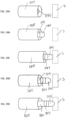
- FIG. 4A, FIG. 4B and FIG. 4C show a distal portion of an example of an instrument (300) that may be used to deliver electrical energy to tissue of an atrial septum (S) to form an opening (O) therethrough and that may also be used to dilate the opening (O).
- Instrument (300) of this example includes a dilator (302) and a guidewire (304) slidably housed within dilator (302) such that guidewire (304) and dilator (302) are extendable and retractable relative to each other.
- guidewire (304) may be extendable and retractable relative to dilator (302) between a proximal position ( FIG. 4A ) and a distal position ( FIG. 4B ).
- instrument (300) may include a handle assembly (not shown), which may be similar to handle assembly (110).
- the handle assembly may include any suitable actuation features for driving translation of dilator (302) and/or guidewire (304) relative to each other and/or relative to a handle body of the handle assembly, including but not limited to a slider, a pivoting rocker, a dial, etc.
- Instrument (300) may be coupled with an electrical generator (306), which may be operable to generate electrosurgical energy (e.g., RF or pulsed high-voltage DC, etc.) for delivery to the tissue of the septum (S) via instrument (300) to form the opening (O), as described in greater detail below.
- electrosurgical energy e.g., RF or pulsed high-voltage DC, etc.
- Dilator (302) of this example includes a shaft (310) defining a lumen (312) that is configured to slidably receive guidewire (304) and that extends distally to a distal end (314) of shaft (310).
- Shaft (310) is sized for insertion through insertion port (250) and hollow shaft (220) of guiding sheath (200). Guiding sheath (200) may thus be used to assist in positioning a dilator tip member (320) of dilator (302) in relation to a target puncture location of the septum (S) in a manner generally similar to that described above with reference to FIG. 3A .
- Shaft (310) may comprise a metallic material, a plastic material, and/or any other suitable kind(s) of material(s).
- Shaft (310) of the present example includes a generally annular distal receptacle (321) extending radially inwardly from a radially outer surface of shaft (310) and proximally from distal end (314) for facilitating coupling of dilator tip member (320) to shaft (310), as described in greater detail below.
- Dilator tip member (320) of the present example includes a body (322) having an open distal tip (324) and a proximal socket (326).
- Body (322) of the present example has a dome shape, such that distal tip (324) is atraumatic. More particularly, body (322) includes an exterior dilation surface (327) which curves radially inwardly toward distal tip (324) to define the illustrated dome shape. In some other versions, distal tip (324) may have any other suitable atraumatic configuration. In addition, or alternatively, dilation surface (327) may have any other suitable distally narrowing configuration. For example, dilation surface (327) may taper radially inwardly toward distal tip (324) to define a frustoconical shape (not shown).
- Proximal socket (326) of dilator tip member (320) receives distal end (314) of shaft (310) and is fixedly secured to shaft (310) such that a proximal portion of dilator tip member (320) is received within receptacle (321) of shaft (310).
- dilator tip member (320) may be welded to shaft (310), soldered to shaft (310), adhered to shaft (310) using an adhesive or epoxy, press-fit onto shaft (310), and/or fixedly secured to shaft (310) in any other suitable fashion.
- shaft (310) may include an exterior dilation surface (not shown) which narrows (e.g., curves or tapers radially inwardly) toward distal end (314) to provide a smooth transition from such an exterior dilation surface of shaft (310) to exterior dilation surface (327) of dilator tip member (320).
- Body (322) of dilator tip member (320) further defines a lumen (328) that is coaxial with lumen (312) of shaft (310) and that is configured to slidably receive guidewire (304).
- lumen (328) provides a pathway for guidewire (304) that is distally advanced through lumen (312) to protrude distally from distal end (314) of shaft (310) or otherwise be exposed relative to distal end (314) of shaft (310). This enables guidewire (304) to reach the tissue of the septum (S).
- lumen (328) has a diameter that is sufficiently larger than the diameter of tip member (350) of guidewire (304), to prevent inadvertent contact between tip member (350) and the sidewall of lumen (328). This may prevent short circuiting between tip member (320) and tip member (350), as will be understood in view of the description below.
- Dilator tip member (320) of the present example is formed of an electrically conductive material.
- dilator tip member (320) may be formed of any suitable material or combination of materials including but not limited to metallic conductive materials such as copper, gold, steel, aluminum, silver, nitinol, etc. and/or non-metallic conductive materials such as conducting polymers, silicides, graphite, etc.
- dilator tip member (320) is coupled with electrical generator (306) via at least one first electrically conductive wire (330) extending along shaft (310) to electrically couple dilator tip member (320) with electrical generator (306).
- first wire (330) may extend along shaft (310) in another lumen (not shown) that is isolated from lumen (312) to prevent first wire (330) from interfering with passage of guidewire (304) therethrough.
- dilator tip member (320) may be electrically coupled with electrical generator (306) via any other suitable electrically conductive element(s), such as via one or more electrically conductive traces (e.g., of a flex circuit, etc.) extending along shaft (310) or one or more other electrical conductors embedded directly into shaft (310). Dilator tip member (320) is thus operable to apply electrical energy to the tissue of the septum (S) to form the opening (O) as described in greater detail below.
- dilator tip member (320) is formed of a metallic material
- the dilator tip member (320) may serve as a single, monopolar electrode, such that a ground pad may contact the patient (PA) to provide a return path for the electrical energy, whether RF and/or pulsed DC or otherwise.
- shaft (310) is formed of an electrically conductive material
- an electrically insulating material may be interposed between dilator tip member (320) and shaft (310).
- dilator tip member (320) may include one or more electrically conductive elements secured to distal tip (324), with such electrically conductive elements serving as electrodes that are configured to deliver electrical energy to the tissue of the septum (S) (e.g., with an electrically insulating material being interposed between the conductive element(s) and body (322)).
- electrically conductive elements e.g., a pair of arcuate conductive elements may be angularly spaced apart from each other on distal tip (324) of dilator tip member (320).
- Such conductive element(s) may each include any one or more of a conductive wire, plate, film, and/or coating, and may be formed of any suitable material or combination of materials including but not limited to metallic conductive materials such as copper, gold, steel, aluminum, silver, nitinol, etc. and/or non-metallic conductive materials such as conducting polymers, silicides, graphite, etc.
- Such conductive element(s) may be secured to distal tip (324) in any suitable fashion, including but not limited to being secured via an adhesive, via vapor deposition, or otherwise, and may be electrically coupled with electrical generator (306) via first wire (330) extending along shaft (310).
- a corresponding pair of wires (330) may extend along shaft (310), and the pair of conductive elements may thereby be operable to apply bipolar electrical energy (e.g., RF or IRE) to the tissue of the septum (S), with one conductive element serving as an active electrode and the other conductive element serving as a return electrode to ablate the tissue, for example.
- bipolar electrical energy e.g., RF or IRE
- such conductive element(s) are configured and operable in accordance with at least some of the teachings of U.S. Pat. App. No. 17/557,256, entitled "ENT Instrument with Deformable Guide having Translatable Imaging Feature,” filed December 21, 2021 , the disclosure of which is incorporated by reference herein, in its entirety.
- dilator (302) includes at least one navigation sensor assembly (332) fixedly secured to shaft (310) that is operable to generate signals that are indicative of the position and orientation of shaft (310) and/or dilator tip member (320) within the patient (PA).
- Navigation sensor assembly (332) includes at least one electromagnetic coil (334) operable to generate signals indicative of the position of the respective coil (334) and thereby indicative of the position of a portion of shaft (310) in three-dimensional space when positioned within an alternating electromagnetic field generated by field generators (20).
- the position data generated by such position related signals may be processed by the processor of console (12) for providing a visual indication to the operator to show the operator where shaft (310) and/or dilator tip member (320) of dilator (302) is located within the patient (P) in real time.
- a visual indication may be provided as an overlay on one or more preoperatively obtained images (e.g., CT scans) of the patient's anatomy.
- the position data generated by position related signals from navigation sensor assembly (332) may be processed by the processor of console (12) to generate a current-to-position mapping (CPM) matrix.
- CPM current-to-position mapping
- such a CPM matrix may be generated in accordance with at least some of the teachings of U.S. Pat. No. 10,398,347, entitled “Sheath Visualization Method by Means of Impedance Localization and Magnetic Information,” issued September 3, 2019 , the disclosure of which is incorporated by reference herein, in its entirety; and/or U.S. Pat. No. 8,478,383, entitled “Probe Tracking Using Multiple Tracking Methods,” issued July 2, 2013 , the disclosure of which is incorporated by reference herein, in its entirety.
- Navigation sensor assembly (332) may be configured as a single-axis sensor (SAS) (e.g., having a single electromagnetic coil (334) wound about a single axis), as a dual-axis sensor (DAS) (e.g., having two electromagnetic coils (334) wound about respective axes), or as a triple-axis sensor (TAS) (e.g., having three electromagnetic coils (334) wound about respective axes).
- SAS single-axis sensor
- DAS dual-axis sensor
- TAS triple-axis sensor
- navigation sensor assembly (332) may be configured as a flexible printed circuit board (PCB).
- PCB flexible printed circuit board
- navigation sensor assembly (332) may be configured and operable in accordance with at least some of the teachings of U.S. Pat. App. No.
- navigation sensor assembly (332) may include one or more active current location (ACL) electrodes in addition to or in lieu of the aforementioned electromagnetic coil sensors.
- ACL active current location
- navigation sensor assembly (332) of the example shown is fixedly secured to an exterior surface of shaft (310), it will be appreciated that navigation sensor assembly (332) may be fixedly secured to any suitable portion of shaft (310).
- navigation sensor assembly (332) may be housed within shaft (310), such as disposed within lumen (312) while permitting passage of guidewire (304) therethrough.
- navigation sensor assembly (332) is configured to be coupled with guidance and drive system (10) via at least one second electrically conductive wire (336) extending along shaft (310) to electrically couple navigation sensor assembly (332) with guidance and drive system (10).
- second wire (336) may extend along shaft (310) in another lumen (not shown) that is isolated from lumen (312) to prevent second wire (336) from interfering with passage of guidewire (304) therethrough.
- navigation sensor assembly (332) may be electrically coupled with guidance and drive system (10) via any other suitable electrically conductive element(s), such as via one or more electrically conductive traces (e.g., of a flex circuit, etc.) extending along shaft (310) or one or more other electrical conductors embedded directly into shaft (310). In some cases, navigation sensor assembly (332) may be omitted. In some such cases, at least a distal portion of dilator (302) (e.g., including dilator tip member (320)) may be echogenic to facilitate visualization of at least the distal portion of dilator (302) via ultrasound.
- dilator (302) e.g., including dilator tip member (320)
- Guidewire (304) of this example includes an elongate member (340) extending to a distal end (344).
- Elongate member (340) may include a shaft or a coil, for example. In cases where elongate member (340) includes a coil, the coil may be wrapped about a core wire (not shown), which may be secured relative to distal end (344) and prevent the coil from elongating when the coil is placed under tensile stress.
- Elongate member (340) is sized for insertion through lumens (312, 328) of dilator (302). Dilator (302) may thus be used to assist in positioning a tip member (350) of guidewire (304) in relation to a target puncture location of the septum (S).
- Guidewire tip member (350) of the present example includes a body (352) having a distal tip (354).
- Distal tip (354) of the present example has a dome shape, such that distal tip (354) is atraumatic. In some other versions, distal tip (354) may have any other suitable atraumatic configuration.
- Guidewire tip member (350) is fixedly secured to elongate member (340) at or near distal end (344) of elongate member (340).
- body (352) may include a proximal socket (not shown) that receives distal end (344) of elongate member (340) and is fixedly secured to elongate member (340).
- Guidewire tip member (350) of the present example is formed of an electrically conductive material.
- guidewire tip member (350) may be formed of any suitable material or combination of materials including but not limited to metallic conductive materials such as copper, gold, steel, aluminum, silver, nitinol, etc. and/or non-metallic conductive materials such as conducting polymers, silicides, graphite, etc.
- Guidewire tip member (350) may be coupled with electrical generator (306) via one or more wires, traces (e.g., of a flex circuit, etc.), or other electrically conductive elements (not shown) extending along elongate member (340) to electrically couple guidewire tip member (350) with electrical generator (306).
- Guidewire tip member (350) is thus operable to apply electrical energy to the tissue of the septum (S) to form the opening (O) as described in greater detail below.
- the guidewire tip member (350) may serve as a single, monopolar electrode, such that a ground pad may contact the patient (PA) to provide a return path for the electrical energy.
- an electrically insulating material may be interposed between guidewire tip member (350) and elongate member (340).
- guidewire tip member (350) may include one or more electrically conductive elements secured to distal tip (354) and configured to deliver electrical energy to the tissue of the septum (S) (e.g., with an electrically insulating material being interposed between the conductive element(s) and body (352)).
- a pair of arcuate conductive elements may be angularly spaced apart from each other on distal tip (354) of guidewire tip member (350).
- Such conductive element(s) may each include any one or more of a conductive wire, plate, film, and/or coating, and may be formed of any suitable material or combination of materials including but not limited to metallic conductive materials such as copper, gold, steel, aluminum, silver, nitinol, etc.
- a corresponding pair of wires may extend along elongate member (340), and the pair of conductive elements may thereby be operable to apply bipolar electrical energy to the tissue of the septum (S), with one conductive element serving as an active electrode and the other conductive element serving as a return electrode to ablate the tissue, for example.
- such conductive element(s) are configured and operable in accordance with at least some of the teachings of U.S. Pub. No. 2022/0110513, entitled "ENT Instrument with Deformable Guide having Translatable Imaging Feature," published April 14, 2022 , the disclosure of which is incorporated by reference herein, in its entirety.
- guidewire tip member (350) may cooperate with dilator tip member (320) to provide bipolar electrical energy as described below.
- guidewire (304) may be configured and operable in accordance with at least some of the teachings of U.S. Pat. No. 11,213,344, entitled “Guidewire with Ablation and Coagulation Functionality,” issued January 4, 2022 , the disclosure of which is incorporated by reference herein, in its entirety; U.S. Pat. No. 10,603,472, entitled “Guidewires Having Improved Mechanical Strength and Electromagnetic Shielding,” issued March 31, 2020 , the disclosure of which is incorporated by reference herein, in its entirety; and/or U.S. Pub. No. 2021/0196370, entitled “Neurosurgery Guidewire with Integral Connector for Sensing and Applying Therapeutic Electrical Energy,” published July 1, 2021 , the disclosure of which is incorporated by reference herein, in its entirety.
- guidewire (304) includes at least one navigation sensor assembly (not shown) fixedly secured to elongate member (340) that is operable to generate signals (e.g., in response to the presence of an alternating electromagnetic field generated by field generators (20)) that are indicative of the position and orientation of elongate member (340) and/or guidewire tip member (350) within the patient (PA), such as in a manner similar to that described above.
- navigation sensor assembly fixedly secured to elongate member (340) that is operable to generate signals (e.g., in response to the presence of an alternating electromagnetic field generated by field generators (20)) that are indicative of the position and orientation of elongate member (340) and/or guidewire tip member (350) within the patient (PA), such as in a manner similar to that described above.
- dilator tip member (320) (or the conductive element(s) thereof) and guidewire tip member (350) (or the conductive element(s) thereof) are configured to cooperate with each other to apply bipolar electrical energy to the tissue of the septum (S).
- guidewire tip member (350) (or the conductive element(s) thereof) may serve as an active electrode while dilator tip member (320) (or the conductive element(s) thereof) serves as a return electrode.
- dilator tip member (320) (or the conductive element(s) thereof) may serve as an active electrode while guidewire tip member (350) (or the conductive element(s) thereof) serves as a return electrode.
- such application of bipolar electrical energy to the tissue of the septum (S) may be sufficient to form the opening (O) therethrough.
- bipolar electrical energy for forming the opening (O) may be performed with relatively low power, at least by comparison to application of monopolar electrical energy via either dilator tip member (320) or guidewire tip member (350) for forming the opening (O).
- lumen (328) of tip member (320) has a diameter that is sufficiently larger than the diameter of tip member (350) of guidewire (304), to prevent inadvertent contact between tip member (350) and the sidewall of lumen (328). This may prevent short circuiting between tip member (320) and tip member (350), particularly when one or both of tip members (320, 350) is/are activated to apply electrical energy.
- dilator (302) may initially be inserted through guiding sheath (200) to engage dilator tip member (320) (or the conductive element(s) thereof) with the tissue at the target puncture location of the septum (S), while guidewire (304) may be in a retracted position relative to dilator (302), as shown in FIG. 4A .
- the physician (PH) may advance guidewire (304) distally through dilator (302) to engage guidewire tip member (350) (or the conductive element(s) thereof) with the tissue at the target puncture location of the septum (S) and may subsequently activate generator (306), with dilator tip member (320) (or the conductive element(s) thereof) and guidewire tip member (350) (or the conductive element(s) thereof) serving as electrodes applying bipolar electrical energy to the tissue at the target puncture location of the septum (S) to form the opening (O) therethrough, as shown in FIG. 4B .
- dilator tip member (320) (or the conductive element(s) thereof) and guidewire tip member (350) (or the conductive element(s) thereof) may be accurately positioned relative to the tissue at the target puncture location of the septum (S) based on the position data generated by the position related signals received from navigation sensor assembly (332) of dilator (302) and/or the navigation sensor assembly of guidewire (304).
- dilator (302) and guidewire (304) may include complementary (e.g., interlocking) mechanical features for facilitating rotational and/or longitudinal positioning of dilator tip member (320) (or the conductive element(s) thereof) and guidewire tip member (350) (or the conductive element(s) thereof) relative to each other a predetermined manner for achieving the desired delivery of bipolar electrical energy.
- dilator (302) and guidewire (304) may be configured to threadably engage each other to provide such predetermined relative positioning.
- dilator (302) and guidewire (304) may include corresponding indicia configured to align with each other to visually indicate such predetermined relative positioning; detent features to provide tactile feedback indicating appropriate relative positioning; and/or any other suitable features indicating appropriate relative positioning.
- the processor of console (12) may read cardiac electrical (e.g., EGMs, impedance change, etc.) signals from dilator tip member (320) (or the conductive element(s) thereof) and guidewire tip member (350) (or the conductive element(s) thereof) to confirm that dilator tip member (320) (or the conductive element(s) thereof) and guidewire tip member (350) (or the conductive element(s) thereof) are both sufficiently engaged with the tissue at the target puncture location of the septum (S) for the tissue to receive the bipolar electrical energy prior to activation of electrical generator (306).
- cardiac electrical e.g., EGMs, impedance change, etc.
- activation and/or deactivation of electrical generator (306) may be performed automatically by the processor of console (12), such as in response to feedback received by the processor of console (12) from dilator tip member (320) (or the conductive element(s) thereof) and guidewire tip member (350) (or the conductive element(s) thereof) to ensure proper ablation of the desired target tissue.
- activation may be performed manually by the physician (PH), such as based on images or other information presented by display (18).
- the electrical impedance between dilator tip member (320) (or the conductive element(s) thereof) and guidewire tip member (350) (or the conductive element(s) thereof) may be periodically or continuously measured during the application of bipolar electrical energy the tissue at the target puncture location of the septum (S) to monitor the progress of the formation of the opening (O).
- the impedance may be relatively high during ablation of the tissue at the target puncture location of the septum (S) as a result of tissue vaporization between dilator tip member (320) (or the conductive element(s) thereof) and guidewire tip member (350) (or the conductive element(s) thereof), and may substantially decrease upon the formation of the opening (O) when guidewire tip member (350) (or the conductive element(s) thereof) is no longer contacting and vaporizing through septal tissue. This substantial decrease in the impedance may thus provide an indication that the opening (O) has been successfully formed.
- the processor of console (12) may automatically deactivate electrical generator (306) in response to the substantial decrease in the impedance, thereby preventing the risk of ablating a wall or other structure of the heart (H) that is past the atrial septum (S).
- display (18) may alert the physician (PH) that the opening (O) has been formed so that the physician (PH) may take appropriate action.
- the application of bipolar electrical energy to the tissue at the target puncture location of the septum (S) may be performed while maintaining each of dilator tip member (320) and guidewire tip member (350) at substantially fixed locations relative to the target puncture location of the septum (S) or while urging dilator tip member (320) and/or guidewire tip member (350) only slightly distally (e.g., to maintain electrical contact with the tissue at the target puncture location of the septum (S)), such that the opening (O) may be formed without applying any mechanical force, or while applying only nominal mechanical force, against the tissue at the target puncture location of the septum (S).
- either no or only minimal mechanical force may be required to form the opening (O), thereby eliminating or mitigating the risk of inadvertently over-advancing instrument (300), at least during the initial formation of the opening (O).
- the atraumatic configurations of distal tip (324) and distal tip (354) may prevent injury to a wall or other structure of the heart (H) that is past the atrial septum (S) if such inadvertent over-advancement of dilator (302) and/or guidewire (304) occurs.
- a determination that the opening (O) has been successfully formed may be based on the position data generated by the position related signals received from navigation sensor assembly (332) of dilator (302) and/or the navigation sensor assembly of guidewire (304), in addition to or in lieu of the aforementioned impedance-based determination.
- the physician (PH) may in some cases advance dilator (302) distally through the opening (O) following the initial formation of the opening (O) to engage dilation surface (327) of dilator tip member (320) (and/or a dilation surface of shaft (310)) with the periphery of the opening (O) and thereby expand the opening (O).
- the physician (PH) may advance dilator (302) and/or guidewire (304) through the opening (O) to perform additional operations beyond the septum (S).
- the physician (PH) may advance dilator (302) and/or guidewire (304) through the opening (O) to reach the left atrium of the heart (H) to provide EP mapping, ablation, or any other kind of additional operations in the left atrium.
- dilator (302) and/or guidewire (304) may allow the additional operation(s) to be performed immediately following the formation of the opening (O) without first requiring an instrument exchange; and may thereby reduce the risk of air being aspirated into the heart (H) of the patient (PA) and/or reduce the duration of the procedure.
- guidewire (304) may be advanced through the opening (O) immediately upon formation of the opening (O) to position guidewire tip member (350) within the left atrium to enable a CPM matrix to be generated for the left atrium (e.g., based on the position data generated by the position related signals received from the navigation sensor assembly of guidewire (304)).
- guidewire tip member (350) may serve as an anchor in the left atrium such that one or more additional instruments (e.g., catheter of catheter assembly (100), etc.) may be advanced distally over guidewire (304), through the opening (O), and into the left atrium.
- guidewire (304) may be inserted into a major vein or artery (e.g., the femoral artery) of the patient (PA) (e.g., via the leg or groin of the patient (PA)) and then advanced distally along the vein or artery to position guidewire tip member (350) within the right atrium of the heart (H) to serve as an anchor therein. Guiding sheath (200) may then be advanced distally along the vein or artery over guidewire (304) for facilitating the subsequent insertion of dilator (302) through guiding sheath (200) to the position shown in FIG. 4A .
- a major vein or artery e.g., the femoral artery
- guidewire tip member e.g., the right atrium of the heart (H)
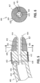
- FIG. 5 and FIG. 6 show a distal portion of another example of a dilator (402) having such a configuration, and which may be incorporated into instrument (300) in place of dilator (302).
- Dilator (402) may be similar to dilator (302) described above except as otherwise described below.
- dilator (402) of this example includes a shaft (410) defining a lumen (412) that is configured to slidably receive guidewire (304) and that extends distally to a distal end (414) of shaft (410).
- Shaft (410) is sized for insertion through insertion port (250) and hollow shaft (220) of guiding sheath (200).
- Guiding sheath (200) may thus be used to assist in positioning a dilator tip member (420) of dilator (402) in relation to a target puncture location of the septum (S) in a manner generally similar to that described above with reference to FIG. 3A .
- Shaft (410) of the present example includes a generally annular distal receptacle (421) extending radially inwardly from a radially outer surface of shaft (410) and proximally from distal end (414) for facilitating coupling of dilator tip member (420) to shaft (410).
- dilator tip member (420) of the present example includes a body (422) having an open distal tip (424) and a longitudinal bore (426).
- Body (422) may be formed of an electrically conductive material, such that tip member (420) may serve as a monopolar electrode or as a bipolar electrode as described herein.
- Body (422) of the present example has a dome shape, such that distal tip (424) is atraumatic. More particularly, body (422) includes an exterior dilation surface (427) which curves radially inwardly toward distal tip (424) to define the illustrated dome shape. Dilator tip member (420) is received within receptacle (421) of shaft (410).
- Dilator tip member (420) and, more particularly, bore (426), may have a length substantially equal to that of receptacle (421) of shaft (410) such that the portion of shaft (410) that is radially inward of receptacle (421) may be interposed between dilator tip member (420) and guidewire tip member (350) along substantially the entire length thereof to thereby inhibit electrical shorting between dilator tip member (420) and guidewire tip member (350) during electrical energization of dilator tip member (420) and guidewire tip member (350).
- dilator tip member (420) may be coupled with electrical generator (306) via one or more wires, traces, or other electrically conductive elements (not shown) extending along shaft (410) to electrically couple dilator tip member (420) with electrical generator (306) in a manner similar to that described above in connection with FIG. 4A, FIG 4B and FIG. 4C .
- dilator (402) includes at least one navigation sensor assembly (432) fixedly secured to shaft (410) that is operable to generate signals that are indicative of the position and orientation of shaft (410) and/or dilator tip member (420) within the patient (PA).
- Navigation sensor assembly (432) includes at least one electromagnetic coil (434) operable to generate signals indicative of the position of the respective coil (434) and thereby indicative of the position of a portion of shaft (410) in three-dimensional space when positioned within an alternating electromagnetic field generated by field generators (20), in a manner similar to that described above.
- navigation sensor assembly (432) is configured to be coupled with guidance and drive system (10) via at least one electrically conductive wire (436) extending along shaft (410) to electrically couple navigation sensor assembly (432) with guidance and drive system (10).
- navigation sensor assembly (432) may be coupled with guidance and drive system (10) in any other suitable fashion.
- navigation sensor assembly (432) may be positioned at any other suitable location(s) in relation to shaft (410).
- FIG. 7 shows a distal portion of another example of a dilator (502) having such a configuration, and which may be incorporated into instrument (300) in place of dilator (302).
- Dilator (502) may be similar to dilator (302) described above except as otherwise described below.
- dilator (502) of this example includes a shaft (510) defining a lumen (512) that is configured to slidably receive guidewire (304) and that extends distally to a distal end (514) of shaft (510).
- Shaft (510) is sized for insertion through insertion port (250) and hollow shaft (220) of guiding sheath (200).
- Guiding sheath (200) may thus be used to assist in positioning a pair of dilator tip members (520a, 520b) of dilator (402) in relation to a target puncture location of the septum (S) in a manner generally similar to that described above with reference to FIG. 3A .
- Shaft (510) of the present example includes a generally semi-annular distal receptacle (521) extending radially inwardly from a radially outer surface of shaft (510) and proximally from distal end (514) for facilitating coupling of first dilator tip member (520a) to shaft (510), while second dilator tip member (520a) may be integrally formed together with shaft (510) as a unitary (e.g., monolithic) piece.
- Each dilator tip member (520a, 520b) of the present example includes a body (522a, 522b).
- First body (522a) may be formed of an electrically conductive material, such that first dilator tip member (520a) may serve as a monopolar electrode or as a bipolar electrode as described herein.
- Each body (522a, 522b) is fixedly secured to distal end (514) of shaft (510) on respective sides of lumen (512) to collectively define an open distal tip (524) and a lumen (528) that is coaxial with lumen (512) of shaft (510).
- Lumen (528) is configured to slidably receive guidewire (304).
- Bodies (522a, 522b) of the present example collectively define a dome shape, such that distal tip (524) is atraumatic. More particularly, each body (522a, 522b) includes an exterior dilation surface (527a, 527b) which curves radially inwardly toward distal tip (524) to define the illustrated dome shape.
- Body (522a) of first dilator tip member (520a) has a proximal socket (526) which receives distal end (514) of shaft (510) and is fixedly secured to shaft (510) such that a proximal portion of first dilator tip member (520a) is received within receptacle (521) of shaft (510).
- First dilator tip member (520a) may be coupled with electrical generator (306) via one or more wires, traces, or other electrically conductive elements (not shown) extending along shaft (510) to electrically couple first dilator tip member (520a) with electrical generator (306) in a manner similar to that described above in connection with FIG. 4A, FIG. 4B and FIG. 4C , and may thereby be operable to cooperate with guidewire tip member (350) to apply bipolar electrical energy to the tissue of the septum (S) on one side of lumen (528); while second dilator tip member (520b) remains unenergized such that electrical energy is not applied to the tissue of the septum (S) on the other side of lumen (528).
- dilator (502) includes at least one navigation sensor assembly (532) fixedly secured to shaft (510) that is operable to generate signals that are indicative of the position and orientation of shaft (510) and/or dilator tip members (520a, 520b) within the patient (PA).
- Navigation sensor assembly (532) includes at least one electromagnetic coil (534) operable to generate signals indicative of the position of the respective coil (534) and thereby indicative of the position of a portion of shaft (510) in three-dimensional space when positioned within an alternating electromagnetic field generated by field generators (20), in a manner similar to that described above.
- navigation sensor assembly (532) is configured to be coupled with guidance and drive system (10) via at least one electrically conductive wire (536) extending along shaft (510) to electrically couple navigation sensor assembly (532) with guidance and drive system (10).
- navigation sensor assembly (532) may be coupled with guidance and drive system (10) in any other suitable fashion.
- navigation sensor assembly (532) may be positioned at any other suitable location(s) in relation to shaft (510).
- FIG. 8 and FIG. 9 show a distal portion of another example of a dilator (602) having such a configuration, and which may be incorporated into instrument (300) in place of dilator (302).
- Dilator (602) may be similar to dilator (302) described above except as otherwise described below.
- dilator (602) of this example includes a shaft (610) defining a lumen (612) that is configured to slidably receive guidewire (304) and that extends distally to a distal end (614) of shaft (610).
- Shaft (610) is sized for insertion through insertion port (250) and hollow shaft (220) of guiding sheath (200). Guiding sheath (200) may thus be used to assist in positioning a pair of dilator tip members (620a, 620b) of dilator (602) in relation to a target puncture location of the septum (S) in a manner generally similar to that described above with reference to FIG. 3A .
- Each dilator tip member (620a, 620b) of the present example includes a body (622a, 622b).
- Each body (622a, 622b) may be formed of an electrically conductive material, such that each dilator tip member (620a, 620b) may serve as a monopolar electrode or as a bipolar electrode as described herein.
- Each body (622a, 622b) is fixedly secured to distal end (614) of shaft (610) on respective sides of lumen (612) to collectively define an open distal tip (624) and a lumen (628) that is coaxial with lumen (612) of shaft (610) and that is configured to slidably receive guidewire (304).
- Bodies (622a, 622b) of the present example collectively define a dome shape, such that distal tip (624) is atraumatic. More particularly, each body (622a, 622b) includes an exterior dilation surface (627a, 627b) which curves radially inwardly toward distal tip (624) to define the illustrated dome shape. As best shown in FIG. 9 , bodies (622a, 622b) collectively have a circular cross-sectional shape that is coaxial with lumen (612) of shaft (610), such that bodies (622a, 622b) may collectively circumferentially surround a longitudinal axis of lumen (612).
- Dilator tip members (620a, 620b) may each be electrically coupled with electrical generator (306) via respective wires (not shown) extending along shaft (610), such that dilator tip members (620a, 620b) may thereby be operable to apply bipolar electrical energy to the tissue of the septum (S), with one dilator tip member (620a, 620b) serving as an active electrode and the other dilator tip member (620a, 620b) serving as a return electrode to ablate the tissue, for example.
- dilator (602) may be capable of forming the opening (O) independently of guidewire (304), such that guidewire tip member (350) may be omitted.
- the ability of dilator (602) to form the opening (O) independently of guidewire (304) may allow lumen (612) to be closed at or near distal end (614) of shaft (610) such that lumen (612) may facilitate routing of wires along shaft (610) to dilator tip members (620a, 620b), for example; but may not provide a pathway for guidewire (304) to be distally advanced out through distal end (614) of shaft (610) or otherwise enable guidewire (304) to reach the tissue of the septum (S).
- the ability of dilator (602) to form the opening (O) independently of guidewire (304) may allow lumen (612) to be omitted.
- dilator (602) may include a navigation sensor assembly like any other navigation sensor assembly described herein.
- FIG. 10 shows a distal portion of another example of a dilator (702) having such a configuration, and which may be incorporated into instrument (300) in place of dilator (302).
- Dilator (702) may be similar to dilator (602) described above except as otherwise described below.
- dilator (702) of this example includes a shaft (not shown) defining a lumen (712) that is configured to slidably receive guidewire (304) and that extends distally to a distal end (not shown) of the shaft. Lumen (712) is laterally offset from the central longitudinal axis of the shaft in this example. Dilator (702) further includes a pair of dilator tip members (720a, 720b).
- Each dilator tip member (720a, 720b) of the present example includes a body (722a, 722b).
- Each body (722a, 722b) may be formed of an electrically conductive material, such that each dilator tip member (720a, 720b) may serve as a monopolar electrode or as a bipolar electrode as described herein.
- Each body (722a, 722b) is fixedly secured to the distal end of the shaft on respective sides of lumen (712) to collectively define an open distal tip (not shown) and a lumen (728) that is coaxial with lumen (712) of the shaft and that is configured to slidably receive guidewire (304).
- Lumen (728) is thus also laterally offset from the central longitudinal axis of the shaft of dilator (702) in this example.
- Bodies (722a, 722b) of the present example may collectively have a dome shape, such that the distal tip is atraumatic. More particularly, each body (722a, 722b) includes an exterior dilation surface (727a, 727b) which may curve radially inwardly toward the distal tip to define such a dome shape.
- bodies (722a, 722b) collectively have a circular cross-sectional shape that is non-coaxial with lumen (712) of the shaft, such that bodies (722a, 722b) may not collectively circumferentially surround a longitudinal axis of lumen (712).
- a lateral side of lumen (728) may be exposed such that lumen (728) may be generally C-shaped, to thereby inhibit septal tissue coring during electrical energization of dilator tip members (720a, 720b).
- dilator tip members (720a, 720b) may each be electrically coupled with electrical generator (306) via respective wires (not shown) extending along shaft (710) in a manner similar to that described above in connection with FIG. 8 and FIG. 9 .
- dilator (702) may include a navigation sensor assembly like any other navigation sensor assembly described herein.
- FIG. 11 and FIG. 12 show a distal portion of another example of a dilator (802) having such a configuration, and which may be incorporated into instrument (300) in place of dilator (302).
- Dilator (802) may be similar to dilator (602) described above except as otherwise described below.
- dilator (802) of this example includes a shaft (810) defining a lumen (812) that is configured to slidably receive guidewire (304) and that extends distally to a distal end (814) of shaft (810).
- Shaft (810) is sized for insertion through insertion port (250) and hollow shaft (220) of guiding sheath (200). Guiding sheath (200) may thus be used to assist in positioning a pair of dilator tip members (820a, 820b) of dilator (802) in relation to a target puncture location of the septum (S) in a manner generally similar to that described above with reference to FIG. 3A .
- Shaft (810) of the present example includes a first generally annular distal receptacle (821a) extending radially inwardly from a radially outer surface of shaft (810) and proximally from distal end (814) for facilitating coupling of first dilator tip member (820a) to shaft (810), and a second generally annular distal receptacle (821b) extending radially outwardly from lumen (812) and proximally from distal end (814) for facilitating coupling of second dilator tip member (820b) to shaft (810).
- each dilator tip member (820a, 820b) of the present example includes a body (822a, 822b).
- Each body (822a, 822b) may be formed of an electrically conductive material, such that each dilator tip member (820a, 820b) may serve as a monopolar electrode or as a bipolar electrode as described herein.
- Each body (822a, 822b) is fixedly secured to distal end (814) of shaft (810) at respective radial distances from lumen (612).
- Second dilator tip member (820b) is received within second receptacle (821b) of shaft (810), and defines an open, atraumatic distal tip (824) and a lumen (828) that is coaxial with lumen (812) of shaft (810) and that is configured to slidably receive guidewire (304).
- Body (822a) of first dilator tip member (820a) of the present example has a dome shape
- body (822b) of second dilator tip member (820b) has a cylindrical shape.
- body (822a) includes an exterior dilation surface (827) that curves radially inwardly toward distal tip (824) to define the illustrated dome shape.
- Body (822a) of first dilator tip member (820a) has a bore (826) and is received within first receptacle (821a) of shaft (810).
- bodies (822a, 822b) each have a circular cross-sectional shape and are coaxial with each other.
- Dilator tip members (820a, 820b) may each be electrically coupled with electrical generator (306) via respective wires (not shown) extending along shaft (810), such that dilator tip members (820a, 820b) may thereby be operable to apply bipolar electrical energy to the tissue of the septum (S), with one dilator tip member (820a, 820b) serving as an active electrode and the other dilator tip member (820a, 820b) serving as a return electrode to ablate the tissue, for example.
- dilator (802) may be capable of forming the opening (O) independently of guidewire (304).
- dilator (802) may include a navigation sensor assembly like any other navigation sensor assembly described herein.
- FIG. 13A, FIG. 13B, FIG. 13C and FIG. 13D show a distal portion of another example of a guidewire (904) having such a configuration, and which may be incorporated into instrument (300) in place of guidewire (304).
- Guidewire (904) may be similar to guidewire (304) described above except as otherwise described below.
- guidewire (904) of this example includes an elongate member (940) extending to a distal end (944).
- Elongate member (940) may include a shaft or a coil, for example.
- the coil may be wrapped about a core wire (not shown), which may be secured relative to distal end (944) and prevent the coil from elongating when the coil is placed under tensile stress.
- Elongate member (940) is sized for insertion through lumens (312, 328) of dilator (302). Dilator (302) may thus be used to assist in positioning a guidewire tip member (950) of guidewire (904) in relation to a target puncture location of the septum (S).
- Guidewire tip member (950) of the present example includes a body (952) having a distal tip (954).
- Body (952) may be formed of an electrically conductive material, such that guidewire tip member (950) may serve as a monopolar electrode or as a bipolar electrode as described herein.
- Distal tip (954) of the present example has a dome shape, such that distal tip (954) is atraumatic.
- Guidewire tip member (950) is fixedly secured to elongate member (940) at or near distal end (944) of elongate member (940).
- body (952) may include a proximal socket (not shown) that receives distal end (944) of elongate member (940) and is fixedly secured to elongate member (940).
- Guidewire tip member (950) may be coupled with electrical generator (306) via one or more wires, traces, or other electrically conductive elements (not shown) extending along elongate member (940) to electrically couple guidewire tip member (950) with electrical generator (306) in a manner similar to that described above in connection with FIG. 4A, FIG. 4B and FIG. 4C ; and may thereby be operable to cooperate with dilator tip member (320) to apply bipolar electrical energy to the tissue of the septum (S).
- guidewire (904) includes a plurality of navigation sensor assemblies (962a, 962b) fixedly secured to elongate member (940) that are operable to generate signals that are indicative of the position and orientation of elongate member (940) and/or guidewire tip member (950) within the patient (PA). More particularly, guidewire (904) includes a plurality of (e.g., three) first navigation sensor assemblies (962a) and a plurality of (e.g., two) second navigation sensor assemblies (962b).
- First navigation sensor assemblies (962a) may each include at least one electromagnetic coil (not shown) operable to generate signals indicative of the position of the respective coil and thereby indicative of the position of a portion of elongate member (940) in three-dimensional space when positioned within an alternating electromagnetic field generated by field generators (20), in a manner similar to that described above.
- Second navigation sensor assemblies (962b) may each include one or more active current location (ACL) electrodes.
- first and second navigation sensor assemblies (962a, 962b) may be collectively configured as a flexible printed circuit board (PCB).
- PCB flexible printed circuit board
- navigation sensor assemblies (962a, 962b) may be configured and operable in accordance with at least some of the teachings of U.S. Pat. App. No.
- the distal portion of guidewire (904) is configured to assume a variety of poses.
- the distal portion of guidewire (904) may be configured to assume a generally straight pose ( FIG. 13A ), such as for facilitating advancement of the distal portion of guidewire (904) through lumens (312, 328) of dilator (302).
- the distal portion of guidewire (904) may also be configured to assume a generally J-shaped pose ( FIG. 13B ) in which the distal portion of guidewire (904) bends backwards such that distal tip (954) of guidewire tip member (950) faces proximally.
- the distal portion of guidewire (904) may be configured to assume a generally lasso-shaped pose ( FIG. 13C ) in which the distal portion of guidewire (904) spirals such that distal tip (954) of guidewire (904) faces distally.
- the distal portion of guidewire (904) may be configured to assume a generally undulating pose ( FIG. 13D ) in which the distal portion of guidewire (904) bends upwardly and downwardly in an alternating manner.
- the distal portion of guidewire (904) may be configured to transition from the straight pose shown in FIG. 13A to any one or more of the J-shaped pose shown in FIG. 13B , the lasso-shaped pose shown in FIG. 13C , or the undulating pose shown in FIG. 13D , in response to distal tip (954) of guidewire tip member (950) impacting a wall or other structure of the heart (H) that is past the atrial septum (S), such as due to inadvertent over-advancement of guidewire (904) through the opening (O).
- transitioning of guidewire (904) from the straight pose to any of the J-shaped pose, the lasso-shaped pose, or the undulating pose may further reduce the risk of distal tip (954) injuring the wall or other structure of the heart (H) that is past the atrial septum (S).
- transitioning of the distal portion of guidewire (904) may allow the distal portion of guidewire (904) to serve as an anchor in the left atrium such that one or more additional instruments (e.g., catheter of catheter assembly (100), etc.) may be advanced distally over guidewire (904), through the opening (O), and into the left atrium.
- the position data generated by position related signals received from navigation sensor assemblies (962a, 962b) may be processed by the processor of console (12) for determining whether the distal portion of guidewire (904) is in the straight, J-shaped, lasso-shaped, or undulating pose, for example, and/or for providing a visual indication to the operator to show the operator where the distal portion of guidewire (904) and/or guidewire tip member (950) is located within the patient (P) in real time.
- FIG. 14 shows a distal portion of another example of a guidewire (1004) having such a configuration, and which may be incorporated into instrument (300) in place of guidewire (304).
- Guidewire (1004) may be similar to guidewire (304) described above except as otherwise described below.
- guidewire (1004) of this example includes an elongate member (1040) extending to a distal end (not shown).
- Elongate member (1040) may include a shaft or a coil, for example.
- elongate member (1040) includes a coil
- the coil may be wrapped about a core wire (not shown), which may be secured relative to the distal end and prevent the coil from elongating when the coil is placed under tensile stress.
- Elongate member (1040) is sized for insertion through lumens (312, 328) of dilator (302).
- Dilator (302) may thus be used to assist in positioning a pair of guidewire tip members (1050a, 1050b) of guidewire (1004) in relation to a target puncture location of the septum (S).
- Guidewire tip members (1050a, 1050b) may be formed of an electrically conductive material, such that each guidewire tip member (1050a, 1050b) may serve as a monopolar electrode or as a bipolar electrode as described herein.
- each guidewire tip member (1050a, 1050b) of the present example includes a body (1052a, 1052b).
- Each body (1052a, 1052b) is fixedly secured to the distal end of elongate member (1040), such that a distal region of each body (1052a, 1052b) is exposed for contact with tissue.
- Second guidewire tip member (1050b) is received within an interior of elongate member (1040), while first guidewire tip member (1050a) is positioned about an exterior of elongate member (1040). As shown, bodies (1052a, 1052b) each have a circular cross-sectional shape that are coaxial with each other.
- Guidewire tip members (1050a, 1050b) may each be electrically coupled with electrical generator (306) via respective wires (not shown) extending along elongate member (1040), such that guidewire tip members (1050a, 1050b) may thereby be operable to apply bipolar electrical energy to the tissue of the septum (S), with one guidewire tip member (1050a, 1050b) serving as an active electrode and the other guidewire tip member (1050a, 1050b) serving as a return electrode to ablate the tissue, for example.
- guidewire (1004) may be capable of forming the opening (O) independently of dilator (302), such that dilator tip member (320) may be omitted.
- a needle instrument for example, a guidewire, having an electrically-conductive distal to ablate tissue with a nonablating electrode operable to provide impedance signals to determine (i) whether the distal end of needle instrument is inside the guiding sheath or outside exposed to blood, (ii) if the distal end of the needle instrument has crossed the septum tissue; and (iii) location and direction of needle instrument.
- a needle instrument for example, a guidewire, having an electrically-conductive distal to ablate tissue with a nonablating electrode operable to provide impedance signals to determine (i) whether the distal end of needle instrument is inside the guiding sheath or outside exposed to blood, (ii) if the distal end of the needle instrument has crossed the septum tissue; and (iii) location and direction of needle instrument.
- the needle instrument (1114) may be similar to guidewire (304) described above except as otherwise described below.
- the needle instrument (1114) of this example includes an elongate member (1140) with an electrically-conductive distal end or electrode (1145) operable to be electrically energized by the electrical generator (1180) for ablating septum tissue.
- Elongate member (1140) may include a shaft or a coil, for example.
- elongate member (1140) includes a coil
- the coil may be wrapped about a core wire (not shown), which may be secured relative to the distal end and prevent the coil from elongating when the coil is placed under tensile stress.
- Elongate member (1140) is sized for insertion through lumen (1138) of a lumened instrument, for example, the guiding sheath (1105).
- the sheath (1105) may thus be used to assist in positioning the distal end (1145) of the needle instrument (1114) in relation to a target puncture location of the septum (S).
- the distal electrode (1145) may be formed of an electrically conductive material, such that it may serve as a monopolar electrode or as a bipolar electrode as described herein.
- the distal electrode (1145) may be formed as a dome tip electrode or as a distal ring electrode, as known in the art. It is understood that while the instrument is referred to herein as a needle instrument the instrument has an atraumatic distal end, that is without any tissue-piercing distal end that has a sharp or pointed configuration. That is, without ablation, the needle instrument is not intended to pierce or puncture tissue merely due to its physical structure, and thus the distal end may be hemispherical, flat, domed or of any other suitable configuration or profile.
- the distal electrode (1145) is electrically connected to receive electrical energy from the electrical generator (1180) via at least an electrically conductive wire extending along elongate member (1140) or any other suitable electrically conductive element(s), such as via one or more electrically conductive traces (e.g., of a flex circuit, etc.) extending along elongate member (1140) or one or more other electrical conductors embedded directly into the elongate member (1140).
- Distal electrode (1145) is thus operable to apply electrical energy to the tissue of the septum (S) to form the opening (O) as described herein.
- the needle instrument (1114) advantageously includes a second electrode (1147) electrically insulated from the ablation distal electrode (1145).
- the needle instrument (1114) includes a proximal electrode (1147) proximal of the distal electrode (1145), for example, configured as a ring electrode.
- proximal electrode (1147) proximal of the distal electrode (1145
- at least a portion of elongate member (1140) spans between the distal electrode (1145) and the proximal electrode (1147) comprises an electrically non-conductive (e.g., insulative) material, such as plastic, to electrically isolate the distal electrode (1145) and the proximal electrode (1147) from each other.
- the generator (1180) includes an impedance monitoring module (1181) that is configured to measure impedance, including impedance at the proximal or second nonablating electrode (1147) of the needle instrument (1114).
- the generator (1180) can be configured to provide electrical energy to the distal electrode (1145) based at least in part on the impedance measured by the impedance monitoring module (1181) at the proximal or second nonablating electrode (1147) in determining position of the needle instrument in stages of a transseptal puncture procedure, including approach, contact, penetration and passage through the septum, and to suspend application of electrical energy to the ablating distal electrode (1145) when at least the distal electrode has passed through the septum.
- the mapping/navigation module 1160 can be in electrical contact with location sensor(s) on the guiding sheath (1105) and/or the needle instrument (1114).
- the navigation module (1160) can be configured to determine a position and/or orientation of the distal portion of the guiding sheath and/or the needle instrument based at least in part on electrical signals from the location sensor(s).
- the navigation module (1160) can include an electric tracking sub-system and/or a magnetic position tracking sub-system which can function alone or in a hybrid mode as described in U.S. 8,456,182 incorporated herein by reference or as otherwise understood by a person skilled in the pertinent art.
- the navigation module (1160) can further be in electrical contact with proximal end 1112 of the needle instrument (1114) and can utilize the distal end (1145) of the needle instrument (1114) as a reference electrode for the location sensor(s).
- the intralumenal module (1170) can be in communication with a lumen (1138) of the guiding sheath (1105).
- the intralumenal module (1170) can be configured to perform intralumenal steps as understood by a person skilled in the pertinent art such as sensing pressure and/or providing fluids via the lumen (1138).
- a graph illustrates an example of measured impedance E1 over time at the electrically-conductive distal electrode (1145) (solid line) and measured impedance measured E2 at the proximal electrode (1147) (broken lines) of the needle instrument (1114).
- the needle instrument (1114) has been advanced distally past the sheath (1105) such that both the distal electrode (1145) and the proximal electrode (1147) are exposed to blood outside of the sheath and each of the measured impedances E1 and E2 is about 300 ohms.
- the needle instrument (1114) is further advanced and the distal electrode (1145) contacts the septum S.
- the measured impedance E1 at the distal electrode (1145) increases slightly to about 350 ohms, whereas the measured impedance E2 at the proximal electrode (1147) remains at about 300 ohms.
- the distal electrode (1145) is energized to ablate the septum S and begins to penetrate the septum S.
- the measured impedance E1 at the distal electrode (1145) increases significantly to about 2000 ohms, whereas the measured impedance E2 at the proximal electrode (1147) remains at about 300 ohm (or about one-tenth of the measured impedance E1).
- the needle instrument (1114) is further advanced and the distal electrode (1145) remains in contact with and continues to be energized to ablate the septum S and the proximal electrode (1147) also comes into contact with the septum S.
- the measured impedance E1 at the distal electrode (1145) remains at about 2000 ohms and the measured impedance E2 at the proximal electrode (1147) increases to about 350 ohms.
- the needle instrument (1114) while still energized is further advanced and the both the distal electrode (1145) and the proximal electrode (1147) are moved distally past the septum S.
- the measured impedance E1 at the distal end (1145) remains at 2000 ohms with noise, whereas the measured impedance E2 at the proximal electrode (1147) decreases and returns to about 300 ohms.
- the measured impedance E1 at the ablating distal electrode (1145) includes significant "noise".
- the measured impedance E2 at the proximal electrode (1147) is generally "noise-free", such that the graph provides a more readily detectable or measurable, if not obvious, demarcation D including a clear increase A followed by a clear decrease B in the measured impedance E2 at the proximal electrode (1147) in the duration between about 75 - 90 secs when the proximal electrode (1147) makes initial contact with septum tissue and until tissue contact ceases when the proximal electrode (1147) passes through the septum tissue.
- the application of energization to the ablation electrode (1145) from the electrical generator (1180) can be immediately ceased on the presumption that the proximal electrode (1147) has been advanced distally past the septum S, so as to minimize possible injury to tissue in the left atrium due to excessive advancement of the needle instrument into the left atrium.
- FIG. 18 is a flow diagram outlining steps of an example method 1200 for transseptal puncture.
- the sheath (1105) and the needle instrument (1114) are positioned in a right atrium RA.
- impedance measurements can be taken at both a first or distal electrode (1145) and a second or proximal electrode (1147) to establish respective baselines or initial impedances E1 0 and E2 0 of the electrodes prior to being exposed to blood.
- step 1206 for example, using a location sensor provided on either the sheath (1105) or the needle instrument (1114) with location signals received by the navigation module of the first driver module (14) of the console (12), the distal end of the sheath is steered to thereby steer the distal electrode (1145) to the target tissue.
- exposure of only the distal electrode (1145) to blood in the right atrium can be determined based at least in part on measuring the impedance E1 at the distal electrode (1145), including measuring a decrease from the baseline impedance E1 0 .
- exposure of the proximal electrode (1147) to blood in the right atrium can be determined based at least in part on measuring the impedance E2 at the proximal electrode (1147), including a decrease from the baseline impedance E2 0 .
- septum tissue contact by the distal electrode (1145) can be determined based at least in part on measuring the impedance E1 at the distal electrode, including measuring an increase in the impedance E1.
- step 1214 upon or after measuring the increase in step 1212, electrical energy is applied by the electrical generator (1180) to the electrically-conductive distal electrode (1145) of the needle instrument (1114) to initiate ablation and penetration of the target tissue, as distal advancement of the needle instrument (1114) into the septum continues.
- ablation and initial penetration of the distal electrode (1145) can be determined based at least in part on measuring the impedance E1 at the distal electrode (1145), including measuring a significant increase.
- contact between the proximal electrode E2 and the septum can be detected based at least in part on measuring the impedance E2 at the proximal electrode (1147), including measuring an increase marking a start of the demarcation D of the graph of FIG. 16 .
- step 1220 electrical energy continues to be applied to the distal electrode (1145) as the distal electrode further ablates septum tissue and continues to pass through the septum S.
- the position (absolute or relative) of one electrode can be determined by the position of the other.
- full puncture of and passage through the septum and entry into the left atrium by both the distal electrode (1145) and the proximal electrode (1147) can be determined based at least in part on measuring the impedance E2 at the proximal electrode (1147), including measuring a decrease indicating that the proximal electrode has encountered blood in the left atrium. It is understood that the distal electrode (1145) may also exhibit a decrease in measured impedance; however, the decrease may be overshadowed by the high and noisy impedance at the distal electrode if electrical energy is still being applied to the distal electrode (1145).
- step 1224 upon determining the entry of the proximal electrode (1147) into the left atrium, application of electrical energy to the distal electrode by the electrical generator (306) can be suspended and optionally distal advancement of the needle instrument can also be suspended.
- Impedances measured by the impedance monitoring module may include (i) pre-contact impedances, such as impedances measured at the distal electrode and the proximal electrode prior to contact with the septum, (ii) tissue impedances, such as impedances measured at the distal electrode and the proximal electrode when these electrodes come into contact with the septum, and (iii) post-penetration impedances, such as impedances measured at the distal electrode and proximal electrode after penetration of the septum.
- pre-contact impedances such as impedances measured at the distal electrode and the proximal electrode prior to contact with the septum
- tissue impedances such as impedances measured at the distal electrode and the proximal electrode when these electrodes come into contact with the septum
- post-penetration impedances such as impedances measured at the distal electrode and proximal electrode after penetration of the septum.
- assessments can be made as to location of the first/distal electrode (1145) and the second/proximal electrode (1147) relative to the septum S, as illustrated in FIG. 19A, FIG. 19B, FIG. 19C, FIG. 19D and FIG. 19E .
- the predetermined threshold impedance HIT is the impedance of septum tissue which is generally greater than the impedance of blood.
- FIG. 19A depicts the needle instrument (1114) with both the distal and proximal electrodes (1145, 1147) still within the sheath (1105) and not exposed to blood, where each of the measured impedances E1 and E2 is greater than the predetermined threshold impedance HIT. Additionally, each measured impedances E1 and E2 may be generally equal to each other.
- FIG. 19B depicts the needle instrument (1114) having been advanced relative to the sheath (1105) such that only the distal electrode (1145) is distal of a distal end of the sheath and exposed to blood but without tissue contact, where the measured impedance E1 is less than the predetermined threshold impedance HIT but the measured impedance E2 remains greater than the predetermined threshold impedance HIT.
- FIG. 19C depicts the sheath (1105) having been advanced such that the distal electrode (1145) is in contact with the septum S but the proximal electrode (1147) remains inside the sheath and not exposed to blood, where the measured impedance E2 remains greater than the predetermined threshold impedance HIT. Additionally, the measured impedance E1 increases due the transition from contact with blood to contact with septum tissue. With the distal electrode in contact with the septum, the measured impedance E1 at the distal electrode may generally equal the predetermined threshold impedance HIT and may also remain less than the measured impedance E2.
- FIG. 19D depicts the needle instrument (1114) having been advanced relative to the sheath (1105) such that both the distal electrode (1145) and the proximal electrode (1147) are distal of the distal end of the sheath and exposed to blood but without tissue contact, where both of the measured impedances E1 and E2 are less than the predetermined threshold impedance HIT.
- FIG. 19E depicts the needle instrument (1114) having been advanced relative to the sheath such that the distal electrode (1145) is in tissue contact and energized for ablation and the proximal electrode (1147) is distal of the distal end of the sheath and exposed to blood in the right atrium, where the measured impedance E1 is greater than the predetermined threshold impedance HIT if ablation has commenced, and the measured impedance E2 is less than the predetermined threshold impedance HIT.
- first (or ablation) electrode (1145) and the second (or impedance) electrode (1147) may be located at any suitable locations on the needle instrument (1114). They can be at different longitudinal locations with either one being more proximal (or more distal) than the other, or they can be at generally the same longitudinal location, provided the two electrodes are electrically isolated from each other such that noise affecting the ablation electrode (1145) during energization minimally impacts the second electrode (1147).
- FIG. 20 is a flow diagram 1300 outlining steps of an example method for determining relative position of first and second electrodes of a needle instrument relative to a septum. Beginning at Start 1302, the method proceeds to Query 1304 which compares measured impedance E1 at the first/distal electrode (1145) to the predetermined threshold impedance HIT. If measured impedance E1 is not greater than the predetermined threshold impedance HIT, the method proceeds to Query 1306 which compares if the measured impedance E1 is equal to the predetermined threshold impedance HIT. If yes, the method proceeds to Query 1314 which compares the measured impedance E2 at the second/proximal electrode (1147) with the predetermined threshold impedance HIT.
- the method proceeds to Block 1318 which indicates that the needle instrument (1114) is positioned relative to the sheath (1105) and the septum S as shown in FIG. 19E . If no, the method proceeds to Block 1322 which indicates that the needle instrument (1114) is positioned relative to the sheath (1105) and the septum S as shown in FIG. 19C .
- the method proceeds to Query 1310 which compares measured impedance E2 to the predetermined threshold impedance HIT. If the measured impedance E2 of the proximal electrode (1147) is greater than the predetermined threshold impedance HIT, the method proceeds to Block 1316 which indicates that the needle instrument is positioned relative to the sheath (1105) and the septum S as shown in FIG. 19B .
- Block 1320 indicates that the needle instrument is positioned relative to the sheath (1105) and the septum S as shown in FIG. 19D .
- the method proceeds to Query 1308 which compares the measured impedance E2 of the proximal electrode (1147) to the predetermined threshold impedance HIT. If the measured impedance E2 is greater than the predetermined threshold impedance HIT, then the method proceeds to Block 1312 which indicates that the needle instrument is positioned relative to the sheath (1105) and the septum S as shown in FIG. 19A . If the measured impedance E2 is not greater than the predetermined threshold impedance HIT, the method proceeds to Query 1306.
- the proximal electrode (1147) can provide needle instrument direction visualization using an advanced current localization (ACL) tracker module of the navigation module of the first driver module (14).
- ACL advanced current localization
- the ACL tracker module can deliver current to the proximal electrode (1147) from the electrical generator (306), where the current spreads from the proximal electrode (1147) through the body of the patient to body patches affixed to the skin of the patient's body, and location of the proximal electrode is determined based on current distribution at the body patches.
- Methods for impedance-based position sensing are disclosed, for example, in U.S. Patent No. 5,983,126 to Wittkampf , in U.S. Patent No.
- Hybrid position sensing systems and methods which combine magnetic and electrical position sensing techniques are disclosed, for example, in U.S. Patent Publication No. 2007/0016007 to Govari .
- a magnetic position sensor provides an accurate position reference for calibrating less accurate, electrical impedance-based measurements.
- a hybrid probe such as an EP instrument or catheter, comprising a triaxial magnetic position sensor and one or more electrodes is used to correlate the magnetic position measurements with the impedance-based measurements.
- Systems of this sort alleviate the need for multiple magnetic position sensors, and thus benefit from both magnetic position sensing and impedance-based sensing.
- a hybrid EP catheter is positioned in a body cavity, such as a heart chamber. Externally-applied magnetic fields are measured by the magnetic field sensor, and accurate position coordinates of the catheter are derived. Currents of voltages from body-surface electrodes are also applied, and impedances between the body-surface electrodes and the catheter electrodes are measured. The dual position measurements are repeated at multiple locations within the body cavity in order to generate a calibration map, correlating the impedance measurements with position coordinates ascertained by the magnetic field sensor. Subsequently, additional instruments having diagnostic or therapeutic functions may be introduced into the body cavity. The additional instruments may be introduced simultaneously with the hybrid catheter and/or following removal of the hybrid catheter from the body. These additional catheters also incorporate electrodes similar to those of the hybrid catheter but need not to include magnetic field sensors. Impedance measurements taken from the electrodes on the additional instruments are correlated with the calibration map in order to determine accurate position coordinates of these additional instruments.
- Both magnetic and impedance-based measurements are taken while the hybrid EP catheter is held steady, in a known configuration.
- the position of each electrode is known a priori relative to the magnetic sensor. Positions of the electrodes are therefore known on the basis of the magnetic position measurements, and the known positions may be used to calibrate impedance measurements taken at each electrode.
- impedance measured at the proximal electrode can be used by the ACL tracker module to provide position and orientation of the distal end of the needle instrument, including position and orientation relative to the septum and whether the distal end of the needle instrument is in contact with the septum and whether the distal end has penetrated and fully passed through the septum in entering the left atrium.
- An apparatus comprising: (a) a body assembly; (b) a shaft extending distally from the body assembly, the shaft including a distal end; and (c) at least one tip member secured at the distal end of the shaft, the at least one tip member and the distal end of the shaft being sized and configured to fit within a chamber of a heart of a human subject, the at least one tip member including: (i) an atraumatic distal tip, the atraumatic distal tip being configured to deliver electrical energy to tissue for forming an opening through the tissue, and (ii) an exterior dilation surface adjacent to the atraumatic distal tip, the exterior dilation surface being configured to enlarge the opening formed by the atraumatic distal tip.
- Example 1 The apparatus of Example 1, the atraumatic distal tip and the exterior dilation surface together defining a dome shape.
- the exterior dilation surface being at least one of curved or tapered radially inwardly toward the atraumatic distal tip.
- the at least one tip member being positioned on a single angular side of the distal end of the shaft.
- the at least one tip member including at least two tip members, the at least two tip members being operable to cooperate with each other to deliver bipolar electrical energy to the tissue.
- Example 5 The apparatus of Example 5, the at least two tip members being positioned adjacent to each other on respective angular sides of the distal end of the shaft.
- Example 5 The apparatus of Example 5, the at least two tip members being positioned coaxially with each other.
- the at least one navigation sensor assembly including at least one of an electromagnetic coil or an active current location electrode.
- Example 8 The apparatus of Example 8, the at least one navigation sensor assembly including at least one flexible printed circuit board.
- the shaft further including a first lumen, the first lumen being configured to slidably receive a guidewire.
- the at least one tip member including a second lumen coaxial with the first lumen, the second lumen being configured to slidably receive the guidewire.
- An instrument comprising: (a) the apparatus of any of Examples 11 through 13; and (b) a guidewire slidably received within the first lumen.
- the instrument of Example 14 the guidewire being operable to cooperate with the at least one tip member to deliver bipolar electrical energy to the tissue.
- An apparatus comprising: (a) an elongate member configured to direct a medical device distally therealong, the elongate member including a distal end; and (b) at least one tip member secured at the distal end of the elongate member, the at least one tip member and the distal end of the elongate member being sized and configured to fit within a chamber of a heart of a human subject, the at least one tip member including an atraumatic distal tip, the atraumatic distal tip being configured to form an opening through a tissue wall, the atraumatic distal tip including at least one electrode operable to deliver electrical energy to the tissue wall as the atraumatic distal tip forms an opening through the tissue wall.
- the at least one tip member including at least two tip members positioned coaxially with each other, the at least two tip members being operable to cooperate with each other to deliver bipolar electrical energy to the tissue.
- An assembly comprising: (a) the apparatus of any of Examples 16 through 18; and (b) a dilator, the dilator including: (i) a lumen, the apparatus being slidably received within the lumen, and (ii) an exterior dilation surface, the exterior dilation surface being configured to enlarge the opening.
- Example 19 The assembly of Example 19, the apparatus forming a guidewire.
- the dilator further including at least one electrode, the at least one electrode of the dilator being configured to cooperate with the at least electrode of the atraumatic distal tip to apply bipolar electrical energy to the tissue wall.
- An apparatus comprising: (a) a transseptal puncture apparatus, the transseptal puncture apparatus including: (i) an elongate member including a distal end, and (ii) at least one tip member secured at the distal end of the elongate member, the at least one tip member and the distal end of the elongate member being sized and configured to fit within a chamber of a heart of a human subject, the at least one tip member including an atraumatic distal tip, and (b) a dilator, the dilator including: (i) a body assembly, (ii) a shaft extending distally from the body assembly, the shaft including: (A) a distal end, and (B) a lumen, the transseptal puncture apparatus being slidably received within the lumen, and (iii) at least one dilator tip member secured at the distal end of the shaft, the at least one dilator tip member and the distal end of the shaft being sized and configured
- each navigation sensor of the one or more navigation sensors being configured to generate a signal indicating a real-time position of the navigation sensor in three-dimensional space.
- Example 23 The apparatus of Example 23, the one or more navigation sensors including a navigation sensor positioned at or near the distal end of the transseptal puncture apparatus.
- the one or more navigation sensors including a navigation sensor positioned at or near the distal end of the shaft of the dilator.
- a method comprising: (a) inserting an elongate member into a chamber of a heart of a patient, the elongate member having a distal end; (b) engaging the distal end of the elongate member against a septal wall of the heart; (c) forming an opening through the septal wall of the heart, the forming the opening through the septal wall of the heart including applying electrical energy to the septal wall of the heart via the distal end; and (d) enlarging the formed opening through the septal wall of the heart, the enlarging the formed opening through the septal wall of the heart including bearing against the septal wall with a dilation surface.
- Example 26 The method of Example 26, the elongate member including a dilator.
- Example 31 The method of Example 31, the distal end including a second electrode, the applying electrical energy to the septal wall of the heart via the distal end including applying bipolar electrical energy via the first and second electrodes.
- the elongate member having a guidewire slidably disposed within the elongate member, the method further comprising engaging a distal end of the guidewire against the septal wall of the heart while engaging the distal end of the elongate member against the septal wall of the heart.
- Example 33 the distal end of the guidewire including a second electrode, the second electrode, the applying electrical energy to the septal wall of the heart via the distal end including applying bipolar electrical energy via the first and second electrodes.
- any of the instruments described herein may be cleaned and sterilized before and/or after a procedure.
- the device is placed in a closed and sealed container, such as a plastic or TYVEK bag.
- the container and device may then be placed in a field of radiation that can penetrate the container, such as gamma radiation, x-rays, or high-energy electrons.
- the radiation may kill bacteria on the device and in the container.
- the sterilized device may then be stored in the sterile container for later use.
- a device may also be sterilized using any other technique known in the art, including but not limited to beta or gamma radiation, ethylene oxide, hydrogen peroxide, peracetic acid, and vapor phase sterilization, either with or without a gas plasma, or steam.
- any of the examples described herein may include various other features in addition to or in lieu of those described above.
- any of the examples described herein may also include one or more of the various features disclosed in any of the various references that are incorporated by reference herein.
Landscapes
- Health & Medical Sciences (AREA)
- Life Sciences & Earth Sciences (AREA)
- Surgery (AREA)
- Engineering & Computer Science (AREA)
- Plasma & Fusion (AREA)
- General Health & Medical Sciences (AREA)
- Otolaryngology (AREA)
- Physics & Mathematics (AREA)
- Veterinary Medicine (AREA)
- Biomedical Technology (AREA)
- Heart & Thoracic Surgery (AREA)
- Medical Informatics (AREA)
- Molecular Biology (AREA)
- Animal Behavior & Ethology (AREA)
- Nuclear Medicine, Radiotherapy & Molecular Imaging (AREA)
- Public Health (AREA)
- Cardiology (AREA)
- Surgical Instruments (AREA)
- Measurement And Recording Of Electrical Phenomena And Electrical Characteristics Of The Living Body (AREA)
Applications Claiming Priority (2)
| Application Number | Priority Date | Filing Date | Title |
|---|---|---|---|
| US202263356684P | 2022-06-29 | 2022-06-29 | |
| US18/335,932 US20240000497A1 (en) | 2022-06-29 | 2023-06-15 | Apparatus and method for transseptal puncture based on impedance |
Publications (1)
| Publication Number | Publication Date |
|---|---|
| EP4299026A1 true EP4299026A1 (fr) | 2024-01-03 |
Family
ID=87036125
Family Applications (1)
| Application Number | Title | Priority Date | Filing Date |
|---|---|---|---|
| EP23182157.0A Pending EP4299026A1 (fr) | 2022-06-29 | 2023-06-28 | Appareil de ponction transseptale sur la base de l'impédance |
Country Status (4)
| Country | Link |
|---|---|
| US (1) | US20240000497A1 (fr) |
| EP (1) | EP4299026A1 (fr) |
| JP (1) | JP2024007442A (fr) |
| IL (1) | IL303980A (fr) |
Families Citing this family (2)
| Publication number | Priority date | Publication date | Assignee | Title |
|---|---|---|---|---|
| EP4642357A2 (fr) | 2022-12-28 | 2025-11-05 | Atraverse Medical, Inc. | Procédés, systèmes et appareils de perforation de structures tissulaires |
| WO2025160555A1 (fr) * | 2024-01-26 | 2025-07-31 | Atraverse Medical, Inc. | Système, dispositifs et procédés de transmission de courant de radiofréquence pour la perforation de tissu |
Citations (22)
| Publication number | Priority date | Publication date | Assignee | Title |
|---|---|---|---|---|
| US5944022A (en) | 1997-04-28 | 1999-08-31 | American Cardiac Ablation Co. Inc. | Catheter positioning system |
| US5983126A (en) | 1995-11-22 | 1999-11-09 | Medtronic, Inc. | Catheter location system and method |
| US6456864B1 (en) | 1994-10-11 | 2002-09-24 | Ep Technologies, Inc. | Systems and methods for guiding movable electrode elements within multiple-electrode structures |
| US20040220471A1 (en) | 2003-04-29 | 2004-11-04 | Yitzhack Schwartz | Method and device for transseptal facilitation using location system |
| US20040220461A1 (en) | 2003-04-29 | 2004-11-04 | Yitzhack Schwartz | Transseptal facilitation using sheath with electrode arrangement |
| US6994094B2 (en) | 2003-04-29 | 2006-02-07 | Biosense, Inc. | Method and device for transseptal facilitation based on injury patterns |
| US20070016007A1 (en) | 2005-07-15 | 2007-01-18 | Assaf Govari | Hybrid magnetic-based and impedance-based position sensing |
| US7266414B2 (en) * | 2003-10-24 | 2007-09-04 | Syntach, Ag | Methods and devices for creating electrical block at specific sites in cardiac tissue with targeted tissue ablation |
| US8152829B2 (en) | 2002-02-28 | 2012-04-10 | Biosense Webster, Inc. | Retractable dilator needle |
| US8282633B2 (en) * | 2009-06-15 | 2012-10-09 | Olympus Medical Systems Corp. | High-frequency surgical apparatus and high-frequency surgical method for closure of patent foramen ovale |
| US8456182B2 (en) | 2008-09-30 | 2013-06-04 | Biosense Webster, Inc. | Current localization tracker |
| US8478383B2 (en) | 2010-12-14 | 2013-07-02 | Biosense Webster (Israel), Ltd. | Probe tracking using multiple tracking methods |
| EP2340778B1 (fr) * | 2008-10-24 | 2014-05-14 | Olympus Medical Systems Corp. | Dispositif chirurgical à haute fréquence de fermeture du foramen ovale d'un patient |
| US9848943B2 (en) | 2014-04-18 | 2017-12-26 | Biosense Webster (Israel) Ltd. | Ablation catheter with dedicated fluid paths and needle centering insert |
| US10398347B2 (en) | 2015-12-18 | 2019-09-03 | Biosense Webster (Israel) Ltd. | Sheath visualization method by means of impedance localization and magnetic information |
| US10603472B2 (en) | 2016-10-25 | 2020-03-31 | Biosense Webster (Israel) Ltd. | Guidewires having improved mechanical strength and electromagnetic shielding |
| US20210196370A1 (en) | 2019-12-30 | 2021-07-01 | Biosense Webster (Israel) Ltd. | Neurosurgery guidewire with integral connector for sensing and applying therapeutic electrical energy |
| US11213344B2 (en) | 2015-11-17 | 2022-01-04 | Biosense Webster (Israel) Ltd. | Guidewire with ablation and coagulation functionality |
| EP3932350A1 (fr) * | 2020-06-30 | 2022-01-05 | Biosense Webster (Israel) Ltd. | Perforation transseptale rf contrôlée par impédance |
| WO2022046777A1 (fr) * | 2020-08-25 | 2022-03-03 | Cross Vascular, Inc. | Système de croissement transseptal |
| US20220110513A1 (en) | 2020-08-19 | 2022-04-14 | Acclarent, Inc. | Ent instrument with deformable guide having translatable imaging feature |
| WO2022090896A1 (fr) * | 2020-10-27 | 2022-05-05 | Baylis Medical Company Inc. | Dispositif électrochirurgical avec détection |
Family Cites Families (1)
| Publication number | Priority date | Publication date | Assignee | Title |
|---|---|---|---|---|
| US20200129086A1 (en) * | 2017-03-20 | 2020-04-30 | Anand Ganapathy | Sensing System for Pericardial Access |
-
2023
- 2023-06-15 US US18/335,932 patent/US20240000497A1/en active Pending
- 2023-06-22 IL IL303980A patent/IL303980A/en unknown
- 2023-06-28 JP JP2023105871A patent/JP2024007442A/ja active Pending
- 2023-06-28 EP EP23182157.0A patent/EP4299026A1/fr active Pending
Patent Citations (22)
| Publication number | Priority date | Publication date | Assignee | Title |
|---|---|---|---|---|
| US6456864B1 (en) | 1994-10-11 | 2002-09-24 | Ep Technologies, Inc. | Systems and methods for guiding movable electrode elements within multiple-electrode structures |
| US5983126A (en) | 1995-11-22 | 1999-11-09 | Medtronic, Inc. | Catheter location system and method |
| US5944022A (en) | 1997-04-28 | 1999-08-31 | American Cardiac Ablation Co. Inc. | Catheter positioning system |
| US8152829B2 (en) | 2002-02-28 | 2012-04-10 | Biosense Webster, Inc. | Retractable dilator needle |
| US20040220471A1 (en) | 2003-04-29 | 2004-11-04 | Yitzhack Schwartz | Method and device for transseptal facilitation using location system |
| US20040220461A1 (en) | 2003-04-29 | 2004-11-04 | Yitzhack Schwartz | Transseptal facilitation using sheath with electrode arrangement |
| US6994094B2 (en) | 2003-04-29 | 2006-02-07 | Biosense, Inc. | Method and device for transseptal facilitation based on injury patterns |
| US7266414B2 (en) * | 2003-10-24 | 2007-09-04 | Syntach, Ag | Methods and devices for creating electrical block at specific sites in cardiac tissue with targeted tissue ablation |
| US20070016007A1 (en) | 2005-07-15 | 2007-01-18 | Assaf Govari | Hybrid magnetic-based and impedance-based position sensing |
| US8456182B2 (en) | 2008-09-30 | 2013-06-04 | Biosense Webster, Inc. | Current localization tracker |
| EP2340778B1 (fr) * | 2008-10-24 | 2014-05-14 | Olympus Medical Systems Corp. | Dispositif chirurgical à haute fréquence de fermeture du foramen ovale d'un patient |
| US8282633B2 (en) * | 2009-06-15 | 2012-10-09 | Olympus Medical Systems Corp. | High-frequency surgical apparatus and high-frequency surgical method for closure of patent foramen ovale |
| US8478383B2 (en) | 2010-12-14 | 2013-07-02 | Biosense Webster (Israel), Ltd. | Probe tracking using multiple tracking methods |
| US9848943B2 (en) | 2014-04-18 | 2017-12-26 | Biosense Webster (Israel) Ltd. | Ablation catheter with dedicated fluid paths and needle centering insert |
| US11213344B2 (en) | 2015-11-17 | 2022-01-04 | Biosense Webster (Israel) Ltd. | Guidewire with ablation and coagulation functionality |
| US10398347B2 (en) | 2015-12-18 | 2019-09-03 | Biosense Webster (Israel) Ltd. | Sheath visualization method by means of impedance localization and magnetic information |
| US10603472B2 (en) | 2016-10-25 | 2020-03-31 | Biosense Webster (Israel) Ltd. | Guidewires having improved mechanical strength and electromagnetic shielding |
| US20210196370A1 (en) | 2019-12-30 | 2021-07-01 | Biosense Webster (Israel) Ltd. | Neurosurgery guidewire with integral connector for sensing and applying therapeutic electrical energy |
| EP3932350A1 (fr) * | 2020-06-30 | 2022-01-05 | Biosense Webster (Israel) Ltd. | Perforation transseptale rf contrôlée par impédance |
| US20220110513A1 (en) | 2020-08-19 | 2022-04-14 | Acclarent, Inc. | Ent instrument with deformable guide having translatable imaging feature |
| WO2022046777A1 (fr) * | 2020-08-25 | 2022-03-03 | Cross Vascular, Inc. | Système de croissement transseptal |
| WO2022090896A1 (fr) * | 2020-10-27 | 2022-05-05 | Baylis Medical Company Inc. | Dispositif électrochirurgical avec détection |
Also Published As
| Publication number | Publication date |
|---|---|
| US20240000497A1 (en) | 2024-01-04 |
| IL303980A (en) | 2024-01-01 |
| JP2024007442A (ja) | 2024-01-18 |
Similar Documents
| Publication | Publication Date | Title |
|---|---|---|
| EP4091569B1 (fr) | Système de ponction de tissus avec microcathéter orientable et fil de guidage conducteur d'électricité | |
| US11986254B2 (en) | Fluoroless vascular sheath manipulation and electrogram monitoring | |
| US7270662B2 (en) | Surgical perforation device with electrocardiogram (ECG) monitoring ability and method of using ECG to position a surgical perforation device | |
| WO2021053483A1 (fr) | Cathéter avec électrodes à film mince sur membrane expansible | |
| EP4640173A2 (fr) | Cathéter de cartographie cardiaque avec des électrodes espacées de manière carrée | |
| EP4299026A1 (fr) | Appareil de ponction transseptale sur la base de l'impédance | |
| EP4201357A1 (fr) | Effecteur terminal de cathéter à cadre élastique et intérieur flexible | |
| US20240245359A1 (en) | Catheter with insert-molded microelectrode | |
| EP4299025A1 (fr) | Appareil et procédé de perforation et de dilatation transseptale | |
| EP4282365A2 (fr) | Éléments d'orifice et d'arrêt de profondeur et de pointe pour appareil de ponction transseptale | |
| WO2019244009A1 (fr) | Élément de mise à la terre électrique pour trajet de fluide d'irrigation dans un ensemble cathéter | |
| EP4360577A1 (fr) | Tubulure d'irrigation à émission de fluide régulée | |
| CN117297750A (zh) | 用于基于阻抗的经中隔穿透的设备和方法 | |
| US20230380890A1 (en) | Transseptal tissue puncture apparatuses, systems, and methods | |
| US20240123210A1 (en) | Catheter insertion tool | |
| EP4257068A1 (fr) | Cathéter avec bobines magnétiques externes | |
| CN117297748A (zh) | 用于经中隔穿透和扩张的设备和方法 | |
| EP4505941A1 (fr) | Navigation de gaine basée sur l'impédance | |
| US20250009278A1 (en) | Electroanatomical mapping device with internal electrode | |
| US12102381B2 (en) | Focal ablation catheter incorporating a guidewire inserted through irrigation channel | |
| EP4529875A1 (fr) | Gaine orientable modulaire et cathéter |
Legal Events
| Date | Code | Title | Description |
|---|---|---|---|
| PUAI | Public reference made under article 153(3) epc to a published international application that has entered the european phase |
Free format text: ORIGINAL CODE: 0009012 |
|
| STAA | Information on the status of an ep patent application or granted ep patent |
Free format text: STATUS: THE APPLICATION HAS BEEN PUBLISHED |
|
| AK | Designated contracting states |
Kind code of ref document: A1 Designated state(s): AL AT BE BG CH CY CZ DE DK EE ES FI FR GB GR HR HU IE IS IT LI LT LU LV MC ME MK MT NL NO PL PT RO RS SE SI SK SM TR |
|
| STAA | Information on the status of an ep patent application or granted ep patent |
Free format text: STATUS: REQUEST FOR EXAMINATION WAS MADE |
|
| 17P | Request for examination filed |
Effective date: 20240702 |
|
| RBV | Designated contracting states (corrected) |
Designated state(s): AL AT BE BG CH CY CZ DE DK EE ES FI FR GB GR HR HU IE IS IT LI LT LU LV MC ME MK MT NL NO PL PT RO RS SE SI SK SM TR |