EP4299207B1 - Porte-outil en forme de c, appareil de pose doté du porte-outil en forme de c et procédé de réglage d'une différence de décalage du porte-outil en forme de c - Google Patents
Porte-outil en forme de c, appareil de pose doté du porte-outil en forme de c et procédé de réglage d'une différence de décalage du porte-outil en forme de c Download PDFInfo
- Publication number
- EP4299207B1 EP4299207B1 EP22181365.2A EP22181365A EP4299207B1 EP 4299207 B1 EP4299207 B1 EP 4299207B1 EP 22181365 A EP22181365 A EP 22181365A EP 4299207 B1 EP4299207 B1 EP 4299207B1
- Authority
- EP
- European Patent Office
- Prior art keywords
- leg
- tool holder
- shaped tool
- compensating element
- operating end
- Prior art date
- Legal status (The legal status is an assumption and is not a legal conclusion. Google has not performed a legal analysis and makes no representation as to the accuracy of the status listed.)
- Active
Links
Images




Classifications
-
- B—PERFORMING OPERATIONS; TRANSPORTING
- B21—MECHANICAL METAL-WORKING WITHOUT ESSENTIALLY REMOVING MATERIAL; PUNCHING METAL
- B21D—WORKING OR PROCESSING OF SHEET METAL OR METAL TUBES, RODS OR PROFILES WITHOUT ESSENTIALLY REMOVING MATERIAL; PUNCHING METAL
- B21D28/00—Shaping by press-cutting; Perforating
- B21D28/02—Punching blanks or articles with or without obtaining scrap; Notching
- B21D28/14—Dies
-
- B—PERFORMING OPERATIONS; TRANSPORTING
- B30—PRESSES
- B30B—PRESSES IN GENERAL
- B30B15/00—Details of, or accessories for, presses; Auxiliary measures in connection with pressing
- B30B15/04—Frames; Guides
- B30B15/044—Means preventing deflection of the frame, especially for C-frames
-
- B—PERFORMING OPERATIONS; TRANSPORTING
- B21—MECHANICAL METAL-WORKING WITHOUT ESSENTIALLY REMOVING MATERIAL; PUNCHING METAL
- B21J—FORGING; HAMMERING; PRESSING METAL; RIVETING; FORGE FURNACES
- B21J15/00—Riveting
- B21J15/10—Riveting machines
- B21J15/30—Particular elements, e.g. supports; Suspension equipment specially adapted for portable riveters
-
- B—PERFORMING OPERATIONS; TRANSPORTING
- B21—MECHANICAL METAL-WORKING WITHOUT ESSENTIALLY REMOVING MATERIAL; PUNCHING METAL
- B21J—FORGING; HAMMERING; PRESSING METAL; RIVETING; FORGE FURNACES
- B21J15/00—Riveting
- B21J15/02—Riveting procedures
- B21J15/025—Setting self-piercing rivets
-
- B—PERFORMING OPERATIONS; TRANSPORTING
- B21—MECHANICAL METAL-WORKING WITHOUT ESSENTIALLY REMOVING MATERIAL; PUNCHING METAL
- B21J—FORGING; HAMMERING; PRESSING METAL; RIVETING; FORGE FURNACES
- B21J15/00—Riveting
- B21J15/10—Riveting machines
-
- B—PERFORMING OPERATIONS; TRANSPORTING
- B21—MECHANICAL METAL-WORKING WITHOUT ESSENTIALLY REMOVING MATERIAL; PUNCHING METAL
- B21J—FORGING; HAMMERING; PRESSING METAL; RIVETING; FORGE FURNACES
- B21J15/00—Riveting
- B21J15/10—Riveting machines
- B21J15/36—Rivet sets, i.e. tools for forming heads; Mandrels for expanding parts of hollow rivets
-
- B—PERFORMING OPERATIONS; TRANSPORTING
- B30—PRESSES
- B30B—PRESSES IN GENERAL
- B30B15/00—Details of, or accessories for, presses; Auxiliary measures in connection with pressing
- B30B15/04—Frames; Guides
- B30B15/047—C-shaped frames
-
- B—PERFORMING OPERATIONS; TRANSPORTING
- B21—MECHANICAL METAL-WORKING WITHOUT ESSENTIALLY REMOVING MATERIAL; PUNCHING METAL
- B21D—WORKING OR PROCESSING OF SHEET METAL OR METAL TUBES, RODS OR PROFILES WITHOUT ESSENTIALLY REMOVING MATERIAL; PUNCHING METAL
- B21D39/00—Application of procedures in order to connect objects or parts, e.g. coating with sheet metal otherwise than by plating; Tube expanders
- B21D39/03—Application of procedures in order to connect objects or parts, e.g. coating with sheet metal otherwise than by plating; Tube expanders of sheet metal otherwise than by folding
- B21D39/031—Joining superposed plates by locally deforming without slitting or piercing
Definitions
- the present invention relates to a C-shaped tool holder, a setting device with the C-shaped tool holder and a method for adjusting an offset difference of the C-shaped tool holder.
- a corresponding C-shaped tool holder usually has a frame structure that defines a frame plane and comprises two legs that are connected to one another via a connecting piece.
- a punch with a drive unit and a die dome are arranged at the free ends of the legs.
- One such process-related deformation is, for example, the bending of the C-shaped tool holder during the setting process.
- the C-shaped tool holder has a fastening area for a connection unit for connection to the multi-axis robot either in the middle of the connecting piece or adjacent to it on the first leg, i.e. at the top.
- the C-shaped tool holder is therefore often not only arranged vertically, but also inclined or horizontally.
- the C-shaped tool holder deforms due to its own weight and the weight of the drive, which has a major influence on the centricity of the connection.
- various other disturbances such as play in the guides or manufacturing tolerances and the material thickness of the C-shaped tool holder, which can lead to deviations from an ideal working or joining point. This must also be taken into account due to the increasing demands on setting tools.
- each C-shaped tool holder has an ideal working or joining point for a given connection and a given drive weight. The further the actual working or joining point is from the ideal working or joining point, the greater the eccentricity of the connection. Therefore, all other combinations in the modular system usually have an eccentricity.
- the object of the present invention is therefore to provide an alternative solution for a C-shaped tool holder which reliably meets the requirements for the centricity of the connection in combination with various drive units even in the horizontal tool position and thus overcomes the above disadvantages.
- a C-shaped tool holder according to the invention with a frame structure that defines a frame plane comprises a first leg and a second leg arranged opposite the first leg, each of which has a connecting end and a working end, a connecting piece via which the first and the second leg are connected to one another at the respective connecting end, wherein the working end of the first leg serves to fasten a punch with an associated drive unit that defines a direction of movement of the punch in the direction of the working end of the second leg, and the working end of the second leg serves to fasten a die mandrel, wherein an offset difference due to a gravity-related offset between the working end of the first and the working end of the second leg perpendicular to the frame plane is compensated by at least a compensating element can be minimized, which is arranged on one or more of the following elements: the first leg, the second leg or the connecting piece, and an intersection point of a first straight line, which corresponds to the direction of movement of the stamp in the direction of the working end of the second leg, and a second
- the C-shaped tool holder is discussed below when used in a setting device.
- the C-shaped tool holder preferably has a lattice-like frame structure. Due to the use in a setting device, a punch with an associated drive unit is preferably attached to the working end of the first leg and a die dome is attached to the working end of the second leg.
- the C-shaped tool holder is connected to a multi-axis robot, for example, via a central fastening area for a connection unit. The connection unit is therefore provided in the middle of the connecting piece.
- a vertical tool position is assumed.
- the frame plane runs parallel to gravity.
- the first straight line which corresponds to the direction of movement of the punch in the direction of the working end of the second leg
- the second straight line are congruent.
- the first and second straight lines therefore run, for example, along a first axis, namely the x-axis of a Cartesian coordinate system.
- the y-axis extends parallel to the first and second legs.
- the x- and y-axes therefore span the frame plane defined by the frame structure.
- the weight of the drive unit on the first leg causes the working end of the first leg to be displaced from the frame plane due to gravity, ie along the z-axis.
- the decisive factor here is the lever arm of the first leg in the y-direction, ie a length of the first leg or the distance between the working end of the first leg and the connection unit along the y-axis. This applies analogously to the working end of the second leg with the die dome.
- the gravity-related offset for the working end of the second leg is less than the gravity-related offset of the first leg.
- the first and second straight lines run parallel to each other, but no longer coincide. This results in the gravity-related offset difference between the working end of the first and the working end of the second leg, which must be compensated.
- lever arms of the first and second legs resulting from the example central connection along the x-axis must be taken into account. This is because these lever arms lead to an angular offset in addition to the offset caused by gravity, whereby the first straight line and the second straight line no longer run parallel to each other, but intersect at an intersection point. However, this intersection point does not necessarily correspond to the working point of the setting tool, so that an appropriate adjustment or correction is also required here.
- At least one compensation element is provided.
- this is attached to the first leg due to the larger offset caused by gravity, which is preferably done detachably, for example by means of screws, pins, clamps or clips.
- the C-shaped tool holder preferably has two compensation elements, preferably on opposite sides of the same element, in this case the first leg. In this way, the deformation of the first leg is adapted to the deformation of the second leg so that the first and second straight lines meet or intersect at the working point.
- the at least one compensation element is arranged at least on the connecting piece. This is due to the lever arms along the x-axis and the y-axis of the first and second legs being changed due to the different connection and the resulting changed deformation of the first and second legs.
- the lever arms along the x-axis and the y-axis of the first and second legs being changed due to the different connection and the resulting changed deformation of the first and second legs.
- a general advantage of this procedure is that a subsequent adjustment of the eccentricity of a standardized modular tool in the form of a C-shaped tool holder can be implemented. Therefore, the at least one compensation element can preferably be variably attached to one of the elements first leg, second leg or connecting piece.
- compensation of the play of the hold-down device in the exemplary setting device can also be implemented in this way.
- the adjustability achieved in this way also allows the centricity to be individually adjusted for a variety of combinations of die dome and C-shaped tool holder. This means that the use of a modular system is still possible, whereby additional combinations of punch with drive unit and die dome can be realized compared to the state of the art.
- the C-shaped tool holders do not need to be as rigid and the weight of the C-shaped tool holders can be reduced. This also means that the width of the C-shaped tool holders can be reduced, which also reduces the interference contour. This also has a positive effect on the manufacturing costs, as these are also reduced when the width of the C-shaped tool holder is reduced.
- the at least one compensating element has a first axial area moment of inertia in cross-section and a second axial area moment of inertia that is greater than the first axial area moment of inertia, and the at least one compensating element is arranged such that the second axial area moment of inertia acts perpendicular to the frame plane.
- the axial area moment of inertia takes into account the cross-sectional dependency of the bending of the at least one compensating element under load. The bending of the at least one compensating element is smaller the larger the axial area moment of inertia.
- the at least one compensating element is arranged on one of the first leg, second leg or connecting piece elements in such a way that gravity causes the smaller bending.
- the larger axial area moment of inertia thus acts perpendicular to the frame plane.
- this procedure is explained using a compensating element that is rectangular in cross-section. In cross-section, this has a height h that is greater than its width b.
- this rectangular compensation element is arranged on the first leg in such a way that the height h extends parallel to the x-axis of the Cartesian coordinate system defined at the input and thus the frame plane. Accordingly, the width b extends parallel to the z-axis, i.e. out of the frame plane.
- the axial area moment of inertia of the compensation element when bent about an axis parallel to the x-axis, i.e. when bent due to gravity, is therefore calculated as h ⁇ b 3 12 .
- the compensation element is arranged on the first leg in such a way that the width b extends parallel to the x-axis, whereby the height h now extends parallel to the z-axis out of the frame plane.
- the axial area moment of inertia is calculated for a bending about an axis parallel to the x-axis, ie for a gravity-induced bending, as follows: b ⁇ h 3 12 .
- the larger axial area moment of inertia acts perpendicular to the frame plane.
- the larger area moment of inertia acts in the frame plane, namely when bending about an axis parallel to the z-axis.
- the at least one compensating element thus stiffens, for example, the first leg in such a way that the offset difference between the first and second legs is minimized and the intersection point between the first and second straight lines corresponds to the operating point of the exemplary setting device.
- the compensating element preferably has a profile shape which has one of the following shapes in cross section: rectangle, semicircle, circular layer, triangle, T-shape, double T-shape, L-shape, U-shape, trapezoid or a combination thereof.
- These shapes in particular have a particularly high axial area moment of inertia in one direction. The invention can therefore be implemented particularly advantageously with these shapes.
- the at least one compensating element has at least two fastening points, preferably at least four, six, eight or ten fastening points and particularly preferably one A large number of fastening points.
- two fastening points are preferably located directly next to each other, for example at each end of the at least one compensation element. Due to the use of two fastening points directly next to each other, bending of the C-shaped tool holder induced by operating forces can also be counteracted.
- the compensating element has the shape of a hollow or shell profile and that two slot nuts are present between the compensating element and the first leg, the second leg or the connecting piece.
- the slot nuts prevent the at least one compensating element from being deformed and thus losing its positive properties.
- the area moment of inertia can still be influenced by the dimensioning of the slot nuts.
- a setting device comprises a C-shaped tool holder according to the invention, wherein a punch with an associated drive unit is attached to the working end of the first leg and a die dome is attached to the working end of the second leg.
- a corresponding setting device has already been discussed in detail in the context of the discussion of the C-shaped tool holder according to the invention. In order to avoid unnecessary repetition, reference is therefore made to the corresponding explanations regarding the technical effects and advantages.
- the setting tool is attached to a multi-axis robot via the C-shaped tool holder.
- the setting tool can be used in different orientations, for example in an automated production line.
- a method according to the invention for setting an offset difference between a first and a second leg of a C-shaped tool holder according to the invention comprises the steps of: arranging the C-shaped tool holder so that a frame plane is aligned perpendicular to gravity, then determining a first offset of the first leg relative to the frame plane and determining a second offset of the second leg relative to the frame plane, then fastening at least one compensating element on one or more of the first leg, the second leg or the connecting piece, and minimizing an offset difference between the working end of the first and the working end of the second leg.
- the method comprises the further step of setting an intersection point of a first straight line, which corresponds to a direction of movement of the stamp in the direction of the working end of the second leg, and a second straight line, which runs from the working end of the second leg in the direction of the working end of the first leg, through the at least one compensation element to a working point.
- This step takes into account not only the offset difference due to gravity, but also the existing angular offset.
- the at least one compensating element has a first axial area moment of inertia in cross-section and a second axial area moment of inertia that is greater than the first axial area moment of inertia, and the fastening step is carried out such that the compensating element is arranged such that the second axial area moment of inertia acts perpendicular to the frame plane.
- This procedure stiffens the corresponding element on which the at least one compensating element is arranged, and in this way compensates for the offset difference and sets the intersection point of the first and second straight lines to the working point.
- the at least one compensating element is fastened to one or more of the following elements via at least two fastening points: the first leg, the second leg or the connecting piece.
- the at least one compensating element is detachably attached to the first leg, the second leg or the connecting piece, preferably by means of screws, pins, clamps or clips.
- the detachable attachment in particular allows the C-shaped tool holder to be adapted to different punches with drive units and die domes, as this enables adaptation to the respective weight.
- the modular principle can therefore still be applied.
- the at least one compensating element advantageously has the shape of a hollow or shell profile and at least two T-nuts are present between the compensating element and the first leg, the second leg or the connecting piece.
- the T-nuts prevent the at least one compensating element from being deformed during fastening and thus losing its positive properties.
- the area moment of inertia can be further influenced by the dimensioning of the T-nuts.
- the C-shaped tool holder 1 has a lattice-like frame structure 10.
- the C-shaped tool holder 1 comprises a first leg 20 and a second leg 30 arranged opposite the first leg 20.
- the first leg 20 has a working end 22 and a connecting end.
- the second leg 30 comprises a working end 32 and a connecting end.
- the connecting ends the first 20 and the second leg 30 are connected to one another via a connecting piece 40.
- the section includes the connecting piece 40 and the area of the first leg 20 with the connecting end.
- a vertical tool position is assumed, as shown in Figure 1 is indicated.
- the frame plane R runs parallel to gravity.
- a first straight line G 1 which corresponds to a direction of movement of a punch in the direction of the working end of the second leg 30, and the second straight line G 2 are congruent.
- the first G 1 and the second straight line G 2 therefore run, for example, along a first axis, namely the x-axis of a Cartesian coordinate system.
- the y-axis extends parallel to the first 20 and the second leg 30.
- the x- and y-axes therefore span the frame plane R defined by the frame structure 10 (see also Figures 4 and 5 ).
- the C-shaped tool holder 1 comprises a central fastening area 12 in the area of the connecting piece and an upper fastening area 14 in the area of the first leg 20.
- the upper fastening area 14 in the area of the first leg 20 is preferably aligned such that it forms an angle of 45° with the x-axis, and therefore also with the y-axis.
- a connection unit 3 for connection to the multi-axis robot is mounted on one of the fastening areas 12, 14.
- connection unit 3 From left to right shows Figure 1 a centrally mounted connection unit 3, the connection surface of which to the multi-axis robot runs parallel to the x-axis and parallel to the z-axis of the Cartesian coordinate system.
- the connection unit 3 is mounted on the upper fastening area 14, whereby the connection surface is different in each case. This allows the connection surface to be aligned as shown in the left illustration of Figure 1 , initially parallel to the x- and z-axis. Alternatively, the connection surface can run parallel to the y- and z-axis. This is shown in the third illustration from left to right in Figure 1 shown.
- connection surface like the upper fastening region 14, can enclose a 45° angle with both the x and y axes and extend parallel to the z axis.
- Figure 2 shows a special solution of a connection unit 3.
- the connection is not only made on the outer part of the C-shaped tool holder 1, but extends in the area of the connecting piece 40 across the width of the C-shaped tool holder 1.
- FIG. 3 shows Figure 3 in the upper view, schematically the C-shaped tool holder 1 with the punch with drive unit 24 on the first leg 20 and the die dome 34 on the second leg 30.
- the connection to the multi-axis robot is made in the middle of the C-shaped tool holder 1.
- first straight line G 1 corresponds to the direction of movement of the punch 24 in the direction of the die dome 34.
- the second straight line G 2 runs from the working end of the second leg 30 in the direction of the working end 22 of the first leg 20.
- Figure 3 It is assumed that the second straight line G2 continues to run parallel to the x-axis of the reference system, ie the Cartesian coordinate system introduced at the beginning.
- Both figures show schematically the C-shaped tool holder 1, in which the connection unit 3 is attached centrally to the connecting piece 40.
- the Cartesian coordinate system with x, y and z axes is shown, which is used as a reference system in the application.
- the frame plane R defined by the frame structure 10 is therefore in the x, y plane, as shown at the beginning. Due to the horizontal arrangement of the C-shaped tool holder 1, the frame plane R thus runs parallel to the ground.
- the punch 24 with drive unit is provided at the working end 22 of the first leg 20. This is marked as the first mass m 1 .
- the die dome 34 is provided at the working end 32 of the second leg 30. This is marked as the second mass m 2 .
- the first mass m 1 is larger than the mass m 2 , so that the resulting first force F 1 at the working end 22 of the first leg 20 is also larger than the resulting second force F 2 at the working end 32 of the second leg 30. This is illustrated both by the arrows on the forces F 1 , F 2 and by the dimensions of the boxes symbolizing the masses.
- each leg 20, 30 is therefore divided into a first lever arm parallel to the x-axis and a second lever arm parallel to the y-axis.
- the first leg 20 thus has the lever arm a x in the x-direction or parallel to the x-axis and the lever arm a y in the y-direction or parallel to the y-axis.
- the second leg 30 comprises the lever arm b x in the x-direction or parallel to the x-axis and the lever arm b y in the y-direction or parallel to the y-axis.
- Figure 4 serves to illustrate a first problem with the horizontal arrangement of the C-shaped tool holder 1, namely a possible difference in the offset of the working ends 22, 32 perpendicular to the frame plane R, ie parallel to the z-axis.
- the lever arm in the y-direction, ie a y and b y is decisive for this offset. Since the lever arms a y and b y are the same in the example shown, the different masses m 1 and m 2 and thus the different magnitudes of the first F 1 and second forces F 2 cause an offset difference ⁇ z in the z-direction or parallel to the z-axis between the first leg 20 and the second leg 30.
- the first straight line G 1 and the second straight line G 2 are therefore no longer concentric or centrally aligned with one another. Rather, there is an eccentricity.
- the second problem is Figure 5 This is because, in addition to the offset difference ⁇ z, an angular offset ⁇ also occurs.
- This angular offset results from the lever arm a x of the first leg 20 in the x direction and the lever arm b x of the second leg 30 in the x direction.
- the corresponding angles of the first 20 and the second leg 30 are marked with ⁇ a and ⁇ b .
- the angular offset ⁇ a of the first leg 20 and the angular offset ⁇ b of the second leg 30 ensure that the first straight line G 1 and the second straight line G 2 intersect at the intersection point S.
- this does not have to be the same as the operating point of the setting tool.
- a deviation between the intersection point S and the operating point also leads to an eccentricity that must be compensated for.
- inclination ⁇ F l 2 2 E I
- F the force
- l the length of the lever arm
- E the modulus of elasticity
- I the area moment of inertia of the leg cross-section.
- the offset difference ⁇ z must be minimized and the angular offset must be taken into account. Furthermore, the intersection point S of the first straight line G 1 and the second straight line G 2 must be set so that the two straight lines meet at the operating point, ie the intersection point S must correspond to the operating point.
- the deflections of the first 20 and the second leg 30 must be equalized. Consequently, the condition that the deflection of the first leg 20 and the deflection of the second leg 30 are approximately equal must be met as far as possible.
- the inclination ⁇ of the first and second legs 20, 30 in relation to the x-direction causes, as explained above, that the first straight line G 1 and the second straight line G 2 intersect at the intersection point S. Although the angular offset is negligible compared to the deflections, it is important for the intersection point S.
- FIG. 6 a first embodiment of a C-shaped tool holder 1 according to the invention.
- This has two compensating elements 50 which are detachably attached to opposite sides of the first leg 20 by means of pins 54. All detachable connection types that can be created with hand tools are suitable for fastening the compensating elements 50 to the C-shaped tool holder 1 or to the corresponding frame structure 10. These include in particular screwing, pinning, clamping and clamping.
- the compensating element 50 does not necessarily have to be straight, but can also be curved, arched or kinked.
- the compensating element 50 consists of a U-shaped profile that has ten openings 52. Two openings 52 are provided directly adjacent to one another at a first axial end, while the remaining eight openings 52 are provided at a distance therefrom and starting at the second axial end. Even if in the present example two openings 52 are arranged next to one another at the first axial end, the use of one opening 52 is sufficient to implement the function.
- the frame structure 10 of the C-shaped tool holder 1 has corresponding openings 16. This is shown, for example, in Figure 10 clearly.
- the area moments of inertia of the first 20 and the second leg 30 are generally not constant over the distance of the first 20 and the second leg 30. However, by using the compensating element 50, the respective area moment of inertia is increased and thereby the deflection is reduced until the first G 1 and the second straight line G 2 intersect at the operating point, so that the operating point and the intersection point S coincide.
- the pins 54 are arranged in the two openings 52 at the first axial end of the compensating element 50 and in the penultimate pair of the row of eight openings 52 starting at the second axial end of the compensating element 50.
- the pins 54 in Figure 7 in the last pair of the row of eight openings 52.
- the use of two immediately adjacent pins also reduces the risk of the C-shaped tool holder 1 bending open due to process-related forces during operation.
- the effect of the compensating element 50 is influenced, in addition to the shape of the compensating element, by the position of the pins 54. This is explained with reference to Figure 8 explained.
- a maximum effective length L max of the compensating element 50 is therefore determined by the distance between the openings 52 at the axial ends.
- the effective length L eff is determined by the distance between the two pins 54 that are furthest apart from each other.
- the minimum length that should be selected as the effective length L eff corresponds, when using the middle fastening area 12, preferably to at least one third of the lever arm a y of the first leg 20 in the y direction, i.e. when using the middle fastening area 12, L eff ⁇ 1/3 a y applies.
- the compensating element 50 is preferably arranged on the connecting piece 40, as shown in Figure 13 shown. In this In this case, the effective length L eff is at least a quarter of the sum of the lever arm of the first leg 20 and the second leg 30 in the x-direction, i.e. L eff ⁇ 1/4 (a x + b x ).
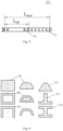
- Figure 9 shows preferred cross-sectional views of the preferred embodiments of the compensating element 50. From top to bottom and from left to right, these are a full or solid rectangle, a hollow rectangle or box profile, a U-shape, a full or solid circular layer, a hollow circular layer, a hollow circular layer open at the bottom, a full or solid trapezoidal shape, a T-shape or a double T-shape.
- the term circular layer is understood to mean a cross-sectional shape which, analogous to a spherical disk or spherical layer, represents a part of a circle which is cut out by two parallel straight lines. It is also possible to use an L-shape, a triangle, a solid or hollow semicircle or the like.
- the problems identified initially can be taken into account by a suitable choice of the cross-sectional shape of the compensating element 50. This is because different area moments of inertia offer a possibility to adjust the centricity.
- the compensating element 50 therefore preferably has a first axial area moment of inertia in cross-section and a second axial area moment of inertia that is greater than the first axial area moment of inertia.
- the at least one compensating element 50 is also arranged such that the second axial area moment of inertia acts perpendicular to the frame plane R.
- the axial area moment of inertia takes into account the cross-sectional dependency of the bending of the at least one compensating element 50 under load. The bending of the at least one compensating element 50 is smaller the larger the axial area moment of inertia.
- the at least one compensating element 50 in the present embodiment is preferably arranged on the first leg 20 in such a way that gravity causes the smaller bending.
- the larger axial area moment of inertia thus acts perpendicular to the frame plane R.
- a compensating element 50 that is rectangular in cross-section. In cross-section, this has a height h that is greater than its width b.
- this rectangular compensation element 50 is arranged on the first leg so that the height h is parallel to the x-axis and the width b is parallel to the z-axis, i.e. from the frame plane out, then the axial area moment of inertia of the compensating element 50 is calculated for a bending about an axis parallel to the x-axis, ie for a gravity-induced bending, as h ⁇ b 3 12 .
- the compensation element 50 is arranged on the first leg 20 such that the width b extends parallel to the x-axis and the height h parallel to the z-axis out of the frame plane, then the axial area moment of inertia in the case of a bending about an axis parallel to the x-axis, ie in the case of a gravity-induced bending, is calculated as b ⁇ h 3 12 .
- the compensating element 50 and its cross-sectional shape are used particularly effectively.
- the larger area moment of inertia acts in the frame plane R, namely when bending about an axis parallel to the z-axis.
- the selected effective length L eff of the compensation element 50 as well as the mounting position offer further adjustment options and are dependent on the weight forces and the respective lengths of the lever arms measured from the connection, ie top or middle, to the force application point, ie the drive end 22, 32.
- Figure 10 the additional use of slot nuts 56, which are used in particular for hollow and shell profiles. These prevent deformation as a result of excessive tightening or fastening torque when fastening the compensation element 50.
- T-nuts 56 can be used to vary the distance of the compensation element 50 from the frame plane R of the C-shaped tool holder 1.
- T-nuts 56 are used which have different extensions parallel to the z-axis, which increases the Steiner component (Steiner's theorem) and thus the area moment of inertia. This is explained below with reference to the Figures 10-12 clarified, whereby Figure 12 the cross-section of the first leg 20 with two laterally attached compensation elements 50.
- stiffening elements such as profiles, springs and dampers are installed symmetrically to the frame plane R in a C-shaped tool holder, whereby the operating force-induced bending of the tool holder is minimized.
- stiffening elements such as profiles, springs and dampers are installed symmetrically to the frame plane R in a C-shaped tool holder, whereby the operating force-induced bending of the tool holder is minimized.
- the example discussed in the introductory part is DE 10 2007 020 166 A1 referred to.
- I P,x,ges . represents the total area moment of inertia of the compensation element 50
- I P,x . is the area moment of inertia of the compensation element 50 related to or around the x-axis
- l P,z is the distance of the area center of gravity S F of the compensation element 50 from the reference axis
- ie the x-axis is the cross-sectional area of the compensation element 50.
- Figure 12 also the width bc of the first leg 20 as well as the cross-sectional area A C of the upper leg 20 and the bending moment M about the x-axis are shown.
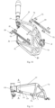
- Figure 13 shows the attachment of a compensation element 50 when using the upper fastening option 14 for the connection unit 3.
- the compensation element 50 was attached in particular along the connecting piece 40.
- the decisive factor for the alignment of the compensation element 50 is the bending moment, ie the effective force of gravity multiplied by the lever arm, i.e. the distance between the force application point and the connection unit 3.
- a first step A the C-shaped tool holder 1 is arranged so that the frame plane R is aligned perpendicular to gravity. Then, in step B, a first offset of the first leg 20 relative to the frame plane R is determined, and in step C, a second offset of the second leg 30 relative to the frame plane R is determined. Steps B and C can be carried out one after the other or simultaneously, with the order of steps B and C being arbitrary.
- step D at least one compensation element 50 is attached to one or more of the first leg 20, the second leg 30 or the connecting piece 40. This minimizes an offset difference ⁇ z_ between the working end 22 of the first leg 20 and the working end 32 of the second leg 30 (step E).
- step F an intersection point S of a first straight line G 1 , which corresponds to a direction of movement of the stamp in the direction of the working end 32 of the second leg 30, and a second straight line G 2 which runs from the working end 32 of the second leg 30 in the direction of the working end 22 of the first leg 20, is set by the at least one compensating element 50 to a working point.
Landscapes
- Engineering & Computer Science (AREA)
- Mechanical Engineering (AREA)
- Bending Of Plates, Rods, And Pipes (AREA)
- Manipulator (AREA)
- Mounting, Exchange, And Manufacturing Of Dies (AREA)
Claims (17)
- Porte-outil en forme de C (1) doté d'une structure de cadre (10) définissant un plan de cadre (R), comportant :a) une première branche (20) et une deuxième branche (30) disposée en face de la première branche (20), lesquelles présentent respectivement une extrémité de raccordement et une extrémité de travail (22, 32),b) une pièce de raccordement (40) par le biais de laquelle la première (20) et la deuxième branche (30) sont reliées entre elles à l'extrémité de raccordement respective, dans lequelc) l'extrémité de travail (22) de la première branche (20) est destinée à la fixation d'un poinçon (24) avec une unité d'entraînement associée, laquelle définit une direction de déplacement du poinçon (24) dans la direction de l'extrémité de travail (32) de la deuxième branche (30), et l'extrémité de travail (32) de la deuxième branche (30) est destinée à la fixation d'un dôme de matrice (34), dans lequeld) une différence de décalage (Δz) due à un décalage engendré par la force de gravité entre l'extrémité de travail (22) de la première (20) et l'extrémité de travail (32) de la deuxième branche (30) perpendiculairement au plan de cadre (R) peut être minimisée par au moins un élément de compensation (50) disposé sur l'un ou plusieurs des éléments suivants : la première branche (20), la deuxième branche (30) ou la pièce de raccordement (40),
caractérisé en ce quee) un point d'intersection (S) entre une première droite (G1) correspondant à la direction de déplacement du poinçon (24) dans la direction de l'extrémité de travail (32) de la deuxième branche (30) et une deuxième droite (G2) s'étendant à partir de l'extrémité de travail de la deuxième branche (30) dans la direction de l'extrémité de travail de la première branche (20), peut être réglé sur un point de travail par l'au moins un élément de compensation (50). - Porte-outil en forme de C (1) selon la revendication 1, dans lequel, dans la section transversale, l'au moins un élément de compensation (50) présente un premier moment d'inertie de surface axial et un deuxième moment d'inertie de surface axial, lequel est supérieur au premier moment d'inertie de surface axial, et l'au moins un élément de compensation (50) est disposé de telle façon que le deuxième moment d'inertie de surface axial agit perpendiculairement au plan de cadre (R).
- Porte-outil en forme de C (1) selon l'une des revendications précédentes, dans lequel l'élément de compensation (50) présente une forme de profilé présentant l'une des formes suivantes dans la section transversale : rectangulaire, semi-circulaire, en couche de cercle, triangulaire, en forme de T, en forme de double T, en forme de L, en forme de U, trapézoïdale ou une combinaison de celles-ci.
- Porte-outil en forme de C (1) selon l'une des revendications précédentes, dans lequel l'au moins un élément de compensation (50) présente au moins deux points de fixation, de préférence au moins quatre, six, huit ou dix points de fixation et de façon particulièrement préférée une multitude de points de fixation.
- Porte-outil en forme de C (1) selon l'une des revendications précédentes, dans lequel l'élément de compensation (50) présente la forme d'un profilé creux ou d'un profilé en coque et deux coulisseaux (56) sont en outre prévus entre l'élément de compensation (50) et la première branche (20), la deuxième branche (30) ou la pièce de raccordement (40).
- Porte-outil en forme de C (1) selon l'une des revendications précédentes, dans lequel l'élément de compensation (50) est disposé de façon amovible sur l'une respective parmi les branches (20, 30) et la pièce de raccordement (40), de préférence à l'aide de vis, de tiges (54), d'agrafes ou de pinces.
- Porte-outil en forme de C (1) selon l'une des revendications précédentes, lequel présente deux éléments de compensation (50).
- Porte-outil en forme de C (1) selon l'une des revendications précédentes, lequel présente une structure de cadre du genre treillis (10).
- Porte-outil en forme de C (1) selon l'une des revendications précédentes, lequel présente un poinçon (24) avec une unité d'entraînement associée à l'extrémité de travail (22) de la première branche (20) et un dôme de matrice (30) à l'extrémité de travail (32) de la deuxième branche (30).
- Appareil de pose doté d'un porte-outil en forme de C (1) selon l'une des revendications précédentes, dans lequel un poinçon (24) avec une unité d'entraînement associée est fixé à l'extrémité de travail (22) de la première branche (20) et un dôme de matrice (34) est fixé à l'extrémité de travail (32) de la deuxième branche (30).
- Appareil de pose selon la revendication 10, dans lequel l'appareil de pose est fixé à un robot à plusieurs axes par le biais du porte-outil en forme de C (1).
- Procédé de réglage d'une différence de décalage (Δz) entre une première (20) et une deuxième branche (30) d'un porte-outil en forme de C (1) selon l'une des revendications 1 à 9, comportant les étapes suivantes :a. disposition (A) du porte-outil en forme de C (1) de telle façon qu'un plan de cadre (R) est orienté perpendiculairement à la force de gravité, ensuiteb. détermination (B) d'un premier décalage de la première branche (20) par rapport au plan de cadre (R) etc. détermination (C) d'un deuxième décalage de la deuxième branche (30) par rapport au plan de cadre (R), puisd. fixation (D) d'au moins un élément de compensation (50) sur l'une ou plusieurs parmi la première branche (20), la deuxième branche (30) ou la pièce de raccordement (40), ete. minimisation (E) d'une différence de décalage (Δz) entre l'extrémité de travail (22) de la première branche (20) et l'extrémité de travail (32) de la deuxième branche (30).
- Procédé selon la revendication 12, comprenant l'étape supplémentaire suivante :
f. réglage (F) d'un point d'intersection (S) entre une première droite (G1) correspondant à la direction de déplacement du poinçon (24) dans la direction de l'extrémité de travail (32) de la deuxième branche (30) et une deuxième droite (G2) s'étendant à partir de l'extrémité de travail (32) de la deuxième branche (30) dans la direction de l'extrémité de travail (22) de la première branche (20), sur un point de travail par l'au moins un élément de compensation (50). - Procédé selon l'une des revendications 12 ou 13, dans lequel, dans la section transversale, l'au moins un élément de compensation (50) présente un premier moment d'inertie de surface axial et un deuxième moment d'inertie de surface axial, lequel est supérieur au premier moment d'inertie de surface axial, et l'étape de fixation (D) est effectuée de telle façon que l'élément de compensation (50) est disposé de manière à ce que le deuxième moment d'inertie de surface axial agisse perpendiculairement au plan de cadre (R).
- Procédé selon l'une des revendications 12 à 14, dans lequel l'au moins un élément de compensation (50) est fixé à la première branche (20), la deuxième branche (30) ou la pièce de raccordement (40) par le biais d'au moins deux points de fixation.
- Procédé selon l'une des revendications 12 à 15, dans lequel l'au moins un élément de compensation (50) est disposé de façon amovible sur la première branche (20), la deuxième branche (30) ou la pièce de raccordement (40), de préférence à l'aide de vis, de tiges (54), d'agrafes ou de pinces.
- Procédé selon l'une des revendications 12 à 16, dans lequel l'au moins un élément de compensation (50) présente la forme d'un profilé creux ou d'un profilé en coque et au moins deux coulisseaux (56) sont en outre prévus entre l'élément de compensation (50) et la première branche (20), la deuxième branche (30) ou la pièce de raccordement (40).
Priority Applications (3)
| Application Number | Priority Date | Filing Date | Title |
|---|---|---|---|
| EP22181365.2A EP4299207B1 (fr) | 2022-06-27 | 2022-06-27 | Porte-outil en forme de c, appareil de pose doté du porte-outil en forme de c et procédé de réglage d'une différence de décalage du porte-outil en forme de c |
| US18/214,314 US20230415222A1 (en) | 2022-06-27 | 2023-06-26 | C-shaped tool holder, setting device with the c-shaped tool holder and method for setting an offset difference of the c-shaped tool holder |
| CN202310768722.0A CN117299940A (zh) | 2022-06-27 | 2023-06-27 | C形刀架、具有c形刀架的设置装置和设置c形刀架偏移差的方法 |
Applications Claiming Priority (1)
| Application Number | Priority Date | Filing Date | Title |
|---|---|---|---|
| EP22181365.2A EP4299207B1 (fr) | 2022-06-27 | 2022-06-27 | Porte-outil en forme de c, appareil de pose doté du porte-outil en forme de c et procédé de réglage d'une différence de décalage du porte-outil en forme de c |
Publications (2)
| Publication Number | Publication Date |
|---|---|
| EP4299207A1 EP4299207A1 (fr) | 2024-01-03 |
| EP4299207B1 true EP4299207B1 (fr) | 2025-03-05 |
Family
ID=82321412
Family Applications (1)
| Application Number | Title | Priority Date | Filing Date |
|---|---|---|---|
| EP22181365.2A Active EP4299207B1 (fr) | 2022-06-27 | 2022-06-27 | Porte-outil en forme de c, appareil de pose doté du porte-outil en forme de c et procédé de réglage d'une différence de décalage du porte-outil en forme de c |
Country Status (3)
| Country | Link |
|---|---|
| US (1) | US20230415222A1 (fr) |
| EP (1) | EP4299207B1 (fr) |
| CN (1) | CN117299940A (fr) |
Family Cites Families (15)
| Publication number | Priority date | Publication date | Assignee | Title |
|---|---|---|---|---|
| US2296051A (en) * | 1940-06-19 | 1942-09-15 | Hydraulic Dev Corp Inc | Balancing column for horn presses |
| GB1181941A (en) * | 1968-02-08 | 1970-02-18 | Norton Tool Company Ltd | Presses |
| SE364469B (fr) * | 1973-01-19 | 1974-02-25 | Carbox Ab | |
| SU631361A1 (ru) * | 1977-03-28 | 1978-11-05 | Челябинский Политехнический Институт Имени Ленинского Комсомола | Предварительно напр женна собразна станина пресса |
| DE3809327A1 (de) * | 1988-03-19 | 1989-10-05 | Peddinghaus Carl Ullrich Dr | Stanze mit einem in der seitenansicht liegend u-foermigen maschinengestell |
| US5060362A (en) * | 1990-07-10 | 1991-10-29 | Gemcor Engineering Corp. | Slug riveting method and apparatus with C-frame deflection compensation |
| GB9602223D0 (en) * | 1996-02-03 | 1996-04-03 | Ariel Ind Plc | A flexure-free applicator |
| SE512242C2 (sv) * | 1998-06-18 | 2000-02-14 | Flexprop Production Ab | Verktygshållare |
| DE29818082U1 (de) * | 1998-10-09 | 1998-12-24 | Böllhoff GmbH, 33649 Bielefeld | Aufhängung für ein handgeführtes Montagewerkzeug |
| DE102005043211A1 (de) * | 2005-09-09 | 2007-03-15 | Newfrey Llc, Newark | Fügevorrichtung zum umformtechnischen Fügen |
| DE102007020166A1 (de) | 2007-04-26 | 2008-10-30 | Robert Bosch Gmbh | Werkzeughalter mit mechanischen Wirkmitteln |
| KR101392965B1 (ko) * | 2012-08-23 | 2014-05-08 | 충북대학교 산학협력단 | 셀프 피어싱 리벳 장치 및 그의 엔빌유닛 |
| US8935949B2 (en) * | 2012-10-09 | 2015-01-20 | The Boeing Company | C frame structure configured to provide deflection compensation and associated method |
| DE102014109144B4 (de) * | 2014-06-30 | 2021-12-30 | Modus One Gmbh | Verbesserte C-Gestell-Presse |
| DE102019122982A1 (de) * | 2019-08-27 | 2021-03-04 | Profil Verbindungstechnik Gmbh & Co. Kg | Werkzeughalter |
-
2022
- 2022-06-27 EP EP22181365.2A patent/EP4299207B1/fr active Active
-
2023
- 2023-06-26 US US18/214,314 patent/US20230415222A1/en active Pending
- 2023-06-27 CN CN202310768722.0A patent/CN117299940A/zh active Pending
Also Published As
| Publication number | Publication date |
|---|---|
| CN117299940A (zh) | 2023-12-29 |
| EP4299207A1 (fr) | 2024-01-03 |
| US20230415222A1 (en) | 2023-12-28 |
Similar Documents
| Publication | Publication Date | Title |
|---|---|---|
| DE3788773T2 (de) | Vorrichtung zur Feinverstellung und Vorrichtung zum Steuern dieser Verstellungen. | |
| EP2616197B1 (fr) | Dispositif et procédé pour fabriquer des profilés creux au moins partiellement fermés au moyen de demi-matrices rotatives avec un temps de cycle réduit | |
| DE3841416A1 (de) | Vorrichtung zur vergroesserung sehr kleiner verschiebungen und druckkopf unter verwendung dieser vorrichtung | |
| DE102022101667B4 (de) | Positioniervorrichtung zum positionieren eines von einer federwickelmaschine zugeführten federprodukts | |
| EP1425513A1 (fr) | Dispositif de detection et procede pour placer un dispositif de detection sur une plaque de montage | |
| EP2350479B1 (fr) | Structure de fixation et procédé de fixation d'un rail de guidage d'un système de guidage linéaire | |
| EP4299207B1 (fr) | Porte-outil en forme de c, appareil de pose doté du porte-outil en forme de c et procédé de réglage d'une différence de décalage du porte-outil en forme de c | |
| DE4310773C2 (de) | Vorrichtung zum freien plastischen Biegen eines Werkstücks | |
| EP3892907A1 (fr) | Bâti de machine pour une machine-outil et machine-outil | |
| AT518538B1 (de) | Bearbeitungsmaschine zum Bearbeiten von Werkstücken | |
| EP3401036B1 (fr) | Ensemble d'outils à composants d'outil permettant de configurer des outils de cintrage | |
| EP2616198B1 (fr) | Dispositif et procédé pour fabriquer des profilés creux au moins partiellement fermés avec un temps de cycle réduit | |
| DE60302312T2 (de) | Abkantpresse mit einem im Wesentlichen formstabilen Werkzeughaltebalken | |
| DE102009026297A1 (de) | Cockpitquerträger mit variablem Lenksäulenneigungswinkel | |
| EP4103329B1 (fr) | Bielle de réaction destinée à intercepter un couple d'entraînement et ensemble rouleaux muni d'une bielle de réaction | |
| DE69826958T2 (de) | Brammenkalibrierpresse | |
| EP3061538B1 (fr) | Presse plieuse | |
| DE4410248C1 (de) | Piezoelektrische Antriebsvorrichtung | |
| DE102005001845A1 (de) | Stabilisator für eine Portalwerkzeugmaschine und Portalwerkzeugmaschine | |
| DE4402061C1 (de) | Feststehendes Portal für Präzisions-Koordinatenmeßgeräte | |
| AT526736B1 (de) | Optimierter Tisch für Biegemaschine | |
| EP4151790B1 (fr) | Entraînement de barre à passettes d'un métier à tricoter en chaîne | |
| DE19618167C2 (de) | Ablagestation für Blechteile zwischen zwei benachbarten Werkzeugstufen einer Transferpressenlinie | |
| EP4178738B1 (fr) | Dispositif de cintrage avec compensation de flexion | |
| DE60125864T2 (de) | Tragevorrichtung und Schwingungserzeuger |
Legal Events
| Date | Code | Title | Description |
|---|---|---|---|
| PUAI | Public reference made under article 153(3) epc to a published international application that has entered the european phase |
Free format text: ORIGINAL CODE: 0009012 |
|
| STAA | Information on the status of an ep patent application or granted ep patent |
Free format text: STATUS: REQUEST FOR EXAMINATION WAS MADE |
|
| 17P | Request for examination filed |
Effective date: 20230718 |
|
| AK | Designated contracting states |
Kind code of ref document: A1 Designated state(s): AL AT BE BG CH CY CZ DE DK EE ES FI FR GB GR HR HU IE IS IT LI LT LU LV MC MK MT NL NO PL PT RO RS SE SI SK SM TR |
|
| GRAP | Despatch of communication of intention to grant a patent |
Free format text: ORIGINAL CODE: EPIDOSNIGR1 |
|
| STAA | Information on the status of an ep patent application or granted ep patent |
Free format text: STATUS: GRANT OF PATENT IS INTENDED |
|
| RIC1 | Information provided on ipc code assigned before grant |
Ipc: B21D 39/03 20060101ALI20240909BHEP Ipc: B30B 15/04 20060101ALI20240909BHEP Ipc: B21J 15/10 20060101ALI20240909BHEP Ipc: B21J 15/02 20060101AFI20240909BHEP |
|
| INTG | Intention to grant announced |
Effective date: 20241002 |
|
| GRAS | Grant fee paid |
Free format text: ORIGINAL CODE: EPIDOSNIGR3 |
|
| GRAA | (expected) grant |
Free format text: ORIGINAL CODE: 0009210 |
|
| STAA | Information on the status of an ep patent application or granted ep patent |
Free format text: STATUS: THE PATENT HAS BEEN GRANTED |
|
| AK | Designated contracting states |
Kind code of ref document: B1 Designated state(s): AL AT BE BG CH CY CZ DE DK EE ES FI FR GB GR HR HU IE IS IT LI LT LU LV MC MK MT NL NO PL PT RO RS SE SI SK SM TR |
|
| REG | Reference to a national code |
Ref country code: GB Ref legal event code: FG4D Free format text: NOT ENGLISH |
|
| REG | Reference to a national code |
Ref country code: CH Ref legal event code: EP |
|
| REG | Reference to a national code |
Ref country code: IE Ref legal event code: FG4D Free format text: LANGUAGE OF EP DOCUMENT: GERMAN |
|
| REG | Reference to a national code |
Ref country code: DE Ref legal event code: R096 Ref document number: 502022003076 Country of ref document: DE |
|
| PG25 | Lapsed in a contracting state [announced via postgrant information from national office to epo] |
Ref country code: RS Free format text: LAPSE BECAUSE OF FAILURE TO SUBMIT A TRANSLATION OF THE DESCRIPTION OR TO PAY THE FEE WITHIN THE PRESCRIBED TIME-LIMIT Effective date: 20250605 |
|
| PG25 | Lapsed in a contracting state [announced via postgrant information from national office to epo] |
Ref country code: FI Free format text: LAPSE BECAUSE OF FAILURE TO SUBMIT A TRANSLATION OF THE DESCRIPTION OR TO PAY THE FEE WITHIN THE PRESCRIBED TIME-LIMIT Effective date: 20250305 |
|
| REG | Reference to a national code |
Ref country code: NL Ref legal event code: MP Effective date: 20250305 |
|
| PG25 | Lapsed in a contracting state [announced via postgrant information from national office to epo] |
Ref country code: ES Free format text: LAPSE BECAUSE OF FAILURE TO SUBMIT A TRANSLATION OF THE DESCRIPTION OR TO PAY THE FEE WITHIN THE PRESCRIBED TIME-LIMIT Effective date: 20250305 |
|
| REG | Reference to a national code |
Ref country code: LT Ref legal event code: MG9D |
|
| PG25 | Lapsed in a contracting state [announced via postgrant information from national office to epo] |
Ref country code: NO Free format text: LAPSE BECAUSE OF FAILURE TO SUBMIT A TRANSLATION OF THE DESCRIPTION OR TO PAY THE FEE WITHIN THE PRESCRIBED TIME-LIMIT Effective date: 20250605 |
|
| PG25 | Lapsed in a contracting state [announced via postgrant information from national office to epo] |
Ref country code: HR Free format text: LAPSE BECAUSE OF FAILURE TO SUBMIT A TRANSLATION OF THE DESCRIPTION OR TO PAY THE FEE WITHIN THE PRESCRIBED TIME-LIMIT Effective date: 20250305 |
|
| PG25 | Lapsed in a contracting state [announced via postgrant information from national office to epo] |
Ref country code: LV Free format text: LAPSE BECAUSE OF FAILURE TO SUBMIT A TRANSLATION OF THE DESCRIPTION OR TO PAY THE FEE WITHIN THE PRESCRIBED TIME-LIMIT Effective date: 20250305 |
|
| PGFP | Annual fee paid to national office [announced via postgrant information from national office to epo] |
Ref country code: FR Payment date: 20250618 Year of fee payment: 4 |
|
| PG25 | Lapsed in a contracting state [announced via postgrant information from national office to epo] |
Ref country code: GR Free format text: LAPSE BECAUSE OF FAILURE TO SUBMIT A TRANSLATION OF THE DESCRIPTION OR TO PAY THE FEE WITHIN THE PRESCRIBED TIME-LIMIT Effective date: 20250606 Ref country code: BG Free format text: LAPSE BECAUSE OF FAILURE TO SUBMIT A TRANSLATION OF THE DESCRIPTION OR TO PAY THE FEE WITHIN THE PRESCRIBED TIME-LIMIT Effective date: 20250305 |
|
| PGFP | Annual fee paid to national office [announced via postgrant information from national office to epo] |
Ref country code: AT Payment date: 20250721 Year of fee payment: 4 |
|
| PG25 | Lapsed in a contracting state [announced via postgrant information from national office to epo] |
Ref country code: NL Free format text: LAPSE BECAUSE OF FAILURE TO SUBMIT A TRANSLATION OF THE DESCRIPTION OR TO PAY THE FEE WITHIN THE PRESCRIBED TIME-LIMIT Effective date: 20250305 |
|
| PG25 | Lapsed in a contracting state [announced via postgrant information from national office to epo] |
Ref country code: SE Free format text: LAPSE BECAUSE OF FAILURE TO SUBMIT A TRANSLATION OF THE DESCRIPTION OR TO PAY THE FEE WITHIN THE PRESCRIBED TIME-LIMIT Effective date: 20250305 |
|
| PG25 | Lapsed in a contracting state [announced via postgrant information from national office to epo] |
Ref country code: SM Free format text: LAPSE BECAUSE OF FAILURE TO SUBMIT A TRANSLATION OF THE DESCRIPTION OR TO PAY THE FEE WITHIN THE PRESCRIBED TIME-LIMIT Effective date: 20250305 |
|
| PG25 | Lapsed in a contracting state [announced via postgrant information from national office to epo] |
Ref country code: PT Free format text: LAPSE BECAUSE OF FAILURE TO SUBMIT A TRANSLATION OF THE DESCRIPTION OR TO PAY THE FEE WITHIN THE PRESCRIBED TIME-LIMIT Effective date: 20250707 |
|
| PGFP | Annual fee paid to national office [announced via postgrant information from national office to epo] |
Ref country code: DE Payment date: 20250827 Year of fee payment: 4 |
|
| PG25 | Lapsed in a contracting state [announced via postgrant information from national office to epo] |
Ref country code: IT Free format text: LAPSE BECAUSE OF FAILURE TO SUBMIT A TRANSLATION OF THE DESCRIPTION OR TO PAY THE FEE WITHIN THE PRESCRIBED TIME-LIMIT Effective date: 20250305 Ref country code: PL Free format text: LAPSE BECAUSE OF FAILURE TO SUBMIT A TRANSLATION OF THE DESCRIPTION OR TO PAY THE FEE WITHIN THE PRESCRIBED TIME-LIMIT Effective date: 20250305 |
|
| PG25 | Lapsed in a contracting state [announced via postgrant information from national office to epo] |
Ref country code: EE Free format text: LAPSE BECAUSE OF FAILURE TO SUBMIT A TRANSLATION OF THE DESCRIPTION OR TO PAY THE FEE WITHIN THE PRESCRIBED TIME-LIMIT Effective date: 20250305 Ref country code: CZ Free format text: LAPSE BECAUSE OF FAILURE TO SUBMIT A TRANSLATION OF THE DESCRIPTION OR TO PAY THE FEE WITHIN THE PRESCRIBED TIME-LIMIT Effective date: 20250305 |
|
| PG25 | Lapsed in a contracting state [announced via postgrant information from national office to epo] |
Ref country code: RO Free format text: LAPSE BECAUSE OF FAILURE TO SUBMIT A TRANSLATION OF THE DESCRIPTION OR TO PAY THE FEE WITHIN THE PRESCRIBED TIME-LIMIT Effective date: 20250305 |
|
| PG25 | Lapsed in a contracting state [announced via postgrant information from national office to epo] |
Ref country code: SK Free format text: LAPSE BECAUSE OF FAILURE TO SUBMIT A TRANSLATION OF THE DESCRIPTION OR TO PAY THE FEE WITHIN THE PRESCRIBED TIME-LIMIT Effective date: 20250305 |
|
| PG25 | Lapsed in a contracting state [announced via postgrant information from national office to epo] |
Ref country code: IS Free format text: LAPSE BECAUSE OF FAILURE TO SUBMIT A TRANSLATION OF THE DESCRIPTION OR TO PAY THE FEE WITHIN THE PRESCRIBED TIME-LIMIT Effective date: 20250705 |
|
| REG | Reference to a national code |
Ref country code: DE Ref legal event code: R097 Ref document number: 502022003076 Country of ref document: DE |
|
| PLBE | No opposition filed within time limit |
Free format text: ORIGINAL CODE: 0009261 |
|
| STAA | Information on the status of an ep patent application or granted ep patent |
Free format text: STATUS: NO OPPOSITION FILED WITHIN TIME LIMIT |
|
| PG25 | Lapsed in a contracting state [announced via postgrant information from national office to epo] |
Ref country code: DK Free format text: LAPSE BECAUSE OF FAILURE TO SUBMIT A TRANSLATION OF THE DESCRIPTION OR TO PAY THE FEE WITHIN THE PRESCRIBED TIME-LIMIT Effective date: 20250305 |
|
| REG | Reference to a national code |
Ref country code: CH Ref legal event code: L10 Free format text: ST27 STATUS EVENT CODE: U-0-0-L10-L00 (AS PROVIDED BY THE NATIONAL OFFICE) Effective date: 20260114 |
|
| REG | Reference to a national code |
Ref country code: CH Ref legal event code: H13 Free format text: ST27 STATUS EVENT CODE: U-0-0-H10-H13 (AS PROVIDED BY THE NATIONAL OFFICE) Effective date: 20260127 |
|
| PG25 | Lapsed in a contracting state [announced via postgrant information from national office to epo] |
Ref country code: MC Free format text: LAPSE BECAUSE OF FAILURE TO SUBMIT A TRANSLATION OF THE DESCRIPTION OR TO PAY THE FEE WITHIN THE PRESCRIBED TIME-LIMIT Effective date: 20250305 |
|
| 26N | No opposition filed |
Effective date: 20251208 |
|
| PG25 | Lapsed in a contracting state [announced via postgrant information from national office to epo] |
Ref country code: LU Free format text: LAPSE BECAUSE OF NON-PAYMENT OF DUE FEES Effective date: 20250627 |
|
| REG | Reference to a national code |
Ref country code: BE Ref legal event code: MM Effective date: 20250630 |
|
| PG25 | Lapsed in a contracting state [announced via postgrant information from national office to epo] |
Ref country code: IE Free format text: LAPSE BECAUSE OF NON-PAYMENT OF DUE FEES Effective date: 20250627 |
|
| PG25 | Lapsed in a contracting state [announced via postgrant information from national office to epo] |
Ref country code: BE Free format text: LAPSE BECAUSE OF NON-PAYMENT OF DUE FEES Effective date: 20250630 |