EP4299251B1 - Outil électrique - Google Patents
Outil électrique Download PDFInfo
- Publication number
- EP4299251B1 EP4299251B1 EP21928134.2A EP21928134A EP4299251B1 EP 4299251 B1 EP4299251 B1 EP 4299251B1 EP 21928134 A EP21928134 A EP 21928134A EP 4299251 B1 EP4299251 B1 EP 4299251B1
- Authority
- EP
- European Patent Office
- Prior art keywords
- rotating part
- motor
- torque
- clutch mechanism
- state
- Prior art date
- Legal status (The legal status is an assumption and is not a legal conclusion. Google has not performed a legal analysis and makes no representation as to the accuracy of the status listed.)
- Active
Links
Images

Classifications
-
- B—PERFORMING OPERATIONS; TRANSPORTING
- B25—HAND TOOLS; PORTABLE POWER-DRIVEN TOOLS; MANIPULATORS
- B25B—TOOLS OR BENCH DEVICES NOT OTHERWISE PROVIDED FOR, FOR FASTENING, CONNECTING, DISENGAGING, OR HOLDING
- B25B21/00—Portable power-driven screw or nut setting or loosening tools; Attachments for drilling apparatus serving the same purpose
-
- B—PERFORMING OPERATIONS; TRANSPORTING
- B25—HAND TOOLS; PORTABLE POWER-DRIVEN TOOLS; MANIPULATORS
- B25B—TOOLS OR BENCH DEVICES NOT OTHERWISE PROVIDED FOR, FOR FASTENING, CONNECTING, DISENGAGING, OR HOLDING
- B25B23/00—Details of, or accessories for, spanners, wrenches, screwdrivers
- B25B23/14—Arrangement of torque limiters or torque indicators in wrenches or screwdrivers
- B25B23/147—Arrangement of torque limiters or torque indicators in wrenches or screwdrivers specially adapted for electrically operated wrenches or screwdrivers
-
- B—PERFORMING OPERATIONS; TRANSPORTING
- B25—HAND TOOLS; PORTABLE POWER-DRIVEN TOOLS; MANIPULATORS
- B25F—COMBINATION OR MULTI-PURPOSE TOOLS NOT OTHERWISE PROVIDED FOR; DETAILS OR COMPONENTS OF PORTABLE POWER-DRIVEN TOOLS NOT PARTICULARLY RELATED TO THE OPERATIONS PERFORMED AND NOT OTHERWISE PROVIDED FOR
- B25F5/00—Details or components of portable power-driven tools not particularly related to the operations performed and not otherwise provided for
-
- B—PERFORMING OPERATIONS; TRANSPORTING
- B25—HAND TOOLS; PORTABLE POWER-DRIVEN TOOLS; MANIPULATORS
- B25F—COMBINATION OR MULTI-PURPOSE TOOLS NOT OTHERWISE PROVIDED FOR; DETAILS OR COMPONENTS OF PORTABLE POWER-DRIVEN TOOLS NOT PARTICULARLY RELATED TO THE OPERATIONS PERFORMED AND NOT OTHERWISE PROVIDED FOR
- B25F5/00—Details or components of portable power-driven tools not particularly related to the operations performed and not otherwise provided for
- B25F5/001—Gearings, speed selectors, clutches or the like specially adapted for rotary tools
-
- F—MECHANICAL ENGINEERING; LIGHTING; HEATING; WEAPONS; BLASTING
- F16—ENGINEERING ELEMENTS AND UNITS; GENERAL MEASURES FOR PRODUCING AND MAINTAINING EFFECTIVE FUNCTIONING OF MACHINES OR INSTALLATIONS; THERMAL INSULATION IN GENERAL
- F16D—COUPLINGS FOR TRANSMITTING ROTATION; CLUTCHES; BRAKES
- F16D27/00—Magnetically- or electrically- actuated clutches; Control or electric circuits therefor
- F16D27/01—Magnetically- or electrically- actuated clutches; Control or electric circuits therefor with permanent magnets
-
- F—MECHANICAL ENGINEERING; LIGHTING; HEATING; WEAPONS; BLASTING
- F16—ENGINEERING ELEMENTS AND UNITS; GENERAL MEASURES FOR PRODUCING AND MAINTAINING EFFECTIVE FUNCTIONING OF MACHINES OR INSTALLATIONS; THERMAL INSULATION IN GENERAL
- F16D—COUPLINGS FOR TRANSMITTING ROTATION; CLUTCHES; BRAKES
- F16D27/00—Magnetically- or electrically- actuated clutches; Control or electric circuits therefor
- F16D27/02—Magnetically- or electrically- actuated clutches; Control or electric circuits therefor with electromagnets incorporated in the clutch, i.e. with collecting rings
-
- F—MECHANICAL ENGINEERING; LIGHTING; HEATING; WEAPONS; BLASTING
- F16—ENGINEERING ELEMENTS AND UNITS; GENERAL MEASURES FOR PRODUCING AND MAINTAINING EFFECTIVE FUNCTIONING OF MACHINES OR INSTALLATIONS; THERMAL INSULATION IN GENERAL
- F16D—COUPLINGS FOR TRANSMITTING ROTATION; CLUTCHES; BRAKES
- F16D27/00—Magnetically- or electrically- actuated clutches; Control or electric circuits therefor
- F16D27/10—Magnetically- or electrically- actuated clutches; Control or electric circuits therefor with an electromagnet not rotating with a clutching member, i.e. without collecting rings
- F16D27/108—Magnetically- or electrically- actuated clutches; Control or electric circuits therefor with an electromagnet not rotating with a clutching member, i.e. without collecting rings with axially movable clutching members
-
- F—MECHANICAL ENGINEERING; LIGHTING; HEATING; WEAPONS; BLASTING
- F16—ENGINEERING ELEMENTS AND UNITS; GENERAL MEASURES FOR PRODUCING AND MAINTAINING EFFECTIVE FUNCTIONING OF MACHINES OR INSTALLATIONS; THERMAL INSULATION IN GENERAL
- F16D—COUPLINGS FOR TRANSMITTING ROTATION; CLUTCHES; BRAKES
- F16D27/00—Magnetically- or electrically- actuated clutches; Control or electric circuits therefor
- F16D27/10—Magnetically- or electrically- actuated clutches; Control or electric circuits therefor with an electromagnet not rotating with a clutching member, i.e. without collecting rings
- F16D27/118—Magnetically- or electrically- actuated clutches; Control or electric circuits therefor with an electromagnet not rotating with a clutching member, i.e. without collecting rings with interengaging jaws or gear teeth
-
- F—MECHANICAL ENGINEERING; LIGHTING; HEATING; WEAPONS; BLASTING
- F16—ENGINEERING ELEMENTS AND UNITS; GENERAL MEASURES FOR PRODUCING AND MAINTAINING EFFECTIVE FUNCTIONING OF MACHINES OR INSTALLATIONS; THERMAL INSULATION IN GENERAL
- F16D—COUPLINGS FOR TRANSMITTING ROTATION; CLUTCHES; BRAKES
- F16D27/00—Magnetically- or electrically- actuated clutches; Control or electric circuits therefor
- F16D27/14—Details
-
- F—MECHANICAL ENGINEERING; LIGHTING; HEATING; WEAPONS; BLASTING
- F16—ENGINEERING ELEMENTS AND UNITS; GENERAL MEASURES FOR PRODUCING AND MAINTAINING EFFECTIVE FUNCTIONING OF MACHINES OR INSTALLATIONS; THERMAL INSULATION IN GENERAL
- F16D—COUPLINGS FOR TRANSMITTING ROTATION; CLUTCHES; BRAKES
- F16D43/00—Automatic clutches
Definitions
- the present disclosure generally relates to an electric tool, and more particularly relates to an electric tool including a clutch mechanism.
- Patent Literature 1 discloses an electric rotary tool (electric tool).
- the electric tool includes a motor unit (motor) and a control circuit section for controlling the motor unit.
- the control circuit section calculates fastening torque based on either a drive current for the motor unit as detected by a current detection means or the number of revolutions of the motor unit as detected by a number of revolutions detection means. When the fastening torque thus calculated becomes equal to or greater than preset fastening torque, the control circuit section stops running the motor unit.
- Patent Literature 1 JP 2009-202317 A Document US 2013/192860 A1 describes a mode change mechanism for a power tool including an actuator with a permanent magnet.
- the actuator is moveable between a first position for a first mode of operation, and a second position for a second mode of operation.
- a first positioning member is adjacent the first position composed of a ferromagnetic material to attract the permanent magnet.
- a second positioning member is adjacent the second position and composed of a ferromagnetic material to attract the permanent magnet.
- An electromagnet may be energized to move the actuator between the first position and the second position. When the electromagnet is not energized, and the actuator is in the first position. the actuator is retained in the first position. When the electromagnet is not energized and the actuator is in the second position, the actuator is retained in the second position. When the electromagnet is energized, the actuator moves between the first and second positions.
- Document JP H11 77554 A describes a torque control system comprising an operation shaft for revolving a screw fixture combined with the output shaft at one end of an electromagnetic clutch mechanism, wherein the other end of the electromagnetic clutch mechanism is fixed inside a holding part casing through a supporting body extended coaxially with the mechanism.
- a strain gauge is attached to one side surface of the supporting body and the electromagnetic clutch mechanism is configured to be engaged/disengaged based on the output signal of the strain gauge.
- Document US 2019/283222 A1 describes a rotary power tool comprising a motor, an output shaft that receives torque from the motor, a clutch positioned between the motor and the output shaft for selectively engaging the output shaft to the motor, and a transducer for detecting an amount of torque transferred through the clutch to the output shaft.
- the clutch is capable of being actuated from a first mode in which the output shaft is engaged to the motor, to a second mode in which the output shaft is disengaged from the motor, in response to feedback from the transducer of the detected amount of torque transferred through the clutch.
- Document EP 2 412 484 A1 describes a hand-held power tool having a tool body, a motor housed in the tool body and a grip part designed to be held by a user and performs a predetermined operation on a workpiece by a tool bit rotationally driven by the motor.
- the power tool includes a clutch that transmits torque and interrupts torque transmission between the motor and the tool bit, a non-contact torque sensor that detects torque acting on the tool bit in non-contact with a rotation axis rotating together with the tool bit, and a clutch control system that controls coupling and decoupling of the clutch according to a torque value detected by the non-contact torque sensor.
- An object of the present disclosure is to control an electric tool more accurately according to torque (fastening torque).
- the controller 49 switches the clutch mechanism C1 from the transmitting state to the interrupted state according to the torque detected by the torque detection unit 6. That is to say, the clutch mechanism C1 is switched from the transmitting state to the interrupted state by an electronic control performed by the controller 49.
- a clutch mechanism for making a switch from the transmitting state to the interrupted state by mechanical action using torque, not by electronic control, is called a "mechanical clutch.”
- a switch is made from the transmitting state to the interrupted state if the torque is greater than a threshold value.
- the switch is made to the interrupted state with reliability if the torque is sufficiently greater than the threshold value, but the switch to the interrupted state may fail to be made the instant the torque reaches the threshold value.
- the clutch mechanism C1 includes an electromagnet 91 and switches between the transmitting state and the interrupted state by changing the energization state of the electromagnet 91. Nevertheless, not covered by the invention the clutch mechanism C1 does not have to have such a configuration including the electromagnet 91.
- the clutch mechanism C1 may also be a mechanical clutch for use with an actuator. In that case, the actuator may drive the mechanical clutch under the electronic control by the controller 49 to switch the mechanical clutch from the transmitting state to the interrupted state.
- the electric tool 1 may further include such an actuator.
- the actuator may include, for example, a cylinder which stretches and shrinks under the control of the controller 49.
- the tip tool 12 (also called a "bit”) may be a screwdriver bit or a drill bit, for example.
- One of various types of tip tools 12 is selected depending on the intended use and attached to the holder 11 for the intended use.
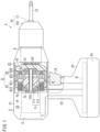
- the clutch mechanism C1 is interposed between the holder 11 and the motor 15. More specifically, the clutch mechanism C1 is interposed between the motor 15 and the transmission mechanism 3. While the clutch mechanism C1 is in the transmitting state, the clutch mechanism C1 transmits the torque of the motor 15 to the transmission mechanism 3. As a result, the torque of the motor 15 is transmitted to the holder 11 via the clutch mechanism C1 and the transmission mechanism 3. On the other hand, while the clutch mechanism C1 is in the interrupted state, the clutch mechanism C1 does not transmit the torque of the motor 15 to the transmission mechanism 3. As a result, the torque of the motor 15 is not transmitted to the holder 11.
- the transmitting state of the clutch mechanism C1 is a state where the first rotating part 71 and the second rotating part 81 are coupled to each other via the at least one coupling portion 9 so that the torque of the first rotating part 71 is transmitted to the second rotating part 81.
- the interrupted state of the clutch mechanism C1 is a state where the first rotating part 71 and the second rotating part 81 are decoupled from each other so that the torque of the first rotating part 71 is not transmitted to the second rotating part 81.
- the clutch mechanism C1 further includes a stator part 70, a first bearing 72, and a second bearing 82.
- the controller 49 while the controller 49 is performing control such that the magnitude of a current supplied to the coil 912 becomes equal to or greater than a predetermined magnitude, electromagnetic repulsive force is generated between the magnetic pole 911 and the permanent magnet 921, thus producing the interrupted state where the first rotating part 71 and the second rotating part 81 are decoupled from each other. That is to say, the controller 49 switches the clutch mechanism C1 from the transmitting state to the interrupted state by generating the electromagnetic repulsive force between the magnetic pole 911 and the permanent magnet 921.
- the clutch mechanism C1 turns into the interrupted state while the electromagnet 91 (coil 912) is energized with a current, of which the magnitude is equal to or greater than the predetermined magnitude.
- the clutch mechanism C1 turns into the transmitting state while the electromagnet 91 (coil 912) is not energized or if the electromagnet 91 (coil 912) is energized with a current, of which the magnitude is less than the predetermined magnitude.
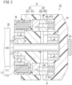
- the clutch mechanism C1 While the coil 912 is not energized or energized with a current, of which the magnitude is smaller than a predetermined magnitude, the clutch mechanism C1 maintains the transmitting state. While the clutch mechanism C1 is in the transmitting state, the permanent magnets 921 are inserted into the first recesses 713 of the first rotating part 71 as shown in FIG. 3 . At this time, each permanent magnet 921 is in contact with a corresponding one of the magnetic poles 911. More specifically, the permanent magnet 921 is sandwiched between the magnetic pole 911 and a corresponding one of the elastic members 922. The elastic energy applied by the elastic member 922 holds the permanent magnet 921 at the same position.
- the clutch mechanism C1 has a fitting structure, which is formed by the first recesses 713 and the permanent magnets 921. While the clutch mechanism C1 is in the transmitting state, the fitting structure couples the first rotating part 71 and the second rotating part 81 to each other by fitting.
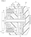
- the clutch mechanism C1 If the coils 912 are energized with a current, of which the magnitude is equal to or greater than a predetermined magnitude, while the clutch mechanism C1 is in the transmitting state, electromagnetic repulsive force is generated between the magnetic poles 911 and the permanent magnets 921, thus causing the permanent magnets 921 to move to the right. That is to say, the permanent magnets 921 come out of contact with the magnetic poles 911 while compressing the elastic members 922 to move out of the first recesses 713 of the first rotating part 71 as shown in FIG. 4 . More specifically, the permanent magnets 921 are retracted into the second recesses 813 of the second rotating part 81. Moving the permanent magnet 921 out of the first recess 713 in each of the coupling portions 9 decouples the first rotating part 71 and the second rotating part 81 from each other. That is to say, the clutch mechanism C1 turns into the interrupted state.
- While the clutch mechanism C1 is in the interrupted state, as the rotary shaft 132 of the motor 15 turns, only the first rotating part 71 rotates with the second rotating part 81 not rotating. In addition, the holder 11 and the tip tool 12 that are coupled to the second rotating part 81 via the transmission mechanism 3 do not rotate, either. More specifically, as the clutch mechanism C1 switches from the transmitting state to the interrupted state, the second rotating part 81, the plurality of gears of the transmission mechanism 3, the holder 11, and the tip tool 12 continue to rotate for a while due to the inertial energy but will soon stop rotating when the inertial energy is lost.
- each of the plurality of coupling portions 9 further includes the elastic member 922 that stores elastic energy while the electromagnet 91 is being energized. That is to say, letting the permanent magnet 921 compress the elastic member 922 causes the elastic member 922 to store elastic energy.
- the clutch mechanism C1 is caused to switch to either the transmitting state or the interrupted state by the elastic energy of the elastic member 922. In this embodiment, the clutch mechanism C1 is caused to switch from the interrupted state to the transmitting state by the elastic energy of the elastic member 922.
- the driver circuit section 5 is disposed adjacent to the motor 15.
- the driver circuit section 5 supplies power to the motor 15 under the control of the power control block 4.
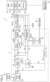
- the driver circuit section 5 includes an inverter circuit section 51 (refer to FIG. 2 ).
- the inverter circuit section 51 converts the power supplied from the power supply unit B1 into power with a desired voltage and supplies the power thus converted to the motor 15.
- the power control block 4 is used along with the inverter circuit section 51 and controls the operation of the motor 15 by feedback control.
- the power control block 4 includes a computer system including one or more processors and a memory. At least some of the functions of the power control block 4 are performed by making the processor(s) of the computer system execute a program stored in the memory of the computer system.
- the program may be stored in the memory.
- the program may also be downloaded via a telecommunications line such as the Internet or distributed after having been stored in a non-transitory storage medium such as a memory card.
- the power control block 4 includes a command value generator 41, a velocity controller 42, a current controller 43, a first coordinate transformer 44, a second coordinate transformer 45, a flux controller 46, an estimator 47, a controller 49, and a calculator 63. Note that these constituent elements of the power control block 4 just represent functions to be performed by the power control block 4 and do not always have a substantive configuration.
- the electric tool 1 further includes a plurality of (e.g., two in the example illustrated in FIG. 2 ) current sensors 61, 62.
- Each of the plurality of current sensors 61, 62 includes, for example, a hall element current sensor or a shunt resistor element.
- the plurality of current sensors 61, 62 measure an electric current supplied from the power supply unit B1 (refer to FIG. 1 ) to the motor 15 via the inverter circuit section 51.
- three-phase currents namely, a U-phase current, a V-phase current, and a W-phase current
- the plurality of current sensors 61, 62 measure currents in at least two phases. In FIG. 2 , the current sensor 61 measures the U-phase current to output a current measured value i u 1 and the current sensor 62 measures the V-phase current to output a current measured value i v 1.
- the estimator 47 obtains a time derivative of the rotational angle ⁇ 1, measured by the motor rotation measuring unit 27, of the motor 15 to calculate an angular velocity ⁇ 1 of the motor 15.
- the second coordinate transformer 45 performs, based on the rotational angle ⁇ 1, measured by the motor rotation measuring unit 27, of the motor 15, coordinate transformation on the current measured values i u 1, i v 1 measured by the plurality of current sensors 61, 62, thereby calculating current measured values id1, iq1. That is to say, the second coordinate transformer 45 transforms the current measured values i u 1, i v 1, corresponding to currents in two phases, into a current measured value id1 corresponding to a magnetic field component (d-axis current) and a current measured value iq1 corresponding to a torque component (q-axis current).
- the calculator 63 calculates, based on the torque current (current measured value iq1) measured by the current measuring unit 60, the torque to be transmitted from the motor 15 to the holder 11.
- the calculator 63 calculates the torque to be transmitted from the motor 15 to the holder 11 by, for example, multiplying the current measured value iq1 representing the torque current by a predetermined constant.
- the torque detection unit 6 may be a torque sensor.
- a torque sensor a resistive strain sensor or a magnetostrictive strain sensor may be used, for example.
- the controller (49) switches the clutch mechanism (C1) to the interrupted state according to the torque detected by the torque detection unit (6). This improves the accuracy of control according to the torque, compared to switching the clutch mechanism (C1) to the interrupted state by mechanical action according to the torque, not by electronic control by the controller (49).
- the torque detection unit (6) includes a current measuring unit (60) and a calculator (63).
- the current measuring unit (60) measures a torque current flowing through the motor (15).
- the calculator (63) calculates, based on the torque current measured by the current measuring unit (60), the torque transmitted from the motor (15) to the holder (11).
- This configuration allows the torque to be calculated based on the torque current.
- the transmission mechanism (3) reduces a rotational velocity of the motor (15).
- the clutch mechanism (C1) is interposed between the motor (15) and the transmission mechanism (3).
- the clutch mechanism (C1) includes a first rotating part (71), a second rotating part (81), and at least one coupling portion (9).
- the first rotating part (71) rotates as the motor (15) runs.
- the holder (11) is coupled either directly or indirectly to the second rotating part (81).
- the transmitting state is a state where the first rotating part (71) and the second rotating part (81) are coupled to each other via the at least one coupling portion (9) so that torque of the first rotating part (71) is transmitted to the second rotating part (81).
- the interrupted state is a state where the first rotating part (71) and the second rotating part (81) are decoupled from each other so that no torque of the first rotating part (71) is transmitted to the second rotating part (81).
- the at least one coupling portion (9) includes: an electromagnet (91) having a magnetic pole (911); and a permanent magnet (921) facing the magnetic pole (911).
- the magnetic pole (911) is held by the first rotating part (71).
- the permanent magnet (921) is held by the second rotating part (81).
- the controller (49) switches the clutch mechanism (C1) from the transmitting state to the interrupted state, or vice versa, by changing an energization state of the electromagnet (91).
- This configuration allows the clutch mechanism (C1) to be quickly switched from the transmitting state to the interrupted state.
- the clutch mechanism (C1) turns into the interrupted state when the electromagnet (91) is energized with a current, of which magnitude is equal to or greater than predetermined magnitude, and turns into the transmitting state when the electromagnet (91) is either not energized or energized with a current, of which magnitude is less than the predetermined magnitude.
- This configuration may cut down the power consumption in the transmitting state.
- the at least one coupling portion (9) further includes an elastic member (922).
- the elastic member (922) stores elastic energy while the electromagnet (91) is energized.
- the clutch mechanism (C1) is caused to switch from one state selected from the transmitting state and the interrupted state to the other state selected from the transmitting state and the interrupted state by the elastic energy of the elastic member (922).
- This configuration enables switching the clutch mechanism (C1) from the transmitting state to the interrupted state, or vice versa, using the elastic energy stored in the elastic member (922).
- the clutch mechanism (C1) further includes an input shaft (rotary shaft 132) and an output shaft (gear 83).
- the input shaft transmits the torque of the motor (15) to the first rotating part (71).
- the output shaft is arranged coaxially with the input shaft.
- the output shaft transmits rotational force of the second rotating part (81) to the holder (11).
- the input shaft and the output shaft are arranged coaxially with each other, thus reducing the axial runout of the input shaft and the output shaft.
- the clutch mechanism (C1) includes a plurality of the coupling portions (9).
- the plurality of the coupling portions (9) are arranged to surround at least one of the input shaft or the output shaft.
- the plurality of coupling portions (9) are arranged in a circle, thus reducing the bias of the force while the clutch mechanism (C1) is operating. This reduces the chances of the clutch mechanism (C1) tilting. This also reduces the chances of tilt of the clutch mechanism (C1) making it difficult for the clutch mechanism (C1) to operate properly.
- the clutch mechanism (C1) has a fitting structure (including a first recess 713 and a permanent magnet 921).
- the fitting structure couples, by fitting, the first rotating part (71) and the second rotating part (81) to each other in the transmitting state.
- This configuration makes the transmitting state of the clutch mechanism (C1) relatively stabilized.
Landscapes
- Engineering & Computer Science (AREA)
- Mechanical Engineering (AREA)
- General Engineering & Computer Science (AREA)
- Physics & Mathematics (AREA)
- Electromagnetism (AREA)
- Hydraulic Clutches, Magnetic Clutches, Fluid Clutches, And Fluid Joints (AREA)
- Details Of Spanners, Wrenches, And Screw Drivers And Accessories (AREA)
- Connection Of Motors, Electrical Generators, Mechanical Devices, And The Like (AREA)
Claims (13)
- Outil électrique (1) comprenant :un support (11) configuré pour maintenir un outil à pointe (12) sur celui-ci ;un moteur (15) ;un mécanisme de transmission (3) configuré pour transmettre le couple du moteur (15) au support (11) ;une unité de détection de couple (6) configurée pour détecter le couple transmis du moteur (15) au support (11) ;un mécanisme d'embrayage (C1) configuré pour pouvoir être commuté d'un état de transmission, dans lequel le couple du moteur (15) est transmis au support (11), dans un état interrompu, dans lequel aucun couple du moteur (15) n'est transmis au support (11), et vice versa ; etun dispositif de commande (49) configuré pour, lorsqu'une condition prédéterminée concernant le couple détecté par l'unité de détection de couple (6) est satisfaite, commuter le mécanisme d'embrayage (C1) de l'état de transmission dans l'état interrompu, dans lequelle mécanisme d'embrayage (C1) comprend :une pluralité de premiers évidements (713) fournis pour une première partie de rotation (71) qui tourne alors que le moteur (15) tourne ;une pluralité de pôles magnétiques (911) correspondant un à un à la pluralité de premiers évidements (713), chaque pôle magnétique de la pluralité de pôles magnétiques (911) étant inséré dans un premier évidement correspondant de la pluralité de premiers évidements (713) ;une pluralité de deuxièmes évidements (813) fournis pour une deuxième partie de rotation (81) couplée soit directement soit indirectement au support (11), la pluralité de deuxièmes évidements (813) correspondant à un à un à la pluralité de premiers évidements (713), une paire de premier et deuxième évidements (713, 813) correspondant l'un à l'autre tout en étant tournés l'un vers l'autre alors que le mécanisme d'embrayage (C1) est dans l'état de transmission ; etune pluralité de blocs d'aimant permanent (92) correspondant un à un à la pluralité de deuxièmes évidements (813), chaque bloc d'aimant permanent (92) de la pluralité de blocs d'aimant permanent (92) comportant un aimant permanent (921), l'aimant permanent (921) de chaque bloc d'aimant permanent (92) étant inséré dans un deuxième évidement correspondant de la pluralité de deuxièmes évidements (813) ;dans chaque deuxième évidement de la pluralité de deuxièmes évidements (813), un élément élastique (922) étant intercalé entre un fond d'un deuxième évidement (813) correspondant de la pluralité de deuxièmes évidements (813) et un aimant permanent (921) correspondant de la pluralité de blocs d'aimant permanent (92).
- Outil électrique (1) selon la revendication 1, dans lequel
la condition prédéterminée comporte une condition selon laquelle le couple détecté par l'unité de détection de couple (6) est supérieur à une valeur de seuil. - Outil électrique (1) selon la revendication 1 ou 2, dans lequel
l'unité de détection de couple (6) comporte :une unité de mesure de courant (60) configurée pour mesurer un courant de couple circulant à travers le moteur (15) ; etun calculateur (63) configuré pour calculer, sur la base du courant de couple mesuré par l'unité de mesure de courant (60), le couple transmis du moteur (15) au support (11). - Outil électrique (1) selon l'une quelconque des revendications 1 à 3, dans lequel
le dispositif de commande (49) est configuré pour, alors que le mécanisme d'embrayage (C1) est dans l'état interrompu et que le moteur (15) tourne, suspendre l'exécution de la commande de commutation du mécanisme d'embrayage (C1) de l'état interrompu dans l'état de transmission. - Outil électrique (1) selon l'une quelconque des revendications 1 à 4, dans lequelle mécanisme de transmission (3) est configuré pour réduire une vitesse de rotation du moteur (15), etle mécanisme d'embrayage (C1) est intercalé entre le moteur (15) et le mécanisme de transmission (3).
- Outil électrique (1) selon l'une quelconque des revendications 1 à 5, dans lequelle mécanisme d'embrayage (C1) comporte en outre au moins une partie de couplage,l'état de transmission est un état dans lequel la première partie de rotation (71) et la deuxième partie de rotation (81) sont couplées l'une à l'autre par l'intermédiaire de l'au moins une partie de couplage de telle sorte que le couple de la première partie de rotation (71) est transmis à la deuxième partie de rotation (81), etl'état interrompu est un état dans lequel la première partie de rotation (71) et la deuxième partie de rotation (81) sont découplées l'une de l'autre de telle sorte qu'aucun couple de la première partie de rotation (71) n'est transmis à la deuxième partie de rotation (81).
- Outil électrique (1) selon la revendication 6, dans lequell'au moins une partie de couplage comporte : un électroaimant présentant un pôle magnétique (911) de la pluralité de pôles magnétiques (911) ; et un aimant permanent (921) de la pluralité de blocs d'aimant permanent (92) tourné vers le pôle magnétique (911),le pôle magnétique (911) est maintenu par la première partie de rotation (71) et l'aimant permanent (921) est maintenu par la deuxième partie de rotation (81), etle dispositif de commande (49) est configuré pour commuter le mécanisme d'embrayage (C1) de l'état de transmission dans l'état interrompu, ou vice versa, en changeant un état d'excitation de l'électroaimant (91).
- Outil électrique (1) selon la revendication 7, dans lequel
le dispositif de commande (49) est configuré pour commuter le mécanisme d'embrayage (C1) de l'état de transmission dans l'état interrompu en générant une force de répulsion électromagnétique entre le pôle magnétique (911) et l'aimant permanent (921). - Outil électrique (1) selon la revendication 7 ou 8, dans lequel
le mécanisme d'embrayage (C1) est configuré pour passer dans l'état interrompu lorsque l'électroaimant (91) est excité avec un courant, dont l'amplitude est égale ou supérieure à l'amplitude prédéterminée, et pour passer dans l'état de transmission lorsque l'électroaimant (91) n'est pas excité ou est excité avec un courant, dont l'amplitude est inférieure à l'amplitude prédéterminée. - Outil électrique (1) selon l'une quelconque des revendications 7 à 9, dans lequell'au moins une partie de couplage comporte un élément élastique (922) configuré pour stocker de l'énergie élastique pendant que l'électroaimant (91) est excité, etle mécanisme d'embrayage (C1) est amené à passer d'un état choisi parmi l'état de transmission et l'état interrompu à l'autre état choisi parmi l'état de transmission et l'état interrompu par l'énergie élastique de l'élément élastique (922).
- Outil électrique (1) selon l'une quelconque des revendications 6 à 10, dans lequel
le mécanisme d'embrayage (C1) comporte en outre :un arbre d'entrée (132) configuré pour transmettre le couple du moteur (15) à la première partie de rotation (71) ; etun arbre de sortie (83) disposé coaxialement à l'arbre d'entrée (132) et configuré pour transmettre une force de rotation de la deuxième partie de rotation (81) au support (11). - Outil électrique (1) selon la revendication 11, dans lequelle mécanisme d'embrayage (C1) comporte une pluralité de parties de couplage (8), etla pluralité de parties de couplage (8) sont disposées pour entourer au moins un de l'arbre d'entrée (132) ou de l'arbre de sortie (83).
- Outil électrique (1) selon l'une quelconque des revendications 6 à 12, dans lequel
le mécanisme d'embrayage (C1) présente une structure d'ajustement configurée pour coupler, par ajustement, la première partie de rotation (71) et la deuxième partie de rotation (81) l'une à l'autre dans l'état de transmission.
Applications Claiming Priority (2)
| Application Number | Priority Date | Filing Date | Title |
|---|---|---|---|
| JP2021030833A JP7579178B2 (ja) | 2021-02-26 | 2021-02-26 | 電動工具 |
| PCT/JP2021/048528 WO2022181041A1 (fr) | 2021-02-26 | 2021-12-27 | Outil électrique |
Publications (3)
| Publication Number | Publication Date |
|---|---|
| EP4299251A1 EP4299251A1 (fr) | 2024-01-03 |
| EP4299251A4 EP4299251A4 (fr) | 2024-07-24 |
| EP4299251B1 true EP4299251B1 (fr) | 2025-07-09 |
Family
ID=83048801
Family Applications (1)
| Application Number | Title | Priority Date | Filing Date |
|---|---|---|---|
| EP21928134.2A Active EP4299251B1 (fr) | 2021-02-26 | 2021-12-27 | Outil électrique |
Country Status (5)
| Country | Link |
|---|---|
| US (1) | US20230390901A1 (fr) |
| EP (1) | EP4299251B1 (fr) |
| JP (1) | JP7579178B2 (fr) |
| CN (1) | CN116783034B (fr) |
| WO (1) | WO2022181041A1 (fr) |
Families Citing this family (1)
| Publication number | Priority date | Publication date | Assignee | Title |
|---|---|---|---|---|
| GB2636201A (en) * | 2023-12-05 | 2025-06-11 | Actsmarine Ltd | Magnetic transmission arrangement for a power tool, power tool comprising said transmission arrangement and associated systems and methods |
Family Cites Families (16)
| Publication number | Priority date | Publication date | Assignee | Title |
|---|---|---|---|---|
| JP4138913B2 (ja) * | 1997-09-05 | 2008-08-27 | 勝行 戸津 | 電動回転工具およびねじ具の締付けトルク管理システム |
| US7101300B2 (en) * | 2001-01-23 | 2006-09-05 | Black & Decker Inc. | Multispeed power tool transmission |
| JP4823499B2 (ja) * | 2004-07-23 | 2011-11-24 | 勝行 戸津 | ブラシレスモータ駆動回転工具の制御方法 |
| JP5182562B2 (ja) | 2008-02-29 | 2013-04-17 | 日立工機株式会社 | 電動工具 |
| JP5537055B2 (ja) * | 2009-03-24 | 2014-07-02 | 株式会社マキタ | 電動工具 |
| JP5395620B2 (ja) | 2009-11-02 | 2014-01-22 | 株式会社マキタ | 打撃工具 |
| US20130000938A1 (en) * | 2010-01-25 | 2013-01-03 | Makita Corporation | Power tool |
| DE102010030410B4 (de) | 2010-06-23 | 2012-05-10 | Hilti Aktiengesellschaft | Schrauber und Steuerungsverfahren |
| DE102010043032A1 (de) * | 2010-10-28 | 2012-05-03 | Hilti Aktiengesellschaft | Steuerungsverfahren für eine Werkzeugmaschine und eine Werkzeugmaschine |
| CN201881326U (zh) * | 2010-11-09 | 2011-06-29 | 徐雪峰 | 一种电动工具用冲击机构 |
| US20130192860A1 (en) | 2011-06-24 | 2013-08-01 | Black & Decker Inc. | Electromagnetic mode change mechanism for power tool |
| CN210307664U (zh) * | 2015-04-28 | 2020-04-14 | 米沃奇电动工具公司 | 一种旋转动力工具 |
| CN206451560U (zh) * | 2017-01-20 | 2017-08-29 | 珠海市海威尔电器有限公司 | 电磁体装置 |
| CN206503852U (zh) * | 2017-02-22 | 2017-09-19 | 无锡职业技术学院 | 一种电磁单向传动离合装置 |
| CN108087094B (zh) * | 2017-12-26 | 2024-08-09 | 昆山隆中麦士格瑞汽车部件有限公司 | 具有双摩擦盘的电磁离合器水泵 |
| CN112024342B (zh) * | 2020-07-09 | 2021-05-25 | 江苏大学 | 一种可切换振动模态的超声装置及方法 |
-
2021
- 2021-02-26 JP JP2021030833A patent/JP7579178B2/ja active Active
- 2021-12-27 EP EP21928134.2A patent/EP4299251B1/fr active Active
- 2021-12-27 WO PCT/JP2021/048528 patent/WO2022181041A1/fr not_active Ceased
- 2021-12-27 US US18/546,725 patent/US20230390901A1/en active Pending
- 2021-12-27 CN CN202180092737.9A patent/CN116783034B/zh active Active
Also Published As
| Publication number | Publication date |
|---|---|
| WO2022181041A1 (fr) | 2022-09-01 |
| CN116783034A (zh) | 2023-09-19 |
| US20230390901A1 (en) | 2023-12-07 |
| JP2022131731A (ja) | 2022-09-07 |
| EP4299251A4 (fr) | 2024-07-24 |
| CN116783034B (zh) | 2025-10-28 |
| JP7579178B2 (ja) | 2024-11-07 |
| EP4299251A1 (fr) | 2024-01-03 |
Similar Documents
| Publication | Publication Date | Title |
|---|---|---|
| US10666168B2 (en) | Electric tool | |
| CN100539389C (zh) | 手持式或固定式电动工具和其驱动单元的运行方法 | |
| US11894723B2 (en) | Electric tool | |
| WO2021100843A1 (fr) | Outil électrique, procédé de commande et programme | |
| JP2024512440A (ja) | 設定可能なモーター固定子巻線を含む電動工具 | |
| US20250153319A1 (en) | Power tool and impact driver | |
| WO2021100368A1 (fr) | Outil à percussion, procédé de commande d'outil à percussion et programme | |
| EP4299251A1 (fr) | Outil électrique | |
| JP2016010848A (ja) | 電動工具 | |
| US11958173B2 (en) | Impact tool, method for controlling the impact tool, and program | |
| EP3984706B1 (fr) | Outil électrique, procédé de commande de moteur et programme | |
| WO2020261755A1 (fr) | Outil électrique | |
| JP2014023542A (ja) | 作業機械 | |
| JP2021079509A (ja) | 電動工具、制御方法、及びプログラム | |
| EP4252968A1 (fr) | Outil électrique | |
| CN114302790B (zh) | 电动工具 | |
| WO2021100844A1 (fr) | Outil électrique, procédé de commande et programme | |
| WO2016067811A1 (fr) | Dispositif alimenté électriquement | |
| JP2021030358A (ja) | 電動工具 |
Legal Events
| Date | Code | Title | Description |
|---|---|---|---|
| STAA | Information on the status of an ep patent application or granted ep patent |
Free format text: STATUS: THE INTERNATIONAL PUBLICATION HAS BEEN MADE |
|
| PUAI | Public reference made under article 153(3) epc to a published international application that has entered the european phase |
Free format text: ORIGINAL CODE: 0009012 |
|
| STAA | Information on the status of an ep patent application or granted ep patent |
Free format text: STATUS: REQUEST FOR EXAMINATION WAS MADE |
|
| 17P | Request for examination filed |
Effective date: 20230824 |
|
| AK | Designated contracting states |
Kind code of ref document: A1 Designated state(s): AL AT BE BG CH CY CZ DE DK EE ES FI FR GB GR HR HU IE IS IT LI LT LU LV MC MK MT NL NO PL PT RO RS SE SI SK SM TR |
|
| DAV | Request for validation of the european patent (deleted) | ||
| DAX | Request for extension of the european patent (deleted) | ||
| A4 | Supplementary search report drawn up and despatched |
Effective date: 20240625 |
|
| RIC1 | Information provided on ipc code assigned before grant |
Ipc: F16D 43/00 20060101ALI20240619BHEP Ipc: B25B 23/147 20060101ALI20240619BHEP Ipc: F16D 27/02 20060101ALI20240619BHEP Ipc: F16D 27/01 20060101ALI20240619BHEP Ipc: B25F 5/00 20060101ALI20240619BHEP Ipc: B25B 23/14 20060101ALI20240619BHEP Ipc: B25B 21/00 20060101ALI20240619BHEP Ipc: B25B 23/157 20060101AFI20240619BHEP |
|
| REG | Reference to a national code |
Ref country code: DE Ref legal event code: R079 Free format text: PREVIOUS MAIN CLASS: B25B0023157000 Ipc: F16D0027108000 Ref country code: DE Ref legal event code: R079 Ref document number: 602021034004 Country of ref document: DE Free format text: PREVIOUS MAIN CLASS: B25B0023157000 Ipc: F16D0027108000 |
|
| GRAP | Despatch of communication of intention to grant a patent |
Free format text: ORIGINAL CODE: EPIDOSNIGR1 |
|
| STAA | Information on the status of an ep patent application or granted ep patent |
Free format text: STATUS: GRANT OF PATENT IS INTENDED |
|
| INTG | Intention to grant announced |
Effective date: 20250217 |
|
| RIC1 | Information provided on ipc code assigned before grant |
Ipc: F16D 27/02 20060101ALI20250210BHEP Ipc: F16D 43/00 20060101ALI20250210BHEP Ipc: F16D 27/01 20060101ALI20250210BHEP Ipc: B25F 5/00 20060101ALI20250210BHEP Ipc: B25B 23/147 20060101ALI20250210BHEP Ipc: F16D 27/14 20060101ALI20250210BHEP Ipc: F16D 27/118 20060101ALI20250210BHEP Ipc: F16D 27/108 20060101AFI20250210BHEP |
|
| GRAS | Grant fee paid |
Free format text: ORIGINAL CODE: EPIDOSNIGR3 |
|
| GRAA | (expected) grant |
Free format text: ORIGINAL CODE: 0009210 |
|
| STAA | Information on the status of an ep patent application or granted ep patent |
Free format text: STATUS: THE PATENT HAS BEEN GRANTED |
|
| RIN1 | Information on inventor provided before grant (corrected) |
Inventor name: NAKAMURA, AKITOPANASONIC INTELLECTUAL PROPERTY Inventor name: MURUI, ITARUPANASONIC INTELLECTUAL PROPERTY Inventor name: MOMOEDA, KOTAROPANASONIC INTELLECTUAL PROPERTY |
|
| AK | Designated contracting states |
Kind code of ref document: B1 Designated state(s): AL AT BE BG CH CY CZ DE DK EE ES FI FR GB GR HR HU IE IS IT LI LT LU LV MC MK MT NL NO PL PT RO RS SE SI SK SM TR |
|
| REG | Reference to a national code |
Ref country code: GB Ref legal event code: FG4D |
|
| REG | Reference to a national code |
Ref country code: CH Ref legal event code: EP |
|
| REG | Reference to a national code |
Ref country code: IE Ref legal event code: FG4D |
|
| REG | Reference to a national code |
Ref country code: DE Ref legal event code: R096 Ref document number: 602021034004 Country of ref document: DE |
|
| REG | Reference to a national code |
Ref country code: NL Ref legal event code: MP Effective date: 20250709 |
|
| PG25 | Lapsed in a contracting state [announced via postgrant information from national office to epo] |
Ref country code: PT Free format text: LAPSE BECAUSE OF FAILURE TO SUBMIT A TRANSLATION OF THE DESCRIPTION OR TO PAY THE FEE WITHIN THE PRESCRIBED TIME-LIMIT Effective date: 20251110 |
|
| PG25 | Lapsed in a contracting state [announced via postgrant information from national office to epo] |
Ref country code: NL Free format text: LAPSE BECAUSE OF FAILURE TO SUBMIT A TRANSLATION OF THE DESCRIPTION OR TO PAY THE FEE WITHIN THE PRESCRIBED TIME-LIMIT Effective date: 20250709 |
|
| REG | Reference to a national code |
Ref country code: AT Ref legal event code: MK05 Ref document number: 1812053 Country of ref document: AT Kind code of ref document: T Effective date: 20250709 |
|
| PG25 | Lapsed in a contracting state [announced via postgrant information from national office to epo] |
Ref country code: IS Free format text: LAPSE BECAUSE OF FAILURE TO SUBMIT A TRANSLATION OF THE DESCRIPTION OR TO PAY THE FEE WITHIN THE PRESCRIBED TIME-LIMIT Effective date: 20251109 |
|
| PGFP | Annual fee paid to national office [announced via postgrant information from national office to epo] |
Ref country code: DE Payment date: 20251211 Year of fee payment: 5 |
|
| PG25 | Lapsed in a contracting state [announced via postgrant information from national office to epo] |
Ref country code: NO Free format text: LAPSE BECAUSE OF FAILURE TO SUBMIT A TRANSLATION OF THE DESCRIPTION OR TO PAY THE FEE WITHIN THE PRESCRIBED TIME-LIMIT Effective date: 20251009 |
|
| REG | Reference to a national code |
Ref country code: LT Ref legal event code: MG9D |
|
| PG25 | Lapsed in a contracting state [announced via postgrant information from national office to epo] |
Ref country code: AT Free format text: LAPSE BECAUSE OF FAILURE TO SUBMIT A TRANSLATION OF THE DESCRIPTION OR TO PAY THE FEE WITHIN THE PRESCRIBED TIME-LIMIT Effective date: 20250709 |
|
| PG25 | Lapsed in a contracting state [announced via postgrant information from national office to epo] |
Ref country code: FI Free format text: LAPSE BECAUSE OF FAILURE TO SUBMIT A TRANSLATION OF THE DESCRIPTION OR TO PAY THE FEE WITHIN THE PRESCRIBED TIME-LIMIT Effective date: 20250709 |
|
| PG25 | Lapsed in a contracting state [announced via postgrant information from national office to epo] |
Ref country code: HR Free format text: LAPSE BECAUSE OF FAILURE TO SUBMIT A TRANSLATION OF THE DESCRIPTION OR TO PAY THE FEE WITHIN THE PRESCRIBED TIME-LIMIT Effective date: 20250709 |
|
| PG25 | Lapsed in a contracting state [announced via postgrant information from national office to epo] |
Ref country code: GR Free format text: LAPSE BECAUSE OF FAILURE TO SUBMIT A TRANSLATION OF THE DESCRIPTION OR TO PAY THE FEE WITHIN THE PRESCRIBED TIME-LIMIT Effective date: 20251010 |
|
| PG25 | Lapsed in a contracting state [announced via postgrant information from national office to epo] |
Ref country code: SE Free format text: LAPSE BECAUSE OF FAILURE TO SUBMIT A TRANSLATION OF THE DESCRIPTION OR TO PAY THE FEE WITHIN THE PRESCRIBED TIME-LIMIT Effective date: 20250709 |
|
| PG25 | Lapsed in a contracting state [announced via postgrant information from national office to epo] |
Ref country code: LV Free format text: LAPSE BECAUSE OF FAILURE TO SUBMIT A TRANSLATION OF THE DESCRIPTION OR TO PAY THE FEE WITHIN THE PRESCRIBED TIME-LIMIT Effective date: 20250709 |
|
| PG25 | Lapsed in a contracting state [announced via postgrant information from national office to epo] |
Ref country code: BG Free format text: LAPSE BECAUSE OF FAILURE TO SUBMIT A TRANSLATION OF THE DESCRIPTION OR TO PAY THE FEE WITHIN THE PRESCRIBED TIME-LIMIT Effective date: 20250709 Ref country code: PL Free format text: LAPSE BECAUSE OF FAILURE TO SUBMIT A TRANSLATION OF THE DESCRIPTION OR TO PAY THE FEE WITHIN THE PRESCRIBED TIME-LIMIT Effective date: 20250709 |
|
| PG25 | Lapsed in a contracting state [announced via postgrant information from national office to epo] |
Ref country code: RS Free format text: LAPSE BECAUSE OF FAILURE TO SUBMIT A TRANSLATION OF THE DESCRIPTION OR TO PAY THE FEE WITHIN THE PRESCRIBED TIME-LIMIT Effective date: 20251009 |
|
| PG25 | Lapsed in a contracting state [announced via postgrant information from national office to epo] |
Ref country code: ES Free format text: LAPSE BECAUSE OF FAILURE TO SUBMIT A TRANSLATION OF THE DESCRIPTION OR TO PAY THE FEE WITHIN THE PRESCRIBED TIME-LIMIT Effective date: 20250709 |
|
| PG25 | Lapsed in a contracting state [announced via postgrant information from national office to epo] |
Ref country code: RO Free format text: LAPSE BECAUSE OF FAILURE TO SUBMIT A TRANSLATION OF THE DESCRIPTION OR TO PAY THE FEE WITHIN THE PRESCRIBED TIME-LIMIT Effective date: 20250709 |
|
| PG25 | Lapsed in a contracting state [announced via postgrant information from national office to epo] |
Ref country code: SM Free format text: LAPSE BECAUSE OF FAILURE TO SUBMIT A TRANSLATION OF THE DESCRIPTION OR TO PAY THE FEE WITHIN THE PRESCRIBED TIME-LIMIT Effective date: 20250709 |
|
| PG25 | Lapsed in a contracting state [announced via postgrant information from national office to epo] |
Ref country code: DK Free format text: LAPSE BECAUSE OF FAILURE TO SUBMIT A TRANSLATION OF THE DESCRIPTION OR TO PAY THE FEE WITHIN THE PRESCRIBED TIME-LIMIT Effective date: 20250709 |
|
| PG25 | Lapsed in a contracting state [announced via postgrant information from national office to epo] |
Ref country code: IT Free format text: LAPSE BECAUSE OF FAILURE TO SUBMIT A TRANSLATION OF THE DESCRIPTION OR TO PAY THE FEE WITHIN THE PRESCRIBED TIME-LIMIT Effective date: 20250709 |
|
| PG25 | Lapsed in a contracting state [announced via postgrant information from national office to epo] |
Ref country code: CZ Free format text: LAPSE BECAUSE OF FAILURE TO SUBMIT A TRANSLATION OF THE DESCRIPTION OR TO PAY THE FEE WITHIN THE PRESCRIBED TIME-LIMIT Effective date: 20250709 |
|
| PG25 | Lapsed in a contracting state [announced via postgrant information from national office to epo] |
Ref country code: SK Free format text: LAPSE BECAUSE OF FAILURE TO SUBMIT A TRANSLATION OF THE DESCRIPTION OR TO PAY THE FEE WITHIN THE PRESCRIBED TIME-LIMIT Effective date: 20250709 Ref country code: EE Free format text: LAPSE BECAUSE OF FAILURE TO SUBMIT A TRANSLATION OF THE DESCRIPTION OR TO PAY THE FEE WITHIN THE PRESCRIBED TIME-LIMIT Effective date: 20250709 |
|
| PLBE | No opposition filed within time limit |
Free format text: ORIGINAL CODE: 0009261 |
|
| STAA | Information on the status of an ep patent application or granted ep patent |
Free format text: STATUS: NO OPPOSITION FILED WITHIN TIME LIMIT |