EP4299461A1 - Verpackungssystem und verfahren zum verpacken von produkten unter verwendung eines verpackungssystems - Google Patents
Verpackungssystem und verfahren zum verpacken von produkten unter verwendung eines verpackungssystems Download PDFInfo
- Publication number
- EP4299461A1 EP4299461A1 EP22181180.5A EP22181180A EP4299461A1 EP 4299461 A1 EP4299461 A1 EP 4299461A1 EP 22181180 A EP22181180 A EP 22181180A EP 4299461 A1 EP4299461 A1 EP 4299461A1
- Authority
- EP
- European Patent Office
- Prior art keywords
- tray
- base
- lid
- seats
- packaging system
- Prior art date
- Legal status (The legal status is an assumption and is not a legal conclusion. Google has not performed a legal analysis and makes no representation as to the accuracy of the status listed.)
- Withdrawn
Links
- 238000004806 packaging method and process Methods 0.000 title claims abstract description 40
- 238000000034 method Methods 0.000 title claims description 8
- 238000012856 packing Methods 0.000 title claims description 3
- 239000000463 material Substances 0.000 claims abstract description 19
- 238000003860 storage Methods 0.000 claims abstract description 4
- 238000005192 partition Methods 0.000 claims description 11
- HBBGRARXTFLTSG-UHFFFAOYSA-N Lithium ion Chemical compound [Li+] HBBGRARXTFLTSG-UHFFFAOYSA-N 0.000 claims description 9
- 229910001416 lithium ion Inorganic materials 0.000 claims description 9
- 230000015572 biosynthetic process Effects 0.000 claims description 2
- 238000013461 design Methods 0.000 description 7
- 238000001746 injection moulding Methods 0.000 description 5
- 238000003856 thermoforming Methods 0.000 description 5
- 238000004519 manufacturing process Methods 0.000 description 4
- 239000000428 dust Substances 0.000 description 2
- 239000007787 solid Substances 0.000 description 2
- XLYOFNOQVPJJNP-UHFFFAOYSA-N water Substances O XLYOFNOQVPJJNP-UHFFFAOYSA-N 0.000 description 2
- 230000001419 dependent effect Effects 0.000 description 1
- 238000006073 displacement reaction Methods 0.000 description 1
- 238000001125 extrusion Methods 0.000 description 1
- 230000002349 favourable effect Effects 0.000 description 1
- 238000002347 injection Methods 0.000 description 1
- 239000007924 injection Substances 0.000 description 1
- 238000003780 insertion Methods 0.000 description 1
- 230000037431 insertion Effects 0.000 description 1
- 239000007769 metal material Substances 0.000 description 1
- 238000012986 modification Methods 0.000 description 1
- 230000004048 modification Effects 0.000 description 1
- 238000005728 strengthening Methods 0.000 description 1
Images




Classifications
-
- B—PERFORMING OPERATIONS; TRANSPORTING
- B65—CONVEYING; PACKING; STORING; HANDLING THIN OR FILAMENTARY MATERIAL
- B65D—CONTAINERS FOR STORAGE OR TRANSPORT OF ARTICLES OR MATERIALS, e.g. BAGS, BARRELS, BOTTLES, BOXES, CANS, CARTONS, CRATES, DRUMS, JARS, TANKS, HOPPERS, FORWARDING CONTAINERS; ACCESSORIES, CLOSURES, OR FITTINGS THEREFOR; PACKAGING ELEMENTS; PACKAGES
- B65D21/00—Nestable, stackable or joinable containers; Containers of variable capacity
- B65D21/02—Containers specially shaped, or provided with fittings or attachments, to facilitate nesting, stacking, or joining together
- B65D21/0209—Containers specially shaped, or provided with fittings or attachments, to facilitate nesting, stacking, or joining together stackable or joined together one-upon-the-other in the upright or upside-down position
- B65D21/0213—Containers presenting a continuous stacking profile along the upper or lower edge of at least two opposite side walls
-
- B—PERFORMING OPERATIONS; TRANSPORTING
- B65—CONVEYING; PACKING; STORING; HANDLING THIN OR FILAMENTARY MATERIAL
- B65D—CONTAINERS FOR STORAGE OR TRANSPORT OF ARTICLES OR MATERIALS, e.g. BAGS, BARRELS, BOTTLES, BOXES, CANS, CARTONS, CRATES, DRUMS, JARS, TANKS, HOPPERS, FORWARDING CONTAINERS; ACCESSORIES, CLOSURES, OR FITTINGS THEREFOR; PACKAGING ELEMENTS; PACKAGES
- B65D21/00—Nestable, stackable or joinable containers; Containers of variable capacity
- B65D21/02—Containers specially shaped, or provided with fittings or attachments, to facilitate nesting, stacking, or joining together
- B65D21/0209—Containers specially shaped, or provided with fittings or attachments, to facilitate nesting, stacking, or joining together stackable or joined together one-upon-the-other in the upright or upside-down position
- B65D21/0224—Auxiliary removable stacking elements other than covers
-
- B—PERFORMING OPERATIONS; TRANSPORTING
- B65—CONVEYING; PACKING; STORING; HANDLING THIN OR FILAMENTARY MATERIAL
- B65D—CONTAINERS FOR STORAGE OR TRANSPORT OF ARTICLES OR MATERIALS, e.g. BAGS, BARRELS, BOTTLES, BOXES, CANS, CARTONS, CRATES, DRUMS, JARS, TANKS, HOPPERS, FORWARDING CONTAINERS; ACCESSORIES, CLOSURES, OR FITTINGS THEREFOR; PACKAGING ELEMENTS; PACKAGES
- B65D71/00—Bundles of articles held together by packaging elements for convenience of storage or transport, e.g. portable segregating carrier for plural receptacles such as beer cans or pop bottles; Bales of material
- B65D71/0088—Palletisable loads, i.e. loads intended to be transported by means of a fork-lift truck
- B65D71/0092—Palletisable loads, i.e. loads intended to be transported by means of a fork-lift truck provided with one or more rigid supports, at least one dimension of the supports corresponding to a dimension of the load, e.g. skids
- B65D71/0096—Palletisable loads, i.e. loads intended to be transported by means of a fork-lift truck provided with one or more rigid supports, at least one dimension of the supports corresponding to a dimension of the load, e.g. skids the dimensions of the supports corresponding to the periphery of the load, e.g. pallets
-
- B—PERFORMING OPERATIONS; TRANSPORTING
- B65—CONVEYING; PACKING; STORING; HANDLING THIN OR FILAMENTARY MATERIAL
- B65D—CONTAINERS FOR STORAGE OR TRANSPORT OF ARTICLES OR MATERIALS, e.g. BAGS, BARRELS, BOTTLES, BOXES, CANS, CARTONS, CRATES, DRUMS, JARS, TANKS, HOPPERS, FORWARDING CONTAINERS; ACCESSORIES, CLOSURES, OR FITTINGS THEREFOR; PACKAGING ELEMENTS; PACKAGES
- B65D2571/00—Bundles of articles held together by packaging elements for convenience of storage or transport, e.g. portable segregating carrier for plural receptacles such as beer cans, pop bottles; Bales of material
- B65D2571/00006—Palletisable loads, i.e. loads intended to be transported by means of a fork-lift truck
- B65D2571/00055—Clapping elements, also placed on the side
-
- B—PERFORMING OPERATIONS; TRANSPORTING
- B65—CONVEYING; PACKING; STORING; HANDLING THIN OR FILAMENTARY MATERIAL
- B65D—CONTAINERS FOR STORAGE OR TRANSPORT OF ARTICLES OR MATERIALS, e.g. BAGS, BARRELS, BOTTLES, BOXES, CANS, CARTONS, CRATES, DRUMS, JARS, TANKS, HOPPERS, FORWARDING CONTAINERS; ACCESSORIES, CLOSURES, OR FITTINGS THEREFOR; PACKAGING ELEMENTS; PACKAGES
- B65D2571/00—Bundles of articles held together by packaging elements for convenience of storage or transport, e.g. portable segregating carrier for plural receptacles such as beer cans, pop bottles; Bales of material
- B65D2571/00006—Palletisable loads, i.e. loads intended to be transported by means of a fork-lift truck
- B65D2571/00111—Arrangements of flexible binders
-
- B—PERFORMING OPERATIONS; TRANSPORTING
- B65—CONVEYING; PACKING; STORING; HANDLING THIN OR FILAMENTARY MATERIAL
- B65D—CONTAINERS FOR STORAGE OR TRANSPORT OF ARTICLES OR MATERIALS, e.g. BAGS, BARRELS, BOTTLES, BOXES, CANS, CARTONS, CRATES, DRUMS, JARS, TANKS, HOPPERS, FORWARDING CONTAINERS; ACCESSORIES, CLOSURES, OR FITTINGS THEREFOR; PACKAGING ELEMENTS; PACKAGES
- B65D2585/00—Containers, packaging elements or packages specially adapted for particular articles or materials
- B65D2585/68—Containers, packaging elements or packages specially adapted for particular articles or materials for machines, engines, or vehicles in assembled or dismantled form
- B65D2585/86—Containers, packaging elements or packages specially adapted for particular articles or materials for machines, engines, or vehicles in assembled or dismantled form for electrical components
-
- B—PERFORMING OPERATIONS; TRANSPORTING
- B65—CONVEYING; PACKING; STORING; HANDLING THIN OR FILAMENTARY MATERIAL
- B65D—CONTAINERS FOR STORAGE OR TRANSPORT OF ARTICLES OR MATERIALS, e.g. BAGS, BARRELS, BOTTLES, BOXES, CANS, CARTONS, CRATES, DRUMS, JARS, TANKS, HOPPERS, FORWARDING CONTAINERS; ACCESSORIES, CLOSURES, OR FITTINGS THEREFOR; PACKAGING ELEMENTS; PACKAGES
- B65D2585/00—Containers, packaging elements or packages specially adapted for particular articles or materials
- B65D2585/68—Containers, packaging elements or packages specially adapted for particular articles or materials for machines, engines, or vehicles in assembled or dismantled form
- B65D2585/86—Containers, packaging elements or packages specially adapted for particular articles or materials for machines, engines, or vehicles in assembled or dismantled form for electrical components
- B65D2585/88—Batteries
Definitions
- the present invention relates to a packaging system according to the preamble of claim 1.
- the invention also relates to a method for packing products using such a packaging system.
- the object of the present invention is to achieve a new and favourable packaging system that is suitable for use in the transportation of electric vehicle lithium-ion batteries, server racks, hard drives and other types of essentially rectangular electronic components.
- the packaging system of the present invention comprises:
- first seats adapted for connection to a respective one of said support elements are provided on the upper side of the base of said at least one tray, wherein the support elements are vertically and detachably mountable to a respective one of these first seats in order to extend through the interior cavity of the tray between the base of the tray and the lid, when the lid is mounted onto the tray, to thereby provide load bearing support between the lid and the base of the tray.
- each support element has a first end adapted to mate with the first seats on the upper side of the base of said at least one tray and an opposite second end adapted to mate with the second seats on the underside of the lid.
- each individual support element may be mounted between one of the first seats on the upper side of the base of the tray and one of the second seats on the underside of the lid so as to thereby extend vertically through the interior cavity of the tray between the base of the tray and the lid in order to carry vertical loads and thereby provide load bearing support between the lid and the base of the tray.
- the number of support elements to be mounted between the base of the tray and the lid may be adapted in dependence on the expected vertical load on the packaging system.
- the support elements relieve the pressure on the sidewalls of the tray, which in its turn implies that it will be possible to use a thermoformed plastic tray. It is easier and more cost-effective to produce plastic trays by thermoforming as compared to injection moulding. However, the possible wall thickness of the tray and the possibility to integrate strengthening design features in the tray are restricted when the plastic tray is produced by thermoforming instead of injection moulding. Thus, a plastic tray of a given size will normally be weaker when produced by thermoforming as compared to injection moulding. According to the invention, this drawback associated with the use of thermoformed plastic trays is compensated for by the introduction of the support elements.
- the elongated support elements mainly carry axial loads and it will therefor be possible to use support elements of simple design that can be produced in a cost-effective manner.
- the packaging system according to the present invention may be produced in a simpler and more cost-effective way as compared to a corresponding packaging system of previously know type with injection moulded trays.
- the strength of the packaging system may easily be adapted as required by varying the number of support elements in each tray.
- the first end of the support elements has preferably the same design as the second end of the support elements, to thereby allow an individual support element to be mounted with any of its two ends facing the base of the tray.
- the first and second ends of the support elements may as an alternative have mutually different designs.
- each first seat on the upper side of the base of said at least one tray has the form of a pocket in the base, wherein the first end of the support elements is adapted to fit into this pocket.
- the support elements may be mounted to the base of the tray in a simple and quick manner by insertion into a respective pocket in the base.
- each first seat on the upper side of the base could be formed as an upwardly projecting protuberance configured to fit into a recess or cavity at the first end of the support elements.
- each second seat on the underside of the lid comprises a protuberance, wherein each support element has a recess or cavity at its second end that mates with this protuberance.
- Said protuberance is configured to project downwards and face the interior cavity of a tray when the lid is mounted onto the tray.
- the protuberance of the seat is at least partly received in the recess or cavity at the second end of the support element.
- each second seat on the underside of the base could have the form of a pocket in the lid adapted to receive the second end of the support elements.
- each third seat on the underside of the base of each tray comprises a protuberance, wherein each support element has a recess or cavity at its second end that mates with this protuberance.
- Said protuberance is configured to project downwards and face the interior cavity of another tray when the tray in question is mounted onto the other tray.
- the protuberance of this seat is at least partly received in the recess or cavity at the second end of the support element.
- each first seat on the upper side of the base comprises an upwardly projecting protuberance
- each third seat on the underside of the base could have the form of a pocket in the base adapted to receive the second end of a support element.
- each tray is divided into separate compartments by means of at least one partition, which is integrally formed with the base of the tray and extends upwardly from the base, wherein an upper part of the partition of a tray located immediately below another tray in a stack is configured to be in contact with the underside of the base of the other tray to thereby allow the partition to provide support between the bases of the trays.
- each support element is adapted to fit with press fit to each first seat on the upper side of the base of each tray.
- each support element may remain in an erect position on the base of a tray after having been brought into engagement with one of the first seats on the base, which facilitates the handling of the packaging system.
- each tray preferably comprise two opposite longer sidewalls and two opposite shorter sidewalls.
- each tray may comprise a first group of first seats arranged on the upper side of the base of the tray in a first row along a first one of the two longer sidewalls and a second group of first seats arranged on the upper side of the base of the tray in a second row along the other longer sidewall.
- the support elements are preferably made of plastic material, but may as an alternative be made of any other suitable material.
- the support elements are with advantage tubular and open at both ends, which implies that they can be produced in a very simple and cost-effective manner, for instance by extrusion.
- the support elements may as an alternative be formed as solid elements or as hollow elements with closed ends.
- the support elements are with advantage cylindrical.
- Each tray is with advantage provided with at least four, preferably at least six, and more preferably at least eight first seats on the upper side of the base of the tray.
- base of the trays may as an alternative be provided with any other suitable number of first seats.
- Each tray is preferably thermoformed from a sheet of plastic material having a thickness of 8-12 mm.
- the trays may as an alternative be thermoformed from a sheet of plastic material having any other suitable thickness.
- the lid is thermoformed from a sheet of plastic material, preferably from a sheet of plastic material having a thickness of 8-12 mm.
- the lid may as an alternative be produced in any other suitable manner or thermoformed from a sheet of plastic material having any other suitable thickness.
- the invention also relates to a method having the features defined in claim 15.
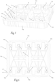
- a stack of trays 1 formed by means of a packaging system according to an embodiment of the present invention is illustrated in Figs 1 and 2 .
- the illustrated stack 1 comprises three trays 2 of the type illustrated in Figs 3-7 and one lid 3 of the type illustrated in Fig 8 , wherein the trays 2 are stacked on each other and positioned on a pallet 4 and wherein the lid 3 is positioned on top of the uppermost tray 2 in the stack 1.
- the stack 1 formed by the trays 2 and the lid 3 is secured to the pallet 4 by means of staps 6 of plastic or metallic material, which are applied around the lid 3 and the pallet 4 and thereafter tightened and joined together by means of any suitable type of strapping tool or strapping machine.
- each tray 2 is designed to accommodate four electric vehicle lithium-ion batteries (not shown), but the trays may of course also be designed to accommodate other types of products.
- the trays 2 may for instance have a length of 800-1200 mm, a width of 600-1000 mm and a height of 150-300 mm.
- Each tray 2 is of plastic material and produced by thermoforming, preferably from a sheet of plastic material having a thickness of 8-12 mm.
- Each tray 2 comprises a product supporting base 10, which has an upwardly facing upper side 10a and an opposite downwardly facing underside 10b.
- Each tray 2 also comprises sidewalls 11a-11d integrally formed with the base 10 and extending upwardly from the base 10 along the circumference thereof. The sidewalls 11a-11d are mutually connected to each other to form a collar or frame around the upper side 10a of the base 10.
- Each tray 2 is upwardly open, wherein the sidewalls 11a-11d of the tray together define an upper opening 12 of the tray.
- the base 10 and the sidewalls 11a-11d of the tray 2 together delimit an interior cavity 13 of the tray for receiving one or more products, wherein the upper side 10a of the base is facing this interior cavity 13.
- the interior cavity 13 of the tray 2 is open in vertical direction upwards and is delimited in vertical direction downwards by the base 10 of the tray and in lateral directions by the sidewalls 11a-11d of the tray.
- the interior cavity 13 of the tray is divided into two separate compartments by means of a partition 14 at the centre of the interior cavity 13, wherein two electric vehicle lithium-ion batteries are intended to be accommodated in each compartment.
- the partition 14 is integrally formed with the base 10 of the tray and extends upwardly from the base 10.
- the tray 2 fits onto each other such that two or more trays 2 may be stacked on each other to form a stack of trays.
- the base 10 of the upper tray is configured to cover the upper opening 12 of the lower tray.
- the trays 2 included in the packaging system are with advantage identically designed, but the packaging system could also comprise trays 2 of different designs as long as they are stackable on each other, i.e. as long as each tray 2 fits onto each one of the other trays with the base 10 of the tray covering the upper opening 12 of the other tray.
- the sidewalls of each tray 2 comprise two opposite and mutually parallel longer sidewalls 11a, 11b and two opposite and mutually parallel shorter sidewalls 11c, 11d, wherein the shorter sidewalls 11c, 11d extend perpendicularly to the longer sidewalls 11a, 11b.
- the corners 11e between each end of a longer sidewall 11a, 11b and the adjacent end of an adjacent shorter sidewall 11c, 11d may be bevelled, as illustrated in Figs 1-7 , or straight.
- each tray 2 is provided with an upper rim 15 that extends around the periphery of the upper opening 12 of the tray along the upper edges of the sidewalls 11a-11d and a lower rim 16 that extends around the periphery of the base 10 of the tray along the lower edges of the sidewalls 11a-11d.
- the lower rim 16 on each tray 2 is configured to mate with the upper rim 15 on each one of the other trays, such that the upper rim 15 on a first tray and the lower rim 16 on a second tray located on top of the first tray together form a seal that prevents dust and water from entering the interior cavity 13 of the first tray.
- the upper and lower rims 15, 16 are bevelled, but they could also have any other suitable shape.
- each tray 2 has an upwardly facing shoulder 17 that surround the upper rim 15 on the tray and a downwardly facing shoulder 18 that surround the lower rim 16 on the tray.
- the downwardly facing shoulder 18 on the upper tray is configured to abut against the upwardly facing shoulder 17 on the lower tray.
- the lid 3 is of plastic material and is preferably produced by thermoforming, for instance from a sheet of plastic material having a thickness of 8-12 mm.
- the lid 3 is configured to fit onto each one of the trays 2 such that is covers the upper opening 12 thereof and prevents dust and water from entering the interior cavity 13 of the tray.
- the lid 3 has an underside 3b that is configured to face a tray 2 when the lid is mounted onto the tray and an opposite upper side 3a.
- the packaging system further comprises several elongated support elements 5, preferably of plastic material.
- the support elements 5 are tubular and cylindrical and open at both ends.
- One of the tubular support elements 5 included in the embodiment of Figs 1-8 is shown in closer detail in Figs 9a and 9b .
- each support element 5 has a polygonal cross-sectional shape, as illustrated in Fig 9b .
- such tubular and cylindrical support elements 5 could also have a circular cross-sectional shape, as illustrated in Figs 10a and 10b .
- the support elements 5 could be formed as solid elements.
- the support elements 5 may have any suitable cross-sectional shape, such as for instance quadratic, as illustrated in Figs 11a and 12a , rectangular or triangular.
- the cross-sectional shape of each support element 5 is with advantage constant along the entire length of the support element, as illustrated in Figs 9a, 10a and 11a . In the variant illustrated in Fig 12a , there is a narrow waist between the two ends of the support element 5.
- first seats 21 adapted for connection to a respective one of the support elements 5 are provided on the upper side 10a of the base 10 of each tray 2.
- second seats 22 adapted for connection to a respective one of the support elements 5 are also provided on the underside 3b of the lid 3 in such positions that each one of these second seats 22 is vertically aligned with one of the first seats 21 on the upper side 10a of the base of a tray 2 when the lid 3 is mounted on top of the tray 2 with the lid 3 covering the upper opening 12 of the tray.
- each third seat 23 adapted for connection to a respective one of the support elements 5 are provided on the underside 10b of the base 10 of each tray 2 opposite to a respective one of the first seats 21 on the upper side 10a of the base 10.
- each third seat 23 on the underside 10b of a base of a tray 2 is located below and in vertical alignment with one of the first seats 21 on the upper side 10a of the base of the tray 2.
- Each support element 5 has a first end 5a that is adapted to mate with the first seats 21 on the upper side 10a of the base of each tray 2, and an opposite second end 5b that is adapted to mate with the second seats 22 on the underside 3b of the lid 3 and with the third seats 23 on the underside 10b of the base of each tray 2.
- the support elements 5 are vertically and detachably mountable to the first seats 21 of the trays 2 in order to extend in vertical direction through the interior cavity 13 of the trays with each individual support element 5 extending:
- first seats 21 on the upper side 10a of the base 10 of each tray 2 wherein a first group of five first seats 21 are arranged on the upper side of the base 10 along a first one 11a of the two longer sidewalls of the tray and a second group of five first seats 21 are arranged on the upper side of the base 10 in a second row along the other longer sidewall 11b of the tray.
- second seats 22 arranged in corresponding rows on the underside 3b of the lid 3
- the first and third seats 21, 23 on each tray 2, and the second seats 22 on the lid 3 may of course also be of any other suitable number and/or arranged in any other suitable manner.
- the first end 5a of each individual support element 5 has preferably the same design as the second end 5b of the support element, to thereby allow each support element 5 to be mounted with any of its two ends 5a, 5b facing the base 10 of the tray.
- both ends 5a, 5b of each support element 5 have to be adapted to mate with the first seats 21 on the upper side 10a of the base of each tray 2 and also with the second seats 22 on the underside 3b of the lid 3 and with the third seats 23 on the underside 10b of the base of each tray 2.
- the above-mentioned partition 14 has such a height that an upper part 14a of the partition 14 of a first tray 2 located immediately below a second tray in a stack 1 formed by two or more trays 2 is configured to be in contact with the underside 10b of the base 10 of the second tray to thereby allow the partition 14 of the first tray to provide support between the base 10 of the second tray and the base 10 of the first tray.
Landscapes
- Engineering & Computer Science (AREA)
- Mechanical Engineering (AREA)
- Stackable Containers (AREA)
- Packages (AREA)
Priority Applications (2)
| Application Number | Priority Date | Filing Date | Title |
|---|---|---|---|
| EP22181180.5A EP4299461A1 (de) | 2022-06-27 | 2022-06-27 | Verpackungssystem und verfahren zum verpacken von produkten unter verwendung eines verpackungssystems |
| DE202022103758.2U DE202022103758U1 (de) | 2022-06-27 | 2022-07-05 | Verpackungssystem |
Applications Claiming Priority (1)
| Application Number | Priority Date | Filing Date | Title |
|---|---|---|---|
| EP22181180.5A EP4299461A1 (de) | 2022-06-27 | 2022-06-27 | Verpackungssystem und verfahren zum verpacken von produkten unter verwendung eines verpackungssystems |
Publications (1)
| Publication Number | Publication Date |
|---|---|
| EP4299461A1 true EP4299461A1 (de) | 2024-01-03 |
Family
ID=82321303
Family Applications (1)
| Application Number | Title | Priority Date | Filing Date |
|---|---|---|---|
| EP22181180.5A Withdrawn EP4299461A1 (de) | 2022-06-27 | 2022-06-27 | Verpackungssystem und verfahren zum verpacken von produkten unter verwendung eines verpackungssystems |
Country Status (2)
| Country | Link |
|---|---|
| EP (1) | EP4299461A1 (de) |
| DE (1) | DE202022103758U1 (de) |
Families Citing this family (1)
| Publication number | Priority date | Publication date | Assignee | Title |
|---|---|---|---|---|
| CN117446328A (zh) * | 2023-11-13 | 2024-01-26 | 河北零点新能源科技有限公司 | 一种具有精准定位功能可调节的锂电池定量包装装置 |
Citations (4)
| Publication number | Priority date | Publication date | Assignee | Title |
|---|---|---|---|---|
| KR19980053561A (ko) * | 1996-12-27 | 1998-09-25 | 안기훈 | 음극선관용 패널 포장조립체 |
| EP2824035A1 (de) * | 2013-07-03 | 2015-01-14 | Feurer Febra GmbH | Transportvorrichtung |
| WO2020165662A1 (en) * | 2019-02-16 | 2020-08-20 | Upale Pravin | A modular crate assembly to eliminate master box in packaging |
| US20210107694A1 (en) * | 2019-10-10 | 2021-04-15 | P.R.A. Company, d/b/a Vantage Plastics | Reusable recyclable thermoformed shipping containers |
-
2022
- 2022-06-27 EP EP22181180.5A patent/EP4299461A1/de not_active Withdrawn
- 2022-07-05 DE DE202022103758.2U patent/DE202022103758U1/de not_active Expired - Lifetime
Patent Citations (4)
| Publication number | Priority date | Publication date | Assignee | Title |
|---|---|---|---|---|
| KR19980053561A (ko) * | 1996-12-27 | 1998-09-25 | 안기훈 | 음극선관용 패널 포장조립체 |
| EP2824035A1 (de) * | 2013-07-03 | 2015-01-14 | Feurer Febra GmbH | Transportvorrichtung |
| WO2020165662A1 (en) * | 2019-02-16 | 2020-08-20 | Upale Pravin | A modular crate assembly to eliminate master box in packaging |
| US20210107694A1 (en) * | 2019-10-10 | 2021-04-15 | P.R.A. Company, d/b/a Vantage Plastics | Reusable recyclable thermoformed shipping containers |
Also Published As
| Publication number | Publication date |
|---|---|
| DE202022103758U1 (de) | 2022-10-11 |
Similar Documents
| Publication | Publication Date | Title |
|---|---|---|
| CA2801514C (en) | Tri-fold egg carton for jumbo eggs | |
| US5344021A (en) | Molded crate with interlocking rim appliances | |
| US7163122B2 (en) | Container | |
| US3420402A (en) | Stackable and nestable container | |
| EP2130785B1 (de) | Zwischenlagenplatte | |
| EP3464095B1 (de) | Stapelbarer schüttgutbehälter | |
| EP0414480A1 (de) | Eine Kiste | |
| US20230227198A1 (en) | Reusable recyclable thermoformed shipping containers | |
| US20180273284A1 (en) | Tri-fold egg carton for various size jumbo eggs | |
| KR101023439B1 (ko) | 중량물 운송용 포장조립체 및 그의 포장체 | |
| US4311239A (en) | Television panel package | |
| EP4299461A1 (de) | Verpackungssystem und verfahren zum verpacken von produkten unter verwendung eines verpackungssystems | |
| US10227157B2 (en) | Egg carton with diagonal lid panel | |
| EP2780245A1 (de) | Verpackung mit einer schale mit einer gruppe von flanschbehälter | |
| US20220081158A1 (en) | Integrated tray and pallet system | |
| JP2011105319A (ja) | 梱包材とそれを用いた梱包体および梱包材の組立方法 | |
| US7503455B2 (en) | Cross-stacking container | |
| CA3141095C (en) | TWO-HANDLE EGG BOX | |
| US7070052B2 (en) | Packaging system for cathode ray tube components | |
| JP6691413B2 (ja) | 集合包装容器及びその積層体 | |
| EP2155569B1 (de) | Transportpalette für den transport mehrerer in folie gereifter käse | |
| US20050224386A1 (en) | Lightweight interlocking container | |
| WO2011103662A1 (en) | Pallets for holding panels | |
| CN213291305U (zh) | 吸塑托盘成型模具 | |
| MXPA04004861A (es) | Embalaje para el embarque de objetos apilables. |
Legal Events
| Date | Code | Title | Description |
|---|---|---|---|
| PUAI | Public reference made under article 153(3) epc to a published international application that has entered the european phase |
Free format text: ORIGINAL CODE: 0009012 |
|
| STAA | Information on the status of an ep patent application or granted ep patent |
Free format text: STATUS: THE APPLICATION HAS BEEN PUBLISHED |
|
| AK | Designated contracting states |
Kind code of ref document: A1 Designated state(s): AL AT BE BG CH CY CZ DE DK EE ES FI FR GB GR HR HU IE IS IT LI LT LU LV MC MK MT NL NO PL PT RO RS SE SI SK SM TR |
|
| STAA | Information on the status of an ep patent application or granted ep patent |
Free format text: STATUS: THE APPLICATION IS DEEMED TO BE WITHDRAWN |
|
| 18D | Application deemed to be withdrawn |
Effective date: 20240704 |