EP4299486A2 - Modulare kopfreinigungsvorrichtung und system - Google Patents
Modulare kopfreinigungsvorrichtung und system Download PDFInfo
- Publication number
- EP4299486A2 EP4299486A2 EP23167567.9A EP23167567A EP4299486A2 EP 4299486 A2 EP4299486 A2 EP 4299486A2 EP 23167567 A EP23167567 A EP 23167567A EP 4299486 A2 EP4299486 A2 EP 4299486A2
- Authority
- EP
- European Patent Office
- Prior art keywords
- cleaning head
- rotary
- cleaning
- rotary cleaning
- conveyor belt
- Prior art date
- Legal status (The legal status is an assumption and is not a legal conclusion. Google has not performed a legal analysis and makes no representation as to the accuracy of the status listed.)
- Pending
Links
- 238000004140 cleaning Methods 0.000 title claims abstract description 283
- 230000009471 action Effects 0.000 claims abstract description 30
- 230000008878 coupling Effects 0.000 claims abstract description 19
- 238000010168 coupling process Methods 0.000 claims abstract description 19
- 238000005859 coupling reaction Methods 0.000 claims abstract description 19
- 239000007788 liquid Substances 0.000 claims description 14
- 230000033001 locomotion Effects 0.000 claims description 13
- 238000000034 method Methods 0.000 claims description 9
- 239000000047 product Substances 0.000 description 17
- 230000007246 mechanism Effects 0.000 description 15
- 239000000463 material Substances 0.000 description 11
- 239000012530 fluid Substances 0.000 description 10
- 235000013305 food Nutrition 0.000 description 9
- 238000004519 manufacturing process Methods 0.000 description 9
- 239000004033 plastic Substances 0.000 description 6
- 229920003023 plastic Polymers 0.000 description 6
- 239000013566 allergen Substances 0.000 description 5
- 239000000356 contaminant Substances 0.000 description 5
- 241000251468 Actinopterygii Species 0.000 description 4
- 235000010469 Glycine max Nutrition 0.000 description 4
- 244000068988 Glycine max Species 0.000 description 4
- 241000209140 Triticum Species 0.000 description 4
- 235000021307 Triticum Nutrition 0.000 description 4
- 238000009825 accumulation Methods 0.000 description 4
- 230000035508 accumulation Effects 0.000 description 4
- 238000011109 contamination Methods 0.000 description 4
- 239000003814 drug Substances 0.000 description 4
- 239000000825 pharmaceutical preparation Substances 0.000 description 4
- 229940127557 pharmaceutical product Drugs 0.000 description 4
- 238000002360 preparation method Methods 0.000 description 4
- 235000015170 shellfish Nutrition 0.000 description 4
- 238000009987 spinning Methods 0.000 description 4
- 239000004615 ingredient Substances 0.000 description 3
- 239000002184 metal Substances 0.000 description 3
- 239000013618 particulate matter Substances 0.000 description 3
- 238000009428 plumbing Methods 0.000 description 3
- 239000000126 substance Substances 0.000 description 3
- 206010067484 Adverse reaction Diseases 0.000 description 2
- OKTJSMMVPCPJKN-UHFFFAOYSA-N Carbon Chemical compound [C] OKTJSMMVPCPJKN-UHFFFAOYSA-N 0.000 description 2
- 206010020751 Hypersensitivity Diseases 0.000 description 2
- 230000001464 adherent effect Effects 0.000 description 2
- 230000006838 adverse reaction Effects 0.000 description 2
- 230000007815 allergy Effects 0.000 description 2
- 230000000712 assembly Effects 0.000 description 2
- 238000000429 assembly Methods 0.000 description 2
- 239000007795 chemical reaction product Substances 0.000 description 2
- 230000006378 damage Effects 0.000 description 2
- 230000000694 effects Effects 0.000 description 2
- 230000007717 exclusion Effects 0.000 description 2
- 239000013568 food allergen Substances 0.000 description 2
- 230000006870 function Effects 0.000 description 2
- 239000000314 lubricant Substances 0.000 description 2
- 239000003973 paint Substances 0.000 description 2
- 230000000737 periodic effect Effects 0.000 description 2
- 230000035945 sensitivity Effects 0.000 description 2
- 238000010408 sweeping Methods 0.000 description 2
- 238000005406 washing Methods 0.000 description 2
- 208000012260 Accidental injury Diseases 0.000 description 1
- 241000894006 Bacteria Species 0.000 description 1
- 229910000831 Steel Inorganic materials 0.000 description 1
- 230000001154 acute effect Effects 0.000 description 1
- 239000003570 air Substances 0.000 description 1
- 230000008901 benefit Effects 0.000 description 1
- 230000033228 biological regulation Effects 0.000 description 1
- 229910052799 carbon Inorganic materials 0.000 description 1
- 230000001276 controlling effect Effects 0.000 description 1
- 238000012864 cross contamination Methods 0.000 description 1
- 230000001627 detrimental effect Effects 0.000 description 1
- 238000001035 drying Methods 0.000 description 1
- 239000004744 fabric Substances 0.000 description 1
- 239000012634 fragment Substances 0.000 description 1
- 239000010439 graphite Substances 0.000 description 1
- 229910002804 graphite Inorganic materials 0.000 description 1
- 208000014674 injury Diseases 0.000 description 1
- 238000002372 labelling Methods 0.000 description 1
- 230000005923 long-lasting effect Effects 0.000 description 1
- 230000014759 maintenance of location Effects 0.000 description 1
- 230000000116 mitigating effect Effects 0.000 description 1
- 239000003921 oil Substances 0.000 description 1
- 239000004417 polycarbonate Substances 0.000 description 1
- 229920000515 polycarbonate Polymers 0.000 description 1
- 229920000642 polymer Polymers 0.000 description 1
- 230000001105 regulatory effect Effects 0.000 description 1
- 239000007787 solid Substances 0.000 description 1
- 238000013020 steam cleaning Methods 0.000 description 1
- 239000010959 steel Substances 0.000 description 1
- 238000009966 trimming Methods 0.000 description 1
- XLYOFNOQVPJJNP-UHFFFAOYSA-N water Substances O XLYOFNOQVPJJNP-UHFFFAOYSA-N 0.000 description 1
Images




Classifications
-
- B—PERFORMING OPERATIONS; TRANSPORTING
- B65—CONVEYING; PACKING; STORING; HANDLING THIN OR FILAMENTARY MATERIAL
- B65G—TRANSPORT OR STORAGE DEVICES, e.g. CONVEYORS FOR LOADING OR TIPPING, SHOP CONVEYOR SYSTEMS OR PNEUMATIC TUBE CONVEYORS
- B65G45/00—Lubricating, cleaning, or clearing devices
- B65G45/10—Cleaning devices
- B65G45/22—Cleaning devices comprising fluid applying means
-
- B—PERFORMING OPERATIONS; TRANSPORTING
- B08—CLEANING
- B08B—CLEANING IN GENERAL; PREVENTION OF FOULING IN GENERAL
- B08B1/00—Cleaning by methods involving the use of tools
- B08B1/20—Cleaning of moving articles, e.g. of moving webs or of objects on a conveyor
-
- B—PERFORMING OPERATIONS; TRANSPORTING
- B08—CLEANING
- B08B—CLEANING IN GENERAL; PREVENTION OF FOULING IN GENERAL
- B08B1/00—Cleaning by methods involving the use of tools
- B08B1/30—Cleaning by methods involving the use of tools by movement of cleaning members over a surface
- B08B1/32—Cleaning by methods involving the use of tools by movement of cleaning members over a surface using rotary cleaning members
- B08B1/36—Cleaning by methods involving the use of tools by movement of cleaning members over a surface using rotary cleaning members rotating about an axis orthogonal to the surface
-
- B—PERFORMING OPERATIONS; TRANSPORTING
- B08—CLEANING
- B08B—CLEANING IN GENERAL; PREVENTION OF FOULING IN GENERAL
- B08B3/00—Cleaning by methods involving the use or presence of liquid or steam
- B08B3/02—Cleaning by the force of jets or sprays
- B08B3/022—Cleaning travelling work
-
- B—PERFORMING OPERATIONS; TRANSPORTING
- B08—CLEANING
- B08B—CLEANING IN GENERAL; PREVENTION OF FOULING IN GENERAL
- B08B3/00—Cleaning by methods involving the use or presence of liquid or steam
- B08B3/02—Cleaning by the force of jets or sprays
- B08B3/024—Cleaning by means of spray elements moving over the surface to be cleaned
-
- B—PERFORMING OPERATIONS; TRANSPORTING
- B08—CLEANING
- B08B—CLEANING IN GENERAL; PREVENTION OF FOULING IN GENERAL
- B08B5/00—Cleaning by methods involving the use of air flow or gas flow
- B08B5/02—Cleaning by the force of jets, e.g. blowing-out cavities
- B08B5/023—Cleaning travelling work
- B08B5/026—Cleaning moving webs
-
- D—TEXTILES; PAPER
- D21—PAPER-MAKING; PRODUCTION OF CELLULOSE
- D21F—PAPER-MAKING MACHINES; METHODS OF PRODUCING PAPER THEREON
- D21F1/00—Wet end of machines for making continuous webs of paper
- D21F1/32—Washing wire-cloths or felts
-
- B—PERFORMING OPERATIONS; TRANSPORTING
- B08—CLEANING
- B08B—CLEANING IN GENERAL; PREVENTION OF FOULING IN GENERAL
- B08B2230/00—Other cleaning aspects applicable to all B08B range
- B08B2230/01—Cleaning with steam
-
- B—PERFORMING OPERATIONS; TRANSPORTING
- B65—CONVEYING; PACKING; STORING; HANDLING THIN OR FILAMENTARY MATERIAL
- B65G—TRANSPORT OR STORAGE DEVICES, e.g. CONVEYORS FOR LOADING OR TIPPING, SHOP CONVEYOR SYSTEMS OR PNEUMATIC TUBE CONVEYORS
- B65G2207/00—Indexing codes relating to constructional details, configuration and additional features of a handling device, e.g. Conveyors
- B65G2207/30—Modular constructions
Definitions
- the present invention relates to systems and methods for surface cleaning, such as cleaning commercial conveyor belts as may be used, for example, in the continuous food preparation and baking arts; and more particularly to a conveyor belt cleaner system for detecting food allergens or chemicals and then employing a modular head cleaning mechanism to remove said known food allergens or chemicals that are often entrapped or ensnared on or in the conveyor belt during food preparation processing.
- Conveyors are widely used for conveying a variety of products, including discrete items or assemblies as well as bulk materials. In many instances some of the materials coming in contact with the conveyor will cling or adhere thereto. These materials may include product fines or trimmings, excess product, excess finishing materials, or extraneous materials from other sources such as accumulations of lubricants or dirt, may include adherent liquids such as paints, and may include debris from pharmaceutical products. All such materials are encompassed by the term "debris" hereinafter. The retention or accumulation of such debris on the conveyor usually is undesirable or unacceptable.
- a cleaning head capable of being directed to said debris would improve both the efficiency and effectiveness of a modular head resulting in less down time and increased product safety.
- conveyor belts used in various commercial activities are known to become soiled, typically with spillage from materials being conveyed or treated on the belt. It becomes desirable and necessary to clean at least the working upper surface of the belt.
- the need for such cleaning is heightened when for example food products, pharmaceuticals, and other indigestible items are the article of manufacture.
- the need is more crucial when the ultimate article of manufacture under preparation on the conveyor belt contains ingredients or components that if accidentally permitted to contaminate certain different articles of manufacture could result in harm and potentially death.
- the need is felt even more acutely when contaminates may not be visible to the naked eye.
- the problem of adherence and accumulation of debris typically is enhanced when the product being handled or the environment of use exposes the conveyor to oils, food toppings, lubricants, paints or other adherent materials.
- the cleaning requirements and problems referred to above are enhanced when dealing with food and pharmaceutical products because of the need to avoid contamination of the end products as well as to minimize or avoid the inclusion of product debris or fragments in the packages of the end product.
- Governmental regulations and desirable operating practices also typically require periodic complete washing and/or steam cleaning of equipment which contacts food or pharmaceutical products during production, with dismantling of relevant processing mechanisms for such cleaning.
- US Patent No. 7,784,476 to Handy discloses and claims a portable cleaning system for cleaning a moving item such as an escalator or conveyor belt.
- the system comprises an overhead steam jet assembly slidably mounted on transverse rails for motion transverse to the direction of motion of the escalator or conveyor belt.
- the transverse rails are disposed between width-adjustable end pieces that rest on stationary outer members of the escalator.
- a shortcoming of this system is that the steam jet assembly has no mechanism to direct the assembly to particular locations on the belt.
- US Patent No. 9,248,975 to Handy also discloses and claims a portable cleaning system for cleaning a moving item such as an escalator or conveyor belt.
- the system comprises an overhead steam jet assembly slidably mounted on transverse rails for motion transverse to the direction of motion of the escalator or conveyor belt.
- the transverse rails are disposed between width-adjustable end pieces that rest on stationary outer members of the escalator.
- a shortcoming of this system is that the steam jet assembly is that no mechanism exists to direct the assembly to particular locations on the belt.
- US Patent No. 10,150,623 to Handy discloses and claims a cleaning apparatus comprising a connection part permitting connection to a supply of cleaning fluid, and a rotatable member rotatably movable relative to the connection part, the rotatable member being in a form of a disc with an opening within the disc in connection with the connection part to receive cleaning fluid therefrom, with one or more outlets extending from the opening in the disc, to an exterior of the disc, to supply cleaning fluid to an area or item to be cleaned, wherein the rotatable member is made of a plastics material, and wherein the rotatable member is driven by a gear provided on the rotatable member and the gear is drivable by a motor.
- a shortcoming of this system is that the steam jet assembly is that no mechanism exists to direct the assembly to particular locations on the belt. Perhaps, the most significant drawback presented by the system is its failure to address the removal of certain particulates (e.g., whole, crushed, or fragmented seeds and nuts, soybean particulate, wheat debris, egg debris, and fish or shellfish remains), which may become embedded in the surface conveyor belts. Indeed, it is likely that the mechanism of the assembly claimed by the ⁇ 623 Patent would likely exacerbate these precise concerns.
- particulates e.g., whole, crushed, or fragmented seeds and nuts, soybean particulate, wheat debris, egg debris, and fish or shellfish remains
- US Patent No. 6,971,503 to Thompson discloses A conveyor belt cleaning apparatus for cleaning a continuous loop conveyor belt having a surface and within a check stand, comprising: a debris-removal stage; a washing stage; a rinsing stage; a drying stage; and a multi-chambered drawer and each of said stages is provided with an isolated bin within the drawer; wherein said surface of said continuous loop conveyor belt passes through said stages to remove any debris and bacteria.
- the steam jet assembly is that no mechanism exists to direct the assembly to particular locations on the belt.
- the desired conveyor belt cleaning system will provide a means for such manufacturers of food products, pharmaceuticals, and other ingestible goods, and most notably those that produce multiple types of products, where some of such products may contain various types of allergens or the like that could cause adverse reactions if ingested or used by unsuspected consumers prone to such allergies or sensitivities to prevent the accidental contamination of their other products manufactured using the same conveyor belt through the effective removal of such contaminants and allergens.
- the invention provides a cleaning apparatus including a rotary cleaning head for cleaning surfaces, the cleaning apparatus comprising: the rotary cleaning head capable of, or adapted for, performing a cleaning action on a surface, said rotary cleaning head comprising a rotating disc assembly; a mobile mount operational to move the rotary cleaning head into a first cleaning contact position with the surface; a connecting portion having a proximal end and a distal end wherein the proximal end includes a first coupling, said coupling capable of, or adapted for, making a connection to and disconnecting from the mobile mount, and said distal end capable of, or adapted for, making a connection and disconnecting from the rotary cleaning head and adapted for use with the rotary cleaning head; and a plurality of flanges proximally extending from the rotating disc assembly, wherein the flanges are capable of, or adapted for, creating an airflow which performs said cleaning action.
- the rotating disc assembly produces, or is adapted for producing, a thermally insulated pocket.
- the cleaning apparatus further comprises a plurality of cogs for driving the rotary cleaning head.
- the rotary cleaning head further comprises a removable spindle.
- the cleaning apparatus further comprises: a pump operably connected to the rotary cleaning head by a hose, said hose operable to cause a liquid or vapor under pressure to enter the rotary cleaning head; wherein the rotary cleaning head directs the liquid or vapor under pressure to the upper belt to produce a cleaning action on the surface.
- the invention provides a system that utilizes a rotary cleaning head for cleaning an endless conveyor belt comprising: the rotary cleaning head capable of, or adapted for, performing a cleaning action on a first section of the endless conveyor belt, wherein the rotary cleaning head further comprises a removable spindle; a mobile mount operational to move the rotary cleaning head into a first cleaning contact position with the endless conveyor belt; a connecting portion having a proximal end and a distal end wherein the proximal end includes a first coupling, said coupling capable of, or adapted for, making a connection to and disconnecting from the mobile mount, and said distal end capable of, or adapted for, making a connection and disconnecting from the rotary cleaning head and adapted for use with the rotary cleaning head; and a first reservoir capable of, or adapted for, attaching to the system and configured to deliver a first medium to the endless conveyor.
- the rotary cleaning head further comprises a plurality of fan blades operable to increase a pressure in a steam.
- the rotating cleaning head further comprises a plurality of flanges proximally extending from the disc, wherein the flanges are capable of, or adapted for, creating an airflow, and wherein said airflow performs said cleaning action.
- the rotating cleaning head produces, or is adapted for producing, a thermally insulated pocket.
- system further comprises a plurality of cogs for driving the rotary cleaning head.
- system further comprises: a pump operably connected to the rotary cleaning head by a hose, said hose operable to cause a liquid or vapor under pressure to enter the rotary cleaning head, wherein the rotary cleaning head directs, or is adapted for directing, the liquid or vapor under pressure to the upper belt to produce a cleaning action on said conveyor belt.
- the rotary cleaning head further comprises a plurality of fan blades operable to increase a pressure in a steam.
- the rotary cleaning head further comprises a rotating disc assembly.
- the invention provides a method for cleaning an endless conveyor belt using a rotary cleaning head comprising: attaching the rotary cleaning head capable of, or adapted for, performing a cleaning action on a first section of the endless conveyor belt to a distal end of a connecting portion, said rotary cleaning head comprising a rotating disc assembly; attaching the connecting portion to a first coupling of the mobile mount; moving the rotary cleaning head into a first cleaning contact position with the endless conveyor belt by use of the mobile mount; performing a cleaning action on a first section of the endless conveyor belt; and directing, by a plurality of fan blades, pressurized steam into cleaning contact with the conveyor belt.
- the rotary cleaning head further comprises a removable spindle.
- the method further comprises: attaching a pump to the rotary cleaning head by a hose, said hose operable to cause a liquid or vapor under pressure to enter the rotary cleaning head; directing the liquid or vapor under pressure to the upper belt to produce a cleaning action on said conveyor belt.
- the invention provides a modular cleaning head, comprising: a rotary disc configured to clean surfaces while engaging in a rotational movement; a deflector plate positioned above the rotary disc on a side opposite a surface that that rotary disc cleans; and fan blades attached to the rotary disc, in which the fans are positioned above the rotary disc and are adjacent to a bottom surface of the deflector plate.
- the fan blades extend from a central region of the rotary disc to a radial end of the rotary disc, preferably wherein the fan blades are at least partially curved.
- a laterally extending air shield may be developed which prevents or reduces debris from engaging with the rotary cleaning head during cleaning operations.
- the rotary disc is polygonal-shaped, preferably wherein the rotary disc is decagon shaped.
- the modular cleaning head further comprises a connecting bar that connects to an external structure, preferably wherein the connecting bar is substantially horizontal.
- the modular cleaning head further comprises a motor, preferably wherein the motor imparts drive from a drive chain to an adjacently-positioned cog and pulley arrangement which translates the drive to the rotary disc.
- the motor preferably is part of a frame of the rotary cleaning head.
- the invention provides a cleaning apparatus, e.g. in accordance with the cleaning apparatus according to the first aspect, which is configured with a cleaning head for cleaning an endless conveyor belt.
- the cleaning apparatus operates with a rotary cleaning head to perform a cleaning action on a first section of the endless conveyor belt.
- the rotary cleaning head comprises a rotating disc assembly.
- the rotary cleaning assembly is operable for a mobile mount to position the rotary cleaning head into a first cleaning contact position with the endless conveyor belt.
- a connecting portion having a proximal end and a distal end, wherein the proximal end includes a first coupling is provided.
- Said coupling is capable of making a connection to and disconnecting from the mobile mount, and said distal end capable of making a connection and disconnecting from the rotary cleaning head and adapted for use with the rotary cleaning head.
- the invention provides a cleaning system, e.g. in accordance with the system according to the second aspect, that employs a cleaning head for an endless conveyor belt is provided.
- the cleaning system is operable for a rotary cleaning head to performing a cleaning action on a first section of the endless conveyor belt.
- the rotary cleaning system is operable for a mobile mount to position the rotary cleaning head into a first cleaning contact position with the endless conveyor belt.
- a connecting portion having a proximal end and a distal end wherein the proximal end includes a first coupling is provided.
- Said coupling is capable of making a connection to and disconnecting from the mobile mount, and said distal end capable of making a connection and disconnecting from the rotary cleaning head and adapted for use with the rotary cleaning head.
- the rotary cleaning head further comprises a removable spindle.
- a pump is attached to the rotary cleaning head and is operable to cause a liquid or vapor under pressure to enter the rotary cleaning head.
- the invention provides a method for cleaning an endless conveyor using a cleaning head, e.g. in accordance with the method of the third aspect.
- a rotary cleaning head capable of performing a cleaning action on a first section of the endless conveyor belt is attached to a distal end of a connecting portion.
- a connecting portion is attached to a first coupling of the mobile mount.
- the rotary cleaning head is moved into a first cleaning contact position with the endless conveyor belt by use of the mobile mount; and a cleaning action is performed on a first section of the endless conveyor belt.
- a single cleaning head is shown, in some implementations, there may be multiple cleaning heads utilized for a single conveyor belt to improve cleaning of the conveyor belts and reduce wear and tear on a given cleaning head unit.
- the invention provides modular cleaning head, e.g. in accordance with the modular cleaning head according to the fourth aspect, comprising: a rotary disc configured to clean surfaces while engaging in a rotational movement; a deflector plate positioned above the rotary disc on a side opposite a surface that that rotary disc cleans; and fan blades attached to the rotary disc, in which the fans are positioned above the rotary disc and are adjacent to a bottom surface of the deflector plate.
- the fan blades extend from a central region of the rotary disc to a radial end of the rotary disc.
- the fan blades are at least partially curved.
- a laterally extending air shield is developed which prevents or reduces debris from engaging with the rotary cleaning head during cleaning operations.
- the rotary disc is polygonal-shaped.
- the rotary disc is decagon shaped.
- the connecting bar is substantially horizontal.
- a motor that is part of the rotary cleaning head's frame.
- the motor imparts drive from a drive chain to an adjacently-positioned cog and pulley arrangement which translates the drive to the rotary disc.
- system of the second or sixth aspect may make use of a modular cleaning head according to the fourth or eight aspect as the rotary cleaning head.
- method according to the third or seventh aspect may make use of a modular cleaning head according to the fourth or eight aspect as the rotary cleaning head.
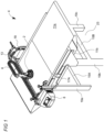
- a modular cleaning head 2 is shown with respect to the cleaning system 4.
- the modular cleaning head 2 is disposed above a conveyor belt 11 of the cleaning system and is operable to provide a cleaning action to the conveyor belt 11 having an upper conveyor belt 11a and lower conveyor belt 11b.
- a single cleaning head is shown, in some implementations, there may be multiple cleaning heads utilized for a single conveyor belt to improve cleaning of the conveyor belts and reduce wear an tear on a given cleaning head unit.
- Any additional cleaning heads may be configured similarly to the original cleaning head and utilize their own set of components that are attached to the frame, such as a separate connection points or other components necessary to operate the additional unit.
- the modular cleaning head 2 is operable to receive a variety of cleaning heads and is capable of dispensing chemicals, air, water or steam by a plurality of nozzles.
- the modular cleaning head is configured to provide a cleaning action to the belt 11 either by directly contacting the belt or by causing a medium, such as steam, to contact the belt. Said contact thereby generating a cleaning action removing particulates and debris.
- the modular cleaning head 2 is easily replaceable and can have a variety of configurations.
- a rotary cleaning head 16 can be used as the modular cleaning head 2.
- the modular cleaning head 2 could comprise a rotary or oscillating brush arrangement, the brushes removing particulate matter from the belt 11 by a cleaning action by contacting the belt 11.
- Both the modular cleaning head 2 and conveyor belt 11 are supported by a base assembly 23 including a plurality of transverse 15(a-b), longitudinal 17 and vertical 19(a-c) struts forming a rectangular assembly supporting a conveyor belt 11 and a frame 13 on which the modular cleaning head 2 is mounted.
- An adjustable end frame 18 affixes the frame 13 to the conveyor belt 11.
- a wire carriage 6 affixed to the modular cleaning head 2 is operative to cause the modular cleaning head 2 to move transversely to the belt 11.
- the wire carriage may be considered a mobile mount to which the modular cleaning head is attached and causes movement thereof.
- the wire carriage 6 is operable to move transverse to the direction of the belt 11, for example, by means of a gear, pulley or motor assembly utilizing a flange mated to a groove, said movement thereby causing the modular cleaning head 2 to correspondingly move transversely.
- the mobile mount, or wire carriage 6, can cause the modular cleaning head to move in various positions transversely across the conveyor belt, longitudinally with the conveyor belt, or rotationally, during operation.
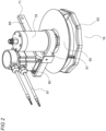
- Fig. 2 shows a rotary cleaning head 16 of the modular cleaning head 2.
- a rotary disc assembly 63 is driven by mechanical means by a motor 60.
- a plurality of motor control wires 67 by an electronic connection with the rotary disc assembly 63, powers and adjusts the speed of the rotary disc assembly 63.
- the rotary cleaning head 16 attaches to the wire carriage 6 by a connecting bar 69 which functions as a connecting portion that is affixed to the wire carriage 6 at a fastening point 71.
- a screw, bolt, or other fastening mechanism may attach the connecting bar's fastening point 71 to the wire carriage 6.
- a connection element or plate may be attached to the wire carriage 6 and, upon the connecting bar 69 being attached to the connection element or plate, translates to movement of the rotary cleaning head 16.
- a rotary union 79 also affixes the cleaning head 16 to wire carriage 6.
- a drive train cover 91 and air guide finger guard 95, or deflector plate, prevent both particulate matter from entering the cleaning head 16 and accidental injury by an operator.
- the finger guard 95 which also functions as a deflector plate as discussed below, is positioned above the spinning rotary cleaning head 16 to mitigate potential safety hazards associated with the spinning fins 83 ( FIGs. 3 and 4 ). Configurations in which the space between the solid finger guard 95 (not including the center air inlet) and the spinning rotary cleaning head 16 is minimized can increase the amount of lateral airflow that is generated by the spinning fan blades 83. This lateral airflow can provide an air shield to minimize debris from the cleaned surface traveling upward and settling on the cleaning head. In this regard, the finger guard 95 may have an effect on airflow at certain rotational speeds, thereby functioning as a deflector plate as well.
- the rotary disc assembly 63 comprises a rotary disc 80, as shown in Figs. 3 and 4 .
- the rotary disc 80 rotates in a clockwise rotation 85 around an axis.
- the rotary disc 80 is decagon-shaped - as opposed to being completely rounded - to enable deflection or mitigating direct impact with inbound obstacles. This minimizes damage to the cleaning head and downtime associated with clearing jammed conveyors.
- a decagon shape is depicted, other polygonal shapes are also possible, such as triangular, rectangular, hexagonal, etc.
- a plurality of fan blades 83, or fins, cause a centrifugally generated air curtain between the top of the rotary disc and the surface being cleaned, thereby keeping steam close to the belt 11, partially containing the force and heat of the steam on the belt 11, thereby generating a cleaning action on the belt 11.
- the fan blades 83 on the rotating surface are used to minimize debris accumulation on nearby surfaces, which may be due to lateral airflow. The use of the fan blades may be of particular benefit to industries where it is desirable to mitigate surface contamination.
- a plurality of impact points 82 disposed along the circumference of the rotary disc 80 impact and remove potential obstructions on the belt 11.
- the steam tube 113 is easily removable allowing for easy replacement.
- the steam tube may be press-fitted to the remainder of the tube, or utilize other fastening mechanisms, such as tab and notch, etc.
- a plurality of fan blades 83 force excess steam into contact with the belt 11, thereby causing a cleaning action.
- a thermally insulating pocket 120 in the disc minimizes heat loss through tube walls.
- Fig. 5 shows a path for air flow, indicated by arrow A.
- the modular cleaning head 2 with the rotary cleaning head 16 is removable from the wire carriage 6 and affixed in place by the connecting bar 69 ( FIG 2 ) mated to a rectangular hole 140, fastened with a clevis pin 130 and tethered 150 to the carriage/dolly 135.
- the clevis pin 130 can be manually removed by an operator allowing for removal of rotary cleaning head 16.
- Figs. 9 and 10 are the slide plates 78a, b.
- slide plates 78(a,b) are shown at a maximum width for accommodating the belt 11. Slide plates can be adjusted to accommodate a narrower belt 11 as shown in Fig. 10 .
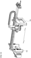
- Figs. 11-13 show an embodiment of the invention using a fluid or vapor to clean the belt 11.
- the fluid or vapor under pressure is input to a fluid connection 155.
- the fluid or vapor then travels along a flexible hose 157 disposed along the wire carriage 6 to the rotary cleaning head 16.
- steam under pressure is fed into the rotary cleaning head 16 by a spindle 108.
- the steam is then redirected at a hub 160 into the steam tubes 113 exiting at a plurality of nozzles 170.
- two first nozzles 115 are 90 degrees to the horizontal and two second nozzles 117 are 70 degrees to the horizontal.
- the tubes may be comprised of steel, graphite, plastic, carbon, and any other polymer to effectuate the purposes herein. This delivers greater cleaning power and reduced moisture content to surfaces relative to at least some other designs. For example, the increased efficiency of steam or fluid delivery is due to the gradual sweeping curvature of the tube instead of an abrupt 90° angle that can reduce cleaning power. While metal is typically utilized due to its long-lasting properties, other products may also be used, such as plastic, since metal may conduct heat away from the steam.
- a cleaning apparatus for an endless conveyor belt is provided.
- the cleaning apparatus is operable for a rotary cleaning head to perform a cleaning action on a first section of the endless conveyor belt.
- the rotary cleaning head comprises a rotating disc assembly.
- the rotary cleaning assembly is operable for a mobile mount to position the rotary cleaning head into a first cleaning contact position with the endless conveyor belt.
- a connecting portion having a proximal end and a distal end, wherein the proximal end includes a first coupling is provided.
- Said coupling is capable of making a connection to and disconnecting from the mobile mount, and said distal end capable of making a connection and disconnecting from the rotary cleaning head and adapted for use with the rotary cleaning head.
Landscapes
- Engineering & Computer Science (AREA)
- Mechanical Engineering (AREA)
- Cleaning In General (AREA)
- Structure Of Belt Conveyors (AREA)
- Spinning Or Twisting Of Yarns (AREA)
- Control Of Conveyors (AREA)
- Escalators And Moving Walkways (AREA)
- Cleaning By Liquid Or Steam (AREA)
Applications Claiming Priority (4)
| Application Number | Priority Date | Filing Date | Title |
|---|---|---|---|
| US17/658,835 US11565888B1 (en) | 2022-04-12 | 2022-04-12 | Modular head cleaning device and system |
| US17/805,723 US11661288B1 (en) | 2022-04-12 | 2022-06-07 | Conveyor belt cleaning device controllable by a control panel |
| US17/805,727 US11667475B1 (en) | 2022-04-12 | 2022-06-07 | Conveyor belt cleaning device having modularity and real-time cleaning adjustments based on sensory input |
| US17/805,722 US11618635B1 (en) | 2022-04-12 | 2022-06-07 | Conveyor belt cleaning device adapted with modular cleaning heads |
Publications (2)
| Publication Number | Publication Date |
|---|---|
| EP4299486A2 true EP4299486A2 (de) | 2024-01-03 |
| EP4299486A3 EP4299486A3 (de) | 2024-04-03 |
Family
ID=86006503
Family Applications (4)
| Application Number | Title | Priority Date | Filing Date |
|---|---|---|---|
| EP23167577.8A Pending EP4260956A1 (de) | 2022-04-12 | 2023-04-12 | Durch eine schalttafel steuerbare förderbandreinigungsvorrichtung |
| EP23167578.6A Pending EP4261160A1 (de) | 2022-04-12 | 2023-04-12 | Förderbandreinigungsvorrichtung mit modularität und echtzeit-reinigungsanpassungen auf basis der sensorischen eingabe |
| EP23167567.9A Pending EP4299486A3 (de) | 2022-04-12 | 2023-04-12 | Modulare kopfreinigungsvorrichtung und system |
| EP23167576.0A Withdrawn EP4299487A3 (de) | 2022-04-12 | 2023-04-12 | Förderbandreinigungsvorrichtung mit modularen reinigungsköpfen |
Family Applications Before (2)
| Application Number | Title | Priority Date | Filing Date |
|---|---|---|---|
| EP23167577.8A Pending EP4260956A1 (de) | 2022-04-12 | 2023-04-12 | Durch eine schalttafel steuerbare förderbandreinigungsvorrichtung |
| EP23167578.6A Pending EP4261160A1 (de) | 2022-04-12 | 2023-04-12 | Förderbandreinigungsvorrichtung mit modularität und echtzeit-reinigungsanpassungen auf basis der sensorischen eingabe |
Family Applications After (1)
| Application Number | Title | Priority Date | Filing Date |
|---|---|---|---|
| EP23167576.0A Withdrawn EP4299487A3 (de) | 2022-04-12 | 2023-04-12 | Förderbandreinigungsvorrichtung mit modularen reinigungsköpfen |
Country Status (2)
| Country | Link |
|---|---|
| EP (4) | EP4260956A1 (de) |
| AU (3) | AU2023202167A1 (de) |
Families Citing this family (3)
| Publication number | Priority date | Publication date | Assignee | Title |
|---|---|---|---|---|
| CN117324343A (zh) * | 2023-11-30 | 2024-01-02 | 宁德时代新能源科技股份有限公司 | 清洗系统、清洗系统的使用方法及电池的生产方法 |
| DE102024117932A1 (de) * | 2024-06-25 | 2026-01-08 | Krones Aktiengesellschaft | Vorrichtung zum Fördern von Behältern und zugehöriges Betriebsverfahren |
| GB2643710A (en) * | 2024-08-28 | 2026-03-04 | Industrial Packaging Solutions Ltd | Corrugator belt cleaning assembly, system comprising the same, and method of use of the cleaning assembly |
Citations (4)
| Publication number | Priority date | Publication date | Assignee | Title |
|---|---|---|---|---|
| US6971503B2 (en) | 2003-11-26 | 2005-12-06 | Cynthia Thompson | Conveyor belt cleaning apparatus |
| US7784476B2 (en) | 2004-03-12 | 2010-08-31 | Keith David Handy | Portable conveyor cleaning assembly |
| US9248975B2 (en) | 2012-11-12 | 2016-02-02 | Keith David Handy | Cleaning apparatus |
| US10150623B2 (en) | 2016-06-16 | 2018-12-11 | Keith David Handy | Cleaning apparatus |
Family Cites Families (12)
| Publication number | Priority date | Publication date | Assignee | Title |
|---|---|---|---|---|
| US4047666A (en) * | 1975-06-18 | 1977-09-13 | Bernard Eaton Hart | Jet or spray producing apparatus |
| FR2600918B1 (fr) * | 1986-07-04 | 1990-11-16 | Adam Michel | Appareil et procede pour laver le plateau de sechage d'un sechoir-tunnel |
| FR2604199B1 (fr) * | 1986-09-18 | 1988-12-09 | Technopap | Nettoyeur de bande continue permeable aux fluides en defilement, en particulier nettoyeur de toile pour machine a papier, et machines equipees d'un tel nettoyeur. |
| GB8903357D0 (en) * | 1989-02-14 | 1989-04-05 | Morley Michael J | Improvements in and relating to shower installations for paper making machines |
| RU2104357C1 (ru) * | 1995-12-25 | 1998-02-10 | Научно-производственное предприятие "АСК Бифор" | Автоматизированная система кондиционирования сукон бумагоделательных машин |
| JP3847164B2 (ja) * | 2001-12-26 | 2006-11-15 | 大浩研熱株式会社 | 回転波動ノズル |
| US7367443B2 (en) * | 2004-11-24 | 2008-05-06 | Martin Engineering Company | Conveyor belt cleaner system and method of manufacturing same |
| DE102005055988A1 (de) * | 2005-11-24 | 2007-05-31 | Voith Patent Gmbh | Reinigungsverfahren und Vorrichtung |
| DE102016000387A1 (de) * | 2015-12-21 | 2017-06-22 | F.E. Schulte Strathaus GmbH & Co. KG Fördertechnik Dichtungssysteme | Verfahren zum Regeln der Arbeitsweise einer Abstreifvorrichtung an einem Förderband |
| GB2567616B (en) * | 2017-09-15 | 2022-11-16 | David Handy Keith | Treatment method |
| JP6755563B1 (ja) * | 2019-09-06 | 2020-09-16 | イースタン技研株式会社 | エアノズル |
| CN111633658B (zh) * | 2020-06-08 | 2021-06-25 | 湖南翰坤实业有限公司 | 一种机械臂和围档清洗设备 |
-
2023
- 2023-04-08 AU AU2023202167A patent/AU2023202167A1/en active Pending
- 2023-04-08 AU AU2023202168A patent/AU2023202168A1/en active Pending
- 2023-04-08 AU AU2023202166A patent/AU2023202166A1/en active Pending
- 2023-04-12 EP EP23167577.8A patent/EP4260956A1/de active Pending
- 2023-04-12 EP EP23167578.6A patent/EP4261160A1/de active Pending
- 2023-04-12 EP EP23167567.9A patent/EP4299486A3/de active Pending
- 2023-04-12 EP EP23167576.0A patent/EP4299487A3/de not_active Withdrawn
Patent Citations (4)
| Publication number | Priority date | Publication date | Assignee | Title |
|---|---|---|---|---|
| US6971503B2 (en) | 2003-11-26 | 2005-12-06 | Cynthia Thompson | Conveyor belt cleaning apparatus |
| US7784476B2 (en) | 2004-03-12 | 2010-08-31 | Keith David Handy | Portable conveyor cleaning assembly |
| US9248975B2 (en) | 2012-11-12 | 2016-02-02 | Keith David Handy | Cleaning apparatus |
| US10150623B2 (en) | 2016-06-16 | 2018-12-11 | Keith David Handy | Cleaning apparatus |
Also Published As
| Publication number | Publication date |
|---|---|
| EP4299486A3 (de) | 2024-04-03 |
| AU2023202166A1 (en) | 2023-10-26 |
| EP4299487A2 (de) | 2024-01-03 |
| EP4299487A3 (de) | 2024-01-17 |
| AU2023202167A1 (en) | 2023-10-26 |
| EP4260956A1 (de) | 2023-10-18 |
| AU2023202168A1 (en) | 2023-10-26 |
| EP4261160A1 (de) | 2023-10-18 |
Similar Documents
| Publication | Publication Date | Title |
|---|---|---|
| EP4299486A2 (de) | Modulare kopfreinigungsvorrichtung und system | |
| US11565888B1 (en) | Modular head cleaning device and system | |
| US11821567B2 (en) | Cleaning assembly for a tubular drag conveyor | |
| US12102277B2 (en) | Pan cleaning system and improved cleaning stations | |
| KR101614534B1 (ko) | 벨트 컨베이어의 이물질 제거장치 | |
| GB2491127A (en) | Cleaning apparatus comprising drum and rollers. | |
| KR940001615B1 (ko) | 분말 용착장치 | |
| CN105980271A (zh) | 输送链支撑件 | |
| EP3921254B1 (de) | Kettenreinigungsmodul, förderer mit einem solchen kettenreinigungsmodul und verfahren zum reinigen einer förderkette | |
| US2012655A (en) | Fruit cleaning machine | |
| KR101606018B1 (ko) | 패널의 이물질제거장치 | |
| CN216971056U (zh) | 一种皮带机头清扫器 | |
| WO2024060957A1 (zh) | 一种输送机用落料清理机器人 | |
| US4235293A (en) | Self-cleaning fan housing | |
| US11358804B1 (en) | Apparatus and method for cleaning bidirectional food conveyor belt | |
| CN114906575A (zh) | 一种皮带输送机清扫除尘系统 | |
| GB2521889A (en) | A cleaning apparatus | |
| KR101414685B1 (ko) | 스낵용 감자 절단장치 | |
| KR102044316B1 (ko) | 스트립 방향전환 롤 표면의 이물질 제거장치 | |
| CN104755395B (zh) | 用于输送机皮带的锥形刮板 | |
| GB2491123A (en) | Air filtration system | |
| CN216835826U (zh) | 一种皮带清洁机构及皮带传输装置 | |
| US3075214A (en) | Apparatus for cleaning fruit such as berries and the like | |
| GB2079337A (en) | Wool cleaning apparatus | |
| EP2603443B1 (de) | Reinigungssystem vor ort für flachriemen |
Legal Events
| Date | Code | Title | Description |
|---|---|---|---|
| PUAI | Public reference made under article 153(3) epc to a published international application that has entered the european phase |
Free format text: ORIGINAL CODE: 0009012 |
|
| STAA | Information on the status of an ep patent application or granted ep patent |
Free format text: STATUS: THE APPLICATION HAS BEEN PUBLISHED |
|
| AK | Designated contracting states |
Kind code of ref document: A2 Designated state(s): AL AT BE BG CH CY CZ DE DK EE ES FI FR GB GR HR HU IE IS IT LI LT LU LV MC ME MK MT NL NO PL PT RO RS SE SI SK SM TR |
|
| RIC1 | Information provided on ipc code assigned before grant |
Ipc: B08B 5/02 20060101ALI20231208BHEP Ipc: B08B 3/02 20060101ALI20231208BHEP Ipc: B08B 1/04 20060101ALI20231208BHEP Ipc: B08B 1/02 20060101ALI20231208BHEP Ipc: D21F 1/32 20060101ALI20231208BHEP Ipc: B65G 45/22 20060101AFI20231208BHEP |
|
| PUAL | Search report despatched |
Free format text: ORIGINAL CODE: 0009013 |
|
| AK | Designated contracting states |
Kind code of ref document: A3 Designated state(s): AL AT BE BG CH CY CZ DE DK EE ES FI FR GB GR HR HU IE IS IT LI LT LU LV MC ME MK MT NL NO PL PT RO RS SE SI SK SM TR |
|
| RIC1 | Information provided on ipc code assigned before grant |
Ipc: B08B 5/02 20060101ALI20240229BHEP Ipc: B08B 3/02 20060101ALI20240229BHEP Ipc: B08B 1/04 20060101ALI20240229BHEP Ipc: B08B 1/02 20060101ALI20240229BHEP Ipc: D21F 1/32 20060101ALI20240229BHEP Ipc: B65G 45/22 20060101AFI20240229BHEP |
|
| STAA | Information on the status of an ep patent application or granted ep patent |
Free format text: STATUS: REQUEST FOR EXAMINATION WAS MADE |
|
| 17P | Request for examination filed |
Effective date: 20241003 |
|
| RBV | Designated contracting states (corrected) |
Designated state(s): AL AT BE BG CH CY CZ DE DK EE ES FI FR GB GR HR HU IE IS IT LI LT LU LV MC ME MK MT NL NO PL PT RO RS SE SI SK SM TR |
|
| STAA | Information on the status of an ep patent application or granted ep patent |
Free format text: STATUS: EXAMINATION IS IN PROGRESS |
|
| 17Q | First examination report despatched |
Effective date: 20241211 |