EP4299853A1 - Profilé de parement de bordure - Google Patents
Profilé de parement de bordure Download PDFInfo
- Publication number
- EP4299853A1 EP4299853A1 EP22181647.3A EP22181647A EP4299853A1 EP 4299853 A1 EP4299853 A1 EP 4299853A1 EP 22181647 A EP22181647 A EP 22181647A EP 4299853 A1 EP4299853 A1 EP 4299853A1
- Authority
- EP
- European Patent Office
- Prior art keywords
- leg member
- trim
- tiles
- edge trimming
- angled
- Prior art date
- Legal status (The legal status is an assumption and is not a legal conclusion. Google has not performed a legal analysis and makes no representation as to the accuracy of the status listed.)
- Withdrawn
Links
- 238000009966 trimming Methods 0.000 title claims abstract description 127
- 125000006850 spacer group Chemical group 0.000 claims abstract description 131
- 230000002093 peripheral effect Effects 0.000 claims abstract description 62
- 239000011440 grout Substances 0.000 claims abstract description 14
- 230000000153 supplemental effect Effects 0.000 claims description 15
- 229910001369 Brass Inorganic materials 0.000 claims description 3
- 239000004411 aluminium Substances 0.000 claims description 3
- 229910052782 aluminium Inorganic materials 0.000 claims description 3
- XAGFODPZIPBFFR-UHFFFAOYSA-N aluminium Chemical compound [Al] XAGFODPZIPBFFR-UHFFFAOYSA-N 0.000 claims description 3
- 239000010951 brass Substances 0.000 claims description 3
- 239000002131 composite material Substances 0.000 claims description 3
- 239000002184 metal Substances 0.000 claims description 3
- 229910052751 metal Inorganic materials 0.000 claims description 3
- 229920000642 polymer Polymers 0.000 claims description 3
- 229910001220 stainless steel Inorganic materials 0.000 claims description 3
- 239000010935 stainless steel Substances 0.000 claims description 3
- 239000004570 mortar (masonry) Substances 0.000 description 8
- 230000000694 effects Effects 0.000 description 3
- 230000015572 biosynthetic process Effects 0.000 description 2
- 239000000919 ceramic Substances 0.000 description 2
- 239000000463 material Substances 0.000 description 2
- 230000001419 dependent effect Effects 0.000 description 1
- 238000012986 modification Methods 0.000 description 1
- 230000004048 modification Effects 0.000 description 1
Images












Classifications
-
- E—FIXED CONSTRUCTIONS
- E04—BUILDING
- E04F—FINISHING WORK ON BUILDINGS, e.g. STAIRS, FLOORS
- E04F19/00—Other details of constructional parts for finishing work on buildings
- E04F19/02—Borders; Finishing strips, e.g. beadings; Light coves
- E04F19/06—Borders; Finishing strips, e.g. beadings; Light coves specially designed for securing panels or masking the edges of wall- or floor-covering elements
- E04F19/061—Borders; Finishing strips, e.g. beadings; Light coves specially designed for securing panels or masking the edges of wall- or floor-covering elements used to finish off an edge or corner of a wall or floor covering area
-
- E—FIXED CONSTRUCTIONS
- E04—BUILDING
- E04F—FINISHING WORK ON BUILDINGS, e.g. STAIRS, FLOORS
- E04F19/00—Other details of constructional parts for finishing work on buildings
- E04F19/02—Borders; Finishing strips, e.g. beadings; Light coves
- E04F19/06—Borders; Finishing strips, e.g. beadings; Light coves specially designed for securing panels or masking the edges of wall- or floor-covering elements
- E04F19/062—Borders; Finishing strips, e.g. beadings; Light coves specially designed for securing panels or masking the edges of wall- or floor-covering elements used between similar elements
- E04F19/064—Borders; Finishing strips, e.g. beadings; Light coves specially designed for securing panels or masking the edges of wall- or floor-covering elements used between similar elements in corners
Definitions
- the present invention generally relates to an edge trimming profile for finishing of a peripheral edge of at least one set of one or more tiles of a floor or wall covering.
- Edge trimming profiles are known in the art and widely used to finish the peripheral edges of sets of tiles (especially ceramic tiles) of floor and wall coverings.
- British Patent No. GB 2 203 996 B discloses an edge trimming profile designed to fill the gap between the ends of two panels or tiles forming an outwardly facing corner.
- the edge trimming profile comprises a pair of oppositely facing base leg members, or webs, connected to a contoured corner in-fill section.
- the base leg members are spaced below the level of the outer surface of the corner in-fill section so that a panel or tile can be positioned on top of a respective base leg member with its outer face coterminous with the outer face of the corner in-fill section.
- the corner in-fill section is connected at both ends to the base leg members by walls which are each provided with a continuous rib extending along the length of the wall, as well as a groove located above it.
- the continuous rib is designed to ensure that the end face of an abutting tile is spaced from the corner piece by a predetermined distance, usually the same distance as that normally provided between adjacent tiles.
- the groove is designed to provide a good key for the grout when it is applied to fill the gap between the corner piece and the abutting tile.
- an edge trimming profile comprising a base leg member provided with through-openings to secure the edge trimming profile to a receiving surface to be covered by a set of one or more tiles.
- the edge trimming profile further comprises an angled leg member extending at an angle from a longitudinal end of the base leg member, which angled leg member includes a border portion that is destined to be exposed and form a visible trim along the peripheral edge of the set of one or more tiles.
- the angled leg member further includes at least one spacer structure shaped as a continuous rib extending along a longitudinal direction and projecting away from a first surface of the angled leg member, which continuous rib is designed to come in abutment with a supporting surface provided along the peripheral edge of the set of one or more tiles to maintain a spacing between the trim and the peripheral edge of the set of one or more tiles.
- the application of an excessive quantity of mortar between the underside of the tiles and the receiving surface may furthermore cause fine positional adjustment issues in that excess mortar may be forced upward along the peripheral edge of the adjacent tiles, possibly preventing or affecting proper abutting of the continuous spacer rib of the edge trimming profile against the supporting surface formed along the peripheral edge of the adjacent tiles.
- a general aim of the invention is to remedy the above-noted shortcomings of the prior art.
- an aim of the present invention is to provide an edge trimming profile that retains the ability to ensure that a minimum spacing can be maintained between the edge trimming profile and adjacent tiles, while ensuring proper abutting of the edge trimming profile against the peripheral edge of the tiles.
- a further aim of the invention is to provide such a solution that allows for a more robust joint between the edge trimming profile and the adjacent, abutting tiles, thus increasing the relevant life expectancy thereof.
- Another aim of the invention is to provide such a solution that is reasonably easy and cost-efficient to produce.
- an edge trimming profile for finishing of a peripheral edge of at least one set of one or more tiles of a floor or wall covering, the features of which are recited in claim 1, namely, such an edge trimming profile comprising (i) a base leg member provided with through-openings to secure the edge trimming profile to a receiving surface to be covered by the set of one or more tiles, and (ii) an angled leg member extending at an angle from a longitudinal end of the base leg member, which angled leg member includes a border portion that is destined to be exposed and form a visible trim along the peripheral edge of the set of one or more tiles.
- the angled leg member further includes a spacer structure extending along a longitudinal direction and projecting away from a first surface of the angled leg member, which spacer structure is designed to come in abutment with a supporting surface provided along the peripheral edge of the set of one or more tiles to maintain a spacing between the trim and the peripheral edge of the set of one or more tiles.
- the spacer structure is comprised of a plurality of spacer members that are distributed in the longitudinal direction along the first surface of the angled leg member and that are spaced apart from one another to allow passage of grout applied to fill and seal gaps between the angled leg member and the peripheral edge of the set of one or more tiles.
- the angled leg member further includes an additional spacer structure extending along the longitudinal direction and projecting away from a second surface of the angled leg member, opposite the first surface, which additional spacer structure is designed to come in abutment with a supporting surface provided along a peripheral edge of another, adjacent set of one or more tiles to maintain a spacing between the trim and the peripheral edge of the adjacent set of one or more tiles.
- This additional spacer structure is likewise comprised of a plurality of spacer members that are distributed in the longitudinal direction along the second surface of the angled leg member and that are spaced apart from one another to allow passage of grout applied to fill and seal gaps between the angled leg member and the peripheral edge of the adjacent set of one or more tiles.
- the angled leg member preferably forms an angle of substantially 135° with respect to the base leg member, thereby allowing edge trimming of two adjacent sets of one or more tiles positioned on respective receiving surfaces forming an angle of substantially 90°.
- the border portion of the angled leg member may especially be formed at a distal end of the angled leg member such that the trim projects on both sides of the angled leg member away from the first and second surfaces.
- a width of the trim as measured perpendicularly to a plane of the angled leg member, preferably does not exceed 5 mm and/or a thickness of the trim, as measured within the plane of the angled leg member (120), preferably does not exceed 2 mm.
- the base leg member includes a supplemental spacer structure extending along the longitudinal direction and projecting away from a lower surface of the base leg member, opposite the angled leg member, which supplemental spacer structure is designed to come in abutment with a supporting surface provided along a peripheral edge of another, adjacent set of one or more tiles to maintain a spacing between the trim and the peripheral edge of the adjacent set of one or more tiles.
- This supplemental spacer structure is likewise comprised of a plurality of spacer members that are distributed in the longitudinal direction along the lower surface of the base leg member and that are spaced apart from one another to allow passage of grout applied to fill and seal gaps between the base leg member and the peripheral edge of the adjacent set of one or more tiles.
- the border portion of the angled leg member may especially project inwardly so as to form the trim into an angled or rounded corner comprising a connecting section connected to the base leg member, forming an angle of substantially 90° with respect to the base leg member, and a terminal section extending away from the connecting section along a direction that is substantially parallel to a plane of the base leg member, thereby allowing edge trimming of two adjacent sets of one or more tiles positioned on respective receiving surfaces forming an angle of substantially 90°.
- the spacer members provided on the angled leg member may advantageously project from the connecting section of the trim along the direction that is substantially parallel to the plane of the base leg member and protrude beyond a distal end of the terminal section of the trim.
- a width of the trim as measured within the plane of the base leg member, preferably does not exceed 5 mm and/or a thickness of the terminal section of the trim, as measured perpendicularly to the plane of the base leg member, preferably does not exceed 2 mm.
- the spacer members provided on the angled leg member may in particular be located at a distance with respect to an outer edge of the trim that is comprised between approximately 4 mm and 6 mm.
- the spacer members provided on the angled leg member may advantageously project at an angle from the terminal section of the trim toward the base leg member and protrude beyond a distal end of the terminal section of the trim.
- a width of the trim as measured within the plane of the base leg member, preferably does not exceed 15 mm and/or a thickness of the terminal section of the trim, as measured perpendicularly to the plane of the base leg member, preferably does not exceed 2 mm.
- the spacer members provided on the angled leg member may in particular project at an angle of approximately 135° with respect to the terminal section of the trim.
- the spacer members are dimensioned to maintain a spacing of approximately 1 mm to 3 mm between the trim and the peripheral edge of each set of one or more tiles.
- the spacer members may in particular have a length in the longitudinal direction of the order of 5 mm and/or be spaced apart from one another in the longitudinal direction by a spacing of the order of 5 mm.
- the spacer members may furthermore be aligned in the longitudinal direction or be arranged in a staggered manner about the longitudinal direction.
- An overall height of the edge trimming profile as measured with respect to an upper surface of the base leg member, perpendicularly to a plane of the base leg member, may be comprised between approximately 4 mm and 22 mm.
- An overall length of the edge trimming profile, as measured along the longitudinal direction, may be comprised between approximately 100 mm and 3'000 mm.
- the edge trimming profile may be made of a variety of materials, including a metal, such as stainless steel, anodized aluminium, or chrome-plated brass, a polymer, such as PVC, or a composite material.
- a metal such as stainless steel, anodized aluminium, or chrome-plated brass
- a polymer such as PVC, or a composite material.
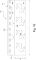
- FIGS 1A-E and 2A-B illustrate an edge trimming profile, designated globally by reference numeral 100, in accordance with a first embodiment of the invention.
- the edge trimming profile 100 is specifically designed to allow edge trimming of two adjacent sets of one or more tiles positioned on respective receiving surfaces forming an angle of substantially 90°, as in the case of a corner joining two perpendicular walls or a corner joining a step and a riser of a staircase.
- the edge trimming profile 100 can be arranged indifferently on a vertically or horizontally oriented receiving surface.
- the edge trimming profile 100 comprises a base leg member 110 to secure the edge trimming profile 100 to a receiving surface to be covered by a first set of one or more tiles, such as the receiving surface of a step of a staircase.
- the edge trimming profile 100 is secured to the relevant receiving surface, along with the associated tiles, by means of a suitable mortar, the base leg member 110 being provided with suitable through-openings 110A allowing mortar to penetrate and protrude through the base leg member 110 to favour securement of the overlying tile(s), as is typical in the art.
- the through-openings 110A may take any desired shape, including but not limited to the shape shown in Figures 1A-B and 1D-E .
- the base leg member 110 is preferably substantially planar, but variations could be contemplated.
- the base leg member 110 could for instance exhibit a slightly trapezoidal cross-section, with the thickness of the base leg member 110 reducing towards the distal end, as taught in British Patent No. GB 2 203 996 B .
- the upper surface 110a of the base leg member 110 is oriented towards one or more overlying tiles, while the lower surface 110b of the base leg member 110 is oriented towards the receiving surface that is to be covered by the relevant tiles.
- the edge trimming profile 100 further comprises an angled leg member 120 extending at an angle, designated ⁇ in Figure 1C , from a longitudinal end of the base leg member 110, as shown.
- the angled leg member 120 essentially consists of a rectilinear leg member ending with a widened protrusion at the distal end.
- the angled leg member 120 forms an angle ⁇ of substantially 135° with respect to the base leg member 110, and the angled leg member 120 includes a border portion 120A at the distal end that is destined to be exposed and form a visible trim TR along the peripheral edges of the two sets of tile(s) that are to be positioned on either side of the angled leg member 120.
- the angled leg member 120 further includes a first spacer structure 150 extending along a longitudinal direction and projecting away from a first surface 120a of the angled leg member 120.
- the spacer structure 150 is designed to come in abutment with a supporting surface Ts provided along the peripheral edge Tp of the set of one or more tiles T (only one tile T being shown in Figures 2A-B ) to maintain a spacing e between the trim TR and the peripheral edge Tp of the set of one or more tiles T.
- the spacer structure 150 does not consist of a continuous rib but is rather comprised of a plurality of spacer members 150 that are distributed in the longitudinal direction along the first surface 120a of the angled leg member 120 and that are spaced apart from one another. Thanks to this arrangement of the spacer members 150, grout applied to fill and seal gaps between the angled leg member 120 and the peripheral edge Tp of the set of one or more tiles T is allowed to pass through without being blocked by the spacer structure 150. As a result, the formation of a line of weakness is mitigated, as is the potential trapping of air pockets, which drastically improves robustness of the resulting joint.
- the angled leg member 120 further includes a second spacer structure 160 extending along the longitudinal direction and projecting away from a second surface 120b of the angled leg member 120, opposite the first surface 120a.
- This additional spacer structure 160 is similarly designed to come in abutment with a supporting surface provided along the peripheral edge of another, adjacent set of one or more tiles (such as tile(s) that would be provided on the receiving surface of a riser adjacent the aforementioned step) to maintain a spacing between the trim TR and the peripheral edge of the adjacent set of one or more tiles.
- the spacer structure 160 is likewise comprised of a plurality of spacer members 160 that are distributed in the longitudinal direction along the second surface 120b of the angled leg member 120 and that are spaced apart from one another.
- the border portion 120A forming the trim TR at the distal end of the angled leg member 120 is the only portion of the edge trimming profile 100 to ultimately be exposed and remain visible.
- the trim TR projects on both sides of the angled leg member 120 to form a head portion with a substantially triangular cross-section as shown in Figures 1A-C and 2A-B.
- the width w 1 of the trim TR as measured perpendicularly to a plane of the angled leg member 120 (see Figure 1C ), preferably does not exceed 5 mm. In the illustrated example, the width w 1 of the trim TR is of about 3.4 mm.
- the thickness d 1 of the trim TR, as measured within the plane of the angled leg member 120 preferably does not exceed 2 mm. In the illustrated example, the thickness d 1 of the trim TR is of about 1.6 mm.
- the angle, designated ⁇ is of substantially 90° in the illustrated example, although slightly wider or shallower angles could be contemplated.
- Each of the spacer members 150, 160 may exhibit a width w 2 of the order of 1 mm, in the illustrated example, and a length d 2 of the order to 1.5 mm.
- the spacer members 150, 160 are located at a distance h 2 with respect to the outer, extreme edge of the trim TR that is comprised between 4 mm and 6 mm.
- the overall height H of the edge trimming profile 100 is preferably comprised between approximately 4 mm and 22 mm. From a practical perspective, the edge trimming profile 100 may be produced in distinct standard heights H of e.g. 4.5 mm, 7 mm, 9 mm, 11 mm and 12.5 mm, or more.
- the overall length L of the edge trimming profile 100 is preferably comprised between approximately 100 mm and 3'000 mm. From a practical perspective, the edge trimming profile 100 may likewise be produced in distinct standard lengths L of e.g. 100 mm, 2'500 mm and 2'700 mm.
- the edge trimming profile 100 shown in Figures 1A-E and 2A-B corresponds to a standard overall height H of 12.5 mm and a standard overall length L of 100 mm.
- the width W of the base leg member 110 is, by way of illustration, of approximately 20 mm.
- the spacer members 150, 160 preferably have a length l 2 in the longitudinal direction of the order of 5 mm and are spaced apart from one another in the longitudinal direction by a spacing s 2 of the order of 5 mm. Considering an overall length L of 100 mm, one will therefore appreciate that a series of ten spacer members 150, 160 is provided on either side of the angled leg member 120 in the illustrated example.
- the peripheral edge Tp of each adjacent tile T that comes in abutment with the spacer members 150, resp. 160 is provided with a bevelled supporting surface Ts, namely a supporting surface Ts that is angled at 45° with respect to the upper side of the tile T and 135° with respect to the lower side of the tile T.
- the trim TR is aligned so that the outer surfaces thereof are coterminous and substantially flush with the upper, exposed surface of the adjacent tiles T, both horizontally and vertically.
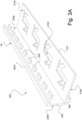
- FIGS 3A-E illustrate an edge trimming profile, designated globally by reference numeral 200, in accordance with a second embodiment of the invention.
- the edge trimming profile 200 is specifically designed to allow edge trimming of two adjacent sets of one or more tiles positioned on respective receiving surfaces forming an angle of substantially 90°, as in the case of a corner joining two perpendicular walls or a corner joining a step and riser of a staircase.
- the edge trimming profile 200 can be arranged indifferently on a vertically or horizontally oriented receiving surface.
- the edge trimming profile 200 comprises a base leg member 210 to secure the edge trimming profile 200 to a receiving surface to be covered by a first set of one or more tiles, such as the receiving surface of a step of a staircase.
- the edge trimming profile 200 is secured to the relevant receiving surface, along with the associated tiles, by means of a suitable mortar, the base leg member 210 being provided with suitable through-openings 210A allowing mortar to penetrate and protrude through the base leg member 210 to favour securement of the overlying tile(s), as is typical in the art.
- the through-openings 210A may once again take any desired shape, including but not limited to the shape shown in Figures 3A-B and 3D-E .
- the base leg member 210 is preferably substantially planar, but variations could similarly be contemplated.
- the upper surface 210a of the base leg member 210 is oriented towards one or more overlying tiles, while the lower surface 210b of the base leg member 210 is oriented towards the receiving surface that is to be covered by the relevant tiles.
- the edge trimming profile 200 further comprises an angled leg member 220 extending at an angle from a longitudinal end of the base leg member 210, as shown.
- the angled leg member 220 includes a border portion 220A that projects inwardly so as to form the trim TR into an angled corner comprising a connecting section connected to the base leg member 210, which connecting section forms an angle of substantially 90° with respect to the base leg member 210, and a terminal section extending away from the connecting section along a direction that is substantially parallel to a plane of the base leg member 210.
- the connecting section and terminal section of the trim TR are here joined to form the angled corner, as shown.
- the angled leg member 220 includes a spacer structure 250 that extends along a longitudinal direction and projects away from a first surface of the angled leg member 220, namely, the inner surface 220a of the connecting section.
- the spacer structure 250 is comprised of a plurality of spacer members 250 that are distributed in the longitudinal direction along the first surface 220a of the connecting section of the angled leg member 220 and that are spaced apart from one another.
- the spacer members 250 provided on the angled leg member 220 project from the connecting section of the trim TR along a direction that is substantially parallel to the plane of the base leg member 210 and protrude beyond the distal end of the terminal section of the trim TR.
- the base leg member 210 includes a supplemental spacer structure 260 extending along the longitudinal direction and projecting away from the lower surface 210b of the base leg member 210, opposite the angled leg member 220.
- This supplemental spacer structure 260 is similarly designed to come in abutment with a supporting surface provided along the peripheral edge of another, adjacent set of one or more tiles (such as tile(s) that would be provided on the receiving surface of a riser adjacent the aforementioned step) to maintain a spacing between the trim TR and the peripheral edge of the adjacent set of one or more tiles.
- the relevant spacing with respect to the trim TR is in effect maintained with the lower surface 210b of the base leg member 210.
- the supplemental spacer structure 260 is likewise comprised of a plurality of spacer members 260 that are distributed in the longitudinal direction along the lower surface 210b of the base leg member 210 and that are spaced apart from one another.
- grout applied to fill and seal gaps between the base leg member 210 and the peripheral edge of the adjacent set of one or more tiles is allowed to pass through without being blocked by the spacer structure 260.
- the border portion 220A forming the trim TR in effect consists of the outer surfaces of the angled leg member 220, including the outer surface of the connecting section (designated by reference sign 220b) and the outer surface of the terminal section, which outer surfaces are ultimately exposed and remain visible.
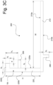
- the width w 1 of the trim TR as measured within the plane of the base leg member 210 (see Figure 3C ), preferably does not exceed 5 mm. In the illustrated example, the width w 1 of the trim TR is of about 3 mm.
- Each of the spacer members 250, 260 may exhibit a width that is comparable to that of the spacer members 150, 160 of the first embodiment, namely, a width of the order of 1 mm.
- a length d 2 of the spacer members 250 may for instance be of the order to 3 mm, which, along with the aforementioned width w 1 of the trim TR, defines the resulting spacing e between the trim TR and the adjacent, abutting tile(s).
- the spacer members 260 may be slightly shorter, with a length d 3 of the order of 2 mm or less.
- the spacer members 250 are located at a distance h 2 with respect to the outer, upper edge of the trim TR that is comprised between 4 mm and 6 mm, e.g. of 4.5 mm in the illustrated example.
- the overall height H of the edge trimming profile 200 is once again preferably comprised between approximately 4 mm and 22 mm. From a practical perspective, the edge trimming profile 200 may be produced in distinct standard heights H of e.g. 7 mm, 9 mm, 11 mm and 12.5 mm, or more.
- the overall length L of the edge trimming profile 200 is likewise preferably comprised between approximately 100 mm and 3'000 mm. From a practical perspective, the edge trimming profile 200 may similarly be produced in distinct standard lengths L of e.g. 100 mm, 2'500 mm and 2'700 mm.
- the edge trimming profile 200 shown in Figures 3A-E corresponds to a standard overall height H of 12.5 mm and a standard overall length L of 100 mm.
- the width W of the base leg member 210 is, by way of illustration, of approximately 20 to 25 mm.
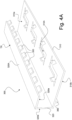
- FIGS 4A-E illustrate an edge trimming profile, designated globally by reference numeral 300, in accordance with a third embodiment of the invention.
- the edge trimming profile 300 is specifically designed to allow edge trimming of two adjacent sets of one or more tiles positioned on respective receiving surfaces forming an angle of substantially 90°, as in the case of a corner joining two perpendicular walls or a corner joining a step and riser of a staircase.
- the edge trimming profile 300 can be arranged indifferently on a vertically or horizontally oriented receiving surface.
- the edge trimming profile 300 comprises a base leg member 310 to secure the edge trimming profile 300 to a receiving surface to be covered by a first set of one or more tiles, such as the receiving surface of a step of staircase.
- the edge trimming profile 300 is secured to the relevant receiving surface, along with the associated tiles, by means of a suitable mortar, the base leg member 310 being provided with suitable through-openings 310A allowing mortar to penetrate and protrude through the base leg member 310 to favour securement of the overlying tile(s), as is typical in the art.
- the through-openings 310A may once again take any desired shape, including but not limited to the shape shown in Figures 4A-B and 4D-E.
- the base leg member 310 is preferably substantially planar, but variations could similarly be contemplated.
- the upper surface 310a of the base leg member 310 is oriented towards one or more overlying tiles, while the lower surface 310b of the base leg member 310 is oriented towards the receiving surface that is to be covered by the relevant tiles.
- the edge trimming profile 300 further comprises an angled leg member 320 extending at an angle from a longitudinal end of the base leg member 310, as shown.
- the angled leg member 320 includes a border portion 320A that projects inwardly so as to form the trim TR into an angled corner comprising a connecting section connected to the base leg member 310, which connecting section forms an angle of substantially 90° with respect to the base leg member 310, and a terminal section extending away from the connecting section along a direction that is substantially parallel to a plane of the base leg member 310.
- the connecting section and terminal section of the trim TR are here joined to form the angled corner, as shown.
- the angled leg member 320 includes a spacer structure 350 that extends along a longitudinal direction and projects away from a first surface of the angled leg member 320, namely, the inner, upper surface 320a of the terminal section of the trim TR.
- the spacer structure 350 is comprised of a plurality of spacer members 350 that are distributed in the longitudinal direction along the first surface 320a of the terminal section of the angled leg member 320 and that are spaced apart from one another.
- the spacer members 350 provided on the angled leg member 320 project at an angle, designated ⁇ in Figure 4C , from the terminal section of the trim TR toward the base leg member 310 and protrude beyond the distal end of the terminal section of the trim TR.
- the angle ⁇ is preferably chosen to be of approximately 135°, but other angles could be contemplated. Thanks to this arrangement of the spacer members 350, grout applied to fill and seal gaps between the angled leg member 320 and the peripheral edge of the set of one or more tiles is allowed to pass through without being blocked by the spacer structure 350, thereby achieving the same benefits as discussed above in connection with the first and second embodiments.
- the base leg member 310 includes a supplemental spacer structure 360 extending along the longitudinal direction and projecting away from the lower surface 310b of the base leg member 310, opposite the angled leg member 320.
- This supplemental spacer structure 360 fulfils the same purpose as the supplemental spacer structure 260 and is likewise comprised of a plurality of spacer members 360 that are distributed in the longitudinal direction along the lower surface 310b of the base leg member 310 and that are spaced apart from one another.
- grout applied to fill and seal gaps between the base leg member 310 and the peripheral edge of the adjacent set of one or more tiles is allowed to pass through without being blocked by the spacer structure 360.
- the border portion 320A forming the trim TR in effect consists of the outer surfaces of the angled leg member 320, including the outer surface of the connecting section (designated by reference sign 320b) and the outer surface of the terminal section, which outer surfaces are ultimately exposed and remain visible.
- the width w 1 of the trim TR as measured within the plane of the base leg member 310 (see Figure 4C ), preferably does not exceed 15 mm. In the illustrated example, the width w 1 of the trim TR is of about 10 mm.
- the thickness d 1 of the terminal section of the trim TR, as measured perpendicularly to the plane of the base leg member 310, preferably does not exceed 2 mm. In the illustrated example, the thickness d 1 of the terminal section of the trim TR is of about 1 mm.
- Each of the spacer members 350, 360 may exhibit a width that is comparable to that of the spacer members 150, 160 of the first embodiment or the spacer members 250, 260 of the second embodiment, namely, a width of the order of 1 mm.
- a height d 2 of the spacer members 350, as measured perpendicularly to the plane of the terminal section of trim TR, may for instance be of the order to 3 mm, which, along with the fact that the spacer members 350 are made to protrude beyond the distal end of the terminal section of the trim TR, defines the resulting spacing e between the trim TR and the adjacent, abutting tile(s).
- the spacer members 360 may exhibit a similar length d 3 of the order of 2 mm (or less) as the spacer members 260 of the second embodiment.
- the overall height H of the edge trimming profile 300 is once again preferably comprised between approximately 4 mm and 22 mm. From a practical perspective, the edge trimming profile 300 may be produced in distinct standard heights H of e.g. 7 mm, 9 mm, 11 mm and 12.5 mm, or more.
- the overall length L of the edge trimming profile 300 is likewise preferably comprised between approximately 100 mm and 3'000 mm. From a practical perspective, the edge trimming profile 300 may similarly be produced in distinct standard lengths L of e.g. 100 mm, 2'500 mm and 2'700 mm.
- the edge trimming profile 300 shown in Figures 4A-E corresponds to a standard overall height H of 12.5 mm and a standard overall length L of 100 mm.
- the width W of the base leg member 310 is, by way of illustration, of approximately 30 mm.
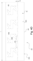
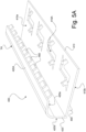
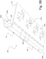
- FIGS 5A-E illustrate an edge trimming profile, designated globally by reference numeral 400, in accordance with a fourth embodiment of the invention.
- This edge trimming profile 400 is basically similar to the edge trimming profile 300 of the third embodiment, with the main difference residing in the shape of the border portion 420A of the angled leg member 420 and resulting trim TR that is shaped to form a rounded corner rather than an angled corner.
- the base leg member 410, angled leg member 420, spacer structure 450, and supplemental spacer structure 460 are substantially equivalent to the base leg member 310, angled leg member 320, spacer structure 350, and supplemental spacer structure 360 of the third embodiment, and the relevant considerations made in connection with the third embodiment of Figures 3A-E apply by analogy to the fourth embodiment shown in Figures 4A-E .
- the tip of the spacer members 150, 160, 250, 260, 350, 360, 450, 460 may take any desired shape ensuring adequate abutting of the adjacent tile(s).
- the tip may especially be square-shaped as shown e.g. in Figures 1A-C , 2B , rounded as shown e.g. in Figures 3A-C and 5A-C , or angled as shown e.g. in Figures 4A-C .
- the edge trimming profile of the invention may be made of a variety of materials, including a metal, such as stainless steel, anodized aluminium, or chrome-plated brass, a polymer, such as PVC, or a composite material.
- more than one base leg members could be contemplated to provide additional support for the edge trimming profile.
- two base leg members oriented at e.g. 90° from one another may for instance be contemplated in the context of the first embodiment discussed with reference to Figures 1A-E and 2A-B to provide support along the two receiving surfaces of the corner, as taught for instance in British Patent No. GB 2 203 996 B or French Utility Model No. FR 2 912 445 B3 .
- the supplemental spacer structure 260, 360, resp. 460 that is provided on the lower surface 210b, 310b, resp. 410b of the base leg member 210, 310, resp. 410 could simply be omitted.
- spacer members per se could exhibit any desired shape and do not necessarily need to be rectilinear as shown to provide for the desired spacing.
- the spacer members could for instance be angled or curved, while achieving the same benefits as discussed above.
Landscapes
- Engineering & Computer Science (AREA)
- Architecture (AREA)
- Civil Engineering (AREA)
- Structural Engineering (AREA)
- Finishing Walls (AREA)
Priority Applications (2)
| Application Number | Priority Date | Filing Date | Title |
|---|---|---|---|
| EP22181647.3A EP4299853A1 (fr) | 2022-06-28 | 2022-06-28 | Profilé de parement de bordure |
| PCT/IB2023/056660 WO2024003762A1 (fr) | 2022-06-28 | 2023-06-28 | Profilé de rognage de bord |
Applications Claiming Priority (1)
| Application Number | Priority Date | Filing Date | Title |
|---|---|---|---|
| EP22181647.3A EP4299853A1 (fr) | 2022-06-28 | 2022-06-28 | Profilé de parement de bordure |
Publications (1)
| Publication Number | Publication Date |
|---|---|
| EP4299853A1 true EP4299853A1 (fr) | 2024-01-03 |
Family
ID=82385363
Family Applications (1)
| Application Number | Title | Priority Date | Filing Date |
|---|---|---|---|
| EP22181647.3A Withdrawn EP4299853A1 (fr) | 2022-06-28 | 2022-06-28 | Profilé de parement de bordure |
Country Status (2)
| Country | Link |
|---|---|
| EP (1) | EP4299853A1 (fr) |
| WO (1) | WO2024003762A1 (fr) |
Citations (5)
| Publication number | Priority date | Publication date | Assignee | Title |
|---|---|---|---|---|
| GB2203996B (en) | 1987-04-28 | 1991-04-03 | Verto Limited | Edging strip |
| WO1998054423A1 (fr) | 1997-05-28 | 1998-12-03 | Schlüter-Systems Gmbh | Profile a coller sur un cote d'un subjectile pour l'obturation de plaques en ceramique posees ou analogues |
| US6357192B1 (en) * | 1998-12-14 | 2002-03-19 | Schluter-Systems Gmbh | Bridge device for providing a transition between two bordering floor segments of different levels |
| FR2912445B3 (fr) | 2007-02-14 | 2009-07-17 | Profili Italia S P A | Profile extrude pour des revetements en ceramique a appliquer en correspondance de l'arrete exterieure d'une paroi et methode de production y relative |
| CN105370016A (zh) * | 2015-11-10 | 2016-03-02 | 中国建筑第八工程局有限公司 | 收边条结构及其安装方法 |
-
2022
- 2022-06-28 EP EP22181647.3A patent/EP4299853A1/fr not_active Withdrawn
-
2023
- 2023-06-28 WO PCT/IB2023/056660 patent/WO2024003762A1/fr not_active Ceased
Patent Citations (6)
| Publication number | Priority date | Publication date | Assignee | Title |
|---|---|---|---|---|
| GB2203996B (en) | 1987-04-28 | 1991-04-03 | Verto Limited | Edging strip |
| WO1998054423A1 (fr) | 1997-05-28 | 1998-12-03 | Schlüter-Systems Gmbh | Profile a coller sur un cote d'un subjectile pour l'obturation de plaques en ceramique posees ou analogues |
| US6238773B1 (en) | 1997-05-28 | 2001-05-29 | Schlüter-Systems Kg | Profiled shape to be glued to a surface for finishing the edges of set ceramic tiles or similar items |
| US6357192B1 (en) * | 1998-12-14 | 2002-03-19 | Schluter-Systems Gmbh | Bridge device for providing a transition between two bordering floor segments of different levels |
| FR2912445B3 (fr) | 2007-02-14 | 2009-07-17 | Profili Italia S P A | Profile extrude pour des revetements en ceramique a appliquer en correspondance de l'arrete exterieure d'une paroi et methode de production y relative |
| CN105370016A (zh) * | 2015-11-10 | 2016-03-02 | 中国建筑第八工程局有限公司 | 收边条结构及其安装方法 |
Also Published As
| Publication number | Publication date |
|---|---|
| WO2024003762A1 (fr) | 2024-01-04 |
Similar Documents
| Publication | Publication Date | Title |
|---|---|---|
| US8074416B2 (en) | Structural members with gripping features and joining arrangements therefor | |
| CA2123713C (fr) | Procede de pose et dispositif de fixation de panneaux de toiture | |
| US7223043B1 (en) | Structural members and joining arrangements therefor | |
| CN101720373A (zh) | 用于建筑用途的组合式面板组件 | |
| US20120272604A1 (en) | Cladded structure and a fixing system for cladding | |
| CA2597186C (fr) | Element de fixation et structure de construction murale ainsi utilisee | |
| PL180242B1 (pl) | Blok sprzegany na zasadzie pióra i wpustu, do konstrukcji sciany i sciana skladajaca sie z wielu analogicznych bloków sprzeganych na zasadzie pióra i wpustu PL PL PL PL PL PL PL | |
| KR20080088532A (ko) | 바닥 및/또는 벽 타일용 조립 시스템 | |
| US7861470B2 (en) | Self centering shaft wall system | |
| RU2710047C2 (ru) | Вспомогательная крепежная опорная конструкция и способ ее установки | |
| US4383676A (en) | Railing system | |
| US20230358039A1 (en) | Wall panel module comprising dual gasket assembly | |
| US9803376B1 (en) | Deck system and methods of installing a deck | |
| KR20250004061A (ko) | 이중 가스켓 조립체를 포함하는 벽 패널 모듈을 제조하기 위한 프로세스 | |
| KR20250004365A (ko) | 패널 간 조인트를 밀봉하기 위한 이중 가스켓 조립체 | |
| KR20250004370A (ko) | 이중 가스켓 조립체에 의해 밀봉된 접경 조인트를 갖는 패널형 벽을 제조하기 위한 프로세스 | |
| KR20250004060A (ko) | 이중 가스켓 조립체를 포함하는 패널형 벽 시스템 | |
| KR20250004071A (ko) | 이중 가스켓 조립체를 위한 물 배수 덕트 | |
| WO2024003762A1 (fr) | Profilé de rognage de bord | |
| US3244406A (en) | Joint for a structural assembly | |
| MX2010011903A (es) | Escuadra de soporte para anclar losetas de revestimiento exterior sobrepuestas, a una estructura de pared. | |
| WO2010028476A1 (fr) | Contremarche de stade en métal extrudé | |
| EP1867801A1 (fr) | Panneau de revêtement en tôle | |
| KR102642521B1 (ko) | 건축물의 외장 패널 어셈블리 | |
| KR20240120194A (ko) | 시공이 쉬운 두겁대 |
Legal Events
| Date | Code | Title | Description |
|---|---|---|---|
| PUAI | Public reference made under article 153(3) epc to a published international application that has entered the european phase |
Free format text: ORIGINAL CODE: 0009012 |
|
| STAA | Information on the status of an ep patent application or granted ep patent |
Free format text: STATUS: THE APPLICATION HAS BEEN PUBLISHED |
|
| AK | Designated contracting states |
Kind code of ref document: A1 Designated state(s): AL AT BE BG CH CY CZ DE DK EE ES FI FR GB GR HR HU IE IS IT LI LT LU LV MC MK MT NL NO PL PT RO RS SE SI SK SM TR |
|
| STAA | Information on the status of an ep patent application or granted ep patent |
Free format text: STATUS: THE APPLICATION IS DEEMED TO BE WITHDRAWN |
|
| 18D | Application deemed to be withdrawn |
Effective date: 20240704 |