EP4299904B1 - Procédé de régulation de pompes à fluide à vitesse variable - Google Patents
Procédé de régulation de pompes à fluide à vitesse variable Download PDFInfo
- Publication number
- EP4299904B1 EP4299904B1 EP23180502.9A EP23180502A EP4299904B1 EP 4299904 B1 EP4299904 B1 EP 4299904B1 EP 23180502 A EP23180502 A EP 23180502A EP 4299904 B1 EP4299904 B1 EP 4299904B1
- Authority
- EP
- European Patent Office
- Prior art keywords
- pressure
- target
- speed
- value
- control loop
- Prior art date
- Legal status (The legal status is an assumption and is not a legal conclusion. Google has not performed a legal analysis and makes no representation as to the accuracy of the status listed.)
- Active
Links
Images

Classifications
-
- F—MECHANICAL ENGINEERING; LIGHTING; HEATING; WEAPONS; BLASTING
- F04—POSITIVE - DISPLACEMENT MACHINES FOR LIQUIDS; PUMPS FOR LIQUIDS OR ELASTIC FLUIDS
- F04B—POSITIVE-DISPLACEMENT MACHINES FOR LIQUIDS; PUMPS
- F04B17/00—Pumps characterised by combination with, or adaptation to, specific driving engines or motors
- F04B17/03—Pumps characterised by combination with, or adaptation to, specific driving engines or motors driven by electric motors
-
- F—MECHANICAL ENGINEERING; LIGHTING; HEATING; WEAPONS; BLASTING
- F04—POSITIVE - DISPLACEMENT MACHINES FOR LIQUIDS; PUMPS FOR LIQUIDS OR ELASTIC FLUIDS
- F04B—POSITIVE-DISPLACEMENT MACHINES FOR LIQUIDS; PUMPS
- F04B49/00—Control, e.g. of pump delivery, or pump pressure of, or safety measures for, machines, pumps, or pumping installations, not otherwise provided for, or of interest apart from, groups F04B1/00 - F04B47/00
- F04B49/06—Control using electricity
-
- F—MECHANICAL ENGINEERING; LIGHTING; HEATING; WEAPONS; BLASTING
- F04—POSITIVE - DISPLACEMENT MACHINES FOR LIQUIDS; PUMPS FOR LIQUIDS OR ELASTIC FLUIDS
- F04B—POSITIVE-DISPLACEMENT MACHINES FOR LIQUIDS; PUMPS
- F04B49/00—Control, e.g. of pump delivery, or pump pressure of, or safety measures for, machines, pumps, or pumping installations, not otherwise provided for, or of interest apart from, groups F04B1/00 - F04B47/00
- F04B49/06—Control using electricity
- F04B49/065—Control using electricity and making use of computers
-
- F—MECHANICAL ENGINEERING; LIGHTING; HEATING; WEAPONS; BLASTING
- F04—POSITIVE - DISPLACEMENT MACHINES FOR LIQUIDS; PUMPS FOR LIQUIDS OR ELASTIC FLUIDS
- F04B—POSITIVE-DISPLACEMENT MACHINES FOR LIQUIDS; PUMPS
- F04B49/00—Control, e.g. of pump delivery, or pump pressure of, or safety measures for, machines, pumps, or pumping installations, not otherwise provided for, or of interest apart from, groups F04B1/00 - F04B47/00
- F04B49/20—Control, e.g. of pump delivery, or pump pressure of, or safety measures for, machines, pumps, or pumping installations, not otherwise provided for, or of interest apart from, groups F04B1/00 - F04B47/00 by changing the driving speed
-
- F—MECHANICAL ENGINEERING; LIGHTING; HEATING; WEAPONS; BLASTING
- F04—POSITIVE - DISPLACEMENT MACHINES FOR LIQUIDS; PUMPS FOR LIQUIDS OR ELASTIC FLUIDS
- F04B—POSITIVE-DISPLACEMENT MACHINES FOR LIQUIDS; PUMPS
- F04B2201/00—Pump parameters
- F04B2201/12—Parameters of driving or driven means
- F04B2201/1201—Rotational speed of the axis
-
- F—MECHANICAL ENGINEERING; LIGHTING; HEATING; WEAPONS; BLASTING
- F04—POSITIVE - DISPLACEMENT MACHINES FOR LIQUIDS; PUMPS FOR LIQUIDS OR ELASTIC FLUIDS
- F04B—POSITIVE-DISPLACEMENT MACHINES FOR LIQUIDS; PUMPS
- F04B2201/00—Pump parameters
- F04B2201/12—Parameters of driving or driven means
- F04B2201/1202—Torque on the axis
-
- F—MECHANICAL ENGINEERING; LIGHTING; HEATING; WEAPONS; BLASTING
- F04—POSITIVE - DISPLACEMENT MACHINES FOR LIQUIDS; PUMPS FOR LIQUIDS OR ELASTIC FLUIDS
- F04B—POSITIVE-DISPLACEMENT MACHINES FOR LIQUIDS; PUMPS
- F04B2203/00—Motor parameters
- F04B2203/02—Motor parameters of rotating electric motors
- F04B2203/0201—Current
-
- F—MECHANICAL ENGINEERING; LIGHTING; HEATING; WEAPONS; BLASTING
- F04—POSITIVE - DISPLACEMENT MACHINES FOR LIQUIDS; PUMPS FOR LIQUIDS OR ELASTIC FLUIDS
- F04B—POSITIVE-DISPLACEMENT MACHINES FOR LIQUIDS; PUMPS
- F04B2203/00—Motor parameters
- F04B2203/02—Motor parameters of rotating electric motors
- F04B2203/0207—Torque
-
- F—MECHANICAL ENGINEERING; LIGHTING; HEATING; WEAPONS; BLASTING
- F04—POSITIVE - DISPLACEMENT MACHINES FOR LIQUIDS; PUMPS FOR LIQUIDS OR ELASTIC FLUIDS
- F04B—POSITIVE-DISPLACEMENT MACHINES FOR LIQUIDS; PUMPS
- F04B2205/00—Fluid parameters
- F04B2205/05—Pressure after the pump outlet
Definitions
- the present invention relates to a method for controlling variable speed fluid pumps, as well as a computer program and a computing unit for carrying out the method.
- fluid pumps are often used with a pumping mechanism with a fixed delivery volume, which is driven by a drive with variable speed (so-called variable speed constant pump).
- variable speed variable speed constant pump
- the volume flow and/or the delivery pressure are usually regulated by adjusting the speed accordingly.
- Such pumps are used, for example, for hydraulic units, pump drives or servo-hydraulic actuators, for example in machine tools or in plastics processing, such as in injection molding machines, blow molding machines, presses, etc., where high delivery pressures are required.
- variable speed pumps can be implemented, for example, by a cascaded controller structure in which a target pressure is specified and includes a pressure control circuit, a speed control circuit and a current control circuit for the drive motor.
- a target pressure is specified and includes a pressure control circuit, a speed control circuit and a current control circuit for the drive motor.
- the speed control circuit is disturbed by the load torque M L , which is set depending on the current pressure via the pump displacement volume.
- the pressure control circuit is also disturbed by the leakage volume flow of the pump.
- WO 2018/0207157 A2 shows a method for controlling pressure and flow of hydraulic fluid through a hydraulic control unit, which includes receiving a pressure command from an electronic control unit.
- the received pressure command is processed to generate a pressure-based torque command and a shaft angle-based torque command or a volume-based torque command.
- the generated pressure-based torque command and the generated shaft angle-based torque command or the volume-based torque command are processed to further generate a duty cycle for a field-oriented controlled motor.
- the DE 10 2019 220 322 A1 relates to a method for operating a variable speed variable displacement pump, in which a conveyor mechanism adjustable in a displacement volume per working cycle is driven by means of a variable speed drive, wherein within the framework of a control at least one variable is controlled to a setpoint by specifying a speed setpoint for a speed of the drive and a setpoint for a parameter determining the displacement volume per working cycle, wherein the speed setpoint is adapted by means of a feedforward control in the event of a change in the setpoint for the parameter determining the displacement volume per working cycle.
- a method is proposed in which a target pressure value is first entered into a cascaded controller structure, wherein the controller structure comprises a pressure control loop and wherein the control system of the pressure control loop comprises a speed control loop into which a target speed is entered as a control variable of a pressure controller of the pressure control loop.
- the control system of the speed control loop also comprises a drive control loop into which a target drive torque is entered as a control variable of a speed controller of the speed control loop.
- a pre-control value for the drive torque is as a result of a time differential equation of the target pressure, and this pilot value is added to the target drive torque, which is input into the control system of the speed control loop.
- the temporal differential equation of the target pressure comprises an inverse system model of the controlled system of the cascaded controller structure.
- This inverse system model can, for example, be formed depending on a pressure dynamics in a load volume in which the pressure is controlled and a torque dynamics of the drive.
- J eq is an equivalent moment of inertia
- C h is a hydraulic capacity
- V g is a displacement volume of the pump
- p L d is a target load pressure
- C l is a pressure-dependent leakage coefficient
- d M is a speed-related friction torque of the pump.
- n cmd ff C h V g p ⁇ L d + C l V g ⁇ p L d
- C h is the hydraulic capacity
- V g is the displacement volume of the pump
- p L d is the target load pressure
- C l is the pressure-dependent leakage coefficient
- This pre-control value can then be added to the target speed, which is output by the pressure controller as a control variable. This can prevent the speed control loop from working against the torque pre-control.
- the target pressure value can be entered into a target value filter which is configured to output a target trajectory for the target pressure value and the derivatives of the target pressure value, and this target trajectory can then be entered into the differential equation for forming the pilot control value.
- Such a setpoint filter may, for example, comprise a second-order state variable binomial filter.
- the flatness-based feedforward control proposed here dynamically compensates for load torques and disturbance volume flows. This improves the control behavior and the stability reserve of the system.
- the drive controller can be designed for interference immunity, since the follow-up behavior is significantly improved by the feedforward control. This relieves the load on the speed and pressure controllers. At the same time, the feedforward control is insensitive to sensor noise.
- a computing unit according to the invention e.g. a control unit of a hydraulic system, is set up, in particular in terms of programming, to carry out a method according to the invention.
- Suitable data carriers for providing the computer program are in particular magnetic, optical and electrical storage devices, such as hard disks, flash memories, EEPROMs, DVDs, etc. It is also possible to download a program via computer networks (Internet, intranet, etc.).
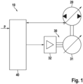
- FIG. 1 shows schematically components of a variable speed fluid pump for which the methods described here can be applied.
- the pump 10 has a conveyor 20 which can convey in two directions, a variable speed drive 30 and a computing unit 40 for operating the pump.
- the conveyor 20 can be designed, for example, as a constant pump that achieves a certain delivery volume per stroke or per revolution.
- the drive 30 is designed here as a standard motor that has an asynchronous motor 31 and a frequency converter 32. Alternatively, synchronous servo motors or other drive units can also be used.
- the speed n of the asynchronous motor 31 is variable, with the speed being set, for example, by the current applied to the drive motor 31.
- the computing unit 40 can be used to control the pump 10, to which at least one target delivery pressure and optionally a target volume flow are supplied.
- the computing unit 40 can comprise a drive controller implemented in hardware or software, which determines the required control variables and transmits them to the motor 30.
- the actual pressure can be determined using a sensor.
- the computing unit 40 can further determine, e.g. by monitoring the electrical current and the speed, which drive torque is currently being delivered by the drive, and can then, for example, transmit a target speed to the drive unit 30 as a control signal.
- the drive unit 30 itself to comprise certain control or regulation elements, and thus for the computing unit 40 to, for example, only specify a target torque for controlling the drive and thus the pump and transmit this to the drive 30 as a control signal.
- Figure 2 shows a controller structure for controlling a variable speed fluid pump according to a possible embodiment.
- a cascaded controller structure is provided which nests a pressure control loop, a speed control loop and a drive control loop such as a current control loop.
- the current control loop 230 for the pump drive is shown here only in a simplified and exemplary manner and can be implemented in any way, e.g. as a PI controller; with a different drive variant, a different control loop can also be used at this point which controls a drive torque of a pump drive.
- the current control loop 230 receives a target drive torque M R cmd as a reference variable and feeds back the actual value 232 of the drive torque M act . A controlled drive torque M M is thus obtained.
- the target drive torque M R cmd is in turn the manipulated variable of a speed control loop.
- the speed control loop receives a target speed n cmd of the pump as a reference variable for a speed controller 220 and feeds back an actual speed n act 222, whereby the current control loop 230 together with the moment of inertia element 224, which outputs the controlled speed n from the drive torque M M with the moment of inertia of the pump and motor, forms the controlled system of the speed control loop.
- the target speed n cmd forms the manipulated variable of a pressure control loop, the pressure controller 210 of which receives a target load pressure p L d as a reference variable and feeds back 212 an actual value p L of the load pressure.
- the control system of the pressure control loop thus comprises the speed control loop 220, 222, 224, the current control loop 230, 232 and further control elements.
- the further control elements of the system comprise a proportional element 214 in order to convert the controlled speed n obtained from the speed control loop into a volume flow Q p by taking into account the predetermined displacement volume V g of the pump per revolution.
- the controlled load pressure p L is then obtained by means of a PI element 216 from the volume flow Q p by taking into account the equivalent compression module E' oil and the load volume V L in which the pressure is regulated.
- the actual pressure p act is in turn fed back via the pressure control circuit 212 to the input of the pressure regulator 210.
- the speed control loop is disturbed by a load torque M L , which can be represented as a proportional element 240 from the existing load pressure p L and the displacement volume V g of the pump.
- the resulting load torque M L counteracts the drive torque M M .
- the pressure control loop is disturbed by the leakage volume flow Q L of the pump, which results from the load pressure p L and the leakage coefficient C l and can be modeled as a proportional element 242.
- the leakage volume flow Q L counteracts the volume flow Q p of the pump.
- a pilot control 250 can now be provided according to the invention, which corrects the commanded drive torque M R cmd for the pump drive, which is output by the speed controller 220 as a manipulated variable and enters the current control loop 230 as a reference variable, by means of a pilot control value M ff cmd .
- the actual value that is thus entered into the current control loop or the controlled system of the speed control loop is therefore the sum of the drive torque M R cmd and the pilot control value M ff cmd .
- the pre-control value can be formed in particular via an inverse system model of the controlled system.
- This system model can be configured according to the Figure 2 shown controller structure can be derived as follows:
- C h V L / E' oil is the hydraulic capacity with the equivalent compression modulus E ' oil and the load volume V L
- V g is the displacement of the pump
- ⁇ M is the torque of the drive
- C l is the pressure dependent leakage coefficient.
- the superimposed speed control loop can optionally also be supplied with the pilot control signal from which the torque pilot control is derived. This can prevent the speed control loop from working against the torque pilot control.
- This feedforward value can then be added to the input of the speed control loop.
- the time derivatives of the target pressure p L p ⁇ L p ⁇ L by a setpoint filter 260 For example, a second-order state variable binomial filter can be used for this purpose.
- the setpoint pressure values can also be determined differently.
- p cmd is the commanded setpoint pressure value.
- the target trajectory obtained from equation (7) can now be inserted into the pre-control law, equation (5), and the pre-control torque M ff cmd calculated with it can be added to the input of the current control loop 230.
- the target trajectories can also be inserted into the pre-control law (6) for the speed.
- the pre-control value is then added to the output value of the speed controller 220 or the input value of the current control loop 230 as in the previous embodiment.
- the control behavior of the control system is improved, since the actuator (i.e. the drive motor of the pump) reacts immediately in a highly dynamic manner, even if no large control deviation occurs.
- the actuator i.e. the drive motor of the pump
- the follow-up behavior of the drive control i.e. the current control loop
- the feedforward control is also significantly improved by the feedforward control. This reduces the load on the speed and pressure controllers.
- the feedforward control is insensitive to sensor noise.
- a control system as described here can be used for all variable speed pumps, especially for pumps for controlling hydraulic units or hydraulic actuators.
- the described method with pilot control can also be used for the force control of servo-hydraulic actuators; in this case, a pressure is also controlled via a motor-pump unit, which can then be converted into a force value via the cylinder surfaces.
Landscapes
- Engineering & Computer Science (AREA)
- Mechanical Engineering (AREA)
- General Engineering & Computer Science (AREA)
- Computer Hardware Design (AREA)
- Control Of Positive-Displacement Pumps (AREA)
Claims (9)
- Procédé permettant de réguler une pompe avec un entraînement à vitesse de rotation variable, comprenant les étapes consistant à : entrer une valeur de pression de consigne (pcmd ) dans une structure de régulateur en cascade, la structure de régulateur comprenant un circuit de régulation de pression (210, 212, 214, 216),dans lequel le système réglé du circuit de régulation de pression comprend un circuit de régulation de vitesse de rotation (220, 222, 224) dans lequel une vitesse de rotation de consigne (ncmd) est entrée en tant que grandeur de réglage d'un régulateur de pression (210) du circuit de régulation de pression ;dans lequel le système réglé du circuit de régulation de vitesse de rotation comprend un circuit de régulation d'entraînement (230, 232) dans lequel un couple d'entraînement de consigne (MR cmd) est entré en tant que grandeur de réglage d'un régulateur de vitesse de rotation (220) du circuit de régulation de vitesse de rotation ;former (250) une valeur pilote (Mff cmd ) pour le couple d'entraînement en tant que résultat d'une équation différentielle temporelle de la pression de consigne ; etadditionner la valeur pilote au couple d'entraînement de consigne qui est entré dans le système réglé du circuit de régulation de vitesse de rotation,dans lequel l'équation différentielle temporelle de la pression de consigne comprend un modèle de système inverse du système réglé de la structure de régulateur en cascade.
- Procédé selon la revendication 1, dans lequel le modèle de système inverse est formé en fonction d'une dynamique de pression dans un volume de charge dans lequel la pression est régulée, et d'une dynamique de couple de rotation de l'entraînement.
- Procédé selon l'une quelconque des revendications précédentes, la valeur pilote pour le couple d'entraînement étant déterminée par :

- Procédé selon l'une quelconque des revendications précédentes, comprenant en outre les étapes consistant à : former une valeur pilote (nff cmd) pour la vitesse de rotation, la valeur pilote pour la vitesse de rotation étant déterminée par :
 où Ch est la capacité hydraulique, Vg est le volume d'absorption de la pompe, Cl est le coefficient de fuite dépendant de la pression et pL d est la pression de charge de consigne,et additionner la valeur pilote à la vitesse de rotation de consigne qui est sortie par le régulateur de pression (210) en tant que grandeur de réglage.
 - Procédé selon l'une quelconque des revendications précédentes, comprenant en outre les étapes consistant à :entrer la valeur de pression de consigne dans un filtre de valeur de consigne (260) qui est conçu pour sortir une trajectoire de consigne pour la valeur de pression de consigne et les dérivations de la valeur de pression de consigne, etentrer la trajectoire de consigne dans l'équation différentielle pour former la valeur pilote.
- Procédé selon la revendication 5, dans lequel le filtre de valeur de consigne comprend un filtre binomial de variables d'état de deuxième ordre.
- Unité de calcul (40), comprenant un processeur qui est configuré de telle sorte qu'il exécute le procédé selon l'une quelconque des revendications précédentes.
- Programme informatique comprenant des instructions qui, lors de l'exécution du programme par un ordinateur, amènent celui-ci à exécuter le procédé selon les revendications 1 à 6.
- Support de données lisible par ordinateur, sur lequel est stocké le programme informatique selon la revendication 8.
Applications Claiming Priority (1)
| Application Number | Priority Date | Filing Date | Title |
|---|---|---|---|
| DE102022206540.9A DE102022206540B3 (de) | 2022-06-28 | 2022-06-28 | Verfahren zur Regelung von drehzahlvariablen Fluidpumpen |
Publications (2)
| Publication Number | Publication Date |
|---|---|
| EP4299904A1 EP4299904A1 (fr) | 2024-01-03 |
| EP4299904B1 true EP4299904B1 (fr) | 2025-02-26 |
Family
ID=86942320
Family Applications (1)
| Application Number | Title | Priority Date | Filing Date |
|---|---|---|---|
| EP23180502.9A Active EP4299904B1 (fr) | 2022-06-28 | 2023-06-21 | Procédé de régulation de pompes à fluide à vitesse variable |
Country Status (3)
| Country | Link |
|---|---|
| EP (1) | EP4299904B1 (fr) |
| CN (1) | CN117307469A (fr) |
| DE (1) | DE102022206540B3 (fr) |
Families Citing this family (1)
| Publication number | Priority date | Publication date | Assignee | Title |
|---|---|---|---|---|
| DE102023130277B4 (de) | 2023-11-02 | 2026-04-09 | Dr. Ing. H.C. F. Porsche Aktiengesellschaft | Verfahren zum Betreiben eines drehzahlgeregelten Elektromotors einer Motorpumpeneinheit für ein aktives Fahrwerk |
Family Cites Families (9)
| Publication number | Priority date | Publication date | Assignee | Title |
|---|---|---|---|---|
| DE102005039758A1 (de) | 2005-08-23 | 2007-03-01 | Robert Bosch Gmbh | Verfahren und Vorrichtung zum Betreiben einer Brennkraftmaschine |
| US8414270B2 (en) * | 2010-11-12 | 2013-04-09 | GM Global Technology Operations LLC | Speed control of an electrically-actuated fluid pump |
| DE102012009136A1 (de) | 2012-05-05 | 2013-11-07 | Robert Bosch Gmbh | Verfahren zum Betreiben einer Fluidpumpe |
| EP4450845A3 (fr) * | 2013-03-15 | 2025-01-01 | ClearMotion, Inc. | Améliorations de suspension active de véhicule |
| DE102014224337B4 (de) | 2014-11-28 | 2023-05-04 | Robert Bosch Gmbh | Verfahren zur Steuerung eines hydrostatischen Antriebs |
| DE102015221684A1 (de) | 2015-11-05 | 2017-05-11 | Robert Bosch Gmbh | Verfahren zum durcksensorlosen Stellen des Drucks eines mittels einer drehzahlgeregelten Pumpe geförderten Fluids |
| WO2018207157A2 (fr) * | 2017-05-11 | 2018-11-15 | Eaton Intelligent Power Limited | Commande de pression dans un système hydraulique à tête morte utilisant une commande de mouvement de pompe |
| DE102017117595A1 (de) | 2017-08-03 | 2019-02-07 | Voith Patent Gmbh | Verfahren zur regelung des ausgangsdrucks eines hydraulikantriebsystems, verwendung des verfahrens und hydraulikantriebsystem |
| DE102019220322A1 (de) | 2019-12-20 | 2021-06-24 | Robert Bosch Gesellschaft mit beschränkter Haftung | Verfahren zum Betreiben einer drehzahlvariablen Verstellpumpe |
-
2022
- 2022-06-28 DE DE102022206540.9A patent/DE102022206540B3/de active Active
-
2023
- 2023-06-21 EP EP23180502.9A patent/EP4299904B1/fr active Active
- 2023-06-27 CN CN202310769484.5A patent/CN117307469A/zh active Pending
Also Published As
| Publication number | Publication date |
|---|---|
| EP4299904A1 (fr) | 2024-01-03 |
| DE102022206540B3 (de) | 2023-10-12 |
| CN117307469A (zh) | 2023-12-29 |
Similar Documents
| Publication | Publication Date | Title |
|---|---|---|
| AT515590B1 (de) | Dynamischer Sollwertausgleich bei drehzahlvariablen Verstellpumpen | |
| DE112011101683B4 (de) | Motorsteuervorrichtung | |
| EP2597310B1 (fr) | Procédé de fonctionnement d'une pompe à débit et vitesse de rotation variables | |
| EP3098448B1 (fr) | Procédé et circuit de régulation d'un entraînement électrique d'un compresseur pneumatique électrique | |
| DE102014226634B3 (de) | Verfahren zum Betreiben eines hydraulischen Antriebs, Recheneinheit, Computerprogramm und maschinenlesbares Speichermedium | |
| EP2138380A1 (fr) | Dispositif et procédé destinés au fonctionnement d'un système de direction assistée ayant une tolérance d'intervention du conducteur | |
| DE102012009136A1 (de) | Verfahren zum Betreiben einer Fluidpumpe | |
| EP2192309B1 (fr) | Procédé et circuit de réglage destinés au réglage d'une alimentation en fluide sous pression pour un actionneur hydraulique | |
| DE102017213650A1 (de) | Verfahren zum Regeln eines hydraulischen Systems, Regeleinheit für ein hydraulisches System und hydraulisches System | |
| DE102009018071B4 (de) | Verfahren und Regelvorrichtung zur Regelung einer Druckmittelzufuhr für einen hydraulischen Aktor | |
| EP3988801A1 (fr) | Procédé de fonctionnement d'un entraînement hydraulique | |
| DE102022206540B3 (de) | Verfahren zur Regelung von drehzahlvariablen Fluidpumpen | |
| EP4299919A1 (fr) | Procédé de régulation de composants hydrauliques | |
| EP2513490B1 (fr) | Méthode d'exploitation d'une machine hydraulique | |
| DE102015221684A1 (de) | Verfahren zum durcksensorlosen Stellen des Drucks eines mittels einer drehzahlgeregelten Pumpe geförderten Fluids | |
| EP4081871B1 (fr) | Procédé de commande d'un système partiellement électronique | |
| DE102016214708A1 (de) | Stetigventileinheit, hydraulische Achse und Verfahren zum Betreiben einer hydraulischen Achse | |
| EP2199879A1 (fr) | Dispositif et procédé de minimisation d'une erreur de suivi dynamique | |
| DE102018210441B4 (de) | Servomotorsteuerung | |
| DE102018121926A1 (de) | Motorsteuervorrichtung und Motorsteuerverfahren | |
| DE102022208574A1 (de) | Verfahren zum Betreiben eines hydraulischen Antriebs einer Maschine und hydraulischer Antrieb | |
| AT522651B1 (de) | Verfahren und Regelschaltung zur Regelung einer Druckmittelzufuhr für einen hydraulischen Aktor | |
| DE102011008923B4 (de) | Verfahren zum Steuern und/oder Regeln einer Hydraulische Antriebseinheit, Hydraulische Antriebseinheit sowie Spritzgießmaschine | |
| DE102022203051B3 (de) | Verfahren zum Betreiben einer drehzahlvariablen Pumpe | |
| WO2012007114A2 (fr) | Groupe hydraulique |
Legal Events
| Date | Code | Title | Description |
|---|---|---|---|
| PUAI | Public reference made under article 153(3) epc to a published international application that has entered the european phase |
Free format text: ORIGINAL CODE: 0009012 |
|
| STAA | Information on the status of an ep patent application or granted ep patent |
Free format text: STATUS: THE APPLICATION HAS BEEN PUBLISHED |
|
| AK | Designated contracting states |
Kind code of ref document: A1 Designated state(s): AL AT BE BG CH CY CZ DE DK EE ES FI FR GB GR HR HU IE IS IT LI LT LU LV MC ME MK MT NL NO PL PT RO RS SE SI SK SM TR |
|
| STAA | Information on the status of an ep patent application or granted ep patent |
Free format text: STATUS: REQUEST FOR EXAMINATION WAS MADE |
|
| 17P | Request for examination filed |
Effective date: 20240703 |
|
| RBV | Designated contracting states (corrected) |
Designated state(s): AL AT BE BG CH CY CZ DE DK EE ES FI FR GB GR HR HU IE IS IT LI LT LU LV MC ME MK MT NL NO PL PT RO RS SE SI SK SM TR |
|
| GRAP | Despatch of communication of intention to grant a patent |
Free format text: ORIGINAL CODE: EPIDOSNIGR1 |
|
| STAA | Information on the status of an ep patent application or granted ep patent |
Free format text: STATUS: GRANT OF PATENT IS INTENDED |
|
| INTG | Intention to grant announced |
Effective date: 20241202 |
|
| RIC1 | Information provided on ipc code assigned before grant |
Ipc: F04B 49/20 20060101ALI20241122BHEP Ipc: F04B 49/06 20060101ALI20241122BHEP Ipc: F04B 17/03 20060101AFI20241122BHEP |
|
| GRAS | Grant fee paid |
Free format text: ORIGINAL CODE: EPIDOSNIGR3 |
|
| GRAA | (expected) grant |
Free format text: ORIGINAL CODE: 0009210 |
|
| STAA | Information on the status of an ep patent application or granted ep patent |
Free format text: STATUS: THE PATENT HAS BEEN GRANTED |
|
| AK | Designated contracting states |
Kind code of ref document: B1 Designated state(s): AL AT BE BG CH CY CZ DE DK EE ES FI FR GB GR HR HU IE IS IT LI LT LU LV MC ME MK MT NL NO PL PT RO RS SE SI SK SM TR |
|
| REG | Reference to a national code |
Ref country code: GB Ref legal event code: FG4D Free format text: NOT ENGLISH |
|
| REG | Reference to a national code |
Ref country code: CH Ref legal event code: EP |
|
| REG | Reference to a national code |
Ref country code: DE Ref legal event code: R096 Ref document number: 502023000605 Country of ref document: DE |
|
| REG | Reference to a national code |
Ref country code: IE Ref legal event code: FG4D Free format text: LANGUAGE OF EP DOCUMENT: GERMAN |
|
| REG | Reference to a national code |
Ref country code: SE Ref legal event code: TRGR |
|
| REG | Reference to a national code |
Ref country code: NL Ref legal event code: MP Effective date: 20250226 |
|
| PG25 | Lapsed in a contracting state [announced via postgrant information from national office to epo] |
Ref country code: RS Free format text: LAPSE BECAUSE OF FAILURE TO SUBMIT A TRANSLATION OF THE DESCRIPTION OR TO PAY THE FEE WITHIN THE PRESCRIBED TIME-LIMIT Effective date: 20250526 |
|
| PG25 | Lapsed in a contracting state [announced via postgrant information from national office to epo] |
Ref country code: FI Free format text: LAPSE BECAUSE OF FAILURE TO SUBMIT A TRANSLATION OF THE DESCRIPTION OR TO PAY THE FEE WITHIN THE PRESCRIBED TIME-LIMIT Effective date: 20250226 |
|
| PG25 | Lapsed in a contracting state [announced via postgrant information from national office to epo] |
Ref country code: PL Free format text: LAPSE BECAUSE OF FAILURE TO SUBMIT A TRANSLATION OF THE DESCRIPTION OR TO PAY THE FEE WITHIN THE PRESCRIBED TIME-LIMIT Effective date: 20250226 |
|
| PG25 | Lapsed in a contracting state [announced via postgrant information from national office to epo] |
Ref country code: ES Free format text: LAPSE BECAUSE OF FAILURE TO SUBMIT A TRANSLATION OF THE DESCRIPTION OR TO PAY THE FEE WITHIN THE PRESCRIBED TIME-LIMIT Effective date: 20250226 |
|
| REG | Reference to a national code |
Ref country code: LT Ref legal event code: MG9D |
|
| PG25 | Lapsed in a contracting state [announced via postgrant information from national office to epo] |
Ref country code: IS Free format text: LAPSE BECAUSE OF FAILURE TO SUBMIT A TRANSLATION OF THE DESCRIPTION OR TO PAY THE FEE WITHIN THE PRESCRIBED TIME-LIMIT Effective date: 20250626 Ref country code: NO Free format text: LAPSE BECAUSE OF FAILURE TO SUBMIT A TRANSLATION OF THE DESCRIPTION OR TO PAY THE FEE WITHIN THE PRESCRIBED TIME-LIMIT Effective date: 20250526 |
|
| PG25 | Lapsed in a contracting state [announced via postgrant information from national office to epo] |
Ref country code: NL Free format text: LAPSE BECAUSE OF FAILURE TO SUBMIT A TRANSLATION OF THE DESCRIPTION OR TO PAY THE FEE WITHIN THE PRESCRIBED TIME-LIMIT Effective date: 20250226 |
|
| PG25 | Lapsed in a contracting state [announced via postgrant information from national office to epo] |
Ref country code: HR Free format text: LAPSE BECAUSE OF FAILURE TO SUBMIT A TRANSLATION OF THE DESCRIPTION OR TO PAY THE FEE WITHIN THE PRESCRIBED TIME-LIMIT Effective date: 20250226 |
|
| PG25 | Lapsed in a contracting state [announced via postgrant information from national office to epo] |
Ref country code: PT Free format text: LAPSE BECAUSE OF FAILURE TO SUBMIT A TRANSLATION OF THE DESCRIPTION OR TO PAY THE FEE WITHIN THE PRESCRIBED TIME-LIMIT Effective date: 20250626 Ref country code: LV Free format text: LAPSE BECAUSE OF FAILURE TO SUBMIT A TRANSLATION OF THE DESCRIPTION OR TO PAY THE FEE WITHIN THE PRESCRIBED TIME-LIMIT Effective date: 20250226 |
|
| PGFP | Annual fee paid to national office [announced via postgrant information from national office to epo] |
Ref country code: FR Payment date: 20250618 Year of fee payment: 3 |
|
| PG25 | Lapsed in a contracting state [announced via postgrant information from national office to epo] |
Ref country code: GR Free format text: LAPSE BECAUSE OF FAILURE TO SUBMIT A TRANSLATION OF THE DESCRIPTION OR TO PAY THE FEE WITHIN THE PRESCRIBED TIME-LIMIT Effective date: 20250527 Ref country code: BG Free format text: LAPSE BECAUSE OF FAILURE TO SUBMIT A TRANSLATION OF THE DESCRIPTION OR TO PAY THE FEE WITHIN THE PRESCRIBED TIME-LIMIT Effective date: 20250226 |
|
| PGFP | Annual fee paid to national office [announced via postgrant information from national office to epo] |
Ref country code: AT Payment date: 20250721 Year of fee payment: 3 |
|
| PGFP | Annual fee paid to national office [announced via postgrant information from national office to epo] |
Ref country code: SE Payment date: 20250618 Year of fee payment: 3 |
|
| PG25 | Lapsed in a contracting state [announced via postgrant information from national office to epo] |
Ref country code: SM Free format text: LAPSE BECAUSE OF FAILURE TO SUBMIT A TRANSLATION OF THE DESCRIPTION OR TO PAY THE FEE WITHIN THE PRESCRIBED TIME-LIMIT Effective date: 20250226 |
|
| PG25 | Lapsed in a contracting state [announced via postgrant information from national office to epo] |
Ref country code: DK Free format text: LAPSE BECAUSE OF FAILURE TO SUBMIT A TRANSLATION OF THE DESCRIPTION OR TO PAY THE FEE WITHIN THE PRESCRIBED TIME-LIMIT Effective date: 20250226 |
|
| PGFP | Annual fee paid to national office [announced via postgrant information from national office to epo] |
Ref country code: DE Payment date: 20250814 Year of fee payment: 3 |
|
| PGFP | Annual fee paid to national office [announced via postgrant information from national office to epo] |
Ref country code: IT Payment date: 20250630 Year of fee payment: 3 |
|
| PG25 | Lapsed in a contracting state [announced via postgrant information from national office to epo] |
Ref country code: CZ Free format text: LAPSE BECAUSE OF FAILURE TO SUBMIT A TRANSLATION OF THE DESCRIPTION OR TO PAY THE FEE WITHIN THE PRESCRIBED TIME-LIMIT Effective date: 20250226 Ref country code: EE Free format text: LAPSE BECAUSE OF FAILURE TO SUBMIT A TRANSLATION OF THE DESCRIPTION OR TO PAY THE FEE WITHIN THE PRESCRIBED TIME-LIMIT Effective date: 20250226 |
|
| PG25 | Lapsed in a contracting state [announced via postgrant information from national office to epo] |
Ref country code: RO Free format text: LAPSE BECAUSE OF FAILURE TO SUBMIT A TRANSLATION OF THE DESCRIPTION OR TO PAY THE FEE WITHIN THE PRESCRIBED TIME-LIMIT Effective date: 20250226 |
|
| PG25 | Lapsed in a contracting state [announced via postgrant information from national office to epo] |
Ref country code: SK Free format text: LAPSE BECAUSE OF FAILURE TO SUBMIT A TRANSLATION OF THE DESCRIPTION OR TO PAY THE FEE WITHIN THE PRESCRIBED TIME-LIMIT Effective date: 20250226 |
|
| REG | Reference to a national code |
Ref country code: DE Ref legal event code: R097 Ref document number: 502023000605 Country of ref document: DE |
|
| PLBE | No opposition filed within time limit |
Free format text: ORIGINAL CODE: 0009261 |
|
| STAA | Information on the status of an ep patent application or granted ep patent |
Free format text: STATUS: NO OPPOSITION FILED WITHIN TIME LIMIT |
|
| PG25 | Lapsed in a contracting state [announced via postgrant information from national office to epo] |
Ref country code: MC Free format text: LAPSE BECAUSE OF FAILURE TO SUBMIT A TRANSLATION OF THE DESCRIPTION OR TO PAY THE FEE WITHIN THE PRESCRIBED TIME-LIMIT Effective date: 20250226 |
|
| 26N | No opposition filed |
Effective date: 20251127 |
|
| PG25 | Lapsed in a contracting state [announced via postgrant information from national office to epo] |
Ref country code: LU Free format text: LAPSE BECAUSE OF NON-PAYMENT OF DUE FEES Effective date: 20250621 |
|
| REG | Reference to a national code |
Ref country code: BE Ref legal event code: MM Effective date: 20250630 |
|
| PG25 | Lapsed in a contracting state [announced via postgrant information from national office to epo] |
Ref country code: IE Free format text: LAPSE BECAUSE OF NON-PAYMENT OF DUE FEES Effective date: 20250621 |
|
| PG25 | Lapsed in a contracting state [announced via postgrant information from national office to epo] |
Ref country code: BE Free format text: LAPSE BECAUSE OF NON-PAYMENT OF DUE FEES Effective date: 20250630 |