EP4300196B1 - Appareil de formation d'images - Google Patents
Appareil de formation d'images Download PDFInfo
- Publication number
- EP4300196B1 EP4300196B1 EP23163601.0A EP23163601A EP4300196B1 EP 4300196 B1 EP4300196 B1 EP 4300196B1 EP 23163601 A EP23163601 A EP 23163601A EP 4300196 B1 EP4300196 B1 EP 4300196B1
- Authority
- EP
- European Patent Office
- Prior art keywords
- medium
- unit
- image
- transfer
- jig
- Prior art date
- Legal status (The legal status is an assumption and is not a legal conclusion. Google has not performed a legal analysis and makes no representation as to the accuracy of the status listed.)
- Active
Links
Images




Classifications
-
- G—PHYSICS
- G03—PHOTOGRAPHY; CINEMATOGRAPHY; ANALOGOUS TECHNIQUES USING WAVES OTHER THAN OPTICAL WAVES; ELECTROGRAPHY; HOLOGRAPHY
- G03G—ELECTROGRAPHY; ELECTROPHOTOGRAPHY; MAGNETOGRAPHY
- G03G15/00—Apparatus for electrographic processes using a charge pattern
- G03G15/14—Apparatus for electrographic processes using a charge pattern for transferring a pattern to a second base
- G03G15/16—Apparatus for electrographic processes using a charge pattern for transferring a pattern to a second base of a toner pattern, e.g. a powder pattern, e.g. magnetic transfer
- G03G15/1625—Apparatus for electrographic processes using a charge pattern for transferring a pattern to a second base of a toner pattern, e.g. a powder pattern, e.g. magnetic transfer on a base other than paper
-
- B—PERFORMING OPERATIONS; TRANSPORTING
- B41—PRINTING; LINING MACHINES; TYPEWRITERS; STAMPS
- B41J—TYPEWRITERS; SELECTIVE PRINTING MECHANISMS, i.e. MECHANISMS PRINTING OTHERWISE THAN FROM A FORME; CORRECTION OF TYPOGRAPHICAL ERRORS
- B41J3/00—Typewriters or selective printing or marking mechanisms characterised by the purpose for which they are constructed
- B41J3/407—Typewriters or selective printing or marking mechanisms characterised by the purpose for which they are constructed for marking on special material
- B41J3/4073—Printing on three-dimensional objects not being in sheet or web form, e.g. spherical or cubic objects
- B41J3/40731—Holders for objects, e. g. holders specially adapted to the shape of the object to be printed or adapted to hold several objects
-
- B—PERFORMING OPERATIONS; TRANSPORTING
- B41—PRINTING; LINING MACHINES; TYPEWRITERS; STAMPS
- B41J—TYPEWRITERS; SELECTIVE PRINTING MECHANISMS, i.e. MECHANISMS PRINTING OTHERWISE THAN FROM A FORME; CORRECTION OF TYPOGRAPHICAL ERRORS
- B41J3/00—Typewriters or selective printing or marking mechanisms characterised by the purpose for which they are constructed
- B41J3/407—Typewriters or selective printing or marking mechanisms characterised by the purpose for which they are constructed for marking on special material
- B41J3/4073—Printing on three-dimensional objects not being in sheet or web form, e.g. spherical or cubic objects
- B41J3/40733—Printing on cylindrical or rotationally symmetrical objects, e. g. on bottles
-
- B—PERFORMING OPERATIONS; TRANSPORTING
- B41—PRINTING; LINING MACHINES; TYPEWRITERS; STAMPS
- B41M—PRINTING, DUPLICATING, MARKING, OR COPYING PROCESSES; COLOUR PRINTING
- B41M1/00—Inking and printing with a printer's forme
- B41M1/40—Printing on bodies of particular shapes, e.g. golf balls, candles, wine corks
-
- B—PERFORMING OPERATIONS; TRANSPORTING
- B41—PRINTING; LINING MACHINES; TYPEWRITERS; STAMPS
- B41M—PRINTING, DUPLICATING, MARKING, OR COPYING PROCESSES; COLOUR PRINTING
- B41M5/00—Duplicating or marking methods; Sheet materials for use therein
- B41M5/0082—Digital printing on bodies of particular shapes
-
- B—PERFORMING OPERATIONS; TRANSPORTING
- B65—CONVEYING; PACKING; STORING; HANDLING THIN OR FILAMENTARY MATERIAL
- B65H—HANDLING THIN OR FILAMENTARY MATERIAL, e.g. SHEETS, WEBS, CABLES
- B65H20/00—Advancing webs
- B65H20/02—Advancing webs by friction roller
-
- G—PHYSICS
- G03—PHOTOGRAPHY; CINEMATOGRAPHY; ANALOGOUS TECHNIQUES USING WAVES OTHER THAN OPTICAL WAVES; ELECTROGRAPHY; HOLOGRAPHY
- G03G—ELECTROGRAPHY; ELECTROPHOTOGRAPHY; MAGNETOGRAPHY
- G03G15/00—Apparatus for electrographic processes using a charge pattern
- G03G15/65—Apparatus which relate to the handling of copy material
- G03G15/6529—Transporting
-
- G—PHYSICS
- G03—PHOTOGRAPHY; CINEMATOGRAPHY; ANALOGOUS TECHNIQUES USING WAVES OTHER THAN OPTICAL WAVES; ELECTROGRAPHY; HOLOGRAPHY
- G03G—ELECTROGRAPHY; ELECTROPHOTOGRAPHY; MAGNETOGRAPHY
- G03G15/00—Apparatus for electrographic processes using a charge pattern
- G03G15/65—Apparatus which relate to the handling of copy material
- G03G15/6588—Apparatus which relate to the handling of copy material characterised by the copy material, e.g. postcards, large copies, multi-layered materials, coloured sheet material
- G03G15/6591—Apparatus which relate to the handling of copy material characterised by the copy material, e.g. postcards, large copies, multi-layered materials, coloured sheet material characterised by the recording material, e.g. plastic material, OHP, ceramics, tiles, textiles
-
- G—PHYSICS
- G03—PHOTOGRAPHY; CINEMATOGRAPHY; ANALOGOUS TECHNIQUES USING WAVES OTHER THAN OPTICAL WAVES; ELECTROGRAPHY; HOLOGRAPHY
- G03G—ELECTROGRAPHY; ELECTROPHOTOGRAPHY; MAGNETOGRAPHY
- G03G15/00—Apparatus for electrographic processes using a charge pattern
- G03G15/01—Apparatus for electrographic processes using a charge pattern for producing multicoloured copies
- G03G15/0142—Structure of complete machines
- G03G15/0178—Structure of complete machines using more than one reusable electrographic recording member, e.g. one for every monocolour image
- G03G15/0189—Structure of complete machines using more than one reusable electrographic recording member, e.g. one for every monocolour image primary transfer to an intermediate transfer belt
-
- G—PHYSICS
- G03—PHOTOGRAPHY; CINEMATOGRAPHY; ANALOGOUS TECHNIQUES USING WAVES OTHER THAN OPTICAL WAVES; ELECTROGRAPHY; HOLOGRAPHY
- G03G—ELECTROGRAPHY; ELECTROPHOTOGRAPHY; MAGNETOGRAPHY
- G03G15/00—Apparatus for electrographic processes using a charge pattern
- G03G15/14—Apparatus for electrographic processes using a charge pattern for transferring a pattern to a second base
- G03G15/16—Apparatus for electrographic processes using a charge pattern for transferring a pattern to a second base of a toner pattern, e.g. a powder pattern, e.g. magnetic transfer
- G03G15/1605—Apparatus for electrographic processes using a charge pattern for transferring a pattern to a second base of a toner pattern, e.g. a powder pattern, e.g. magnetic transfer using at least one intermediate support
- G03G15/1615—Apparatus for electrographic processes using a charge pattern for transferring a pattern to a second base of a toner pattern, e.g. a powder pattern, e.g. magnetic transfer using at least one intermediate support relating to the driving mechanism for the intermediate support, e.g. gears, couplings, belt tensioning
-
- G—PHYSICS
- G03—PHOTOGRAPHY; CINEMATOGRAPHY; ANALOGOUS TECHNIQUES USING WAVES OTHER THAN OPTICAL WAVES; ELECTROGRAPHY; HOLOGRAPHY
- G03G—ELECTROGRAPHY; ELECTROPHOTOGRAPHY; MAGNETOGRAPHY
- G03G15/00—Apparatus for electrographic processes using a charge pattern
- G03G15/14—Apparatus for electrographic processes using a charge pattern for transferring a pattern to a second base
- G03G15/16—Apparatus for electrographic processes using a charge pattern for transferring a pattern to a second base of a toner pattern, e.g. a powder pattern, e.g. magnetic transfer
- G03G15/1665—Apparatus for electrographic processes using a charge pattern for transferring a pattern to a second base of a toner pattern, e.g. a powder pattern, e.g. magnetic transfer by introducing the second base in the nip formed by the recording member and at least one transfer member, e.g. in combination with bias or heat
- G03G15/167—Apparatus for electrographic processes using a charge pattern for transferring a pattern to a second base of a toner pattern, e.g. a powder pattern, e.g. magnetic transfer by introducing the second base in the nip formed by the recording member and at least one transfer member, e.g. in combination with bias or heat at least one of the recording member or the transfer member being rotatable during the transfer
-
- G—PHYSICS
- G03—PHOTOGRAPHY; CINEMATOGRAPHY; ANALOGOUS TECHNIQUES USING WAVES OTHER THAN OPTICAL WAVES; ELECTROGRAPHY; HOLOGRAPHY
- G03G—ELECTROGRAPHY; ELECTROPHOTOGRAPHY; MAGNETOGRAPHY
- G03G15/00—Apparatus for electrographic processes using a charge pattern
- G03G15/14—Apparatus for electrographic processes using a charge pattern for transferring a pattern to a second base
- G03G15/16—Apparatus for electrographic processes using a charge pattern for transferring a pattern to a second base of a toner pattern, e.g. a powder pattern, e.g. magnetic transfer
- G03G15/1665—Apparatus for electrographic processes using a charge pattern for transferring a pattern to a second base of a toner pattern, e.g. a powder pattern, e.g. magnetic transfer by introducing the second base in the nip formed by the recording member and at least one transfer member, e.g. in combination with bias or heat
- G03G15/167—Apparatus for electrographic processes using a charge pattern for transferring a pattern to a second base of a toner pattern, e.g. a powder pattern, e.g. magnetic transfer by introducing the second base in the nip formed by the recording member and at least one transfer member, e.g. in combination with bias or heat at least one of the recording member or the transfer member being rotatable during the transfer
- G03G15/1685—Structure, details of the transfer member, e.g. chemical composition
-
- G—PHYSICS
- G03—PHOTOGRAPHY; CINEMATOGRAPHY; ANALOGOUS TECHNIQUES USING WAVES OTHER THAN OPTICAL WAVES; ELECTROGRAPHY; HOLOGRAPHY
- G03G—ELECTROGRAPHY; ELECTROPHOTOGRAPHY; MAGNETOGRAPHY
- G03G15/00—Apparatus for electrographic processes using a charge pattern
- G03G15/20—Apparatus for electrographic processes using a charge pattern for fixing, e.g. by using heat
- G03G15/2003—Apparatus for electrographic processes using a charge pattern for fixing, e.g. by using heat using heat
- G03G15/2007—Apparatus for electrographic processes using a charge pattern for fixing, e.g. by using heat using heat using radiant heat, e.g. infrared lamps, microwave heaters
-
- G—PHYSICS
- G03—PHOTOGRAPHY; CINEMATOGRAPHY; ANALOGOUS TECHNIQUES USING WAVES OTHER THAN OPTICAL WAVES; ELECTROGRAPHY; HOLOGRAPHY
- G03G—ELECTROGRAPHY; ELECTROPHOTOGRAPHY; MAGNETOGRAPHY
- G03G15/00—Apparatus for electrographic processes using a charge pattern
- G03G15/22—Apparatus for electrographic processes using a charge pattern involving the combination of more than one step according to groups G03G13/02 - G03G13/20
- G03G15/221—Machines other than electrographic copiers, e.g. electrophotographic cameras, electrostatic typewriters
- G03G15/224—Machines for forming tactile or three dimensional images by electrographic means, e.g. braille, 3d printing
-
- G—PHYSICS
- G03—PHOTOGRAPHY; CINEMATOGRAPHY; ANALOGOUS TECHNIQUES USING WAVES OTHER THAN OPTICAL WAVES; ELECTROGRAPHY; HOLOGRAPHY
- G03G—ELECTROGRAPHY; ELECTROPHOTOGRAPHY; MAGNETOGRAPHY
- G03G2215/00—Apparatus for electrophotographic processes
- G03G2215/16—Transferring device, details
- G03G2215/1676—Simultaneous toner image transfer and fixing
- G03G2215/168—Simultaneous toner image transfer and fixing at the first transfer point
- G03G2215/1685—Simultaneous toner image transfer and fixing at the first transfer point using heat
Definitions
- the present disclosure relates to an image forming apparatus.
- an input interface for input to a controller of the drive motor may be prepared, and an operator of the image forming apparatus 10 may manually input and set height data by using the input interface.
- the height of the medium 500 attached to the attachment table 420 may be automatically detected by using a sensor, and the drive motor may be controlled so that the medium 500 is located at an appropriate height.
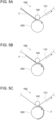
- a direction of rotation of the medium 500 is such a direction that movement of the circumferential surface matches the transfer direction of the intermediate transfer belt 131 at a position where the intermediate transfer belt 131 and the circumferential surface of the medium 500 make contact with each other.
- the medium 500 is illustrated in such a posture that the central axis of the circumferential surface is perpendicular to the paper on which Figs. 5A to 5C are drawn.
- the intermediate transfer belt 131 moves from left to right in Figs. 5A to 5C , and the medium 500 rotates in a clockwise direction in Figs. 5A to 5C (see the arrows in Figs. 5A to 5C ).
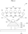
- the transfer unit 100 transfers the image T onto the medium 500
- the image T is formed on the intermediate transfer belt 131 by the developing devices 110 of the respective colors as the intermediate transfer belt 131 moves. Then, when the intermediate transfer belt 131 further moves and the image T formed on the intermediate transfer belt 131 reaches the transfer position, the image T is transferred from the intermediate transfer belt 131 onto the medium 500, as illustrated in Fig. 5A .
- the intermediate transfer belt 131 further moves, the medium 500 rotates accordingly, and transfer of the image T is executed while the contact portion of the medium 500 moves along the circumferential direction. Accordingly, the image T on the intermediate transfer belt 131 is transferred onto the circumferential surface of the medium 500 along the circumferential direction, as illustrated in Figs. 5B and 5C .
- the jig 423 for the medium 500 having the circumferential surface is described.
- the jig 423 that rotates the medium 500 and continuously brings the circumferential surface of the medium 500 into contact with the intermediate transfer belt 131 of the transfer unit 100 along the circumferential direction is used, as described with reference to Fig. 5 .
- a configuration of such a jig 423 is described below by giving specific examples.
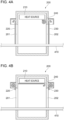
- Figs. 6A and 6B illustrate an example of a configuration of the jig 423 that rotatably holds the medium 500.
- Fig. 6A illustrates the jig 423 and the medium 500 viewed in a direction parallel with a rotary axis of the medium 500
- Fig. 6B illustrates a relationship between the medium 500 and rollers 423b of the jig 423 viewed in a direction perpendicular to the rotary axis of the medium 500.
- Fig. 6B only the medium 500 and the rollers 423b are illustrated.
- the jig 423 illustrated in Fig. 6A includes a base 423a and the rollers 423b.
- the base 423a includes a driving device 423c for rotating the rollers 423b.
- the base 423a has a structure that fits with the fastener of the table part 422 and is fixed to the table part 422.
- the rollers 423b make contact with the circumferential surface of the medium 500 and rotatably supports the medium 500.
- the rollers 423b are disposed on the base 423a so that rotary axes thereof are orthogonal to the transfer direction of the intermediate transfer belt 131 and the medium 500 is placed on the rollers 423b.
- two rollers 423b are spaced apart from each other by an appropriate distance so that rotary axes thereof are parallel with each other, and the medium 500 is placed between the two rollers 423b.
- a rotary surface of each of the rollers 423b is, for example, made of a member having a high coefficient of friction such as rubber.
- the image forming apparatus 10 rotates the medium 500 at the transfer position when an image is formed on the medium 500, as described with reference to Fig. 5 . Accordingly, in some cases, a portion of the circumferential surface of the medium 500 onto which the image has been transferred moves downward and reaches a position corresponding to the rollers 423b as the medium 500 rotates.
- An example of such cases is a case where an image is transferred over a half of the circumference or an entire circumference of the circumferential surface of the medium 500. In such a case, it is necessary to avoid contact between the image transferred onto the circumferential surface of the medium 500 and the rollers 423b.
- the rollers 423b are configured to support the medium 500 in regions other than a region where an image is to be transferred on the circumferential surface of the medium 500.
- a region R where an image is to be transferred is set in a central part of the circumferential surface of the medium 500 in a central axis direction.
- Two rollers 423b whose rotary axes match each other are disposed on both sides of the region R so as to support the medium 500 at positions that do not make contact with the region R.
- the configuration illustrated in Fig. 6B is an example of a configuration in which the rollers 423b do not make contact with the region R of the medium 500, and shapes of the rollers 423b are not limited to the configuration illustrated in Fig. 6B .
- a roller 423b whose portion corresponding to the region R is thinner than portions thereof on both sides and does not make contact with the region R may be used instead of disposing the plural rollers 423b as illustrated in Fig. 6B .
- the driving device 423c is a driving unit for rotating the rollers 423b.
- the rollers 423b rotate by receiving power from the driving device 423c and thereby rotates the medium 500.
- Any of various existing mechanisms can be used as the driving device 423c, and a specific structure of the driving device 423c is not limited.
- a motor and a driving roller that rotates by receiving power from the motor may be used, and rotation of the driving roller may be transmitted to the rollers 423b by bringing the driving roller into contact with the rollers 423b.
- the medium 500 is made of a material having a high coefficient of friction with the intermediate transfer belt 131
- the medium 500 is rotated without the need for driving by the rollers 423b by being pulled by the intermediate transfer belt 131 at the contact position.
- Figs. 7A and 7B illustrate another example of the configuration of the jig 423 that rotatably holds the medium 500.
- Fig. 7A illustrates the jig 423 and the medium 500 viewed in a direction parallel with the rotary axis of the medium 500
- Fig. 7B illustrates the jig 423 and the medium 500 viewed in a direction perpendicular to the rotary axis of the medium 500.
- the jig 423 illustrated in Figs. 7A and 7B supports the medium 500 so that the medium 500 is rotatable about the central axis of the circumferential surface of the medium 500.
- the jig 423 has fastening parts 423d that rotatably fasten the medium 500.
- the jig 423 includes a driving device 423e for rotating the medium 500.
- the jig 423 has a structure that fits with the fastener of the table part 422 and is fixed to the table part 422.
- the jig 423 illustrated in Figs. 7A and 7B fastens positions where the central axis of the circumferential surface of the medium 500 passes from both sides of the axis by using the fastening parts 423d.
- the driving device 423e is a driving unit for rotating the fastening parts 423d.
- the fastening parts 423d receives power from the driving device 423e and rotate the medium 500 about the central axis of the circumferential surface while fastening the medium 500.
- Any of various existing mechanisms can be used as the driving device 423e, and a specific structure of the driving device 423e is not limited.
- the fastening parts 423d may be directly driven to rotate by a motor.
- the driving device 423e rotates the fastening parts 423d so that a rotation speed of the medium 500 becomes equal to a moving speed of the intermediate transfer belt 131 at the contact position with the intermediate transfer belt 131 of the transfer unit 100.
- the configuration in which the driving device 423e is provided in the jig 423 and the jig 423 dynamically rotates the medium 500 in synchronization with action of the intermediate transfer belt 131 of the transfer unit 100 while using the fastening parts 423d as driving wheels has been described.
- the jig 423 merely rotatably supports the medium 500 and the medium 500 rotates in accordance with action of the intermediate transfer belt 131 while the fastening parts 423d are used as driven wheels.
- the medium 500 is made of a material having a high coefficient of friction with the intermediate transfer belt 131, the medium 500 is rotated without the need for driving by the fastening part 423d by being pulled by the intermediate transfer belt 131 at the contact position.
- the jig 423 illustrated in Figs. 7A and 7B rotates while fastening the central axis of the circumferential surface of the medium 500, media 500 having various shapes having a circumferential surface can be held by fastening the central axis of the circumferential surface. Furthermore, the jig 423 illustrated in Figs. 7A and 7B can hold the medium 500 so that an image is transferred onto a circumferential surface of the medium 500 even in a case where the circumferential surface of the medium 500 has an uneven portion.
- Figs. 8A and 8B illustrate an example of the medium 500 having a circumferential surface.
- Fig. 8A illustrates a medium 500 having a spherical shape
- Fig. 8B illustrates a medium 500 having a truncated cone shape.
- Figs. 8A and 8B illustrate the medium 500 viewed in a direction perpendicular to the rotary axis of the medium 500 from a front side in the transport direction in which the medium 500 is transported.
- the circumferential surface is bulged not only in a circumferential direction, but also in a direction parallel with the central axis. Accordingly, an image is transferred onto a thin region where the medium 500 and the intermediate transfer belt 131 make contact with each other due to warpage of the intermediate transfer belt 131, as illustrated in Fig. 8A .
- an image of this width can be transferred over an entire circumference of the spherical medium 500.
- a band-shaped image T is formed on a portion of the surface of the medium 500 that makes contact with the intermediate transfer belt 131.
- the jig 423 is fixed to the attachment table 420 with the use of the fastener provided on the table part 422.
- the table part 422 is provided with a movement path, and the jig 423 has a unit for movement that moves along the movement path.
- the movement path of the table part 422 and the unit for movement of the jig 423 are not limited to a specific configuration, provided that the jig 423 can move along a predetermined movement path.
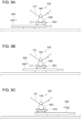
- Figs. 9A to 9C illustrate movement of the jig 423.
- Fig. 9A illustrates a state at the start of transfer
- Fig. 9B illustrates a state during the transfer
- Fig. 9C illustrates a state at the end of the transfer.
- the jig 423 starts moving on the table part 422 in a direction opposite to the transport direction in which the attachment table 420 is transported, as illustrated in Fig. 9A .
- the jig 423 moves on the table part 422 and keeps the medium 500 at the transfer position as illustrated in Fig. 9B as the image is transferred onto the medium 500.
- the movement of the jig 423 ends, and the medium 500 is transported toward the fixing unit 200 together with the attachment table 420, as illustrated in Fig. 9C .
Landscapes
- Physics & Mathematics (AREA)
- General Physics & Mathematics (AREA)
- Engineering & Computer Science (AREA)
- Manufacturing & Machinery (AREA)
- Ceramic Engineering (AREA)
- Textile Engineering (AREA)
- Electrostatic Charge, Transfer And Separation In Electrography (AREA)
- Feeding Of Articles By Means Other Than Belts Or Rollers (AREA)
Claims (8)
- Appareil de formation d'images (10) comprenant :une unité de transfert (100) configurée pour transférer une image sur un objet (500) en entrant en contact avec l'objet (500) ;une unité de maintien (420) configurée pour maintenir l'objet (500) ayant une surface circonférentielle de sorte que la surface circonférentielle tourne le long d'une direction de transfert de l'unité de transfert (100) ;une unité de fixation (200) configurée pour fixer sur la surface circonférentielle de l'objet (500), l'image transférée par l'unité de transfert (100) en chauffant l'objet (500) ; etune unité de transport (400) configurée pour transporter l'unité de maintien (420) maintenant l'objet (500) le long d'un chemin de transport,dans lequel l'unité de maintien (420) inclut un gabarit (423) configuré pour supporter l'objet (500) placé dessus,l'appareil de formation d'images (10) étant caractérisé en ce que :
l'unité de transfert (100) est configurée pour transférer l'image sur la surface circonférentielle de l'objet (500) dans une direction circonférentielle à mesure que l'objet (500) tourne autour d'un axe central de la surface circonférentielle de l'objet (500), en entrant en contact avec la surface circonférentielle de l'objet (500) maintenue à une position de transfert, et que le gabarit (423) maintient l'objet (500) de sorte que l'axe central de la surface circonférentielle de l'objet (500) est orthogonal à la direction de transfert de l'unité de transfert (100) à la position de transfert. - Appareil de formation d'images (10) selon la revendication 1, dans lequel :
l'unité de maintien (420) inclut en outre une partie de table mobile (421, 422) qui est déplacée le long du chemin de transport par l'unité de transport (400), et le gabarit (423) est prévu sur la partie de table mobile (421, 422) de manière à être mobile dans une direction opposée à la direction de transport de l'unité de transport (400) et supporte de manière rotative l'objet (500). - Appareil de formation d'images (10) selon la revendication 2, dans lequel :
l'unité de maintien (420) inclut en outre un mécanisme d'entraînement configuré pour déplacer le gabarit (423) par rapport à la partie de table mobile (421, 422) à une même vitesse qu'une vitesse de transport de l'unité de transport (400) dans la direction opposée à la direction de transport de l'unité de transport (400). - Appareil de formation d'images (10) selon l'une quelconque des revendications 1 à 3, dans lequel :
le gabarit (423) est pourvu d'un rouleau (423b) qui a un axe de rotation sensiblement orthogonal à la direction de transport de l'unité de transport (400) et supporte la surface circonférentielle de l'objet (500). - Appareil de formation d'images (10) selon la revendication 4, dans lequel :
le rouleau (423b) du gabarit (423) est prévu de manière à supporter l'objet (500) dans une région de l'objet (500) autre qu'une région d'image (R) où une image doit être transférée. - Appareil de formation d'images (10) selon la revendication 4 ou la revendication 5, dans lequel :
le gabarit (423) inclut une unité d'entraînement (423e) configurée pour faire tourner le rouleau (423b) de sorte que l'objet (500) tourne à une vitesse correspondant à une vitesse de transfert à laquelle une image est transférée par l'unité de transfert (100). - Appareil de formation d'images (10) selon l'une quelconque des revendications 1 à 3, dans lequel :
le gabarit (423) est configuré pour supporter l'objet (500) de sorte que l'objet (500) soit rotatif autour de l'axe central de la surface circonférentielle de l'objet (500) incluant une région d'image (R) où une image doit être transférée. - Appareil de formation d'images (10) selon la revendication 7, comprenant en outre une unité d'entraînement configurée pour entraîner le gabarit (423) de sorte que l'objet (500) tourne à une vitesse correspondant à une vitesse de transfert à laquelle une image est transférée par l'unité de transfert (100).
Applications Claiming Priority (1)
| Application Number | Priority Date | Filing Date | Title |
|---|---|---|---|
| JP2022103393A JP2024003990A (ja) | 2022-06-28 | 2022-06-28 | 画像形成装置 |
Publications (2)
| Publication Number | Publication Date |
|---|---|
| EP4300196A1 EP4300196A1 (fr) | 2024-01-03 |
| EP4300196B1 true EP4300196B1 (fr) | 2025-07-09 |
Family
ID=85726515
Family Applications (1)
| Application Number | Title | Priority Date | Filing Date |
|---|---|---|---|
| EP23163601.0A Active EP4300196B1 (fr) | 2022-06-28 | 2023-03-23 | Appareil de formation d'images |
Country Status (4)
| Country | Link |
|---|---|
| US (1) | US11960222B2 (fr) |
| EP (1) | EP4300196B1 (fr) |
| JP (1) | JP2024003990A (fr) |
| CN (1) | CN117311115A (fr) |
Families Citing this family (4)
| Publication number | Priority date | Publication date | Assignee | Title |
|---|---|---|---|---|
| JP2024003996A (ja) * | 2022-06-28 | 2024-01-16 | 富士フイルムビジネスイノベーション株式会社 | 画像形成システム |
| JP2024139397A (ja) * | 2023-03-27 | 2024-10-09 | 富士フイルムビジネスイノベーション株式会社 | 保持装置、定着装置、画像形成システム |
| JP2025139456A (ja) * | 2024-03-12 | 2025-09-26 | 富士フイルムビジネスイノベーション株式会社 | 定着装置及び画像形成装置 |
| JP2025140107A (ja) * | 2024-03-13 | 2025-09-29 | 富士フイルムビジネスイノベーション株式会社 | 定着装置及び画像形成装置 |
Family Cites Families (20)
| Publication number | Priority date | Publication date | Assignee | Title |
|---|---|---|---|---|
| US4142462A (en) * | 1977-05-11 | 1979-03-06 | International Paper Company | Halftone printing method |
| US4519310A (en) * | 1981-04-27 | 1985-05-28 | Daiwa Can Company, Limited | Method of multi-color printing on cylindrical container |
| US5065183A (en) * | 1987-10-02 | 1991-11-12 | Toyo Seikan Kaisha, Ltd. | Multicolor printing method for container |
| IL113552A (en) * | 1995-04-30 | 2005-09-25 | Hewlett Packard Indigo Bv | Apparatus and method for centerless printing of images particularly on cylindrical objects |
| WO1998029784A1 (fr) | 1996-12-27 | 1998-07-09 | Kao Corporation | Procede d'impression, imprimante, imprimes et disque optique |
| US6556803B2 (en) * | 2000-07-28 | 2003-04-29 | Tohoku Ricoh Co., Ltd. | Image forming apparatus for synthetic resin sheets |
| US6570600B2 (en) * | 2001-01-19 | 2003-05-27 | Impress Systems | Method and apparatus for direct cylinder printer |
| DE10225198B4 (de) * | 2002-06-06 | 2007-07-12 | Polytype S.A. | Verfahren und Vorrichtung zum Drucken eines mehrfarbigen Bildes |
| JP4220279B2 (ja) | 2003-03-14 | 2009-02-04 | 株式会社日立プラントテクノロジー | フレキソ印刷装置とこれを用いた液晶表示装置の製造方法 |
| DE102006031304B8 (de) * | 2006-07-06 | 2008-10-02 | Schott Ag | Verfahren zum Bedrucken eines Behälters |
| FR2905630B1 (fr) * | 2006-09-12 | 2010-01-22 | Impika | Dispositif d'impression par transfert sur un support d'impression cylindrique |
| CN205291622U (zh) | 2016-01-16 | 2016-06-08 | 曾志文 | 一种打印回转体的3d打印机 |
| US10046512B2 (en) | 2016-04-14 | 2018-08-14 | Xerox Corporation | Electro-photographic 3-D printing using dissolvable paper |
| US10105902B2 (en) | 2016-04-18 | 2018-10-23 | Evolve Additive Solutions, Inc. | Electrophotography-based additive manufacturing with part molding |
| US10739705B2 (en) * | 2016-08-10 | 2020-08-11 | Ball Corporation | Method and apparatus of decorating a metallic container by digital printing to a transfer blanket |
| JP6900650B2 (ja) | 2016-10-17 | 2021-07-07 | 富士フイルムビジネスイノベーション株式会社 | 画像形成装置、及び画像形成方法 |
| US10682837B2 (en) * | 2017-06-09 | 2020-06-16 | The Proctor & Gamble Company | Method and compositions for applying a material onto articles |
| EP3682228B1 (fr) | 2017-09-11 | 2025-12-17 | Faxitron Bioptics, LLC | Système d'imagerie à grossissement d'objet adaptatif |
| GB2577086B (en) * | 2018-09-13 | 2022-02-23 | Landa Labs 2012 Ltd | Printing on cylindrical objects |
| DE102019124759A1 (de) * | 2019-09-13 | 2021-03-18 | Tampoprint Ag | Vorrichtung und Verfahren zum indirekten Bedrucken abrollbarer Teile |
-
2022
- 2022-06-28 JP JP2022103393A patent/JP2024003990A/ja active Pending
- 2022-11-15 US US17/987,807 patent/US11960222B2/en active Active
-
2023
- 2023-01-03 CN CN202310001129.3A patent/CN117311115A/zh active Pending
- 2023-03-23 EP EP23163601.0A patent/EP4300196B1/fr active Active
Also Published As
| Publication number | Publication date |
|---|---|
| JP2024003990A (ja) | 2024-01-16 |
| US20230418190A1 (en) | 2023-12-28 |
| CN117311115A (zh) | 2023-12-29 |
| EP4300196A1 (fr) | 2024-01-03 |
| US11960222B2 (en) | 2024-04-16 |
Similar Documents
| Publication | Publication Date | Title |
|---|---|---|
| EP4300196B1 (fr) | Appareil de formation d'images | |
| CN108303867A (zh) | 定影装置 | |
| US5428430A (en) | Image forming method and apparatus using an intermediate | |
| EP4300205B1 (fr) | Appareil de formation d'images | |
| US8649721B2 (en) | Processing apparatus and cartridge | |
| EP0453219B1 (fr) | Méthode de transfert d'images pour une imprimante électrographique | |
| EP4300206B1 (fr) | Appareil de formation d'images | |
| EP4300198B1 (fr) | Appareil de formation d'images | |
| EP4300208B1 (fr) | Appareil de formation d'images | |
| EP4300195B1 (fr) | Appareil de formation d'images | |
| EP4300197B1 (fr) | Appareil de formation d'images | |
| EP4435529A1 (fr) | Appareil de formation d'images | |
| CN121432828A (zh) | 图像形成装置 | |
| JPH0232374A (ja) | 画像形成装置 | |
| JP2004012822A (ja) | 定着装置及びこの定着装置を備える画像形成装置 |
Legal Events
| Date | Code | Title | Description |
|---|---|---|---|
| PUAI | Public reference made under article 153(3) epc to a published international application that has entered the european phase |
Free format text: ORIGINAL CODE: 0009012 |
|
| STAA | Information on the status of an ep patent application or granted ep patent |
Free format text: STATUS: THE APPLICATION HAS BEEN PUBLISHED |
|
| AK | Designated contracting states |
Kind code of ref document: A1 Designated state(s): AL AT BE BG CH CY CZ DE DK EE ES FI FR GB GR HR HU IE IS IT LI LT LU LV MC ME MK MT NL NO PL PT RO RS SE SI SK SM TR |
|
| STAA | Information on the status of an ep patent application or granted ep patent |
Free format text: STATUS: REQUEST FOR EXAMINATION WAS MADE |
|
| 17P | Request for examination filed |
Effective date: 20240531 |
|
| RBV | Designated contracting states (corrected) |
Designated state(s): AL AT BE BG CH CY CZ DE DK EE ES FI FR GB GR HR HU IE IS IT LI LT LU LV MC ME MK MT NL NO PL PT RO RS SE SI SK SM TR |
|
| STAA | Information on the status of an ep patent application or granted ep patent |
Free format text: STATUS: EXAMINATION IS IN PROGRESS |
|
| 17Q | First examination report despatched |
Effective date: 20240812 |
|
| GRAP | Despatch of communication of intention to grant a patent |
Free format text: ORIGINAL CODE: EPIDOSNIGR1 |
|
| STAA | Information on the status of an ep patent application or granted ep patent |
Free format text: STATUS: GRANT OF PATENT IS INTENDED |
|
| INTG | Intention to grant announced |
Effective date: 20250310 |
|
| GRAS | Grant fee paid |
Free format text: ORIGINAL CODE: EPIDOSNIGR3 |
|
| GRAA | (expected) grant |
Free format text: ORIGINAL CODE: 0009210 |
|
| STAA | Information on the status of an ep patent application or granted ep patent |
Free format text: STATUS: THE PATENT HAS BEEN GRANTED |
|
| AK | Designated contracting states |
Kind code of ref document: B1 Designated state(s): AL AT BE BG CH CY CZ DE DK EE ES FI FR GB GR HR HU IE IS IT LI LT LU LV MC ME MK MT NL NO PL PT RO RS SE SI SK SM TR |
|
| REG | Reference to a national code |
Ref country code: GB Ref legal event code: FG4D |
|
| REG | Reference to a national code |
Ref country code: CH Ref legal event code: EP |
|
| REG | Reference to a national code |
Ref country code: IE Ref legal event code: FG4D |
|
| REG | Reference to a national code |
Ref country code: DE Ref legal event code: R096 Ref document number: 602023004607 Country of ref document: DE |
|
| REG | Reference to a national code |
Ref country code: NL Ref legal event code: MP Effective date: 20250709 |
|
| PG25 | Lapsed in a contracting state [announced via postgrant information from national office to epo] |
Ref country code: PT Free format text: LAPSE BECAUSE OF FAILURE TO SUBMIT A TRANSLATION OF THE DESCRIPTION OR TO PAY THE FEE WITHIN THE PRESCRIBED TIME-LIMIT Effective date: 20251110 |
|
| PG25 | Lapsed in a contracting state [announced via postgrant information from national office to epo] |
Ref country code: NL Free format text: LAPSE BECAUSE OF FAILURE TO SUBMIT A TRANSLATION OF THE DESCRIPTION OR TO PAY THE FEE WITHIN THE PRESCRIBED TIME-LIMIT Effective date: 20250709 |
|
| REG | Reference to a national code |
Ref country code: AT Ref legal event code: MK05 Ref document number: 1812376 Country of ref document: AT Kind code of ref document: T Effective date: 20250709 |
|
| PG25 | Lapsed in a contracting state [announced via postgrant information from national office to epo] |
Ref country code: IS Free format text: LAPSE BECAUSE OF FAILURE TO SUBMIT A TRANSLATION OF THE DESCRIPTION OR TO PAY THE FEE WITHIN THE PRESCRIBED TIME-LIMIT Effective date: 20251109 |
|
| PG25 | Lapsed in a contracting state [announced via postgrant information from national office to epo] |
Ref country code: NO Free format text: LAPSE BECAUSE OF FAILURE TO SUBMIT A TRANSLATION OF THE DESCRIPTION OR TO PAY THE FEE WITHIN THE PRESCRIBED TIME-LIMIT Effective date: 20251009 |
|
| REG | Reference to a national code |
Ref country code: LT Ref legal event code: MG9D |
|
| PG25 | Lapsed in a contracting state [announced via postgrant information from national office to epo] |
Ref country code: AT Free format text: LAPSE BECAUSE OF FAILURE TO SUBMIT A TRANSLATION OF THE DESCRIPTION OR TO PAY THE FEE WITHIN THE PRESCRIBED TIME-LIMIT Effective date: 20250709 |
|
| PG25 | Lapsed in a contracting state [announced via postgrant information from national office to epo] |
Ref country code: FI Free format text: LAPSE BECAUSE OF FAILURE TO SUBMIT A TRANSLATION OF THE DESCRIPTION OR TO PAY THE FEE WITHIN THE PRESCRIBED TIME-LIMIT Effective date: 20250709 |
|
| PG25 | Lapsed in a contracting state [announced via postgrant information from national office to epo] |
Ref country code: HR Free format text: LAPSE BECAUSE OF FAILURE TO SUBMIT A TRANSLATION OF THE DESCRIPTION OR TO PAY THE FEE WITHIN THE PRESCRIBED TIME-LIMIT Effective date: 20250709 |
|
| PG25 | Lapsed in a contracting state [announced via postgrant information from national office to epo] |
Ref country code: GR Free format text: LAPSE BECAUSE OF FAILURE TO SUBMIT A TRANSLATION OF THE DESCRIPTION OR TO PAY THE FEE WITHIN THE PRESCRIBED TIME-LIMIT Effective date: 20251010 |
|
| PG25 | Lapsed in a contracting state [announced via postgrant information from national office to epo] |
Ref country code: SE Free format text: LAPSE BECAUSE OF FAILURE TO SUBMIT A TRANSLATION OF THE DESCRIPTION OR TO PAY THE FEE WITHIN THE PRESCRIBED TIME-LIMIT Effective date: 20250709 |
|
| PG25 | Lapsed in a contracting state [announced via postgrant information from national office to epo] |
Ref country code: LV Free format text: LAPSE BECAUSE OF FAILURE TO SUBMIT A TRANSLATION OF THE DESCRIPTION OR TO PAY THE FEE WITHIN THE PRESCRIBED TIME-LIMIT Effective date: 20250709 |
|
| PG25 | Lapsed in a contracting state [announced via postgrant information from national office to epo] |
Ref country code: BG Free format text: LAPSE BECAUSE OF FAILURE TO SUBMIT A TRANSLATION OF THE DESCRIPTION OR TO PAY THE FEE WITHIN THE PRESCRIBED TIME-LIMIT Effective date: 20250709 Ref country code: PL Free format text: LAPSE BECAUSE OF FAILURE TO SUBMIT A TRANSLATION OF THE DESCRIPTION OR TO PAY THE FEE WITHIN THE PRESCRIBED TIME-LIMIT Effective date: 20250709 |
|
| PG25 | Lapsed in a contracting state [announced via postgrant information from national office to epo] |
Ref country code: RS Free format text: LAPSE BECAUSE OF FAILURE TO SUBMIT A TRANSLATION OF THE DESCRIPTION OR TO PAY THE FEE WITHIN THE PRESCRIBED TIME-LIMIT Effective date: 20251009 |
|
| PG25 | Lapsed in a contracting state [announced via postgrant information from national office to epo] |
Ref country code: ES Free format text: LAPSE BECAUSE OF FAILURE TO SUBMIT A TRANSLATION OF THE DESCRIPTION OR TO PAY THE FEE WITHIN THE PRESCRIBED TIME-LIMIT Effective date: 20250709 |
|
| P01 | Opt-out of the competence of the unified patent court (upc) registered |
Free format text: CASE NUMBER: UPC_APP_0000833_4300196/2026 Effective date: 20260109 |
|
| PG25 | Lapsed in a contracting state [announced via postgrant information from national office to epo] |
Ref country code: SM Free format text: LAPSE BECAUSE OF FAILURE TO SUBMIT A TRANSLATION OF THE DESCRIPTION OR TO PAY THE FEE WITHIN THE PRESCRIBED TIME-LIMIT Effective date: 20250709 |
|
| PG25 | Lapsed in a contracting state [announced via postgrant information from national office to epo] |
Ref country code: DK Free format text: LAPSE BECAUSE OF FAILURE TO SUBMIT A TRANSLATION OF THE DESCRIPTION OR TO PAY THE FEE WITHIN THE PRESCRIBED TIME-LIMIT Effective date: 20250709 |
|
| PGFP | Annual fee paid to national office [announced via postgrant information from national office to epo] |
Ref country code: DE Payment date: 20260128 Year of fee payment: 4 |
|
| PG25 | Lapsed in a contracting state [announced via postgrant information from national office to epo] |
Ref country code: IT Free format text: LAPSE BECAUSE OF FAILURE TO SUBMIT A TRANSLATION OF THE DESCRIPTION OR TO PAY THE FEE WITHIN THE PRESCRIBED TIME-LIMIT Effective date: 20250709 |
|
| PGFP | Annual fee paid to national office [announced via postgrant information from national office to epo] |
Ref country code: FR Payment date: 20260209 Year of fee payment: 4 |
|
| PG25 | Lapsed in a contracting state [announced via postgrant information from national office to epo] |
Ref country code: CZ Free format text: LAPSE BECAUSE OF FAILURE TO SUBMIT A TRANSLATION OF THE DESCRIPTION OR TO PAY THE FEE WITHIN THE PRESCRIBED TIME-LIMIT Effective date: 20250709 |
|
| PG25 | Lapsed in a contracting state [announced via postgrant information from national office to epo] |
Ref country code: SK Free format text: LAPSE BECAUSE OF FAILURE TO SUBMIT A TRANSLATION OF THE DESCRIPTION OR TO PAY THE FEE WITHIN THE PRESCRIBED TIME-LIMIT Effective date: 20250709 Ref country code: EE Free format text: LAPSE BECAUSE OF FAILURE TO SUBMIT A TRANSLATION OF THE DESCRIPTION OR TO PAY THE FEE WITHIN THE PRESCRIBED TIME-LIMIT Effective date: 20250709 |