EP4300207B1 - Bilderzeugungssystem und bilderzeugungsverfahren - Google Patents
Bilderzeugungssystem und bilderzeugungsverfahren Download PDFInfo
- Publication number
- EP4300207B1 EP4300207B1 EP23163377.7A EP23163377A EP4300207B1 EP 4300207 B1 EP4300207 B1 EP 4300207B1 EP 23163377 A EP23163377 A EP 23163377A EP 4300207 B1 EP4300207 B1 EP 4300207B1
- Authority
- EP
- European Patent Office
- Prior art keywords
- image
- medium
- onto
- transfer
- fixing
- Prior art date
- Legal status (The legal status is an assumption and is not a legal conclusion. Google has not performed a legal analysis and makes no representation as to the accuracy of the status listed.)
- Active
Links
Images






Classifications
-
- G—PHYSICS
- G03—PHOTOGRAPHY; CINEMATOGRAPHY; ANALOGOUS TECHNIQUES USING WAVES OTHER THAN OPTICAL WAVES; ELECTROGRAPHY; HOLOGRAPHY
- G03G—ELECTROGRAPHY; ELECTROPHOTOGRAPHY; MAGNETOGRAPHY
- G03G15/00—Apparatus for electrographic processes using a charge pattern
- G03G15/22—Apparatus for electrographic processes using a charge pattern involving the combination of more than one step according to groups G03G13/02 - G03G13/20
- G03G15/221—Machines other than electrographic copiers, e.g. electrophotographic cameras, electrostatic typewriters
- G03G15/224—Machines for forming tactile or three dimensional images by electrographic means, e.g. braille, 3d printing
-
- G—PHYSICS
- G03—PHOTOGRAPHY; CINEMATOGRAPHY; ANALOGOUS TECHNIQUES USING WAVES OTHER THAN OPTICAL WAVES; ELECTROGRAPHY; HOLOGRAPHY
- G03G—ELECTROGRAPHY; ELECTROPHOTOGRAPHY; MAGNETOGRAPHY
- G03G15/00—Apparatus for electrographic processes using a charge pattern
- G03G15/65—Apparatus which relate to the handling of copy material
- G03G15/6529—Transporting
-
- B—PERFORMING OPERATIONS; TRANSPORTING
- B41—PRINTING; LINING MACHINES; TYPEWRITERS; STAMPS
- B41J—TYPEWRITERS; SELECTIVE PRINTING MECHANISMS, i.e. MECHANISMS PRINTING OTHERWISE THAN FROM A FORME; CORRECTION OF TYPOGRAPHICAL ERRORS
- B41J3/00—Typewriters or selective printing or marking mechanisms characterised by the purpose for which they are constructed
- B41J3/407—Typewriters or selective printing or marking mechanisms characterised by the purpose for which they are constructed for marking on special material
-
- B—PERFORMING OPERATIONS; TRANSPORTING
- B41—PRINTING; LINING MACHINES; TYPEWRITERS; STAMPS
- B41M—PRINTING, DUPLICATING, MARKING, OR COPYING PROCESSES; COLOUR PRINTING
- B41M1/00—Inking and printing with a printer's forme
- B41M1/26—Printing on other surfaces than ordinary paper
-
- B—PERFORMING OPERATIONS; TRANSPORTING
- B41—PRINTING; LINING MACHINES; TYPEWRITERS; STAMPS
- B41M—PRINTING, DUPLICATING, MARKING, OR COPYING PROCESSES; COLOUR PRINTING
- B41M5/00—Duplicating or marking methods; Sheet materials for use therein
- B41M5/0041—Digital printing on surfaces other than ordinary paper
-
- G—PHYSICS
- G03—PHOTOGRAPHY; CINEMATOGRAPHY; ANALOGOUS TECHNIQUES USING WAVES OTHER THAN OPTICAL WAVES; ELECTROGRAPHY; HOLOGRAPHY
- G03G—ELECTROGRAPHY; ELECTROPHOTOGRAPHY; MAGNETOGRAPHY
- G03G15/00—Apparatus for electrographic processes using a charge pattern
- G03G15/20—Apparatus for electrographic processes using a charge pattern for fixing, e.g. by using heat
- G03G15/2003—Apparatus for electrographic processes using a charge pattern for fixing, e.g. by using heat using heat
- G03G15/2007—Apparatus for electrographic processes using a charge pattern for fixing, e.g. by using heat using heat using radiant heat, e.g. infrared lamps, microwave heaters
-
- G—PHYSICS
- G03—PHOTOGRAPHY; CINEMATOGRAPHY; ANALOGOUS TECHNIQUES USING WAVES OTHER THAN OPTICAL WAVES; ELECTROGRAPHY; HOLOGRAPHY
- G03G—ELECTROGRAPHY; ELECTROPHOTOGRAPHY; MAGNETOGRAPHY
- G03G15/00—Apparatus for electrographic processes using a charge pattern
- G03G15/20—Apparatus for electrographic processes using a charge pattern for fixing, e.g. by using heat
- G03G15/2003—Apparatus for electrographic processes using a charge pattern for fixing, e.g. by using heat using heat
- G03G15/2007—Apparatus for electrographic processes using a charge pattern for fixing, e.g. by using heat using heat using radiant heat, e.g. infrared lamps, microwave heaters
- G03G15/201—Apparatus for electrographic processes using a charge pattern for fixing, e.g. by using heat using heat using radiant heat, e.g. infrared lamps, microwave heaters of high intensity and short duration, i.e. flash fusing
-
- G—PHYSICS
- G03—PHOTOGRAPHY; CINEMATOGRAPHY; ANALOGOUS TECHNIQUES USING WAVES OTHER THAN OPTICAL WAVES; ELECTROGRAPHY; HOLOGRAPHY
- G03G—ELECTROGRAPHY; ELECTROPHOTOGRAPHY; MAGNETOGRAPHY
- G03G15/00—Apparatus for electrographic processes using a charge pattern
- G03G15/20—Apparatus for electrographic processes using a charge pattern for fixing, e.g. by using heat
- G03G15/2003—Apparatus for electrographic processes using a charge pattern for fixing, e.g. by using heat using heat
- G03G15/2014—Apparatus for electrographic processes using a charge pattern for fixing, e.g. by using heat using heat using contact heat
- G03G15/2017—Structural details of the fixing unit in general, e.g. cooling means, heat shielding means
- G03G15/2032—Retractable heating or pressure unit
-
- G—PHYSICS
- G03—PHOTOGRAPHY; CINEMATOGRAPHY; ANALOGOUS TECHNIQUES USING WAVES OTHER THAN OPTICAL WAVES; ELECTROGRAPHY; HOLOGRAPHY
- G03G—ELECTROGRAPHY; ELECTROPHOTOGRAPHY; MAGNETOGRAPHY
- G03G15/00—Apparatus for electrographic processes using a charge pattern
- G03G15/20—Apparatus for electrographic processes using a charge pattern for fixing, e.g. by using heat
- G03G15/2003—Apparatus for electrographic processes using a charge pattern for fixing, e.g. by using heat using heat
- G03G15/2014—Apparatus for electrographic processes using a charge pattern for fixing, e.g. by using heat using heat using contact heat
- G03G15/2039—Apparatus for electrographic processes using a charge pattern for fixing, e.g. by using heat using heat using contact heat with means for controlling the fixing temperature
- G03G15/205—Apparatus for electrographic processes using a charge pattern for fixing, e.g. by using heat using heat using contact heat with means for controlling the fixing temperature specially for the mode of operation, e.g. standby, warming-up, error
-
- G—PHYSICS
- G03—PHOTOGRAPHY; CINEMATOGRAPHY; ANALOGOUS TECHNIQUES USING WAVES OTHER THAN OPTICAL WAVES; ELECTROGRAPHY; HOLOGRAPHY
- G03G—ELECTROGRAPHY; ELECTROPHOTOGRAPHY; MAGNETOGRAPHY
- G03G15/00—Apparatus for electrographic processes using a charge pattern
- G03G15/65—Apparatus which relate to the handling of copy material
- G03G15/6555—Handling of sheet copy material taking place in a specific part of the copy material feeding path
- G03G15/657—Feeding path after the transfer point and up to the fixing point, e.g. guides and feeding means for handling copy material carrying an unfused toner image
-
- G—PHYSICS
- G03—PHOTOGRAPHY; CINEMATOGRAPHY; ANALOGOUS TECHNIQUES USING WAVES OTHER THAN OPTICAL WAVES; ELECTROGRAPHY; HOLOGRAPHY
- G03G—ELECTROGRAPHY; ELECTROPHOTOGRAPHY; MAGNETOGRAPHY
- G03G15/00—Apparatus for electrographic processes using a charge pattern
- G03G15/65—Apparatus which relate to the handling of copy material
- G03G15/6588—Apparatus which relate to the handling of copy material characterised by the copy material, e.g. postcards, large copies, multi-layered materials, coloured sheet material
- G03G15/6591—Apparatus which relate to the handling of copy material characterised by the copy material, e.g. postcards, large copies, multi-layered materials, coloured sheet material characterised by the recording material, e.g. plastic material, OHP, ceramics, tiles, textiles
-
- G—PHYSICS
- G03—PHOTOGRAPHY; CINEMATOGRAPHY; ANALOGOUS TECHNIQUES USING WAVES OTHER THAN OPTICAL WAVES; ELECTROGRAPHY; HOLOGRAPHY
- G03G—ELECTROGRAPHY; ELECTROPHOTOGRAPHY; MAGNETOGRAPHY
- G03G21/00—Arrangements not provided for by groups G03G13/00 - G03G19/00, e.g. cleaning, elimination of residual charge
- G03G21/16—Mechanical means for facilitating the maintenance of the apparatus, e.g. modular arrangements
- G03G21/1661—Mechanical means for facilitating the maintenance of the apparatus, e.g. modular arrangements means for handling parts of the apparatus in the apparatus
- G03G21/168—Mechanical means for facilitating the maintenance of the apparatus, e.g. modular arrangements means for handling parts of the apparatus in the apparatus for the transfer unit
-
- G—PHYSICS
- G03—PHOTOGRAPHY; CINEMATOGRAPHY; ANALOGOUS TECHNIQUES USING WAVES OTHER THAN OPTICAL WAVES; ELECTROGRAPHY; HOLOGRAPHY
- G03G—ELECTROGRAPHY; ELECTROPHOTOGRAPHY; MAGNETOGRAPHY
- G03G21/00—Arrangements not provided for by groups G03G13/00 - G03G19/00, e.g. cleaning, elimination of residual charge
- G03G21/16—Mechanical means for facilitating the maintenance of the apparatus, e.g. modular arrangements
- G03G21/1661—Mechanical means for facilitating the maintenance of the apparatus, e.g. modular arrangements means for handling parts of the apparatus in the apparatus
- G03G21/1695—Mechanical means for facilitating the maintenance of the apparatus, e.g. modular arrangements means for handling parts of the apparatus in the apparatus for paper transport
-
- B—PERFORMING OPERATIONS; TRANSPORTING
- B41—PRINTING; LINING MACHINES; TYPEWRITERS; STAMPS
- B41P—INDEXING SCHEME RELATING TO PRINTING, LINING MACHINES, TYPEWRITERS, AND TO STAMPS
- B41P2217/00—Printing machines of special types or for particular purposes
- B41P2217/50—Printing presses for particular purposes
- B41P2217/56—Printing presses for particular purposes for printing ceramic tiles
-
- G—PHYSICS
- G03—PHOTOGRAPHY; CINEMATOGRAPHY; ANALOGOUS TECHNIQUES USING WAVES OTHER THAN OPTICAL WAVES; ELECTROGRAPHY; HOLOGRAPHY
- G03G—ELECTROGRAPHY; ELECTROPHOTOGRAPHY; MAGNETOGRAPHY
- G03G15/00—Apparatus for electrographic processes using a charge pattern
- G03G15/01—Apparatus for electrographic processes using a charge pattern for producing multicoloured copies
- G03G15/0142—Structure of complete machines
- G03G15/0178—Structure of complete machines using more than one reusable electrographic recording member, e.g. one for every monocolour image
- G03G15/0189—Structure of complete machines using more than one reusable electrographic recording member, e.g. one for every monocolour image primary transfer to an intermediate transfer belt
-
- G—PHYSICS
- G03—PHOTOGRAPHY; CINEMATOGRAPHY; ANALOGOUS TECHNIQUES USING WAVES OTHER THAN OPTICAL WAVES; ELECTROGRAPHY; HOLOGRAPHY
- G03G—ELECTROGRAPHY; ELECTROPHOTOGRAPHY; MAGNETOGRAPHY
- G03G2215/00—Apparatus for electrophotographic processes
- G03G2215/00362—Apparatus for electrophotographic processes relating to the copy medium handling
- G03G2215/00443—Copy medium
- G03G2215/00523—Other special types, e.g. tabbed
Definitions
- the present disclosure relates to an image forming system and an image forming method.
- images may be printed, for example, on metal, glass, and tile (hereinafter referred to as "objects").
- objects have various thicknesses and shapes. Therefore, the image quality of the objects needs to be checked, and the settings of the objects need to be adjusted.
- EP 3 964 365 A1 discloses a transportation device including a first transporter, a second transporter movable between a contact position and a separate position toward and away from the first transporter to hold a to-be-transported object between the second transporter and the first transporter in the contact position, and a transportation unit that transports the to-be-transported object to a nip area where the first transporter and the second transporter hold the to-be-transported object therebetween while the second transporter is located in the separate position.
- US 5 359 400 A discloses an image forming apparatus with a sheet supply cassette which can contain a plurality of recording members and can be removably mounted within the image forming apparatus, an image forming device for forming an image on the recording member with toner to form a toner image, fixing rollers having a heater for thermally fixing the toner image on the recording member, remaining amount detecter means.
- JP S59 91471 A discloses an electrophotographic machine having a transfer paper fixing mode and an unfixing mode. When a toner image is fixed on transfer paper, a discharge part is placed in a state that the upper surface of a transportation belt and a discharge roll, and the upper surface of the transportation belt are not positioned on the same plane, and a control circuit attain a fixing mode.
- KR 2003 0026639 A discloses a composite image forming apparatus employing a combination of an inkjet printing method and an electrophotographic printing method and a printing method using the same.
- US 6 205 297 B1 discloses a recording apparatus having an emergency stop function for stopping the driving of the recording apparatus from the outside. When an instruction for an emergency stop is received during the paper transporting operation, a process is immediately performed by regarding a jam.
- claims 1 and 5 each enable reduction of wasteful objects compared with the case in which a transferred image is fixed onto an object even in the image-quality adjustment mode.
- the subject-matter of claim 2 enables reliable avoidance of an unintended operation of fixing an image.
- claims 1 and 5 each further enable a worker not to need to specify the adjustment mode.
- an object to be printed on is referred to as a medium 500.
- the material of a medium 500 is, for example, metal, glass, tile, ceramic, or wood, and has a standardized size. That is, the image forming apparatus 10 in the first exemplary embodiment forms images, one by one, on the surfaces of media 500 having the same material and shape.
- Fig. 1 illustrates the case of a flat-shaped medium 500.
- a plane defined by the X axis and the Y axis in the figures is horizontal to the floor.
- transporting a medium 500 in the X-axis direction is referred to as "transporting in the horizontal direction”.
- the image forming apparatus 10 illustrated in Fig. 1 includes three housings 10A, 10B, and 10C.
- the image forming apparatus 10 may appear as if it has a single housing.
- the housing 10A contains a transfer unit 100 and a processing unit 400.
- the housing 10B contains a fixing unit 200.
- the housing 10C is provided to take in and out a medium 500. To do this, an opening (not illustrated) is disposed on the top surface of the housing 10C.
- the image forming apparatus 10 includes a transporter 300 which extends across the three housings 10A, 10B, and 10C.
- the transporter 300 is an exemplary transporter.
- the transfer unit 100 transfers, onto a medium 500, an image formed by using toner or powder particles. That is, the transfer unit 100 in the first exemplary embodiment forms an image by using an electrophotographic system.
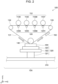
- Fig. 2 is a diagram illustrating an exemplary configuration of the transfer unit 100.
- the transfer unit 100 forms an image with charged particles, and generates an electric field to transfer the image onto a medium 500.
- the transfer unit 100 includes developing devices 110, first-transfer rolls 120, and an intermediate transfer belt 131.
- the intermediate transfer belt 131 which is stretched around driving rolls 132 and 133 and a backup roll 140, travels cyclically.
- the transfer unit 100 has a cleaning device 150 which removes particles having been attached to the intermediate transfer belt 131.
- Each developing device 110 is a unit which forms an electrostatic latent image of an image on its photoreceptor, and which attaches charged particles to the electrostatic latent image on the photoreceptor to develop the image.
- the developing devices 110 illustrated in Fig. 2 support four colors, which are black as well as three colors of yellow, magenta, and cyan.
- Fig. 2 units corresponding to the colors of yellow, magenta, cyan, and black are labeled with Y, M, C, and K indicating the respective colors.
- the units are not labeled with Y, M, C, and K.
- the first-transfer rolls 120 are used to transfer, onto the intermediate transfer belt 131, images formed on the developing devices 110.
- the transfer using the first-transfer rolls 120 is called "first transfer”.
- the first-transfer rolls 120 are disposed so as to be opposite the respective developing devices 110 with the intermediate transfer belt 131 interposed in between.
- the first-transfer rolls 120 bring the outer surface of the intermediate transfer belt 131 in contact with the developing devices 110.
- Fig. 2 images formed by the developing devices 110 are transferred onto the outer surface of the intermediate transfer belt 131. That is, the intermediate transfer belt 131 holds formed images.
- the outer surface of the intermediate transfer belt 131 is referred to as a "transfer surface”.
- the intermediate transfer belt 131 passes the developing devices 110Y, 110M, 110C, and 110K sequentially so that a multicolor image, in which yellow, magenta, cyan, and black are stacked on the transfer surface from the bottom layer in this sequence, is formed.
- the cleaning device 150 is a unit which removes particles remaining on the transfer surface of the intermediate transfer belt 131 which has passed the transfer position.
- the cleaning device 150 is disposed between the transfer position and the developing device 110Y in the rotation direction of the intermediate transfer belt 131. In other words, the cleaning device 150 is disposed downstream of the transfer position and upstream of the developing device 110Y.
- the mount 320 on which a medium 500 is mounted, is transported from the housing 10C, in which one end portion is present, to the housing 10A, in which the other end portion is present. In the transport operation, an operation of adjusting the height of the top of the medium 500 to the elevation of the intermediate transfer belt 131 is also performed.
- the end portion of the transport rail 310 in the housing 10A is spaced apart from the transfer position by a predetermined distance.
- the distance refers to a minimum distance necessary to accelerate the mount 320, which is in the halt state, to a target speed. Actually, the speed of the mount 320 needs to be maintained at the target speed. Thus, not only the distance for acceleration but also the distance for checking if the mount 320 moves at the target speed is necessary.
- the target speed is the traveling speed of the intermediate transfer belt 131.
- the jig 323 may be fixed to the mounting surface regardless of the shape of the jig 323.
- the fastener makes an integral unit constituted by the jig 323 and the pedestal 322, achieving reduction of transfer misalignment of an image.
- a shape, a structure, or a mechanism, which is suitable to hold a medium 500 which is an object to be mounted, is provided on the top surface of the jig 323.
- a jig 323 may be prepared for each medium 500 which is an object to be mounted, or a jig 323 which may support multiple shapes and sizes may be prepared.
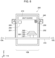
- the opening 201 is opened when a medium 500 is taken in/out between the housing 10A and the housing 10B, and is closed when a transferred image is to be fixed onto a medium 500.
- a heat source 210 is attached to the ceiling of the fixing unit 200.
- the heat source 210 may be attached, not limited to the ceiling, to a wall or both the ceiling and a wall.
- a halogen lamp, a ceramic heater, or an infrared lamp is used as the heat source 210.
- particles melted through heating are fixed onto the surface of a medium 500.
- a roll-up shutter 240 is attached between the heat source 210 and a space (hereinafter referred to as a "heating chamber") through which a medium 500 passes.
- Fig. 3 illustrates the state in which the roll-up shutter 240 is pulled out, that is, the state in which the heat source 210 is separated from the heating chamber.
- a material having the heat insulation property is used for the shutter 240.
- the heating chamber contains a temperature sensor 250.
- the ambient temperature measured by the temperature sensor 250 is output to the processing unit 400 (see Fig. 1 ).
- the processing unit 400 (see Fig. 1 ) is disposed in the housing 10A (see Fig. 1 ) in which the transfer unit 100 (see Fig. 1 ) is disposed.
- the processing unit 400 may be disposed in the housing 10B in which the fixing unit 200 (see Fig. 1 ) is disposed, or the housing 10C having the opening through which a medium 500 is taken in/out.
- the processing unit 400 may be provided for the housings 10A, 10B, and 10C of the image forming apparatus 10 as an external unit, or may be disposed on a network communicatively.
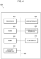
- Fig. 4 is a diagram for describing an exemplary configuration of the processing unit 400.
- the processing unit 400 includes a processor 410, a read only memory (ROM) 420 which stores, for example, a basic input output system (BIOS), a random access memory (RAM) 430 which is used as a work area of the processor 410, an auxiliary storage unit 440, a user interface 450, a communication interface 460, and an input/output (I/O) interface 470.
- the processor 410 is connected to the other devices through a bus or another signal line 480.
- the processor 410 is a device for implementing various functions through execution of programs.
- the processor 410, the ROM 420, and the RAM 430 function as a computer.
- the auxiliary storage unit 440 is contained in the housing 10A.
- the auxiliary storage unit 440 may be provided, as an external unit, for the housing 10A through the I/O interface 470, or may be a portable memory which may be attached to and detached from the housing 10A.
- the auxiliary storage unit 440 may be present on a network connected to the communication interface 460.
- the user interface 450 includes, for example, a touch panel, operation buttons, and a speaker which are used in display of an image for operation and in reception of operations.
- the touch panel is configured by a liquid-crystal display, an organic light-emitting diode (OLED) display, or another display, and an electrostatic-capacity sensor which detects a change in electrostatic capacity.
- OLED organic light-emitting diode
- the I/O interface 470 is an interface for communicating with the transfer unit 100 (see Fig. 1 ), the fixing unit 200 (see Fig. 1 ), and the transporter 300 (see Fig. 1 ).
- Fig. 5 is a diagram for describing an exemplary adjustment operation.
- a medium 500 which has been taken in through the opening of the housing 10C, is mounted on the mounting surface of the mount 320.
- the jig 323 is attached to the top surface of the pedestal 322, and the medium 500 is attached to the top surface of the jig 323.
- the height calibration P1 starts.
- the leg 321 is lowered from its initial position.
- the leg 321 is lowered in order that, when the mount 320 is horizontally moved to the intermediate transfer belt 131, the top of the medium 500 does not come in contact with the lower end of the intermediate transfer belt 131.
- the amount of lowering is predetermined. For example, the mount 320 is moved to the lowermost end of the movable range of the leg 321.
- the height of the mount 320 after the lowering is referred to as the "transport height".
- the mount 320 When the mount 320 is lowered to the transport height, transporting the mount 320 in the horizontal direction starts.
- the mount 320 passes through the fixing unit 200, and is transported to the position where the mount 320 faces the intermediate transfer belt 131.
- the leg 321 is raised, and the height (hereinafter also referred to as the "transfer height") at which the top of the medium 500 is in contact with the lower end of the intermediate transfer belt 131 is detected.
- This detection operation is referred to as the height calibration P1.
- the medium 500 which has been positioned at the transfer height, is pressed against the intermediate transfer belt 131 with a strength suitable for transfer.
- the transfer height is stored as the height of the leg 321 in the RAM 430 (see Fig. 4 ) or the auxiliary storage unit 440 (see Fig. 4 ) of the processing unit 400.
- the leg 321 is lowered again to the transport height so that the medium 500 is not in contact with the intermediate transfer belt 131.
- the raising/lowering operation is indicated by arrow a.
- the images, which have been subjected to first transfer onto the intermediate transfer belt 131, are positioned at the lowermost point of the intermediate transfer belt 131 at the time point at which the medium 500 has been transported to the transfer position. Therefore, as the medium 500 is transported in the horizontal direction, all the images are transferred onto the medium 500.
- a medium 500 is stopped in the heating chamber.
- the medium 500 may continue to move at a low speed in the direction to the housing 10C.
- Fig. 7 is a diagram for describing an operation performed by the fixing unit 200 when an image is not to be fixed.
- parts corresponding to those in Fig. 6 are designated with the corresponding reference numerals.
- the image quality may be checked by using so-called test printing.
- the per-unit price of a medium 500 assumed in the first exemplary embodiment is comparatively expensive.
- the following operation mode is prepared for the so-called test printing: an image is transferred onto a medium 500, but the transferred image is not fixed onto the medium 500. That is, the non-fixing mode is prepared.
- the shutter 220 and the shutter 230 are rolled up, and both the opening 201 and the opening 202 are open. Since both the opening 201 and the opening 202 are open, outside air flows into the heating chamber, and, instead, the high-temperature air flows out. Thus, the ambient temperature is decreased.
- the shutter 240 is pulled out to separate the heat source 210 from the heating chamber.
- the ambient temperature in the heating chamber is easy to be lower than the reference value.
- control is exerted so that the openings 201 and 202 are open before an image is transferred onto a medium 500, so that the ambient temperature is lower than the reference value.
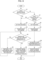
- Fig. 8 is a flowchart of an exemplary control operation performed by the processor 410 (see Fig. 4 ).
- the symbol, S, illustrated in Fig. 8 means a step.
- the processor 410 which has started running a program, determines whether a user has instructed that the non-fixing mode is to be used (step 1).
- the processor 410 transfers an image onto a medium 500 (step 3).
- the processor 410 determines whether the temperature in the fixing unit 200 is greater than or equal to the reference value (step 4).
- the temperature is the ambient temperature in the heating chamber which is measured by the temperature sensor 250 (see Fig. 3 ).
- step 4 When the temperature in the fixing unit 200 is lower than the reference value, a negative result is obtained in step 4.
- the processor 410 transports the medium, onto which the image has been transferred, to the discharge position without stopping the medium in the fixing unit 200 (step 6). In this case, since the temperature in the fixing unit 200 is less than the reference value and the medium 500 passes through the fixing unit 200 without stopping in the fixing unit 200, the image, which has been transferred onto the surface of the medium 500, is not fixed.
- step 7 if a positive result is obtained in step 7, the processor 410 sets the operation mode to the non-fixing mode (step 2). After that, steps 3 to 6 are performed.
- step 7 the processor 410 sets the operation mode to the fixing mode (step 8).
- the processor 410 takes the medium, onto which the image has been transferred, into the fixing unit 200 for heating (step 10). Since it is in the fixing mode, the temperature in the heating chamber is greater than or equal to the reference value. Therefore, the image is fixed onto the surface of the medium 500.
- the processor 410 transports the medium 500, on which the image has been fixed, to the discharge position (step 11).
- Fig. 9 is a diagram for describing a schematic configuration of a fixing unit 200A used in the image forming apparatus 10 assumed in the second exemplary embodiment.
- parts corresponding to those in Fig. 3 are designated with the corresponding reference numerals.
- the laser source 210A In the case of use of the laser source 210A, a local portion of the surface of a medium 500 is heated. Thus, the shutters 220, 230, and 240 are not provided. In addition, the temperature sensor 250 is also unnecessary.
- Fig. 10A is a diagram illustrating the mode M1 for describing the position of the fixing roller 210B in the fixing mode.
- the fixing roller 210B is lowered to the height at which the fixing roller 210B is in contact with the surface of a medium 500 which moves in the horizontal direction.
- Fig. 10B is a diagram illustrating the mode M2 for describing the position of the fixing roller 210B in the non-fixing mode.
- the fixing roller 210B In the non-fixing mode, the fixing roller 210B is raised to a height at which the fixing roller 210B is not in contact with the surface of a medium 500 which moves in the horizontal direction. That is, the fixing roller 210B is evacuated from the transport path.
- processor is broad enough to encompass one processor or plural processors in collaboration which are located physically apart from each other but may work cooperatively.
- the order of operations of the processor is not limited to one described in the embodiments above, and may be changed.
Landscapes
- Physics & Mathematics (AREA)
- General Physics & Mathematics (AREA)
- Engineering & Computer Science (AREA)
- Ceramic Engineering (AREA)
- Textile Engineering (AREA)
- Manufacturing & Machinery (AREA)
- Control Or Security For Electrophotography (AREA)
- Electrostatic Charge, Transfer And Separation In Electrography (AREA)
- Ink Jet (AREA)
- Accessory Devices And Overall Control Thereof (AREA)
- Fixing For Electrophotography (AREA)
Claims (5)
- Bilderzeugungssystem (10), umfassend:einen Transporter (300), der ein Objekt (500) transportiert;eine Übertragungseinheit (100), die ein Bild auf das Objekt (500), das von dem Transporter (300) transportiert wird, überträgt;eine Fixiereinheit (200), die das durch die Übertragungseinheit (100) übertragene Bild auf dem Objekt (500) fixiert; undeinen Prozessor (400), der so konfiguriert ist, dass er:in einem ersten Modus Steuerung ausübt, um das Bild auf das Objekt (500) so zu übertragen, dass das Bild durch die Fixiereinheit (200) auf dem Objekt (500) fixiert wird;in einem zweiten Modus Steuerung ausübt, um das Bild auf das Objekt (500) so zu übertragen, dass das Bild durch die Fixiereinheit (200) auf dem Objekt (500) nicht fixiert wird,gekennzeichnet dadurch, dassder Prozessor (400) ferner so konfiguriert ist, dass er:
wenn eine Anweisung zum Ändern des Objekts (500) so, dass das Bild auf ein anderes Objekt übertragen wird, wobei die Dicke oder die Form geändert wird, durch eine Betätigungseinheit (450) empfangen wird, einen Übergang zu dem zweiten Modus durchführt. - Bilderzeugungssystem (10) nach Anspruch 1,
wobei der Prozessor (400) so konfiguriert ist, dass er:
in dem zweiten Modus, bis eine Temperatur bei der Fixiereinheit niedriger als ein Referenzwert ist, stoppt, das Objekt (500), auf das das Bild übertragen wurde, zu der Fixiereinheit (200) zu bewegen. - Bilderzeugungssystem (10) nach Anspruch 1 oder 2,wobei die Fixiereinheit (200) eine Lichtquelle (210A) umfasst, undwobei der Prozessor (400) so konfiguriert ist, dass er:in dem ersten Modus die Fixiereinheit (200) veranlasst, Emission von Licht zum Fixieren des Bildes auf dem Objekt (500) durchzuführen; undin dem zweiten Modus die Fixiereinheit (200) veranlasst, Emission von Licht zum Fixieren des Bildes auf dem Objekt (500) zu stoppen.
- Bilderzeugungssystem (10) nach einem der Ansprüche 1 bis 3,
wobei der Prozessor (400) so konfiguriert ist, dass er:in dem ersten Modus die Fixiereinheit (200) zu einem Transportweg (310) für das Objekt (500) hin bewegt; undin dem zweiten Modus die Fixiereinheit weg von dem Transportweg (310) für das Objekt (500) bewegt, wobei die Fixiereinheit (200) das übertragene Bild durch Kontakt mit dem Objekt fixiert. - Bilderzeugungsverfahren, umfassend:Transportieren eines Objekts (500);Übertragen eines Bildes auf das transportierte Objekt (500);Fixieren des übertragenen Bildes auf dem Objekt (500);in einem ersten Modus, Ausüben von Steuerung, um das Bild auf das Objekt (500) so zu übertragen, dass das Bild auf dem Objekt (500) fixiert wird;in einem zweiten Modus, Ausüben von Steuerung, um das Bild auf das Objekt (500) so zu übertragen, dass das Bild nicht auf dem Objekt (500) fixiert wird,gekennzeichnet dadurch, dassdas Bilderzeugungsverfahren ferner umfasst:
wenn eine Anweisung zum Ändern des Objekts (500) so, dass das Bild auf ein anderes Objekt übertragen wird, wobei die Dicke oder die Form geändert wird, durch eine Betätigungseinheit (450) empfangen wird, Durchführen eines Übergangs zu dem zweiten Modus.
Applications Claiming Priority (1)
| Application Number | Priority Date | Filing Date | Title |
|---|---|---|---|
| JP2022103399A JP2024003996A (ja) | 2022-06-28 | 2022-06-28 | 画像形成システム |
Publications (2)
| Publication Number | Publication Date |
|---|---|
| EP4300207A1 EP4300207A1 (de) | 2024-01-03 |
| EP4300207B1 true EP4300207B1 (de) | 2025-04-16 |
Family
ID=85724802
Family Applications (1)
| Application Number | Title | Priority Date | Filing Date |
|---|---|---|---|
| EP23163377.7A Active EP4300207B1 (de) | 2022-06-28 | 2023-03-22 | Bilderzeugungssystem und bilderzeugungsverfahren |
Country Status (4)
| Country | Link |
|---|---|
| US (1) | US12085878B2 (de) |
| EP (1) | EP4300207B1 (de) |
| JP (1) | JP2024003996A (de) |
| CN (1) | CN117311111A (de) |
Citations (3)
| Publication number | Priority date | Publication date | Assignee | Title |
|---|---|---|---|---|
| JPS5991471A (ja) * | 1982-11-18 | 1984-05-26 | Ricoh Co Ltd | 電子写真複写機 |
| US6205297B1 (en) * | 1995-10-09 | 2001-03-20 | Canon Kabushiki Kaisha | Recording apparatus with automatic paper discharge and fixing roller temperature control features |
| KR20030026639A (ko) * | 2001-09-26 | 2003-04-03 | 삼성전자주식회사 | 복합 화상형성장치 및 이를 이용한 인쇄방법 |
Family Cites Families (13)
| Publication number | Priority date | Publication date | Assignee | Title |
|---|---|---|---|---|
| JPS63163882A (ja) | 1986-12-26 | 1988-07-07 | Toshiba Corp | 定着装置のシヤツタ装置 |
| JPH0329295A (ja) | 1989-06-24 | 1991-02-07 | Matsushita Electric Works Ltd | 調光装置 |
| JPH05165282A (ja) | 1991-12-12 | 1993-07-02 | Canon Inc | 画像形成装置 |
| WO1998029784A1 (en) | 1996-12-27 | 1998-07-09 | Kao Corporation | Printing method, printer, printed matter, and optical disk |
| US20020021911A1 (en) * | 2000-06-09 | 2002-02-21 | Masahiko Matsuura | Image forming apparatus |
| TWM480093U (zh) * | 2014-02-18 | 2014-06-11 | Avision Inc | 可分離的定影裝置以及應用其之列印設備 |
| US9939760B2 (en) | 2015-12-24 | 2018-04-10 | Canon Kabushiki Kaisha | Image forming apparatus |
| US10137634B2 (en) | 2016-04-28 | 2018-11-27 | Xerox Corporation | Hybrid electrostatic 3-D printer using laser fusing |
| JP6900650B2 (ja) | 2016-10-17 | 2021-07-07 | 富士フイルムビジネスイノベーション株式会社 | 画像形成装置、及び画像形成方法 |
| JP2022032317A (ja) * | 2020-08-11 | 2022-02-25 | キヤノン株式会社 | 画像形成装置 |
| EP3964365B1 (de) | 2020-09-08 | 2026-05-06 | Fujifilm Business Innovation Corp. | Transportvorrichtung, fixiervorrichtung und bilderzeugungsvorrichtung |
| JP2024003990A (ja) * | 2022-06-28 | 2024-01-16 | 富士フイルムビジネスイノベーション株式会社 | 画像形成装置 |
| JP2024003993A (ja) * | 2022-06-28 | 2024-01-16 | 富士フイルムビジネスイノベーション株式会社 | 画像形成装置 |
-
2022
- 2022-06-28 JP JP2022103399A patent/JP2024003996A/ja active Pending
- 2022-11-18 US US17/989,698 patent/US12085878B2/en active Active
-
2023
- 2023-01-04 CN CN202310007242.2A patent/CN117311111A/zh active Pending
- 2023-03-22 EP EP23163377.7A patent/EP4300207B1/de active Active
Patent Citations (3)
| Publication number | Priority date | Publication date | Assignee | Title |
|---|---|---|---|---|
| JPS5991471A (ja) * | 1982-11-18 | 1984-05-26 | Ricoh Co Ltd | 電子写真複写機 |
| US6205297B1 (en) * | 1995-10-09 | 2001-03-20 | Canon Kabushiki Kaisha | Recording apparatus with automatic paper discharge and fixing roller temperature control features |
| KR20030026639A (ko) * | 2001-09-26 | 2003-04-03 | 삼성전자주식회사 | 복합 화상형성장치 및 이를 이용한 인쇄방법 |
Also Published As
| Publication number | Publication date |
|---|---|
| JP2024003996A (ja) | 2024-01-16 |
| US20230418195A1 (en) | 2023-12-28 |
| CN117311111A (zh) | 2023-12-29 |
| EP4300207A1 (de) | 2024-01-03 |
| US12085878B2 (en) | 2024-09-10 |
Similar Documents
| Publication | Publication Date | Title |
|---|---|---|
| US8152159B2 (en) | Sheet feeding device and image forming apparatus including a controlled elevator mechanism | |
| US7792446B2 (en) | Image heating apparatus with controller for changing time duration of pressing belt with fixing member | |
| CN103135417A (zh) | 图像形成装置 | |
| JP2024003990A (ja) | 画像形成装置 | |
| EP4300207B1 (de) | Bilderzeugungssystem und bilderzeugungsverfahren | |
| EP1995645B1 (de) | Bilderzeugungsvorrichtung | |
| US20160124358A1 (en) | Image forming apparatus and image forming method | |
| EP4300204B1 (de) | Bilderzeugungssystem und bilderzeugungsverfahren | |
| JP2024003993A (ja) | 画像形成装置 | |
| US9207634B2 (en) | Image formation apparatus that has temperature sensor for detecting temperature therein | |
| US10739725B2 (en) | Image forming apparatus | |
| JP2020008766A (ja) | 画像形成装置及び定着装置 | |
| US20240329567A1 (en) | Image forming apparatus | |
| EP4300208B1 (de) | Bilderzeugungsgerät | |
| JP5093273B2 (ja) | 定着装置および画像形成装置 | |
| JP2013174800A (ja) | 画像形成装置 | |
| JP2024003989A (ja) | 画像形成装置 | |
| JP7087914B2 (ja) | 画像形成装置 | |
| JP5701086B2 (ja) | 画像形成装置 | |
| JP2006119175A (ja) | 画像形成装置 | |
| JP2024003992A (ja) | 画像形成装置 | |
| JP2005077562A (ja) | 画像形成装置 | |
| JP2006163193A (ja) | 画像形成装置 | |
| JP2015125352A (ja) | 画像形成装置 |
Legal Events
| Date | Code | Title | Description |
|---|---|---|---|
| PUAI | Public reference made under article 153(3) epc to a published international application that has entered the european phase |
Free format text: ORIGINAL CODE: 0009012 |
|
| STAA | Information on the status of an ep patent application or granted ep patent |
Free format text: STATUS: THE APPLICATION HAS BEEN PUBLISHED |
|
| AK | Designated contracting states |
Kind code of ref document: A1 Designated state(s): AL AT BE BG CH CY CZ DE DK EE ES FI FR GB GR HR HU IE IS IT LI LT LU LV MC ME MK MT NL NO PL PT RO RS SE SI SK SM TR |
|
| STAA | Information on the status of an ep patent application or granted ep patent |
Free format text: STATUS: REQUEST FOR EXAMINATION WAS MADE |
|
| 17P | Request for examination filed |
Effective date: 20240531 |
|
| RBV | Designated contracting states (corrected) |
Designated state(s): AL AT BE BG CH CY CZ DE DK EE ES FI FR GB GR HR HU IE IS IT LI LT LU LV MC ME MK MT NL NO PL PT RO RS SE SI SK SM TR |
|
| STAA | Information on the status of an ep patent application or granted ep patent |
Free format text: STATUS: EXAMINATION IS IN PROGRESS |
|
| 17Q | First examination report despatched |
Effective date: 20240723 |
|
| GRAP | Despatch of communication of intention to grant a patent |
Free format text: ORIGINAL CODE: EPIDOSNIGR1 |
|
| STAA | Information on the status of an ep patent application or granted ep patent |
Free format text: STATUS: GRANT OF PATENT IS INTENDED |
|
| INTG | Intention to grant announced |
Effective date: 20250117 |
|
| GRAS | Grant fee paid |
Free format text: ORIGINAL CODE: EPIDOSNIGR3 |
|
| GRAA | (expected) grant |
Free format text: ORIGINAL CODE: 0009210 |
|
| STAA | Information on the status of an ep patent application or granted ep patent |
Free format text: STATUS: THE PATENT HAS BEEN GRANTED |
|
| AK | Designated contracting states |
Kind code of ref document: B1 Designated state(s): AL AT BE BG CH CY CZ DE DK EE ES FI FR GB GR HR HU IE IS IT LI LT LU LV MC ME MK MT NL NO PL PT RO RS SE SI SK SM TR |
|
| REG | Reference to a national code |
Ref country code: GB Ref legal event code: FG4D |
|
| REG | Reference to a national code |
Ref country code: CH Ref legal event code: EP |
|
| REG | Reference to a national code |
Ref country code: IE Ref legal event code: FG4D |
|
| REG | Reference to a national code |
Ref country code: DE Ref legal event code: R096 Ref document number: 602023002884 Country of ref document: DE |
|
| REG | Reference to a national code |
Ref country code: NL Ref legal event code: MP Effective date: 20250416 |
|
| PG25 | Lapsed in a contracting state [announced via postgrant information from national office to epo] |
Ref country code: NL Free format text: LAPSE BECAUSE OF FAILURE TO SUBMIT A TRANSLATION OF THE DESCRIPTION OR TO PAY THE FEE WITHIN THE PRESCRIBED TIME-LIMIT Effective date: 20250416 |
|
| REG | Reference to a national code |
Ref country code: AT Ref legal event code: MK05 Ref document number: 1786141 Country of ref document: AT Kind code of ref document: T Effective date: 20250416 |
|
| PG25 | Lapsed in a contracting state [announced via postgrant information from national office to epo] |
Ref country code: FI Free format text: LAPSE BECAUSE OF FAILURE TO SUBMIT A TRANSLATION OF THE DESCRIPTION OR TO PAY THE FEE WITHIN THE PRESCRIBED TIME-LIMIT Effective date: 20250416 Ref country code: ES Free format text: LAPSE BECAUSE OF FAILURE TO SUBMIT A TRANSLATION OF THE DESCRIPTION OR TO PAY THE FEE WITHIN THE PRESCRIBED TIME-LIMIT Effective date: 20250416 Ref country code: PT Free format text: LAPSE BECAUSE OF FAILURE TO SUBMIT A TRANSLATION OF THE DESCRIPTION OR TO PAY THE FEE WITHIN THE PRESCRIBED TIME-LIMIT Effective date: 20250818 |
|
| REG | Reference to a national code |
Ref country code: LT Ref legal event code: MG9D |
|
| PG25 | Lapsed in a contracting state [announced via postgrant information from national office to epo] |
Ref country code: NO Free format text: LAPSE BECAUSE OF FAILURE TO SUBMIT A TRANSLATION OF THE DESCRIPTION OR TO PAY THE FEE WITHIN THE PRESCRIBED TIME-LIMIT Effective date: 20250716 Ref country code: GR Free format text: LAPSE BECAUSE OF FAILURE TO SUBMIT A TRANSLATION OF THE DESCRIPTION OR TO PAY THE FEE WITHIN THE PRESCRIBED TIME-LIMIT Effective date: 20250717 |
|
| PG25 | Lapsed in a contracting state [announced via postgrant information from national office to epo] |
Ref country code: PL Free format text: LAPSE BECAUSE OF FAILURE TO SUBMIT A TRANSLATION OF THE DESCRIPTION OR TO PAY THE FEE WITHIN THE PRESCRIBED TIME-LIMIT Effective date: 20250416 |
|
| PG25 | Lapsed in a contracting state [announced via postgrant information from national office to epo] |
Ref country code: BG Free format text: LAPSE BECAUSE OF FAILURE TO SUBMIT A TRANSLATION OF THE DESCRIPTION OR TO PAY THE FEE WITHIN THE PRESCRIBED TIME-LIMIT Effective date: 20250416 |
|
| PG25 | Lapsed in a contracting state [announced via postgrant information from national office to epo] |
Ref country code: HR Free format text: LAPSE BECAUSE OF FAILURE TO SUBMIT A TRANSLATION OF THE DESCRIPTION OR TO PAY THE FEE WITHIN THE PRESCRIBED TIME-LIMIT Effective date: 20250416 |
|
| PG25 | Lapsed in a contracting state [announced via postgrant information from national office to epo] |
Ref country code: AT Free format text: LAPSE BECAUSE OF FAILURE TO SUBMIT A TRANSLATION OF THE DESCRIPTION OR TO PAY THE FEE WITHIN THE PRESCRIBED TIME-LIMIT Effective date: 20250416 |
|
| PG25 | Lapsed in a contracting state [announced via postgrant information from national office to epo] |
Ref country code: RS Free format text: LAPSE BECAUSE OF FAILURE TO SUBMIT A TRANSLATION OF THE DESCRIPTION OR TO PAY THE FEE WITHIN THE PRESCRIBED TIME-LIMIT Effective date: 20250716 |
|
| PG25 | Lapsed in a contracting state [announced via postgrant information from national office to epo] |
Ref country code: IS Free format text: LAPSE BECAUSE OF FAILURE TO SUBMIT A TRANSLATION OF THE DESCRIPTION OR TO PAY THE FEE WITHIN THE PRESCRIBED TIME-LIMIT Effective date: 20250816 |
|
| PG25 | Lapsed in a contracting state [announced via postgrant information from national office to epo] |
Ref country code: LV Free format text: LAPSE BECAUSE OF FAILURE TO SUBMIT A TRANSLATION OF THE DESCRIPTION OR TO PAY THE FEE WITHIN THE PRESCRIBED TIME-LIMIT Effective date: 20250416 |
|
| PG25 | Lapsed in a contracting state [announced via postgrant information from national office to epo] |
Ref country code: DK Free format text: LAPSE BECAUSE OF FAILURE TO SUBMIT A TRANSLATION OF THE DESCRIPTION OR TO PAY THE FEE WITHIN THE PRESCRIBED TIME-LIMIT Effective date: 20250416 Ref country code: SM Free format text: LAPSE BECAUSE OF FAILURE TO SUBMIT A TRANSLATION OF THE DESCRIPTION OR TO PAY THE FEE WITHIN THE PRESCRIBED TIME-LIMIT Effective date: 20250416 |
|
| REG | Reference to a national code |
Ref country code: DE Ref legal event code: R097 Ref document number: 602023002884 Country of ref document: DE |
|
| PG25 | Lapsed in a contracting state [announced via postgrant information from national office to epo] |
Ref country code: CZ Free format text: LAPSE BECAUSE OF FAILURE TO SUBMIT A TRANSLATION OF THE DESCRIPTION OR TO PAY THE FEE WITHIN THE PRESCRIBED TIME-LIMIT Effective date: 20250416 |
|
| PG25 | Lapsed in a contracting state [announced via postgrant information from national office to epo] |
Ref country code: EE Free format text: LAPSE BECAUSE OF FAILURE TO SUBMIT A TRANSLATION OF THE DESCRIPTION OR TO PAY THE FEE WITHIN THE PRESCRIBED TIME-LIMIT Effective date: 20250416 |
|
| PG25 | Lapsed in a contracting state [announced via postgrant information from national office to epo] |
Ref country code: SK Free format text: LAPSE BECAUSE OF FAILURE TO SUBMIT A TRANSLATION OF THE DESCRIPTION OR TO PAY THE FEE WITHIN THE PRESCRIBED TIME-LIMIT Effective date: 20250416 |
|
| PG25 | Lapsed in a contracting state [announced via postgrant information from national office to epo] |
Ref country code: IT Free format text: LAPSE BECAUSE OF FAILURE TO SUBMIT A TRANSLATION OF THE DESCRIPTION OR TO PAY THE FEE WITHIN THE PRESCRIBED TIME-LIMIT Effective date: 20250416 |
|
| P01 | Opt-out of the competence of the unified patent court (upc) registered |
Free format text: CASE NUMBER: UPC_APP_0000857_4300207/2026 Effective date: 20260109 |
|
| PLBE | No opposition filed within time limit |
Free format text: ORIGINAL CODE: 0009261 |
|
| STAA | Information on the status of an ep patent application or granted ep patent |
Free format text: STATUS: NO OPPOSITION FILED WITHIN TIME LIMIT |
|
| REG | Reference to a national code |
Ref country code: CH Ref legal event code: L10 Free format text: ST27 STATUS EVENT CODE: U-0-0-L10-L00 (AS PROVIDED BY THE NATIONAL OFFICE) Effective date: 20260225 |
|
| 26N | No opposition filed |
Effective date: 20260119 |
|
| PGFP | Annual fee paid to national office [announced via postgrant information from national office to epo] |
Ref country code: DE Payment date: 20260128 Year of fee payment: 4 |
|
| PGFP | Annual fee paid to national office [announced via postgrant information from national office to epo] |
Ref country code: FR Payment date: 20260209 Year of fee payment: 4 |