EP4300254A1 - Drehwellenmechanismus und endgerätevorrichtung - Google Patents
Drehwellenmechanismus und endgerätevorrichtung Download PDFInfo
- Publication number
- EP4300254A1 EP4300254A1 EP22774154.3A EP22774154A EP4300254A1 EP 4300254 A1 EP4300254 A1 EP 4300254A1 EP 22774154 A EP22774154 A EP 22774154A EP 4300254 A1 EP4300254 A1 EP 4300254A1
- Authority
- EP
- European Patent Office
- Prior art keywords
- rotating
- assembly
- sliding
- main shaft
- rotating shaft
- Prior art date
- Legal status (The legal status is an assumption and is not a legal conclusion. Google has not performed a legal analysis and makes no representation as to the accuracy of the status listed.)
- Pending
Links
Images





Classifications
-
- H—ELECTRICITY
- H04—ELECTRIC COMMUNICATION TECHNIQUE
- H04M—TELEPHONIC COMMUNICATION
- H04M1/00—Substation equipment, e.g. for use by subscribers
- H04M1/02—Constructional features of telephone sets
- H04M1/0202—Portable telephone sets, e.g. cordless phones, mobile phones or bar type handsets
- H04M1/0206—Portable telephones comprising a plurality of mechanically joined movable body parts, e.g. hinged housings
- H04M1/0208—Portable telephones comprising a plurality of mechanically joined movable body parts, e.g. hinged housings characterized by the relative motions of the body parts
- H04M1/0214—Foldable telephones, i.e. with body parts pivoting to an open position around an axis parallel to the plane they define in closed position
- H04M1/0216—Foldable in one direction, i.e. using a one degree of freedom hinge
- H04M1/022—The hinge comprising two parallel pivoting axes
-
- F—MECHANICAL ENGINEERING; LIGHTING; HEATING; WEAPONS; BLASTING
- F16—ENGINEERING ELEMENTS AND UNITS; GENERAL MEASURES FOR PRODUCING AND MAINTAINING EFFECTIVE FUNCTIONING OF MACHINES OR INSTALLATIONS; THERMAL INSULATION IN GENERAL
- F16C—SHAFTS; FLEXIBLE SHAFTS; ELEMENTS OR CRANKSHAFT MECHANISMS; ROTARY BODIES OTHER THAN GEARING ELEMENTS; BEARINGS
- F16C11/00—Pivots; Pivotal connections
- F16C11/04—Pivotal connections
- F16C11/12—Pivotal connections incorporating flexible connections, e.g. leaf springs
-
- F—MECHANICAL ENGINEERING; LIGHTING; HEATING; WEAPONS; BLASTING
- F16—ENGINEERING ELEMENTS AND UNITS; GENERAL MEASURES FOR PRODUCING AND MAINTAINING EFFECTIVE FUNCTIONING OF MACHINES OR INSTALLATIONS; THERMAL INSULATION IN GENERAL
- F16C—SHAFTS; FLEXIBLE SHAFTS; ELEMENTS OR CRANKSHAFT MECHANISMS; ROTARY BODIES OTHER THAN GEARING ELEMENTS; BEARINGS
- F16C11/00—Pivots; Pivotal connections
- F16C11/04—Pivotal connections
-
- G—PHYSICS
- G06—COMPUTING OR CALCULATING; COUNTING
- G06F—ELECTRIC DIGITAL DATA PROCESSING
- G06F1/00—Details not covered by groups G06F3/00 - G06F13/00 and G06F21/00
- G06F1/16—Constructional details or arrangements
- G06F1/1613—Constructional details or arrangements for portable computers
- G06F1/1615—Constructional details or arrangements for portable computers with several enclosures having relative motions, each enclosure supporting at least one I/O or computing function
- G06F1/1616—Constructional details or arrangements for portable computers with several enclosures having relative motions, each enclosure supporting at least one I/O or computing function with folding flat displays, e.g. laptop computers or notebooks having a clamshell configuration, with body parts pivoting to an open position around an axis parallel to the plane they define in closed position
-
- G—PHYSICS
- G06—COMPUTING OR CALCULATING; COUNTING
- G06F—ELECTRIC DIGITAL DATA PROCESSING
- G06F1/00—Details not covered by groups G06F3/00 - G06F13/00 and G06F21/00
- G06F1/16—Constructional details or arrangements
- G06F1/1613—Constructional details or arrangements for portable computers
- G06F1/1633—Constructional details or arrangements of portable computers not specific to the type of enclosures covered by groups G06F1/1615 - G06F1/1626
- G06F1/1637—Details related to the display arrangement, including those related to the mounting of the display in the housing
- G06F1/1641—Details related to the display arrangement, including those related to the mounting of the display in the housing the display being formed by a plurality of foldable display components
-
- G—PHYSICS
- G06—COMPUTING OR CALCULATING; COUNTING
- G06F—ELECTRIC DIGITAL DATA PROCESSING
- G06F1/00—Details not covered by groups G06F3/00 - G06F13/00 and G06F21/00
- G06F1/16—Constructional details or arrangements
- G06F1/1613—Constructional details or arrangements for portable computers
- G06F1/1633—Constructional details or arrangements of portable computers not specific to the type of enclosures covered by groups G06F1/1615 - G06F1/1626
- G06F1/1637—Details related to the display arrangement, including those related to the mounting of the display in the housing
- G06F1/1652—Details related to the display arrangement, including those related to the mounting of the display in the housing the display being flexible, e.g. mimicking a sheet of paper, or rollable
-
- G—PHYSICS
- G06—COMPUTING OR CALCULATING; COUNTING
- G06F—ELECTRIC DIGITAL DATA PROCESSING
- G06F1/00—Details not covered by groups G06F3/00 - G06F13/00 and G06F21/00
- G06F1/16—Constructional details or arrangements
- G06F1/1613—Constructional details or arrangements for portable computers
- G06F1/1633—Constructional details or arrangements of portable computers not specific to the type of enclosures covered by groups G06F1/1615 - G06F1/1626
- G06F1/1675—Miscellaneous details related to the relative movement between the different enclosures or enclosure parts
- G06F1/1681—Details related solely to hinges
-
- G—PHYSICS
- G09—EDUCATION; CRYPTOGRAPHY; DISPLAY; ADVERTISING; SEALS
- G09F—DISPLAYING; ADVERTISING; SIGNS; LABELS OR NAME-PLATES; SEALS
- G09F9/00—Indicating arrangements for variable information in which the information is built-up on a support by selection or combination of individual elements
- G09F9/30—Indicating arrangements for variable information in which the information is built-up on a support by selection or combination of individual elements in which the desired character or characters are formed by combining individual elements
- G09F9/301—Indicating arrangements for variable information in which the information is built-up on a support by selection or combination of individual elements in which the desired character or characters are formed by combining individual elements flexible foldable or roll-able electronic displays, e.g. thin LCD, OLED
-
- H—ELECTRICITY
- H05—ELECTRIC TECHNIQUES NOT OTHERWISE PROVIDED FOR
- H05K—PRINTED CIRCUITS; CASINGS OR CONSTRUCTIONAL DETAILS OF ELECTRIC APPARATUS; MANUFACTURE OF ASSEMBLAGES OF ELECTRICAL COMPONENTS
- H05K5/00—Casings, cabinets or drawers for electric apparatus
- H05K5/02—Details
- H05K5/0217—Mechanical details of casings
- H05K5/0226—Hinges
-
- E—FIXED CONSTRUCTIONS
- E05—LOCKS; KEYS; WINDOW OR DOOR FITTINGS; SAFES
- E05D—HINGES OR SUSPENSION DEVICES FOR DOORS, WINDOWS OR WINGS
- E05D3/00—Hinges with pins
- E05D3/06—Hinges with pins with two or more pins
- E05D3/12—Hinges with pins with two or more pins with two parallel pins and one arm
-
- E—FIXED CONSTRUCTIONS
- E05—LOCKS; KEYS; WINDOW OR DOOR FITTINGS; SAFES
- E05Y—INDEXING SCHEME ASSOCIATED WITH SUBCLASSES E05D AND E05F, RELATING TO CONSTRUCTION ELEMENTS, ELECTRIC CONTROL, POWER SUPPLY, POWER SIGNAL OR TRANSMISSION, USER INTERFACES, MOUNTING OR COUPLING, DETAILS, ACCESSORIES, AUXILIARY OPERATIONS NOT OTHERWISE PROVIDED FOR, APPLICATION THEREOF
- E05Y2999/00—Subject-matter not otherwise provided for in this subclass
-
- H—ELECTRICITY
- H04—ELECTRIC COMMUNICATION TECHNIQUE
- H04M—TELEPHONIC COMMUNICATION
- H04M1/00—Substation equipment, e.g. for use by subscribers
- H04M1/02—Constructional features of telephone sets
- H04M1/0202—Portable telephone sets, e.g. cordless phones, mobile phones or bar type handsets
- H04M1/026—Details of the structure or mounting of specific components
- H04M1/0266—Details of the structure or mounting of specific components for a display module assembly
- H04M1/0268—Details of the structure or mounting of specific components for a display module assembly including a flexible display panel
Definitions
- This application relates to the field of terminal device technologies, and in particular, to a rotating shaft mechanism and a terminal device.
- the foldable terminal product (for example, an electronic device such as a foldable mobile phone, a foldable tablet computer, or a foldable computer) needs to have high reliability and good operation experience, so that the foldable terminal product can be easily accepted by a consumer.
- the foldable mobile phone is used as an example.
- a flexible display of the foldable mobile phone may flexibly change based on different application scenarios, to switch a use mode. This is also a current research and development direction of a mobile phone manufacturer.
- the flexible display is only a part of a structure of the foldable mobile phone.
- a rotating shaft mechanism also needs to cooperate, so that an entire terminal product is foldable.
- the rotating shaft mechanism may provide enough damping forces for the entire foldable mobile phone in different folding states, so that the foldable mobile phone has reliable support in a folding state switching process.
- the foldable terminal product has reliable support, to effectively reduce a risk of damage to the flexible display. Therefore, a magnitude and stability of an effective damping force that can be provided by the rotating shaft mechanism for the entire terminal product have become a research focus of a person skilled in the art.
- This application provides a rotating shaft mechanism and a terminal device, so that the rotating shaft mechanism can provide, for the entire terminal device, a damping force that meets a requirement.
- a rotating shaft mechanism may be applied to a foldable terminal device, the terminal device includes two housings, and the two housings may separately rotate around the rotating shaft mechanism, to fold and unfold the terminal device.
- the rotating shaft mechanism includes a main shaft assembly and a damper assembly, and the damper assembly is rotatably connected to the main shaft assembly.
- the damper assembly may include a cam member and a rotating assembly, the cam member is fastened on the main shaft assembly, and the cam member has a cam surface.
- the rotating assembly includes a rotating member and a sliding member, and the rotating member is rotatably connected to the main shaft assembly, to drive the entire rotating assembly to rotate around the main shaft assembly.
- the sliding member is able to slide in a direction toward or away from the main shaft assembly relative to the rotating member, and the sliding member further elastically abuts against the cam surface in a process in which the sliding member slides relative to the rotating member, to generate a damping force between the main shaft assembly and the damper assembly.
- An abutting force formed through elastic abutting may be transformed into resistance of relative rotation of the cam member and the rotating assembly, to generate the damping force between the main shaft assembly and the damper assembly.
- the elastic abutting force between the sliding member and the cam surface and a specific form of the cam surface are properly designed, to effectively improve a comfort degree of folding operation experience of the terminal device, and further ensure a life of the damper assembly.
- the rotating member is a key structure for rotation of the rotating assembly around the main shaft assembly.
- the rotating member may include a body portion and a connecting portion.
- the connecting portion is fixedly connected to the body portion, the connecting portion is configured to be rotatably connected to the main shaft assembly, the connecting portion may be disposed as an arc shaft, the main shaft assembly is correspondingly provided with an arc groove, and the arc shaft and the arc groove slidably cooperate, so that the rotating member and the main shaft assembly are rotatably connected by using a virtual shaft.
- Such a connection manner may facilitate a thin design of the rotating shaft mechanism.
- the body portion is provided with a sliding groove, and at least a part of the sliding member is accommodated in the sliding groove, so that at least the part of the sliding member can be accommodated in the sliding groove and slide in the sliding groove.
- the rotating member may further include a first rotating arm, a second rotating arm, and a connecting arm.
- the first rotating arm and the second rotating arm each are rotatably connected to the main shaft assembly, and an end portion of the first rotating arm and an end portion of the second rotating arm that face away from the main shaft assembly are fixedly connected by using the connecting arm.
- a part of the first rotating arm, a part of the second rotating arm, and a part of the connecting arm that are configured to enclose the sliding groove may be used as the body portion of the rotating member, and an end portion of the first rotating arm and an end portion of the second rotating arm that are configured to be rotatably connected to the main shaft assembly may be used as the connecting portion of the rotating member.
- the rotating shaft mechanism may include two damper assemblies disposed in pairs, and the two damper assemblies synchronously rotate, to improve motion stability of the rotating shaft mechanism.
- the end portion that is of the first rotating arm and that is configured to be rotatably connected to the main shaft assembly may be provided with a gear structure
- the end portion that is of the second rotating arm and that is configured to be rotatably connected to the main shaft assembly is provided with a gear structure, so that the two damper assemblies synchronously rotate.
- a gear structure of a first rotating arm of one of the two damper assemblies disposed in pairs engages with a gear structure of a first rotating arm or a second rotating arm on a corresponding side of the other damper assembly.
- a gear structure of a second rotating arm of one of the two damper assemblies disposed in pairs engages with a gear structure of a second rotating arm or a first rotating arm on a corresponding side of the other damper assembly.
- gear structures of rotating arms on a corresponding side engage with each other, so that the two damper assemblies synchronously move.
- a baffle plate is disposed on each of two sides of the two gear structures that engage with each other, and the baffle plate is configured to limit a center distance between the two gear structures, to improve stability of motion and transmission of the two gear structures.
- the sliding member in specific disposing of the sliding member, may include a sliding block, and the sliding block may slide in the sliding groove in a direction toward or away from the main shaft assembly.
- a first sliding portion and a second sliding portion may be respectively disposed on two opposite groove walls of the sliding groove, and the sliding block is provided with a third sliding portion and a fourth sliding portion, to improve sliding stability of the sliding block in the sliding groove.
- the third sliding portion slidably cooperates with the first sliding portion
- the fourth sliding portion slidably cooperates with the second sliding portion.
- an elastic element is further disposed in the sliding groove, and the sliding block is elastically connected to the elastic element. Because the cam member may be fastened on the main shaft assembly, in a process in which the sliding block slides in a direction toward or away from the main shaft assembly relative to the rotating member, the elastic element may press the sliding block toward the cam member, so that the sliding block elastically abuts against the cam member.
- the sliding block may be further provided with a roller, the roller is rotatably connected to the sliding block by using a roller shaft, and the roller may elastically abut against the cam surface, so that friction between the sliding member and the cam member is rolling friction, to reduce abrasion caused in a process in which the sliding block moves along the cam surface.
- an end portion of the sliding block may be further provided with an abutting portion, and the abutting portion abuts against the cam surface.
- a surface of the abutting portion may be an arc surface or a spherical surface, to also reduce abrasion between the sliding block and the cam surface.
- a rotating shaft mechanism is further provided.
- the rotating shaft mechanism includes a main shaft assembly and a damper assembly, and the damper assembly is rotatably connected to the main shaft assembly.
- the damper assembly may include a cam member and a rotating assembly, the cam member is disposed on the rotating assembly, and the cam member has a cam surface.
- the rotating assembly includes a rotating member and a sliding member, and the rotating member is rotatably connected to the main shaft assembly, to drive the entire rotating assembly to rotate around the main shaft assembly.
- the sliding member may slide in a direction toward or away from the main shaft assembly relative to the rotating member, and the sliding member further elastically abuts against the cam surface in a process in which the sliding member rotates relative to the rotating member, to generate a damping force between the main shaft assembly and the damper assembly.
- An abutting force formed through elastic abutting may be transformed into resistance of relative rotation of the cam member and the rotating assembly, to generate the damping force between the main shaft assembly and the damper assembly.
- the elastic abutting force between the sliding member and the cam surface and a specific form of the cam surface are properly designed, to effectively improve a comfort degree of folding operation experience of the terminal device, and further ensure a life of the damper assembly.
- the rotating member in specific disposing of the rotating member, includes a body portion and a connecting portion.
- the connecting portion is fixedly connected to the body portion, the connecting portion is configured to be rotatably connected to the main shaft assembly, the connecting portion may be disposed as an arc shaft, the main shaft assembly is correspondingly provided with an arc groove, and the arc shaft and the arc groove slidably cooperate, so that the rotating member and the main shaft assembly are rotatably connected by using a virtual shaft.
- a connection manner may facilitate a thin design of the rotating shaft mechanism.
- the body portion is provided with a sliding groove, and at least a part of the sliding member is accommodated in the sliding groove, so that at least the part of the sliding member can be accommodated in the sliding groove and slide in the sliding groove.
- the sliding member may include a sliding block and a rotating portion, the rotating portion is rotatably connected to the main shaft assembly, and the sliding block is rotatably connected to the rotating portion.
- an axis around which the rotating portion rotates around the main shaft assembly is parallel to but does not overlap an axis around which the rotating member rotates around the main shaft assembly. Therefore, in a process in which the rotating assembly rotates around the main shaft assembly, there is a phase difference between motion of the sliding block and motion of the rotating member, so that the sliding block slides in the sliding groove in a direction toward or away from the main shaft assembly.
- the rotating portion may be provided with a gear structure
- the rotating shaft mechanism may include two damper assemblies disposed in pairs, and gear structures of rotating portions of the two damper assemblies engage with each other, so that the two damper assemblies synchronously rotate, to improve motion stability of the rotating shaft mechanism.
- a baffle plate is disposed on each of two sides of the two gear structures that engage with each other, and the baffle plate is configured to limit a center distance between the two gear structures, to improve stability of motion and transmission of the two gear structures.
- the body portion of the rotating member is further provided with a mounting groove, to dispose the cam member on the rotating assembly.
- an elastic element is disposed in the mounting groove, and the cam member is elastically connected to the elastic element.
- the elastic element may press the cam member toward the sliding block, so that the sliding block elastically abuts against the cam surface of the cam member.
- an end portion that is of the sliding block and that faces the cam member may be further provided with an inclined surface.
- the cam surface of the cam member may abut against the inclined surface, to apply, to the sliding block, a pushing force in a direction away from the main shaft assembly. It can be understood that, the cam surface of the cam member and the inclined surface of the sliding block are properly designed, to adjust a damping force provided by the damper assembly, thereby meeting a requirement of a user for an operation feel.
- the cam member may be further provided with a boss, and the sliding block limits motion of the boss toward a groove opening of the mounting groove, to limit the cam member in the mounting groove. In this way, the cam member can be prevented from falling off from the mounting groove, and structural stability of the rotating shaft mechanism can be improved.
- the main shaft assembly in specific disposing of the main shaft assembly, may include a main inner shaft and a main outer shaft.
- the main inner shaft and the main outer shaft are fastened together to enclose accommodation space for accommodating another component of the rotating shaft mechanism. It can be understood that, a part that is of the rotating assembly and that is configured to be rotatably connected to the main shaft assembly may also be accommodated in the accommodation space.
- a terminal device includes a flexible display, a first housing, a second housing, and the rotating shaft mechanism according to the first aspect or the second aspect.
- the first housing and the second housing are respectively disposed on two sides of the rotating shaft mechanism, and the first housing and the second housing each are connected to a damper assembly on a corresponding side.
- the flexible display may continuously cover the first housing, the second housing, and the rotating shaft mechanism, and the flexible display is fixedly connected to the first housing and the second housing.
- a sliding member elastically abuts against a cam member, to generate a damping force between a main shaft assembly and a damper assembly.
- a specific form of a cam surface of the cam member may be properly designed, to improve a comfort degree of experience of performing a folding operation on the terminal device by using the rotating shaft mechanism, and further ensure a life of the damper assembly.
- the rotating shaft mechanism may be applied to a terminal device, and in particular, is applied to a foldable terminal device.
- the terminal device may be but is not limited to a mobile phone, a personal digital assistant (personal digital assistant, PDA), a notebook computer, or a tablet computer.
- FIG. 1 shows a structure of a foldable terminal device according to a possible embodiment of this application.
- the foldable terminal device may usually include a rotating shaft mechanism 10, a first housing 20, a second housing 30, and a flexible display 40.
- the first housing 20 and the second housing 30 are respectively disposed on two sides of the rotating shaft mechanism 10.
- the flexible display 40 covers the first housing 20, the second housing 30, and the rotating shaft mechanism 10, and may be stuck to the first housing 20, the second housing 30, and the rotating shaft mechanism 10.
- FIG. 2 shows a structure of a terminal device in an unfolded state.
- the first housing 20 and the second housing 30 are respectively disposed on two sides of the rotating shaft mechanism 10.
- a surface of the first housing 20, a surface of the second housing 30, and a surface of the rotating shaft mechanism 10 that are configured to be in contact with the flexible display 40 are approximately in a same plane. Because the flexible display 40 is stuck to the first housing 20, the second housing 30, and the rotating shaft mechanism 10, the flexible display 40 may also be in an unfolded state under a support action of the first housing 20, the second housing 30, and the rotating shaft mechanism 10.
- the terminal device may be an outwardly foldable terminal device, or may be an inwardly foldable terminal device.
- the flexible display 40 is always located on an outer side of the terminal device.
- the flexible display 40 is always located on an inner side of the terminal device.
- the outwardly foldable terminal device is used as an example.
- the first housing 20 and the second housing 30 may rotate relative to each other in a direction shown by a curve with arrows in FIG. 2 , and the flexible display 40 is bent along with the first housing 20 and the second housing 30.
- the flexible display 40 is a key component of the foldable terminal device, in a process in which the foldable terminal device switches a folding mode between the unfolded state, the folded state, and the intermediate state, if the first housing 20, the second housing 30, and the rotating shaft mechanism 10 of the foldable terminal device cannot provide stable support for the flexible display 40, the flexible display 40 may have an abnormal display when being pulled or pressed by an external force. It can be understood, from the descriptions of the terminal device in the foregoing embodiment, that folding of the entire terminal device needs to depend on cooperation of the rotating shaft mechanism 10. Based on this, a damper assembly may be usually disposed in the rotating shaft mechanism 10, so that in the process in which the terminal device switches the folding mode, the damper assembly can provide a reliable damping force for the entire terminal device, to stably support the flexible display 40.
- the damping force provided by the damper assembly is usually implemented based on friction generated by relative motion between components in contact.
- large friction is generated between the components in contact, to provide a damping force that meets a requirement. Long-time use of the components may easily cause wear, and consequently, the damping force of the damper assembly may be reduced.
- the rotating shaft mechanism provided in this application aims to resolve the foregoing problem, to reduce a degree to which the damping force of the damper assembly of the rotating shaft mechanism is reduced, and prolong a service life of the damper assembly, so as to provide effective support for the terminal device to which the rotating shaft mechanism is applied.
- FIG. 3 is a schematic diagram of a structure of a damper assembly according to an embodiment of this application.
- the damper assembly includes two parts that may rotate relative to each other, and the two parts are a cam member 1011 and a rotating assembly 1012.
- the cam member 1011 is a member having a curved contour.
- a surface that is of the cam member 1011 and that includes the curved contour is referred to as a cam surface 10111 of the cam member 1011.
- the rotating assembly 1012 is provided with a guide rail, and is further provided with a sliding block 101221 that may slide along the guide rail. In a process in which the rotating assembly 1012 performs relative rotation, the sliding block 101221 may slide along the guide rail in a direction toward or away from a rotation center of the rotating assembly 1012.
- the damper assembly 101 may be further provided with an elastic element 101224.
- the sliding block 101221 directly or indirectly abuts against the cam surface 10111 of the cam member 1011 under an action of the elastic element 101224 (for example, a spring); or the cam member 1011 abuts against the sliding block 101221 under an action of the elastic element 101224, so that the sliding block 101221 and the cam surface 10111 elastically abut against each other.
- the sliding block 101221 may slide along the guide rail under a pushing action of the cam surface 10111, to compress or stretch the elastic element 101224 to different degrees.
- the elastic element 101224 is compressed or stretched to different degrees, different elastic forces are accumulated by the elastic element 101224, so that the cam member 1011 and the rotating assembly 1012 are subject to different resistance in a relative rotation process. In this way, a variable damping effect between the cam member 1011 and the rotating assembly 1012 that rotate relative to each other can be achieved. It can be understood that a specific form of the cam surface 10111 has great impact on a degree to which the elastic element 101224 is compressed or stretched. Therefore, the damping force provided by the damper assembly 101 can be adjusted by adjusting the specific form of the cam surface 10111.
- the damper assembly 101 of the rotating shaft mechanism 10 provided in this application may be designed based on such a structural principle. To facilitate understanding of the rotating shaft mechanism 10 provided in this embodiment of this application, the following describes a structure of the rotating shaft mechanism 10 in detail with reference to the accompanying drawings.
- FIG. 4a is a schematic diagram of a structure of a rotating shaft mechanism 10 according to a possible embodiment of this application.
- FIG. 4b is a schematic diagram of a structure existing when the rotating shaft mechanism 10 in FIG. 4a is viewed from another perspective.
- the rotating shaft mechanism 10 may include a damper assembly 101 and a main shaft assembly 102.
- the main shaft assembly 102 may be used as a bearing component of the rotating shaft mechanism 10, to be configured to bear the damper assembly 101.
- the damper assembly 101 may be rotatably connected to the main shaft assembly 102.
- an axis direction of a rotating shaft around which the damper assembly 101 rotates may be defined as a length direction of the main shaft assembly 102.
- FIG. 4a and FIG. 4b there may be a plurality of damper assemblies 101, and the plurality of damper assemblies 101 are separately disposed on two sides that are of the main shaft assembly 102 and that are perpendicular to the length direction of the main shaft assembly 102.
- a damper assembly 101 on one side of the main shaft assembly 102 may be fixedly connected to the first housing 20 of the terminal device mentioned in the embodiment shown in FIG. 1 .
- a damper assembly 101 on the other side of the main shaft assembly 102 is fixedly connected to the second housing 30 of the terminal device mentioned in the embodiment shown in FIG.
- damper assemblies 101 disposed on a same side may be directly in contact with and fastened to a housing, or the damper assembly 101 may be fastened to a housing by using another possible structure, to indirectly fasten the damper assembly 101 to the housing.
- damper assemblies 101 there may be a same quantity of damper assemblies 101 located on each of the two sides of the main shaft assembly 102.
- the damper assemblies 101 can provide almost a same damping force for two housings of the terminal device, to help improve structural stability of the terminal device.
- damper assemblies 101 on the two sides of the main shaft assembly 102 may be disposed in a one-to-one correspondence or disposed in a staggered manner. This is not specifically limited in this application.
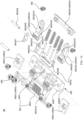
- FIG. 5 is a schematic diagram of an exploded structure of a rotating shaft mechanism 10 according to an embodiment of this application.
- the damper assembly 101 may include a cam member 1011 and a rotating assembly 1012.
- the cam member 1011 may be fastened on the main shaft assembly 102, and the cam member 1011 has a cam surface 10111.
- the rotating assembly 1012 includes a rotating member 10121 and a sliding member 10122, and the rotating member 10121 may rotate around the main shaft assembly 102, to drive the rotating assembly 1012 to rotate around the main shaft assembly 102.
- FIG. 6 shows a structure of a rotating member 10121 according to an embodiment of this application.
- the rotating member 10121 may include a body portion 101211 and a connecting portion 101212, the connecting portion 101212 is disposed on one side of the body portion 101211, and the connecting portion 101212 is fixedly connected to the body portion 101211.
- the rotating member may be of an integral structure, so that structural reliability of the rotating member 10121 can be effectively improved, to improve motion stability of the rotating member 10121.
- the rotating member 10121 may alternatively be of a split structure, and the body portion 101211 and the connecting portion 101212 may be fixedly connected by using a fastener 103 such as a bolt, so that a structure of the rotating member 10121 can be flexibly set.
- the connecting portion 101212 may be configured to be rotatably connected to the main shaft assembly 102.
- the connecting portion 101212 may be disposed as an arc shaft.
- the main shaft assembly 102 is provided with an arc groove 10221, and the arc groove 10221 and the arc shaft are disposed in a one-to-one correspondence.
- each arc shaft may be accommodated in a corresponding arc groove 10221, and an arc surface of the arc shaft may slide along a groove wall of the arc groove 10221, to implement relative rotation of the connecting portion 101212 and the main shaft assembly 102.
- the arc shaft and the arc groove 10221 slidably cooperate, to form a virtual shaft, so that the rotating member 10121 and the main shaft assembly 102 are rotatably connected by using the virtual shaft.
- a structure for rotatably connecting the rotating member 10121 and the main shaft assembly 102 can occupy small space of the main shaft assembly 102, to help implement miniaturization and a thin design of the rotating shaft mechanism 10.
- the rotating member 10121 and the main shaft assembly 102 may alternatively be rotatably connected by using a solid shaft, to effectively simplify the structure of the rotating shaft mechanism 10, and reduce management and control difficulty of a manufacturing process of the rotating shaft mechanism 10.
- the body portion 101211 of the rotating member 10121 is provided with a sliding groove 1012111, at least a part of the sliding member 10122 is accommodated in the sliding groove 1012111, and the sliding member 10122 may slide in the sliding groove 1012111 in a direction (a direction shown by an arrow in FIG. 6 ) toward or away from the main shaft assembly 102.
- one end of the sliding member 10122 may abut against the cam surface 10111 of the cam member 1011. It can be understood that an abutting force between the sliding member 10122 and the cam member 1011 may be transformed into a damping force of the damper assembly 101 and output to an outside.
- the sliding member 10122 includes a sliding block 101221, and the sliding block 101221 is accommodated in the sliding groove 1012111 of the body portion 101211 of the rotating member 10121 and may slide in the sliding groove 1012111 in a direction toward or away from a rotation center of the rotating member 10121 relative to the body portion 101211 of the rotating member 10121.
- a specific shape of the sliding block 101221 is not limited.
- the sliding block 101221 may be of a regular shape such as a rectangle or a trapezoid, or may be of an irregular shape.
- the sliding member 10122 may be further provided with a roller 101222, the roller 101222 may be rotatably connected to an end portion of the sliding block 101221 by using a roller shaft 101223, and the roller 101222 may abut against the cam member 1011, so that a friction pair between the sliding member 10122 and the cam member 1011 is a rolling friction pair, to reduce wear of the sliding member 10122.
- a friction pair between the sliding member 10122 and the cam member 1011 is a rolling friction pair, to reduce wear of the sliding member 10122.
- One end portion of the sliding block 101221 is provided with a mounting hole 1012211, and two end portions of the roller shaft 101223 each are mounted in one mounting hole 1012211.
- the roller shaft 101223 may be fixedly connected to the sliding block 101221 after being mounted in the mounting hole 1012211, and the roller 101222 may rotate around the roller shaft 101223, so that the roller 101222 and the sliding block 101221 are rotatably connected.
- the roller 101222 may be further fixedly connected to the roller shaft 101223, and the roller shaft 101223 may rotate in the mounting hole 1012211 after being mounted in the mounting hole 1012211, so that the roller 101222 and the sliding block 101221 are rotatably connected.
- the roller 101222 is located on a side that is of the sliding block 101221 and that faces the main shaft assembly 102.
- the roller 101222 also slides in the sliding groove 1012111 along with the sliding block 101221 when abutting against the cam surface 10111 of the cam member 1011. Still refer to FIG. 5 .
- an avoidance opening 1012112 is further disposed on a side that is of the sliding groove 1012111 of the rotating member 10121 and that faces the main shaft assembly 102, and the roller 101222 may extend from the avoidance opening 1012112 to an outside of the sliding groove 1012111, to contact the cam member 1011.
- the sliding block 101221 may be further connected to an elastic element 101224, to implement reciprocal motion of the sliding member 10122 in the sliding groove 1012111 in a direction toward and away from the main shaft assembly 102.
- the elastic element 101224 may be but is not limited to a spring or an elastomer.
- the elastic element 101224 may be accommodated in the sliding groove 1012111, the elastic element 101224 is disposed on a side that is of the sliding block 101221 and that faces away from the main shaft assembly 102, one end of the elastic element 101224 is elastically connected to the sliding block 101221, and the other end is elastically connected to a groove wall of the sliding groove 1012111, to press the sliding block 101221 toward the cam member 1011.
- a specific quantity of elastic elements may be set based on a magnitude of a damping force that needs to be provided by the damper assembly 101, space of the sliding groove 1012111, and the like.
- a guide rod 1012212 may be further disposed on a side that is of the sliding block 101221 and that faces away from the main shaft assembly 102. In this way, the elastic element 101224 can be sleeved on the guide rod 1012212, to facilitate mounting of the elastic element 101224 and the sliding block 101221, and further avoid a problem that arching, or the like occurs when the elastic element 101224 is elastically deformed. Therefore, reliability of sliding the sliding block 101221 in the sliding groove 1012111 is improved.
- a hollow region 1012213 may be further disposed on a side that is of the sliding block 101221 and that faces away from the main shaft assembly 102, and the guide rod 1012212 in the foregoing embodiment may be disposed in the hollow region 1012213.
- a structure of the sliding member 10122 can be compact, so that a volume of the rotating assembly 1012 can be small, to help implement a miniaturization design of the rotating shaft mechanism 10.
- at least a part that is of the elastic element 101224 and that is sleeved on the guide rod 1012212 may also be accommodated in the hollow region 1012213, to help limit the elastic element 101224, and improve motion stability of the elastic element 101224.
- the sliding block 101221 may be of an integral structure.
- the hollow region 1012213 may be a groove disposed on the sliding block 101221.
- the sliding block 101221 may alternatively be of a split structure.
- the hollow region 1012213 may be a region enclosed by fixedly connecting a plurality of stoppers that form the sliding block 101221.
- the elastic element 101224 may be a compression spring, and may be compressed and accumulate an elastic acting force in a process in which the sliding block 101221 slides along the sliding groove 1012111.
- the elastic acting force acts on the sliding block 101221, to press the sliding block 101221 toward the cam member 1011, so that the sliding block 101221 abuts against the cam member 1011.
- the rotating assembly 1012 may further include a cover 10123, and the cover 10123 covers an opening of the sliding groove 1012111.
- the cover 10123 and the rotating member 10121 may be threaded by using a fastener 103 such as a screw or a bolt, may be snap-fitted by using a snap-fit, or the like, or may be fixedly connected through sticking by using an adhesive, or the like.
- a fastener 103 such as a screw or a bolt
- a sliding groove cavity may be formed between the cover 10123 and the rotating member 10121. At least the part of the sliding member 10122 mentioned in the foregoing embodiment may be accommodated in the sliding groove cavity, to prevent the sliding member 10122 from falling off from the rotating member 10121.
- FIG. 7 is an exploded diagram of a main shaft assembly 102 according to an embodiment of this application.
- the main shaft assembly 102 may include a main outer shaft 1021 and a main inner shaft 1022, and the main outer shaft 1021 may be but is not limited to an integral plane structure.
- the main inner shaft 1022 and the main outer shaft 1021 are fastened together, and accommodation space for accommodating another component of the rotating shaft mechanism 10 may be enclosed between the main inner shaft 1022 and the main outer shaft 1021.
- the main outer shaft 1021 and the main inner shaft 1022 may be connected by using a fastener 103 such as a bolt or a screw, or may be fixedly connected by using a snap-fit. This constitutes no limitation.
- FIG. 8 is a schematic diagram of a structure of a main inner shaft 1022 according to a possible embodiment of this application.
- the main inner shaft 1022 has a first surface 10222 configured to support the flexible display 40.
- the first surface 10222 may be an arc surface. In this way, when the flexible display 40 shown in FIG. 1 is folded along with the rotating shaft mechanism, the first surface 10222 may be configured to support the flexible display 40.
- a radian of the first surface 10222 may be designed based on a bending radian of a bending part of the flexible display 40, to reduce a risk that the flexible display 40 is damaged when being pressed or pulled.
- FIG. 9 is a sectional view along A-A of the main inner shaft 1022 in FIG. 8 .
- the cam member 1011 of the rotating assembly 1012 mentioned in the foregoing embodiment may be fastened on the main inner shaft 1022.
- the cam member 1011 and the main inner shaft 1022 may alternatively be of an integral structure, to simplify the structure of the rotating shaft mechanism 10, and improve the structural stability of the rotating shaft mechanism 10.
- FIG. 10 is a schematic diagram of a partial structure of a rotating shaft mechanism 10 in an unfolded state.
- the sliding member 10122 elastically abuts against the cam surface 10111 of the cam member 1011 under an elastic force of the elastic element 101224.
- An abutting force formed through elastic abutting may be transformed into resistance of relative rotation of the cam member 1011 and the rotating assembly 1012, to generate the damping force between the main shaft assembly 102 and the damper assembly 101.
- the rotating shaft mechanism 10 can be maintained in the unfolded state, to provide enough support for the terminal device.
- FIG. 11a is a sectional view of a rotating shaft mechanism 10 in an unfolded state.
- FIG. 11b to FIG. 11d each are a sectional view of a rotating shaft mechanism 10 in an intermediate state at a different folding degree. It can be understood that FIG. 11a to FIG. 11d each show only a structure on one side of the rotating shaft mechanism 10, and a structure on the other side of the rotating shaft mechanism 10 is similar to the structure. Therefore, in this embodiment of this application, the structure on one side of the rotating shaft mechanism 10 shown in FIG. 11a to FIG. 11d is only used as an example for description.
- FIG. 12 is a schematic diagram of an operating force in a process in which a rotating shaft mechanism 10 is switched from an unfolded state to a folded state according to an embodiment of this application. It can be understood that, in FIG. 12 , a horizontal coordinate represents a process of switching from an unfolded state to a folded state, and a vertical coordinate represents a magnitude of the operating force.
- the rotating shaft mechanism 10 needs to provide a large damping force to maintain flatness of the entire device.
- the rotating member 10121 rotates around the main shaft assembly 102, and the sliding member 10122 moves along the cam surface 10111 of the cam member 1011 and compresses the elastic element 101224 under an action of the cam member 1011.
- the elastic force of the elastic element 101224 and the specific form of the cam surface 10111 are properly designed, to effectively improve a comfort degree of folding operation experience of the terminal device, and further ensure a life of the damper assembly.
- FIG. 13a is a schematic diagram of a structure of a rotating shaft mechanism 10 according to another embodiment of this application.
- FIG. 13b is a schematic diagram of a structure existing when the rotating shaft mechanism 10 in FIG. 13a is viewed from another perspective.
- a difference between the rotating shaft mechanism 10 in this embodiment and the rotating shaft mechanism 10 provided in the foregoing embodiment mainly lies in a specific disposing manner of a damper assembly 101.
- FIG. 14 is an exploded diagram of a rotating shaft mechanism 10 according to another embodiment of this application.
- the damper assembly 101 may further include a cam member 1011 and a rotating assembly 1012.
- the cam member 1011 is fastened on a main shaft assembly 102 of the rotating shaft mechanism 10, and the cam member 1011 has a cam surface 10111.
- the rotating assembly 1012 includes a rotating member 10121 and a sliding member 10122, and the rotating member 10121 may rotate around the main shaft assembly 102, to drive the entire rotating assembly 1012 to rotate around the main shaft assembly 102.
- the rotating member 10121 includes a first rotating arm 101213, a second rotating arm 101214, and a connecting arm 101215.
- the first rotating arm 101213 and the second rotating arm 101214 are disposed opposite to each other, and each are rotatably connected to the main shaft assembly 102.
- a structure of the first rotating arm 101213 and a structure of the second rotating arm 101214 may be the same.
- an end portion that is of the first rotating arm 101213 and that faces away from the main shaft assembly 102 is fixedly connected to an end portion that is of the second rotating arm 101214 and that faces away from the main shaft assembly 102 by using the connecting arm 101215, so that the rotating member 10121 forms an integral frame structure.
- the first rotating arm 101213 and the second rotating arm 101214 may be fixedly connected to the connecting arm 101215 by using a fastener 103 such as a screw or a bolt. This constitutes no limitation.
- the first rotating arm 101213 and the second rotating arm 101214 may enclose a sliding groove 1012111.
- a part configured to enclose the sliding groove 1012111 may be used as a body portion of the rotating member 10121, and an end portion of the first rotating arm 101213 and an end portion of the second rotating arm 101214 that are configured to be rotatably connected to the main shaft assembly 102 may be used as a connecting portion of the rotating member 10121.
- the sliding member 10122 may be mounted in the sliding groove 1012111, and may slide in the sliding groove 1012111.
- one end of the sliding member 10122 may abut against the cam surface 10111 of the cam member 1011. It can be understood that an abutting force between the sliding member 10122 and the cam member 1011 may be transformed into a damping force of the damper assembly 101 and output to an outside.
- the sliding member 10122 includes a sliding block 101221, the sliding block 101221 is accommodated in the sliding groove 1012111 and may slide in the sliding groove 1012111.
- the specific shape of the sliding block 101221 is not limited.
- the sliding block 101221 may be of a regular shape such as a rectangle or a trapezoid, or may be of an irregular shape.
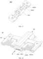
- FIG. 15 shows a structure of a sliding block 101221 according to an embodiment.
- an abutting portion 1012214 may be disposed on a side that is of the sliding block 101221 and that faces the main shaft assembly 102, and the abutting portion 1012214 may be configured to abut against the cam surface 10111 of the cam member 1011.
- a surface of the abutting portion 1012214 may be an arc surface or a spherical surface, so that a friction pair between the sliding block 101221 and the cam member 1011 is a rolling friction pair, to reduce wear of the sliding member 10122.
- the sliding block 101221 may be of an integral structure.
- the abutting portion 1012214 is a part of the sliding block 101221, to simplify a structure of the sliding member 10122.
- the abutting portion 1012214 and the sliding block 101221 may alternatively be of a split structure.
- the abutting portion 1012214 and the sliding block 101221 may be fastened through threading, snap-fitting, or the like.
- the abutting portion 1012214 may alternatively be disposed as the roller in the foregoing embodiment, and the roller is rotatably connected to the sliding block by using the roller shaft.
- a first sliding portion 10121111 and a second sliding portion 10121112 are respectively disposed on two opposite groove walls of the sliding groove 1012111, so that the sliding block 101221 stably slides in the sliding groove 1012111.
- the first sliding portion 10121111 may be disposed on a side that is of the first rotating arm 101213 and that faces the sliding groove 1012111
- the second sliding portion 10121112 may be disposed on a side that is of the second rotating arm 101214 and that faces the sliding groove 1012111.
- both FIG. 14 and FIG. 15 refer to both FIG. 14 and FIG. 15 .
- a third sliding portion 1012215 is disposed on a side that is of the sliding block 101221 and that faces the first rotating arm 101213, and a fourth rotating portion 101225 is disposed on a side that is of the sliding block 101221 and that faces the second rotating arm 101214.
- the third sliding portion 1012215 slidably cooperates with the first sliding portion 10121111
- the fourth sliding portion 1012216 slidably cooperates with the second sliding portion 10121112.
- the first sliding portion 10121111, the second sliding portion 10121112, the third sliding portion 1012215, and the fourth sliding portion 1012216 may be specifically disposed in a plurality of manners.
- the first sliding portion 10121111 and the second sliding portion 10121112 may be disposed as grooves, and the third sliding portion 1012215 and the fourth sliding portion 1012216 may be disposed as protrusions; or the first sliding portion 10121111 and the second sliding portion 10121112 may be disposed as protrusions, and the third sliding portion 1012215 and the fourth sliding portion 1012216 may be disposed as grooves; or the first sliding portion 10121111 and the fourth sliding portion 1012216 may be disposed as grooves, and the second sliding portion 10121112 and the third sliding portion 1012215 may be disposed as protrusions, provided that two sliding portions on a same side slidably cooperate.
- the sliding block 101221 may be further connected to an elastic element 101224, to implement reciprocal motion of the sliding member 10122 in the sliding groove 1012111 in a direction toward and away from the main shaft assembly 102.
- the elastic element 101224 is a spring
- a guide rod 1012212 may be further disposed on a side that is of the sliding block 101221 and that faces away from the main shaft assembly 102. In this way, the elastic element 101224 can be sleeved on the guide rod 1012212.
- a hollow region 1012213 may be further disposed on a side that is of the sliding block 101221 and that faces away from the main shaft assembly 102, and the guide rod 1012212 and the elastic element 101224 may be disposed in the hollow region 1012213.
- the elastic element 101224, the guide rod 1012212, and the hollow region 1012213 refer to the foregoing embodiment. Details are not described herein again.
- the sliding block 101221 may be of an integral structure.
- the hollow region 1012213 may be a groove disposed on the sliding block 101221.
- the third sliding portion 1012215 and the fourth sliding portion 1012216 are also a part of the sliding block 101221.
- the hollow region 1012213 may be a region formed by fixedly connecting a plurality of stoppers that form the sliding block 101221, and the third sliding portion 1012215 and the fourth sliding portion 1012216 each may be formed on a stopper on a corresponding side.
- one end that is of the first rotating arm 101213 and that is close to the main shaft assembly 102 may be rotatably connected to the main shaft assembly 102 by using a first rotating shaft 101216, so that the rotating member 10121 and the main shaft assembly 102 are rotatably connected.
- one end that is of the first rotating arm 101213 and that is close to the main shaft assembly 102 may be provided with a first through hole 1012131, the first rotating shaft 101216 penetrates through the first through hole 1012131, and two ends of the first rotating shaft 101216 are mounted on the main shaft assembly 102.
- An axis direction of the first rotating shaft 101216 is the same as the length direction of the main shaft assembly 102, the first rotating shaft 101216 may be fastened on the main shaft assembly 102, and the first rotating arm 101213 may rotate around the rotating shaft.
- the first rotating arm 101213 may alternatively be fixedly connected to the first rotating shaft 101216, and the first rotating shaft 101216 may be rotatably connected to the main shaft assembly 102 after being mounted on the main shaft assembly 102, so that the first rotating arm 101213 and the main shaft assembly 102 are rotatably connected.
- For a rotatable connection between the second rotating arm 101214 and the main shaft assembly 102 refer to a side of the first rotating arm 101213 . Details are not described herein again.
- first rotating arm 101213 and the second rotating arm 101214 each may be rotatably connected to the main shaft assembly 102 by using one first rotating shaft 101216, or may share one first rotating shaft 101216, to simplify the structure of the rotating shaft mechanism 10.
- first rotating arm 101213 and the second rotating arm 101214 are rotatably connected to the main shaft assembly 102 by using the first rotating shaft 101216, so that the rotating member 10121 is rotatably connected to the main shaft assembly 102 by using a solid shaft.
- the rotating member 10121 and the main shaft assembly 102 may alternatively be rotatably connected by using a virtual shaft, to implement the miniaturization design of the rotating shaft mechanism 10.
- damper assemblies 101 there may also be a plurality of damper assemblies 101, and the plurality of damper assemblies 101 are separately disposed on two sides that are of the main shaft assembly 102 and that are perpendicular to the length direction of the main shaft assembly 102. There may be a same quantity of damper assemblies 101 located on each of the two sides of the main shaft assembly 102. In this way, the damper assemblies 101 can provide almost a same damping force for two housings of the terminal device, to help improve the structural stability of the terminal device.
- damper assemblies 101 on the two sides of the main shaft assembly 102 may be disposed in a one-to-one correspondence or disposed in a staggered manner.
- damper assemblies 101 may alternatively be disposed in pairs, and two damper assemblies 101 disposed in pairs are separately disposed on the two sides that are of the main shaft assembly 102 and that are perpendicular to the length direction of the main shaft assembly 102.
- an end portion that is of the first rotating arm 101213 and that is configured to be rotatably connected to the main shaft assembly 102 may be further provided with a gear structure 1012132, and the gear structure 1012132 may be an independent structure and is fixedly connected to the first rotating arm 101213.
- the gear structure 1012132 may be directly formed on a surface of the end portion of the first rotating arm 101213, to simplify a structure of the first rotating arm 101213.
- One end that is of the second rotating arm 101214 and that is configured to be rotatably connected to a main shaft may also be provided with the gear structure 1012132.
- a gear structure 1012132 of a first rotating arm 101213 of one of the two damper assemblies 101 disposed in pairs can engage with a gear structure 1012132 of a second rotating arm 101214 of the other damper assembly 101.
- the structure of the first rotating arm 101213 and the structure of the second rotating arm 101214 may be the same. Therefore, in some possible embodiments, a gear structure 1012132 of a first rotating arm 101213 of one of the two damper assemblies 101 disposed in pairs may engage with a gear structure 1012132 of a first rotating arm 101213 of the other damper assembly 101.
- a gear structure 1012132 of a second rotating arm 101214 of one of the two damper assemblies 101 disposed in pairs may engage with a gear structure 1012132 of a first rotating arm 101213 or a second rotating arm 101214 on a corresponding side of the other damper assembly 101.
- the two damper assemblies 101 disposed in pairs synchronously rotate through engagement between gear structures 1012132 of rotating arms on a corresponding side.
- FIG. 16 shows a connection relationship between a first rotating arm 101213 and a second rotating arm 101214 of two damper assemblies 101.
- the other damper assembly 101 may be driven to move in a direction that is opposite or faces away, so that the two damper assemblies 101 synchronously rotate. This helps improve consistency of damping forces on the two sides of the rotating shaft mechanism 10, to improve the structural stability of the rotating shaft mechanism 10.
- One baffle plate 101217 may be disposed on each of two sides of the first rotating arm 101213 and the second rotating arm 101214 that engage with each other and in the length direction of the main shaft assembly 102, to improve reliability of a transmission relationship between the first rotating arm 101213 and the second rotating arm 101214 that engage with each other.
- the two baffle plates 101217 may be configured to limit motion of the gear structure 1012132 of the first rotating arm 101213 and motion of the gear structure 1012132 of the second rotating arm 101214 in the length direction of the main shaft assembly 102, so that an engagement length between the gear structure 1012132 of the first rotating arm 101213 and the gear structure 1012132 of the second rotating arm 101214 is long, to improve stability of motion transfer between the gear structure 1012132 of the first rotating arm 101213 and the gear structure 1012132 of the second rotating arm 101214.
- each baffle plate 101217 is further provided with a second through hole 1012171, so that a first rotating shaft 101216 of each rotating arm can pass through a corresponding second through hole 1012171 in a one-to-one correspondence, to limit a center distance between the two gear structures 1012132, and help improve reliability of motion transfer between the two gear structures 1012132.
- the main shaft assembly 102 may include a main outer shaft 1021 and a main inner shaft 1022, to adapt to a structural design of the damper assembly 101.
- the main inner shaft 1022 has a first surface 10222 configured to support the flexible display 40.
- the first surface 10222 may be an arc surface. In this way, when the flexible display 40 shown in FIG. 1 is folded, the first surface 10222 may be configured to support the flexible display 40.
- a radian of the first surface 10222 may be designed based on a bending radian of a bending part of the flexible display 40, to reduce a risk that the flexible display 40 is damaged when being pressed or pulled.
- FIG. 17 shows a structure of a main inner shaft according to another embodiment of this application.
- the cam member 1011 of the rotating assembly 1012 mentioned in the foregoing embodiment may be fastened on the main inner shaft 1022.
- the cam member 1011 and the main inner shaft 1022 may alternatively be of an integral structure, to simplify the structure of the rotating shaft mechanism 10, and improve the structural stability of the rotating shaft mechanism 10.
- the main inner shaft 1022 is provided with an opening groove 10223.
- an end portion of the first rotating arm 101213 and an end portion of the second rotating arm 101214 that are configured to be rotatably connected to the main shaft assembly 102 are mounted in corresponding opening grooves 10223.
- a groove wall of the opening groove 10223 in the length direction of the main shaft assembly 102 may be provided with a shaft hole 102231, the shaft hole 102231 may be but is not limited to a U-shaped hole, and two ends of the first rotating shaft 101216 of the first rotating arm 101213 and the second rotating arm 101214 may be mounted in one shaft hole 102231 in a one-to-one correspondence.
- the main outer shaft 1021 may be fastened to the main inner shaft 1022, and accommodation space for accommodating another component of the rotating shaft mechanism 10 may be enclosed between the main outer shaft 1021 and the main inner shaft 1022.
- the main outer shaft 1021 and the main inner shaft 1022 may be connected by using a fastener 103 such as a bolt or a screw, or may be fixedly connected by using a snap-fit. This constitutes no limitation.
- the main outer shaft 1021 may be disposed to be of a split structure, to prevent the first rotating shaft 101216 of the first rotating arm 101213 and the second rotating arm 101214 from falling off from the corresponding shaft hole 102231.
- the main outer shaft 1021 includes a plurality of mutually independent pressure caps 10211, and the pressure caps 10211 covers an opening of the shaft hole 102231, so that an end portion of the first rotating shaft 101216 is limited between the shaft hole 102231 and the pressure caps 10211.
- each pressure cap 10211 may be fixedly connected to the main inner shaft 1022 by using a fastener 103 such as a bolt or a screw, or by using a snap-fit, or the like. This constitutes no limitation.
- FIG. 18 is a schematic diagram of a partial structure of a rotating shaft mechanism 10 according to an embodiment of this application.
- the rotating shaft mechanism 10 shown in FIG. 18 is in an unfolded state.
- the sliding member 10122 elastically abuts against the cam surface 10111 of the cam member 1011 under an elastic force of the elastic element 101224.
- An abutting force formed through elastic abutting may be transformed into resistance of relative rotation of the cam member 1011 and the rotating assembly 1012, to generate the damping force between the main shaft assembly 102 and the damper assembly 101.
- the rotating shaft mechanism 10 can be maintained in the unfolded state, to provide enough support for the terminal device.
- FIG. 19a is a B-direction view of the rotating shaft mechanism 10 in FIG. 18 .
- the unfolded state is a common use state of the terminal device, in this state, the rotating shaft mechanism 10 needs to provide a large damping force to maintain flatness of the entire device.
- FIG. 19a to FIG. 19c are schematic diagrams of structures of a rotating shaft mechanism 10 at different folding degrees. It can be found, in comparison of the rotating shaft mechanism 10 at different folding degrees, that, when the rotating shaft mechanism 10 is at different folding degrees, the elastic element 101224 is compressed or stretched to different degrees, and therefore, stores different elastic forces, so that the rotating assembly 1012 is subject to different damping forces in a process in which the rotating assembly 1012 rotates relative to the cam member 1011, to achieve a variable damping effect of the rotating shaft mechanism 10.
- FIG. 20 is a schematic diagram of an operating force in a process in which a rotating shaft mechanism 10 is switched from an unfolded state to a folded state according to an embodiment of this application. It can be understood that, in FIG. 20 , a horizontal coordinate represents a process of switching from an unfolded state to a folded state, and a vertical coordinate represents a magnitude of the operating force.
- the unfolded state is a common use state of the terminal device, in this state, the rotating shaft mechanism 10 needs to provide a large damping force to maintain flatness of the entire device.
- the rotating member 10121 rotates around the main shaft assembly 102, and the sliding member 10122 moves along the cam surface 10111 of the cam member 1011 and compresses the elastic element 101224 under an action of the cam member 1011. Therefore, the elastic force of the elastic element 101224 and the specific form of the cam surface 10111 are properly designed, to effectively improve a comfort degree of folding operation experience of the terminal device, and further ensure a life of the damper assembly.
- FIG. 21a is a schematic diagram of a structure of a rotating shaft mechanism 10 according to still another embodiment of this application.
- FIG. 21b is a schematic diagram of a structure existing when the rotating shaft mechanism 10 in FIG. 21a is viewed from another perspective. In the embodiment shown in FIG. 21a and FIG. 21b , the rotating shaft mechanism 10 is in an unfolded state.
- FIG. 21c is a schematic diagram of a structure of a rotating shaft mechanism 10 in an intermediate state.
- the rotating shaft mechanism 10 may also include a main shaft assembly 102 and a damper assembly 101, and the damper assembly 101 is rotatably connected to the main shaft assembly 102.
- FIG. 22 is a schematic diagram of an exploded structure of the rotating shaft mechanism shown in FIG. 21a to FIG. 21c .
- the damper assembly 101 may further include a rotating assembly 1012 and a cam member 1011.
- the rotating assembly 1012 includes a rotating member 10121 and a sliding member 10122, and the rotating member 10121 may rotate around the main shaft assembly 102, to drive the entire rotating assembly 1012 to rotate around the main shaft assembly 102.
- FIG. 23 shows a structure of a rotating member 10121.
- the rotating member 10121 may include a body portion 101211 and a connecting portion 101212, the connecting portion 101212 is disposed on one side of the body portion 101211, and the connecting portion 101212 is fixedly connected to the body portion 101211.
- the rotating member 10121 may be of an integral structure, so that structural reliability of the rotating member 10121 can be effectively improved, to improve motion stability of the rotating member 10121.
- the rotating member 10121 may alternatively be of a split structure, and the body portion 101211 and the connecting portion 101212 may be fixedly connected by using a fastener 103 such as a bolt, so that a structure of the rotating member 10121 can be flexibly set.
- the connecting portion 101212 may be configured to be rotatably connected to the main shaft assembly 102 in FIG. 22 .
- the connecting portion 101212 may be disposed as an arc shaft.
- the main shaft assembly 102 may be provided with an arc groove 10221, and the arc groove 10221 and the arc shaft are disposed in a one-to-one correspondence.
- each arc shaft may be accommodated in a corresponding arc groove 10221, and an arc surface of the arc shaft may slide along a groove wall of the arc groove 10221, to implement relative rotation of the connecting portion 101212 and the main shaft assembly 102.
- the arc shaft and the arc groove 10221 slidably cooperate, to form a virtual shaft, so that the rotating member 10121 and the main shaft assembly 102 are rotatably connected by using the virtual shaft.
- a structure for rotatably connecting the rotating member 10121 and the main shaft assembly 102 can occupy small space of the main shaft assembly 102, to help implement miniaturization and a thin design of the rotating shaft mechanism 10.
- the rotating member 10121 and the main shaft assembly 102 may alternatively be rotatably connected by using a solid shaft, to effectively simplify the structure of the rotating shaft mechanism 10, and reduce management and control difficulty of a manufacturing process of the rotating shaft mechanism 10.
- the body portion 101211 of the rotating member 10121 in this embodiment is also provided with a sliding groove 1012111.
- the sliding member 10122 is accommodated in the sliding groove 1012111 and may slide in the sliding groove 1012111.
- an end portion of the sliding member 10122 may abut against a cam surface 10111 of the cam member 1011, and an abutting force generated when the end portion abuts against the cam surface 10111 may be transformed into a damping force output of the damper assembly 101 for output.
- the cam member 1011 is disposed on the rotating assembly 1012.
- the body portion 101211 of the rotating member 10121 is further provided with two mounting grooves 1012113.
- the two mounting grooves 1012113 are respectively located on two sides of the sliding groove 1012111.
- each mounting groove 1012113 may be connected to the sliding groove 1012111 through a via hole 1012114.
- FIG. 24 is a schematic diagram of a structure of a cam member 1011 according to an embodiment of this application.
- One end that is of the cam member 1011 and that is provided with the cam surface 10111 may extend into the via hole 1012114, and may move in the mounting groove 1012113 in a direction toward or away from the sliding groove 1012111.
- the cam member 1011 is further connected to an elastic element 101224, and the elastic element 101224 may apply, to the cam member 1011, an elastic force toward the sliding groove 1012111, to press the cam member 1011 toward the sliding member 10122.
- the elastic element 101224 may be disposed with reference to any one of the foregoing embodiments. Details are not described herein again.
- the elastic element 101224 is a spring
- a guide rod 1012212 is disposed on a side that is of the cam member 1011 and that faces away from the via hole 1012114
- the elastic element 101224 may be sleeved on the guide rod 1012212, to facilitate mounting of the elastic element 101224 and the cam member 1011, and further avoid a problem that arching, or the like occurs when the elastic element 101224 is elastically deformed. Therefore, reliability of sliding the cam member 1011 in the mounting groove 1012113 is improved.
- one end of the elastic element 101224 elastically abuts against a groove wall of the mounting groove 1012113, and the other end elastically abuts against the cam member 1011, to press the cam member 1011 toward the sliding groove 1012111.
- the sliding member 10122 may include a rotating portion 101225 and a sliding block 101221.
- the sliding block 101221 is rotatably connected to the rotating portion 101225, and the rotating portion 101225 is rotatably connected to the main shaft assembly 102.
- an extension direction of an axis around which the rotating portion 101225 rotates around the main shaft assembly 102 is the same as the length direction of the main shaft assembly 102.
- an axis around which the rotating portion 101225 rotates around the main shaft assembly 102 is parallel to but does not overlap an axis around which the connecting portion 101212 of the rotating member 10121 rotates around the main shaft assembly 102. In this way, in a process in which the rotating assembly 1012 rotates relative to the main shaft assembly 102, there may be a phase difference between the sliding member 10122 and the rotating member 10121, so that the sliding member 10122 may slide relative to the rotating member 10121.
- FIG. 25 shows a structure of a rotating portion 101225 according to an embodiment of this application.
- the rotating portion 101225 may be provided with a gear structure 1012252, and the gear structure 1012252 may be an independent structure and is fixedly connected to the rotating portion 101225.
- the gear structure 1012252 may be directly formed on a surface of an end portion of the rotating portion 101225, to simplify the structure of the rotating portion 101225.
- Gear structures 1012252 of rotating portions 101225 of two damper assemblies 101 in FIG. 22 that are disposed in pairs may engage with each other.
- the other damper assembly 101 may be driven to move in a direction that is opposite or faces away, so that the two damper assemblies 101 synchronously rotate. This helps improve consistency of damping forces on the two sides of the rotating shaft mechanism 10, to improve the structural stability of the rotating shaft mechanism 10.
- FIG. 26 is a diagram of a connection relationship between two rotating portions 101225 according to this application.
- FIG. 27 is an exploded diagram of a connection relationship between two rotating portions 101225 according to this application.
- one baffle plate 101217 may be disposed on each of two sides of two rotating portions 101225 that engage with each other and in the length direction of the main shaft assembly 102 shown in FIG. 22 , to improve reliability of a transmission relationship between the two rotating portions 101225 that engage with each other.
- the two baffle plates 101217 may be configured to limit motion, of gear structures 1012252 of the two rotating portions 101225 that engage with each other, in the length direction of the main shaft assembly 102, so that an engagement length between the gear structures 1012252 of the two rotating portions 101225 is long, to improve reliability of motion transfer between the gear structures 1012252 of the two rotating portions 101225 .
- each baffle plate 101217 is further provided with a second through hole 1012171, so that a second rotating shaft 1012251 of each rotating portion 101225 can pass through a corresponding second through hole 1012171, to limit a center distance between the two gear structures 1012252 that engage with each other, and help improve reliability of motion of the two gear structures 1012252.
- the sliding block 101221 may be rotatably connected to the rotating portion 101225 by using a third rotating shaft 1012217.
- FIG. 28 shows a structure of the sliding block 101221 according to a possible embodiment of this application.
- One end portion of the sliding block 101221 may be provided with a mounting hole 1012211, and two end portions of the third rotating shaft 1012217 each are mounted in one mounting hole 1012211.
- an end portion of the sliding block 101221 is provided with a concave portion, and the mounting hole 1012211 is disposed on a side face of the concave portion.
- a part of the rotating portion 101225 may extend into the concave portion, so that the rotating portion 101225 is rotatably connected to the sliding block 101221.
- a structure including the sliding block 101221 and the rotating portion 101225 may be compact, to help implement a miniaturization design of the rotating shaft mechanism 10.
- the first sliding portion 10121111, the second sliding portion 10121112, the third sliding portion 1012215, and the fourth sliding portion 1012216 may be specifically disposed in a plurality of manners.
- the first sliding portion 10121111 and the second sliding portion 10121112 may be disposed as grooves, and the third sliding portion 1012215 and the fourth sliding portion 1012216 may be disposed as protrusions; or the first sliding portion 10121111 and the second sliding portion 10121112 may be disposed as protrusions, and the third sliding portion 1012215 and the fourth sliding portion 1012216 may be disposed as grooves; or the first sliding portion 10121111 and the fourth sliding portion 1012216 may be disposed as grooves, and the second sliding portion 10121112 and the third sliding portion 1012215 may be disposed as protrusions, provided that two sliding portions on a same side slidably cooperate.
- the cam member 1011 is mounted in the mounting groove 1012113, and the cam member 1011 may extend into the via hole 1012114 and may move in the mounting groove 1012113 in a direction toward or away from the sliding groove 1012111. Still as shown in FIG. 28 , in this application, an end portion that is of the sliding block 101221 and that faces the cam member 1011 may be further provided with an inclined surface 1012219. As shown in both FIG. 22 and FIG. 28 , the cam surface 10111 of the cam member 1011 abuts against the inclined surface 1012219, to apply a pushing force to the sliding block 101221 in a direction away from the main shaft assembly 102. It can be understood that, the cam surface 10111 and the inclined surface 1012219 are properly designed, to adjust a damping force provided by the damper assembly 101.
- the inclined surface 1012219 may be a surface of a concave portion disposed on the protrusion.
- the cam member 1011 in FIG. 24 may be further provided with a boss 10112.
- the sliding block 101221 may limit motion of the boss 10112 in a direction toward a groove opening of the mounting groove 1012113 of the rotating member 10121, to limit the cam member 1011 in the mounting groove 1012113, and prevent the cam member 1011 from falling off from the mounting groove 1012113.
- the third sliding portion 1012215 and the fourth sliding portion 1012216 of the sliding block 101221 may be disposed as protrusions, and a protrusion on a corresponding side is located at a location that is on the boss 10112 and that is close to the groove opening of the mounting groove 1012113, to limit the boss 10112.
- FIG. 29 is a schematic diagram of a structure of a main shaft assembly 102 according to an embodiment of this application.
- the main shaft assembly 102 further includes a main inner shaft 1022 and a main outer shaft 1021.
- FIG. 30 is a schematic diagram of a structure of a main inner shaft 1022 according to an embodiment. Similar to the foregoing embodiments, the main inner shaft 1022 in this embodiment also has a first surface 10222 configured to support the flexible display 40. The first surface 10222 may be disposed with reference to the foregoing embodiments. Details are not described herein again.
- the main inner shaft 1022 is provided with an opening groove 10223, and the rotating portion 101225 of the sliding member 10122 may be mounted in the opening groove 10223.
- a groove wall of the opening groove 10223 in the length direction of the main shaft assembly 102 may be provided with a shaft hole 102231, and the shaft hole 102231 may be but is not limited to a U-shaped hole.
- Two ends of the second rotating shaft 1012251 of the rotating portion 101225 shown in FIG. 27 may be mounted in a corresponding shaft hole 102231.
- the main outer shaft 1021 may be fastened to the main inner shaft 1022, and accommodation space for accommodating another component of the rotating shaft mechanism 10 may be enclosed between the main outer shaft 1021 and the main inner shaft 1022.
- the main outer shaft 1021 and the main inner shaft 1022 may be connected by using a fastener such as a bolt or a screw, or may be fixedly connected by using a snap-fit. This constitutes no limitation.
- the main outer shaft 1021 may be disposed to be of a split structure, to avoid interference in motion of the rotating portion 101225.
- the main outer shaft 1021 includes a plurality of mutually independent pressure caps 10211.
- FIG. 31 is a schematic diagram of a structure of a pressure cap 10211 according to an embodiment.
- a structure of the pressure cap 10211 may be but is not limited to a panel shape.
- Each pressure cap 10211 is fastened to the main outer shaft 1021, and accommodation space is formed between each pressure cap 10211 and the main outer shaft 1021.
- a connecting portion 101212 of the rotating member 10121 may be accommodated in the accommodation space, and is rotatably connected to the main shaft assembly 102.
- the unfolded state is a common state of the rotating shaft mechanism 10, it can be understood from the descriptions of the specific structure of the rotating shaft mechanism 10 in the foregoing embodiments that, for the rotating shaft mechanism 10 in the unfolded state shown in FIG. 21a and FIG. 21b , the elastic element 101224 may push the cam member 1011 to press the sliding block 101221, so that the cam member 1011 elastically abuts against the sliding block 101221, and the elastic element 101224 is subject to a pushing force applied by the cam member 1011 in a direction away from the sliding block 101221.
- the cam surface 10111 of the cam member 1011 abuts against a location that is on the inclined surface 1012219 of the sliding block 101221 and that faces away from the via hole 1012114.
- a tilt angle of the inclined surface 1012219 is properly set, so that a pressing force from the cam member 1011 may be transformed into a pulling force applied to the sliding block 101221 in a direction away from the main shaft assembly 102 (a direction shown by an arrow in FIG. 21b ), to generate a damping force between the main shaft assembly 102 and the damper assembly 101.
- FIG. 32a shows a relative location relationship between a sliding block 101221 and a rotating member 10121 when a rotating shaft mechanism 10 is in an unfolded state according to an embodiment of this application.
- FIG. 32b and FIG. 32c each show a relative position relationship between a sliding block 101221 and a rotating member 10121 when a rotating shaft mechanism 10 is in an intermediate state at a different folding degree.
- a force exerted on the sliding block 101221 enables the sliding block 101221 to tend to slide in a direction away from the main shaft assembly 102, so that the entire rotating shaft mechanism 10 tends to rotate toward a side opposite to a folding direction of the rotating shaft mechanism 10.
- a rotation limiting structure is disposed between the rotating member 10121 and the main shaft assembly 102, and such a motion trend may enable the entire rotating shaft mechanism 10 to remain in the unfolded state even under a specific external force.
- FIG. 33 is a schematic diagram of an operating force in a process in which a rotating shaft mechanism 10 is switched from an unfolded state to a folded state. Because the unfolded state is a common use state of the rotating shaft mechanism 10, the rotating shaft mechanism 10 needs to provide a large damping force to maintain flatness of the entire device.
- the sliding block 101221 may slide, to push the cam member 1011 to press the elastic element 101224.
- FIG. 32a to FIG. 32c the sliding block 101221 may slide, to push the cam member 1011 to press the elastic element 101224.
- the damper assembly 101 may be integrated into another possible structure, for example, a structure configured to implement a direct connection between the rotating shaft mechanism 10 and a housing of a terminal device, to improve a structural integration degree of the rotating shaft mechanism 10, and meet a requirement for a miniaturization design of the rotating shaft mechanism 10.
- disposing of the damper assembly 101 may not depend on disposing of another structure, to decoupling the damper assembly 101 and the another structure, so that the damper assembly 101 is disposed more flexibly.
- the rotating shaft mechanism 10 provided in this application includes a plurality of damper assemblies 101
- the plurality of damper assemblies 101 may be disposed in a same manner, and may be the damper assembly 101 mentioned in any one of the foregoing embodiments of this application.
- the plurality of damper assemblies 101 may be disposed in different manners, and may be damper assemblies 101 mentioned in at least two of the foregoing embodiments of this application.
Landscapes
- Engineering & Computer Science (AREA)
- Theoretical Computer Science (AREA)
- Computer Hardware Design (AREA)
- General Engineering & Computer Science (AREA)
- Physics & Mathematics (AREA)
- General Physics & Mathematics (AREA)
- Human Computer Interaction (AREA)
- Mechanical Engineering (AREA)
- Microelectronics & Electronic Packaging (AREA)
- Signal Processing (AREA)
- Mathematical Physics (AREA)
- Pivots And Pivotal Connections (AREA)
- Telephone Set Structure (AREA)
Applications Claiming Priority (2)
| Application Number | Priority Date | Filing Date | Title |
|---|---|---|---|
| CN202110312420.3A CN115126770A (zh) | 2021-03-24 | 2021-03-24 | 一种转轴机构及终端设备 |
| PCT/CN2022/081769 WO2022199493A1 (zh) | 2021-03-24 | 2022-03-18 | 一种转轴机构及终端设备 |
Publications (2)
| Publication Number | Publication Date |
|---|---|
| EP4300254A1 true EP4300254A1 (de) | 2024-01-03 |
| EP4300254A4 EP4300254A4 (de) | 2024-08-28 |
Family
ID=83374123
Family Applications (1)
| Application Number | Title | Priority Date | Filing Date |
|---|---|---|---|
| EP22774154.3A Pending EP4300254A4 (de) | 2021-03-24 | 2022-03-18 | Drehwellenmechanismus und endgerätevorrichtung |
Country Status (4)
| Country | Link |
|---|---|
| US (1) | US20240015909A1 (de) |
| EP (1) | EP4300254A4 (de) |
| CN (1) | CN115126770A (de) |
| WO (1) | WO2022199493A1 (de) |
Cited By (1)
| Publication number | Priority date | Publication date | Assignee | Title |
|---|---|---|---|---|
| EP4561036A4 (de) * | 2023-02-16 | 2025-10-15 | Honor Device Co Ltd | Drehwellenstruktur und klappendgerät |
Families Citing this family (20)
| Publication number | Priority date | Publication date | Assignee | Title |
|---|---|---|---|---|
| EP4318181B1 (de) * | 2021-07-20 | 2025-09-17 | Samsung Electronics Co., Ltd. | Elektronische vorrichtung mit scharniermodul |
| CN115899062B (zh) * | 2021-09-30 | 2026-04-17 | 华为技术有限公司 | 折叠屏设备及铰链组件 |
| CN114244926B (zh) * | 2021-11-30 | 2022-08-26 | 荣耀终端有限公司 | 一种可折叠的电子设备 |
| CN117157692B (zh) * | 2022-03-29 | 2026-04-03 | 京东方科技集团股份有限公司 | 转轴机构及可折叠柔性显示装置 |
| US20230412716A1 (en) * | 2022-06-15 | 2023-12-21 | Anand Naishadh Mandaliya | Convertible smartphone case apparatus |
| CN116677703B (zh) * | 2022-11-21 | 2024-11-01 | 荣耀终端有限公司 | 转轴结构及电子设备 |
| CN116016735A (zh) * | 2022-12-26 | 2023-04-25 | 维沃移动通信有限公司 | 电子设备 |
| CN118283153A (zh) * | 2022-12-30 | 2024-07-02 | 华为技术有限公司 | 一种折叠装置及电子设备 |
| CN115978082B (zh) * | 2023-02-08 | 2023-08-11 | 荣耀终端有限公司 | 一种转动机构、支撑装置以及电子设备 |
| CN116221266B (zh) * | 2023-03-03 | 2023-11-07 | 荣耀终端有限公司 | 一种阻尼转轴机构及可折叠电子设备 |
| CN116320116A (zh) * | 2023-03-27 | 2023-06-23 | 联想(北京)有限公司 | 电子设备 |
| CN116576188B (zh) * | 2023-06-05 | 2025-11-14 | 维沃移动通信有限公司 | 铰链组件和电子设备 |
| CN116734139A (zh) * | 2023-06-07 | 2023-09-12 | 华为技术有限公司 | 转轴装置、电子设备及壳体 |
| CN116592046B (zh) * | 2023-06-14 | 2026-04-24 | 京东方科技集团股份有限公司 | 一种铰链装置和折叠显示设备 |
| CN119288971A (zh) * | 2023-07-10 | 2025-01-10 | 荣耀终端有限公司 | 转轴机构及电子设备 |
| CN117605752A (zh) * | 2023-11-23 | 2024-02-27 | 维沃移动通信有限公司 | 铰链机构及电子设备 |
| CN120100808A (zh) * | 2023-11-30 | 2025-06-06 | 荣耀终端股份有限公司 | 一种转轴机构、支撑装置以及折叠屏终端 |
| CN119267417B (zh) * | 2024-01-19 | 2026-04-28 | 荣耀终端股份有限公司 | 转轴机构和可折叠设备 |
| CN118811144B (zh) * | 2024-08-09 | 2026-04-07 | 杭州零零科技有限公司 | 可折叠的无人飞行器 |
| CN121738996A (zh) * | 2024-09-25 | 2026-03-27 | 华为技术有限公司 | 主轴、折叠机构及电子设备 |
Family Cites Families (39)
| Publication number | Priority date | Publication date | Assignee | Title |
|---|---|---|---|---|
| US10754377B2 (en) * | 2017-04-05 | 2020-08-25 | Microsoft Technology Licensing, Llc | Hinged device |
| TWM559431U (zh) * | 2017-05-19 | 2018-05-01 | Fositek Corp | 軟性顯示設備及支撐裝置 |
| KR102390038B1 (ko) * | 2017-10-31 | 2022-04-25 | 엘지전자 주식회사 | 더블힌지 모듈 및 이동 단말기 |
| KR20190067400A (ko) * | 2017-12-07 | 2019-06-17 | 주식회사 한빛티앤아이 | 폴더블 디스플레이 장치의 듀얼힌지장치 |
| TWI673545B (zh) * | 2018-06-21 | 2019-10-01 | 兆利科技工業股份有限公司 | 折疊式裝置的轉軸模組 |
| US10491725B1 (en) * | 2018-09-14 | 2019-11-26 | Motorola Mobility Llc | Hinged electronic device with moving support plates for a flexible display and corresponding systems |
| TWI718784B (zh) * | 2018-12-04 | 2021-02-11 | 仁寶電腦工業股份有限公司 | 樞紐組件及應用樞紐組件的電子裝置 |
| TWI681284B (zh) * | 2018-12-25 | 2020-01-01 | 富世達股份有限公司 | 樞轉機構及可撓式電子裝置 |
| CN209798368U (zh) * | 2019-01-28 | 2019-12-17 | 无锡小天鹅电器有限公司 | 阻尼器、门盖组件及洗衣机 |
| TWI710308B (zh) * | 2019-02-16 | 2020-11-11 | 兆利科技工業股份有限公司 | 折疊式裝置的轉軸模組(四) |
| KR102375556B1 (ko) * | 2019-04-30 | 2022-03-17 | 삼성전자주식회사 | 힌지 구조물 및 이를 포함하는 전자 장치 |
| US10545541B1 (en) * | 2019-05-06 | 2020-01-28 | Microsoft Technology Licensing, Llc | Hinged device |
| CN112153178A (zh) * | 2019-06-27 | 2020-12-29 | 华为技术有限公司 | 一种转轴机构及可折叠移动终端 |
| CN112243053B (zh) * | 2019-07-17 | 2026-02-03 | 华为技术有限公司 | 一种转轴机构及移动终端 |
| CN110442196B (zh) * | 2019-07-30 | 2025-05-06 | 华为技术有限公司 | 转动机构、折叠显示终端 |
| TWI709843B (zh) * | 2019-09-19 | 2020-11-11 | 富世達股份有限公司 | 軟性顯示屏幕之折收轉軸結構 |
| CN112767831B (zh) * | 2019-10-21 | 2024-06-04 | 三星显示有限公司 | 显示装置 |
| CN112995368B (zh) * | 2019-12-13 | 2021-12-21 | 华为技术有限公司 | 一种铰链和移动终端 |
| KR102798666B1 (ko) * | 2019-12-13 | 2025-04-18 | 후아웨이 테크놀러지 컴퍼니 리미티드 | 회전축 구조체 및 전자 장치 |
| CN111043149B (zh) * | 2019-12-20 | 2021-09-14 | 深圳市长盈精密技术股份有限公司 | 折叠铰链及折叠显示装置 |
| CN214274224U (zh) * | 2020-02-20 | 2021-09-24 | 信锦企业股份有限公司 | 折叠式电子装置 |
| CN212643301U (zh) * | 2020-07-08 | 2021-03-02 | 拓米(成都)应用技术研究院有限公司 | 一种可搭载小尺寸柔性屏的折叠铰链机构及折叠设备 |
| CN112901643B (zh) * | 2020-09-14 | 2022-05-24 | 华为技术有限公司 | 折叠装置及电子设备 |
| CN114006962B (zh) * | 2020-10-29 | 2022-09-23 | 华为技术有限公司 | 折叠机构及电子设备 |
| EP4194995B1 (de) * | 2020-11-06 | 2025-01-29 | Samsung Electronics Co., Ltd. | Elektronische vorrichtung mit flexibler anzeige |
| CN116635639A (zh) * | 2020-11-18 | 2023-08-22 | 三星电子株式会社 | 包括扭矩结构的电子设备 |
| EP4207144B1 (de) * | 2021-01-13 | 2025-03-12 | Samsung Electronics Co., Ltd. | Faltbare flexible anzeigevorrichtung und elektronische vorrichtung |
| CN214507124U (zh) * | 2021-02-08 | 2021-10-26 | 杭州安费诺飞凤通信部品有限公司 | 一种铰链及内折柔性屏移动终端 |
| CN114909388B (zh) * | 2021-02-10 | 2023-05-26 | 维沃移动通信有限公司 | 折叠机构及电子设备 |
| TWI751083B (zh) * | 2021-05-17 | 2021-12-21 | 富世達股份有限公司 | 雙軸同步式鉸鏈 |
| TWI764720B (zh) * | 2021-05-17 | 2022-05-11 | 富世達股份有限公司 | 雙軸同步式鉸鏈 |
| CN113194183B (zh) * | 2021-05-21 | 2023-08-22 | 维沃移动通信有限公司 | 折叠机构及电子设备 |
| CN113241011B (zh) * | 2021-06-02 | 2022-05-31 | 武汉华星光电半导体显示技术有限公司 | 折叠显示装置 |
| AU2022327017A1 (en) * | 2021-08-09 | 2024-02-22 | Samsung Electronics Co., Ltd. | Foldable electronic device |
| WO2023044910A1 (en) * | 2021-09-27 | 2023-03-30 | Boe Technology Group Co., Ltd. | Pivotable support apparatus and display apparatus |
| CN115037817B (zh) * | 2021-11-08 | 2023-05-05 | 荣耀终端有限公司 | 凸轮组件、折叠机构、终端设备及凸轮组件的制作方法 |
| CN117847075B (zh) * | 2022-01-18 | 2024-10-25 | 荣耀终端有限公司 | 一种转轴机构、支撑装置和折叠屏设备 |
| CN117015665B (zh) * | 2022-02-28 | 2026-04-14 | 京东方科技集团股份有限公司 | 转轴机构及电子设备 |
| KR20240031506A (ko) * | 2022-08-30 | 2024-03-08 | 삼성디스플레이 주식회사 | 힌지 및 이를 포함하는 폴더블 표시 장치 |
-
2021
- 2021-03-24 CN CN202110312420.3A patent/CN115126770A/zh active Pending
-
2022
- 2022-03-18 EP EP22774154.3A patent/EP4300254A4/de active Pending
- 2022-03-18 WO PCT/CN2022/081769 patent/WO2022199493A1/zh not_active Ceased
-
2023
- 2023-09-22 US US18/472,399 patent/US20240015909A1/en active Pending
Cited By (1)
| Publication number | Priority date | Publication date | Assignee | Title |
|---|---|---|---|---|
| EP4561036A4 (de) * | 2023-02-16 | 2025-10-15 | Honor Device Co Ltd | Drehwellenstruktur und klappendgerät |
Also Published As
| Publication number | Publication date |
|---|---|
| US20240015909A1 (en) | 2024-01-11 |
| CN115126770A (zh) | 2022-09-30 |
| EP4300254A4 (de) | 2024-08-28 |
| WO2022199493A1 (zh) | 2022-09-29 |
Similar Documents
| Publication | Publication Date | Title |
|---|---|---|
| EP4300254A1 (de) | Drehwellenmechanismus und endgerätevorrichtung | |
| US11914433B2 (en) | Hinge and mobile terminal | |
| EP4443012A1 (de) | Scharniermechanismus und elektronische vorrichtung | |
| US20250048572A1 (en) | Hinge mechanism and electronic device | |
| CN113202857A (zh) | 铰链、柔性显示面板及电子装置 | |
| CN116201808B (zh) | 铰链结构和电子设备 | |
| US12572183B2 (en) | Rotating shaft mechanism and electronic device | |
| EP4354835A1 (de) | Klappmechanismus und elektronische vorrichtung | |
| EP4545812A1 (de) | Faltbare elektronische vorrichtung und drehwellenmechanismus dafür | |
| US20250243895A1 (en) | Hinge mechanism and electronic device | |
| US12613561B2 (en) | Rotating shaft mechanism and electronic device | |
| CN218760886U (zh) | 折叠组件、折叠装置及电子设备 | |
| CN115250299B (zh) | 折叠机构及电子设备 | |
| US20250169001A1 (en) | Foldable electronic device and hinge mechanism thereof | |
| US20250169002A1 (en) | Hinge Mechanism and Electronic Device | |
| CN114584638B (zh) | 一种转轴机构及移动终端 | |
| US20250053205A1 (en) | Hinge mechanism and electronic device | |
| WO2025175732A1 (zh) | 一种键盘组件及电子设备 | |
| CN117478777A (zh) | 折叠机构和电子设备 | |
| CN119957602B (zh) | 转轴机构、可折叠壳体及可折叠电子设备 | |
| WO2025236657A1 (zh) | 一种配件装置及电子设备 | |
| WO2025145664A1 (zh) | 一种折叠设备及铰链机构 | |
| CN116641989A (zh) | 一种阻尼模块、转轴机构及电子设备 |
Legal Events
| Date | Code | Title | Description |
|---|---|---|---|
| STAA | Information on the status of an ep patent application or granted ep patent |
Free format text: STATUS: THE INTERNATIONAL PUBLICATION HAS BEEN MADE |
|
| PUAI | Public reference made under article 153(3) epc to a published international application that has entered the european phase |
Free format text: ORIGINAL CODE: 0009012 |
|
| STAA | Information on the status of an ep patent application or granted ep patent |
Free format text: STATUS: REQUEST FOR EXAMINATION WAS MADE |
|
| 17P | Request for examination filed |
Effective date: 20230927 |
|
| AK | Designated contracting states |
Kind code of ref document: A1 Designated state(s): AL AT BE BG CH CY CZ DE DK EE ES FI FR GB GR HR HU IE IS IT LI LT LU LV MC MK MT NL NO PL PT RO RS SE SI SK SM TR |
|
| DAV | Request for validation of the european patent (deleted) | ||
| DAX | Request for extension of the european patent (deleted) | ||
| A4 | Supplementary search report drawn up and despatched |
Effective date: 20240729 |
|
| RIC1 | Information provided on ipc code assigned before grant |
Ipc: G09F 9/30 20060101ALI20240723BHEP Ipc: H04M 1/02 20060101ALI20240723BHEP Ipc: G06F 1/16 20060101AFI20240723BHEP |