EP4300413A1 - Système de calcul destiné à la détermination de la position d'une ancre et procédé - Google Patents
Système de calcul destiné à la détermination de la position d'une ancre et procédé Download PDFInfo
- Publication number
- EP4300413A1 EP4300413A1 EP22181230.8A EP22181230A EP4300413A1 EP 4300413 A1 EP4300413 A1 EP 4300413A1 EP 22181230 A EP22181230 A EP 22181230A EP 4300413 A1 EP4300413 A1 EP 4300413A1
- Authority
- EP
- European Patent Office
- Prior art keywords
- anchor
- computer system
- construction site
- site object
- program code
- Prior art date
- Legal status (The legal status is an assumption and is not a legal conclusion. Google has not performed a legal analysis and makes no representation as to the accuracy of the status listed.)
- Withdrawn
Links
Images



Classifications
-
- G—PHYSICS
- G06—COMPUTING OR CALCULATING; COUNTING
- G06T—IMAGE DATA PROCESSING OR GENERATION, IN GENERAL
- G06T7/00—Image analysis
- G06T7/0002—Inspection of images, e.g. flaw detection
- G06T7/0004—Industrial image inspection
-
- G—PHYSICS
- G06—COMPUTING OR CALCULATING; COUNTING
- G06T—IMAGE DATA PROCESSING OR GENERATION, IN GENERAL
- G06T7/00—Image analysis
- G06T7/70—Determining position or orientation of objects or cameras
- G06T7/73—Determining position or orientation of objects or cameras using feature-based methods
- G06T7/74—Determining position or orientation of objects or cameras using feature-based methods involving reference images or patches
-
- G—PHYSICS
- G06—COMPUTING OR CALCULATING; COUNTING
- G06T—IMAGE DATA PROCESSING OR GENERATION, IN GENERAL
- G06T7/00—Image analysis
- G06T7/0002—Inspection of images, e.g. flaw detection
-
- G—PHYSICS
- G06—COMPUTING OR CALCULATING; COUNTING
- G06T—IMAGE DATA PROCESSING OR GENERATION, IN GENERAL
- G06T7/00—Image analysis
- G06T7/50—Depth or shape recovery
-
- G—PHYSICS
- G06—COMPUTING OR CALCULATING; COUNTING
- G06T—IMAGE DATA PROCESSING OR GENERATION, IN GENERAL
- G06T7/00—Image analysis
- G06T7/70—Determining position or orientation of objects or cameras
- G06T7/73—Determining position or orientation of objects or cameras using feature-based methods
-
- G—PHYSICS
- G06—COMPUTING OR CALCULATING; COUNTING
- G06T—IMAGE DATA PROCESSING OR GENERATION, IN GENERAL
- G06T2207/00—Indexing scheme for image analysis or image enhancement
- G06T2207/20—Special algorithmic details
- G06T2207/20081—Training; Learning
-
- G—PHYSICS
- G06—COMPUTING OR CALCULATING; COUNTING
- G06T—IMAGE DATA PROCESSING OR GENERATION, IN GENERAL
- G06T2207/00—Indexing scheme for image analysis or image enhancement
- G06T2207/20—Special algorithmic details
- G06T2207/20084—Artificial neural networks [ANN]
-
- G—PHYSICS
- G06—COMPUTING OR CALCULATING; COUNTING
- G06T—IMAGE DATA PROCESSING OR GENERATION, IN GENERAL
- G06T2207/00—Indexing scheme for image analysis or image enhancement
- G06T2207/20—Special algorithmic details
- G06T2207/20092—Interactive image processing based on input by user
Definitions
- the invention relates to a device for supporting the setting of an anchor, for example a screw or a nail.
- the anchor placed must maintain certain minimum distances from other, neighboring anchors and / or from the edges of construction site objects in which the anchor is to be placed. Otherwise, there is a risk of safety risks, for example because the anchor placed cannot develop the holding forces required for a specific application with sufficient security.
- a particular difficulty is that height differences between measuring points lead to measurement errors due to the view not being completely perpendicular to the length measuring device and the associated parallax.
- the object of the present invention is therefore to offer a device that enables an anchor to be safely placed in a construction site object. It is also desirable if the device can be used to easily check whether an anchor has already been set is set correctly.
- a computer system for determining the position of an anchor position relative to a construction site object for example a concrete element, comprising at least one camera, at least one output unit, at least one memory, and at least one microprocessor, wherein program code is stored in the memory for execution on the microprocessor , wherein the program code is set up to identify at least one type of a first anchor, and with the aid of the camera at least a distance between a first anchor position of the first anchor on a construction site object and / or for the first anchor and a position of a second anchor on the construction site object , for a second anchor on the construction site object and / or to an edge of the construction site object, and with the help of the output unit to output a signal and / or to store a signal in the memory, the signal being indicative of whether the distance is at least a defined target distance corresponds.
- the computer system can thus identify the type of anchor and, based on the type of anchor, use data associated with this type, in particular data relating to the geometry of the anchor.
- the camera can be used to take one or more shots.
- the program code can be set up to evaluate one or more recordings.
- the program code can be set up to determine the distance using image processing.
- the accuracy of the image processing in particular the distance determination, can be improved by taking the data associated with the type of anchor into account during the image processing. If the anchor is, for example, a screw anchor with a head, a known diameter of the head can be used to determine an image scale in the recordings.
- the resulting parallax offset can be used to generate depth information from the images.
- the camera has a depth sensor.
- the camera can, for example, have one or more time-of-flight-based depth sensors. The depth information required for evaluation can then be obtained directly from the recordings.
- Depth information can simplify the image processing described here and/or improve its accuracy.
- the camera is set up to only take a two-dimensional image.
- the camera can be and/or have a color image camera, a black and white camera and/or an event camera.
- the specific distance can be output as a signal on the output unit. A user of the computer system can thereby be informed whether the set anchor is set correctly or not.
- the anchor position is determined as a position at which the anchor should first be placed.
- the anchor position can, for example, correspond to the position of a borehole, in particular still to be created.
- the user can then be informed whether the position of the drill hole or the anchor position enables the anchor to be set correctly or whether, for example, another drill hole needs to be drilled in a different, more suitable position.
- the computer system can be used to ensure the quality of an anchor that has already been set and / or to quickly find suitable anchor positions.
- the first anchor and/or further anchors can be, for example, screw anchors, bolt anchors, impact anchors, in particular nails, or the like. You can put in specific ones Materials, in particular rocks, such as concrete, metals and / or wood, can be furnished.
- the first anchor can be a concrete screw anchor.
- the construction site object can then also be and/or comprise an object containing concrete, for example a reinforced concrete object.
- the computer system can be portable. For this purpose, it can have a weight of less than one kilogram, for example less than 0.5 kilograms. It can, for example, be designed as a portable telecommunications device, for example in the form of a so-called smartphone.
- the output unit can include a display unit. It can also include an input unit.
- the output unit can include a touchscreen.
- the computer system can be a multi-part computer system, in particular with a local and a remote computer unit.
- it can be and/or include a cloud-based computing system.
- the microprocessor can have one or more computing units. It is conceivable, for example, that one of the computing units is a linearly operating computing unit. At least one further computing unit can be a computing unit designed for parallel processing. This can, for example, be a graphics processor or be designed as part of a graphics processor.
- the microprocessor and/or the program code can be designed to have and/or train at least one machine learner.
- the machine learner can have a trainable neural network.
- the neural network can be convolution-based.
- the type of first anchor can be identified by recognizing a data matrix code, for example a QR code. This can preferably be arranged and/or formed on the first anchor, or at least on a packaging from which the first anchor is removed. Alternatively or additionally, it is also conceivable that a user of the computer system manually enters the type of the first anchor into the computer system in order to identify the type in this way.
- a data matrix code for example a QR code.
- the program code is set up based on the type of the first anchor to identify at least one structural feature of the anchor.
- the structural feature can, for example, be related to the geometry of the anchor. For example, it can be a dimension of the first anchor.
- anchors for example screw anchors
- a clear type assignment can often not be made solely on the basis of such geometric features.
- many types of different anchors, in particular anchors with different overall lengths have the same head diameter because the head shape and head diameter should meet certain standardizations.
- the program code is set up to evaluate at least one of the recorded images with regard to the presence of a lettering, for example a type designation.
- the type of the first anchor can be identified based on surface features that result from a specific manufacturing method of the first anchor in a manner that is as unique as possible and as specific as possible for the type of first attack.
- Such surface features can be and/or include, for example, certain scratch marks and/or engravings, for example in the head of the first anchor.
- the program code is set up to evaluate the at least one recording with regard to the presence of such specific surface features.
- the accuracy of the measurement using such image processing can be further increased by setting up the program code to use data linked to the type of the respective anchor to calibrate length measurements. For example, if the head diameter of the first anchor is known, then after identifying the head of the first anchor in a recording taken by the camera, this length can be used for calibration or at least used for calibration.
- the program code is set up to determine the target distance depending on the type of the first anchor and / or the type of the second anchor.
- data associated with the type of the first anchor can be used.
- the target distance can, for example, correspond to a distance between the first anchor and a second anchor.
- the target distance can correspond to a distance between the first anchor and an edge of the construction site object.
- the computer system can have a communication module for communication with a remote computer system.
- the program code can be set up to receive data, in particular regarding the type of the first anchor, from the remote computer system via the to access the communication module.
- the program code can be set up to retrieve the target distance.
- planning data is stored in the memory.
- the planning data can include data such as the target distance.
- the data can also include material properties, geometries, in particular target geometries, in particular of the construction site object, an intermediate object and / or the first and / or further anchors.
- the program code can be set up to load the planning data from the remote computer system into the memory using the communication module.
- the program code can also be set up to determine at least one material property of the construction site object. Depending on the specific material property, for example a type of material, the presence of cracks and/or other damage, particularly to the construction site object, the target distance can then be adjusted and/or determined.
- Anchors are often used to attach other objects to the construction site.
- Setting properties of the first anchor can then depend on the type of additional object(s). For example, a maximum possible setting depth of the first anchor can depend on the thickness of an object to be fastened. It is therefore advantageous if the program code is set up to identify at least one intermediate object to be arranged and/or arranged on the anchor and on the construction site object.
- the intermediate object can be, for example, a washer, a base plate and/or the like.
- the program code can be set up to use the camera to determine a setting depth of the first anchor in the construction site object.
- it can be set up to determine the setting depth by means of image processing of a camera recording. For this purpose, an overhang of the first anchor from the construction site object can be determined. If the total length of the first anchor is known, this setting depth can be determined from the total length minus the projection.
- the computer system can be used for quality assurance. It is therefore convenient if the program code is set up to determine the distance when the first anchor is already set. In this case, the program code is set up with an anchor that has already been set to identify and to check at least one minimum requirement, for example the target distance, for example of the first anchor from the edge of the construction site object.
- the program code can be set up to determine the distance starting from the first anchor position if the first anchor is not set.
- the program code can then be set up to use image processing to identify at least one recording from the camera, for example a borehole or a comparable anchor position at which the first anchor is to be placed.
- a user of the computer system marks an anchor position on the construction site object with a pointing device, for example a laser pointer. An anchor position marked in this way can then be identified by the program code or by the computer system and processed analogously to that described above.
- the computer system can therefore be used as an assembly aid.
- the program code is set up to determine a surface profile of the construction site object and/or the intermediate object using at least one input from a user of the computer system that characterizes the construction site object and/or the intermediate object.
- the program code can be further set up to query an input of at least three positions, in particular through graphical representation and selection with the aid of the output unit, in particular if the output unit also includes an input unit, for example in the form of a touchscreen.
- the program code can further be set up to record at least one image of the construction site object including the first anchor, the first anchor position, the second anchor and / or the second anchor position using the camera.
- the recording can be displayed on the output unit, in particular graphically.
- the program code can then be set up, for example, to query at least three input positions from the user.
- the input positions can be set by the user, for example, by tapping the corresponding positions on the touchscreen.
- the accuracy with which the construction site object and/or the intermediate object can be identified can be further improved.
- the invention also relates to a hand-held power tool with a computer system of the type described above and/or below.
- the hand tool can be a setting tool.
- it can be a bolt setting tool.
- the hand-held power tool is a screw-setting device, for example a cordless screwdriver and/or a cordless impact wrench.
- the hand-held power tool can therefore be set up in particular to ensure the quality of the fastening element that has been installed.
- the hand-held power tool includes a drill.
- the drill can be a hammer drill. It can be set up in particular for processing rock, for example concrete.
- the hand-held power tool can thus be set up to check an anchor position, in particular the position of a borehole, and/or to signal to a user of the hand-held power tool whether a planned position corresponds or would correspond to given requirements.
- the hand-held power tool can therefore be set up to signal a release signal to the user before the start of drilling a borehole in the case of the drill or before the start of setting a fastening element in the case of the setting tool when the hand-held power tool, in particular a tool tip of a tool arranged on the hand-held power tool, has a targets a position that meets the requirements and / or signals a blocking signal when the hand-held power tool, in particular the tool tip, targets a position that does not meet the requirements.
- a work process for example drilling a borehole or a Setting the fastener can be started or locked.
- the user of the hand-held power tool can check an anchor position or a position of an anchor without having to put down the hand-held power tool. For example, the user does not need to first put down the hand-held power tool, grab a smartphone or the like with the computer system, use the computer system and then switch back to the hand-held power tool again.
- This means work processes can be significantly simplified and accelerated. Such simplification and acceleration can also improve the user's willingness to actually carry out documentation tasks such as documenting, for example, the correct position of a set anchor.
- the computer system can be detachably arranged at an attachment point on the hand-held power tool. It is particularly conceivable that the attachment point corresponds to a battery interface, especially if the hand-held power tool can be operated wirelessly. The computer system can then be attached to the battery interface.
- the computer system can also have a battery interface for this purpose.
- the scope of the invention also includes a method for supporting the setting of a first anchor in a construction site object and / or for quality control of a first anchor placed in a construction site object, with a computer system of the type described above and / or below with the aid of a camera Computer system at least a distance between a first anchor position of the first anchor on a construction site object and / or for the first anchor and a position of a second anchor on the construction site object, for a second anchor on the construction site object and / or to an edge of the construction site object is determined, and whereby the determined distance is compared with a target distance.
- Fig. 1 shows a construction site situation 10 .
- This could be, for example, a building construction site.
- a construction site object 12 can be seen, in this case a concrete element.
- the concrete element can correspond, for example, to a base plate of a floor or a ceiling.
- a base plate 14 is mounted on the construction site object 12 using a first anchor 16 and a second anchor 18 .
- the first anchor 16 and the second anchor 18 are each placed into the construction site object 12 and through the base plate 14 via a first washer 20 and a second washer 22 , respectively.
- the first anchor 16 and the second anchor 18 are concrete screw anchors.
- the construction site object 12 has an edge 24 .
- a computer system 26 should now be used to check whether the first anchor 16 is set correctly. By way of example, it should be checked in particular whether an edge distance D1R of the first anchor 16 from the edge 24 reaches at least a target distance D1RS .
- the computer system 26 has an output unit 28 .
- the output unit 28 has a touchscreen. Graphical information can therefore be output on it; Positions or the like can also be entered by tapping.
- Positions can be entered two-dimensionally by a user by tapping the touchscreen at a location corresponding to the position to be entered. Alternatively or additionally, it is conceivable that the user points to a corresponding location in the room to enter the position and / or performs a gesture corresponding to the position. The displayed position and/or gesture can then be recorded and evaluated to determine the position.
- the computer system 26 also has a memory 30 .
- a program code 32 is stored in memory 30.
- the program code 32 can be executed on a microprocessor 34 of the computer system 26.
- the computer system 26 has a communication module 31 which is set up to establish a data connection to a remote computer system.
- the computer system 26 has a camera 36 .
- the camera 36 is designed as a stereoscopic camera.
- it has two recording units 38 , 40 .
- the recording units 38, 40 are arranged at a distance from one another on the computer system 26.
- the camera 36 as a whole is set up to take 40 images with depth information, i.e. three-dimensional images of an environment, from individual images from the recording units 38.
- the recording units 38, 40 can each be set up to record color images.
- FIG. 1 An example is in Fig. 1 shown that the output unit 28 shows an image 12 'of the construction site object 12. Furthermore, three input positions 42 can be seen. These three input positions 42 correspond to inputs from positions of a user (in Fig. 1 not shown), which the user assigns to the construction site object 12 or its image 12 '. One Entering an input position 42 can be done by the user touching the output unit 28, which is designed as a touchscreen, at the corresponding location.
- the computer system 26, in particular the program code 32 in conjunction with the microprocessor 34, is set up to evaluate images recorded by the camera 36, in particular moving image sequences. For example, types of the first anchor 16 and/or the second anchor 18 are identified and the course of the edge 24 is determined. Furthermore, the positions associated with the first anchor 16, the second anchor 18 and the edge 24 are determined. Alternatively or additionally, at least one type, for example the type of the first anchor 16, can also be entered manually. It is also conceivable that a barcode, data matrix code or the like that determines the type can be scanned for determination.
- a value of the target distance D1RS for this type is determined via the communication unit 31.
- the distance D1R is then determined from the specific positions, for example of the first anchor 16 and the course of the edge 24.
- the distance D1R is compared with the value of the target distance D1RS. Im in Fig. 1 In the case shown, the target distance D1RS is maintained, so that the computer system 26 outputs a positive test signal 43 on the output unit 28.
- minimum requirements other than the target distance D1RS for example minimum requirements for the second anchor 18, can also be checked in an analogous manner with the computer system 26.
- the program code 32 is set up, among other things, to evaluate recordings from the camera 36 using image processing.
- At least one machine learner is trained by the program code 32 in conjunction with the memory 30 and the microprocessor 34.
- An example of another minimum requirement is a minimum seeding depth with which the first Anchor 16 must protrude into the construction site object 12.
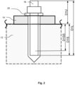
- FIG. 2 shows a partially sectioned view through the construction site object 12 with the first anchor 16 and the base plate 14 in between and the first washer 20.
- the first anchor 16 protrudes from the construction site object 12 with a projection D1U .
- the first anchor 16 has a length D1L depending on its type. It therefore projects into the construction site object 12 with a setting depth D1S corresponding to the difference between D1L and D1U.
- program code 32 ( Fig. 1 ) set up, the supernatant D1U using image processing from images taken by the camera 36 (see Fig. 1 ) to conclude the setting depth D1S.
- the program code 32 is also set up to compare the determined setting depth D1S with a minimum setting depth D1SS and to check whether the minimum setting depth D1SS is at least reached. According to the example Fig. 2 If this condition is met, the program code 32 can, when executed using the output unit 28, in turn produce a positive test signal 43 (see Fig. 1 ) spend. Otherwise it would trigger the output of a negative test signal, for example an error signal, in order to signal to the user that the first anchor 16 is not properly seated.
- a negative test signal for example an error signal
- Fig. 3 shows schematically a machine learner 44 and, by way of example, possible training data 46 for training the machine learner 44, possible input data 48 for carrying out at least one of the image processing processes and an example of possible output data 50 of the machine learner 44.
- the machine learner 44 can have at least one convolution-based neural network, for example a so-called “convolutional neural network”, hereinafter referred to as CNN, with several, for example 4 or 5, processing layers.
- the neural network can be set up to take control data sets into account in addition to image data as training data.
- the machine learner 44 can be trained to semantically segment recordings of construction site objects. Semantic segmentation can be an assignment of a bounding box and/or a reference point to a recognized object include.
- the machine learner 44 can be trained to identify construction site objects, for example concrete elements, intermediate objects, for example base plates, washers and / or different types of anchors.
- each type of anchor 50 to 150 different annotated views can be created, in particular with different light and/or contrast conditions and from different perspectives, preferably also partial views of the anchor and/or views from above or from obliquely above on a head or a free End of the anchor comprising, be provided as a basis for the training data.
- the training data can be enhanced by image rotations, brightness and/or contrast modifications.
- training data can also be compiled and, if necessary, expanded for the other objects or object classes that need to be identified.
- the machine learner 44 can also be trained to identify other everyday objects as well as objects that typically occur on construction sites but which cannot be related to the objects to be recognized, for example tools or machine tools, as objects to be excluded from further image processing.
- General image databases for everyday objects can also be used for such supplementary training.
- the training of the machine learner 44 can be done through supervised learning.
- the first washer 20 is arranged between the head of the first anchor 16 and the base plate 14 or the construction site object 12.
- the washer 20 is located outside the first anchor 16.
- the base plate 14 is between the construction site object 12 and the head of the first anchor 16 is arranged, whereas the construction site object 12 cannot be located between the base plate 14 and the head of the first anchor 16.
- the training data 46 can therefore also include such rules. Furthermore, the machine learner 44 can be set up to take such rules into account.
- the machine learner 44 can receive at least one recording, preferably several recordings, of the camera 36 as input data 48.
- the output data 50 resulting from the processing in the machine learner 44 can then include information on identified objects and/or bounding boxes 52 and/or reference points 54 on the identified objects. For reasons of simplification, in Fig. 3 only a bounding frame 52 and a reference point 54 are provided with a reference number.
- the program code 32 can then be set up, after identifying the first anchor 16 and the edge 24 of the construction site object 12 and the associated reference points 54, the distances required for the respective test, for example the edge distance D1R (see Fig. 1 ), to be calculated and with the assigned target distance D1RS (see Fig. 1 ) to compare. Depending on the outcome of the comparison, the program code 32 can then store a signal in the memory 30 and/or output it via the output unit 28.
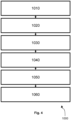
- Fig. 4 shows a method 1000 that can be implemented by the program code 32 in conjunction with the other elements of the computer system 26.
- the program code 32 can be set up to execute the method 1000.
- the method 1000 is described in more detail below using the previously introduced reference numbers for the elements of the computer system 26 and the construction site situation 10 explained. In variants of method 1000, one or more of the phases described below may be simplified or omitted.
- types of anchors to be tested are determined. For this purpose, for example, associated data matrix codes from packaging of the relevant anchor types can be scanned using the camera.
- Minimum requirements to be met by the anchors for example the target distance D1RS of the first anchor 15 to the edge 24, are loaded from a remote computer system, in particular a suitably filled database system, into the memory 30 with the aid of the communication module 31.
- the camera takes recordings in the form of moving images of the construction site object 12.
- the program code 32 derives a foreground/background distinction from the movement information contained therein.
- a reference plane including an origin point belonging to the reference plane is determined or defined as a reference plane to which three-dimensional positions of subsequently identified objects are related.
- one of the recordings is displayed on the output unit 28.
- a user of the computer unit 26 queries at least three input positions 42, which are located on the construction site object 12 and are therefore intended to characterize the construction site object 12. Using these input positions 42, the machine learner 44 determines the presence of the construction site object 12 and in particular the position of its edge 24.
- a recognition phase 1040 with the help of the machine learner 44 and using the input positions 42, further objects, in particular the base plate 14 and set anchors, in particular the first anchor 16 and the second anchor 18, are identified and associated reference frames 52 and reference points 54 are determined.
- the positions and orientations of the reference frames 52 and the reference points 54 are determined three-dimensionally with reference to the reference plane determined in the orientation phase 1020 and its origin point.
- a test phase 1050 distances between the identified anchors 16, 18 from one another and from the edge 24, including, for example, the edge distance D1R of the first anchor 16 to the edge 24, are calculated using the reference points 54 and, if applicable, the reference frame 52. These distances are then compared with minimum requirements present in memory 30. For example, the edge distance D1R is compared with the target distance D1RS.
- the positive or negative test signals are additionally stored in a documentation system so that they can be accessed again, for example, so that they can be made available again for later testing purposes.
- the documentation system can be located on a remote computer system and can be reached, for example, via the communication module 31.
- This variant of method 1000 thus enables quality control, for example of the first anchor 16 that has already been set.
- a variant of method 1000 can also enable a preliminary check of an anchor position. Unless otherwise described below, this variant can also include one or more of the previously described phases of the method 1000.
- the anchor position to be checked can be defined on the base plate 14 with a marking. It is also conceivable that the anchor position to be tested corresponds to a position of a borehole or the like.
- the type of anchor to be placed at the anchor position to be checked is preferably determined during the type identification phase 1010 by scanning a data matrix code or a barcode and/or by manual input.
- the detection phase 1040 is modified in such a way that instead of the first anchor 16 or instead of a set anchor, the anchor position to be checked is determined together with a reference point 54 assigned to it and/or a reference frame 52 as well as the associated positions. For this purpose, for example, the marking or the drill hole can be recognized.
- test phase 1050 is modified in such a way that the first anchor 16 or the corresponding anchor position to be tested takes place instead of identified anchors.
- edge distance D1R of the anchor position to be tested to the edge 24 can be calculated.
- the output of the comparison is again displayed on the output unit 28 using corresponding test signals.
- setting of the first anchor 16 is enabled or blocked depending on the outcome of the comparison. For example, in the event of a negative output, a hand-held power tool that was intended to create a drill hole at the marking can be stopped and/or blocked. Alternatively or additionally, in this case a setting device for setting the first anchor 16 can be stopped and/or blocked.
- Fig. 5 shows a section of such an output on the output unit 28 based on an output of a demonstrator system of the computer system 26.
- images 12' , 16' , 18' and 24' of the construction site object 12, the first anchor 16, the second anchor 18 and the edge 24 can be seen.
- Determined distances can also be seen as numerical values.
- the actual distances were also known in order to check any resulting measurement errors.
- the actual distances are in Fig. 5 given as numerical values in brackets, also in millimeters.
- test signals 56 associated with the distances which in this case correspond to positive test signals.
- the test signals 56 thus indicate that the anchors 16 and 18 are properly set.
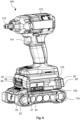
- Fig. 6 shows a hand tool 100.
- the hand tool 100 is designed as a screw setting device, in particular as a battery-operated impact wrench.
- the hand-held power tool 100 has a machine body 110 with a tool holder 112 for holding a screwing tool.
- the hand-held power tool 100 is set up to drive the tool holder 112 in a rotating and/or striking manner when an actuation button 114 is actuated.
- the hand-held power tool 100 has a motor arranged in the machine body 110.
- a fastening point 116 is formed on an underside of the machine body 110.
- the attachment point 116 enables a releasable attachment of an accumulator 118 to the machine body 110.
- the attachment point 116 can have a latching mechanism (in Fig. 6 cannot be displayed).
- the attachment point 116 also has an electrical interface (in Fig. 6 cannot be represented) through which electrical energy can be transferred to the motor.
- the attachment point, in particular its electrical interface, 116 can be set up for data transmission.
- a computer system 26 is arranged at the attachment point 116.
- the computer system 26 can correspond in structure and in terms of its functionalities to the computer systems 26 described above, unless otherwise described below.
- the computer system 26 is designed to carry out at least one of the variants of the method 1000 (see Fig. 4 ) furnished.
- the memory 30 in which the program code 32 is stored.
- the program code 32 can be executed on the microprocessor 34 of the computer system 26.
- the computer system 26 also has, among other things, the communication module 31, which in turn is set up to establish a data connection to a remote computer system.
- Fig. 6 For reasons of illustration, the elements 30, 31, 32, 34 are only shown very schematically, but are preferably located within a housing 120 of the computer system 26.
- the computer system 26 in turn has the camera 36 with the two recording units 38, 40.
- the computer system 26 also has an output unit 28 comprising a touchscreen, in particular a touchscreen that can be operated with gloves, on the back.
- Manual entries for example of an anchor type, can also be made via the output unit 28.
- a special feature of this computer system 26 is that it has a fit on the top that is complementary to the attachment point 116, so that it fits onto the attachment point 116, as in Fig. 6 shown, can be postponed.
- the underside On the underside it has a shape corresponding to the attachment point 116, so that the accumulator 118 can be detachably attached to this underside and as shown in Figure 6 is also detachably attached.
- the computer system 26 in this embodiment forms an intermediate module for arrangement between the accumulator 118 and the machine body 110.
- the electrical interface of the fastening point 116 is looped through from the underside of the computer system 26 to its upper side.
- this embodiment of the computer system 26 can also be used independently of the machine body 110, for example together with the accumulator 118.
- At least one of the elements 30, 31, 32 or 34 is arranged and/or designed outside the housing 120, in particular as part of the machine body 110.
- the microprocessor 34 is designed as a microprocessor that is shared or at least usable by the computer system 26 and the machine body 110.
- the computer system 26 is therefore also set up in this embodiment to support the setting of anchors in a construction site object, in particular for drilling a borehole at a specific anchor position, and / or for quality control of an anchor placed in a construction site object.
Landscapes
- Engineering & Computer Science (AREA)
- Computer Vision & Pattern Recognition (AREA)
- Physics & Mathematics (AREA)
- General Physics & Mathematics (AREA)
- Theoretical Computer Science (AREA)
- Quality & Reliability (AREA)
- Management, Administration, Business Operations System, And Electronic Commerce (AREA)
- Length Measuring Devices By Optical Means (AREA)
Priority Applications (4)
| Application Number | Priority Date | Filing Date | Title |
|---|---|---|---|
| EP22181230.8A EP4300413A1 (fr) | 2022-06-27 | 2022-06-27 | Système de calcul destiné à la détermination de la position d'une ancre et procédé |
| US18/870,586 US20250349031A1 (en) | 2022-06-27 | 2023-06-12 | Computer system for determining the position of an anchor, and method |
| PCT/EP2023/065637 WO2024002666A1 (fr) | 2022-06-27 | 2023-06-12 | Système informatique pour déterminer la position d'un boulon et procédé |
| EP23733653.2A EP4544492A1 (fr) | 2022-06-27 | 2023-06-12 | Système informatique pour déterminer la position d'un boulon et procédé |
Applications Claiming Priority (1)
| Application Number | Priority Date | Filing Date | Title |
|---|---|---|---|
| EP22181230.8A EP4300413A1 (fr) | 2022-06-27 | 2022-06-27 | Système de calcul destiné à la détermination de la position d'une ancre et procédé |
Publications (1)
| Publication Number | Publication Date |
|---|---|
| EP4300413A1 true EP4300413A1 (fr) | 2024-01-03 |
Family
ID=82321395
Family Applications (2)
| Application Number | Title | Priority Date | Filing Date |
|---|---|---|---|
| EP22181230.8A Withdrawn EP4300413A1 (fr) | 2022-06-27 | 2022-06-27 | Système de calcul destiné à la détermination de la position d'une ancre et procédé |
| EP23733653.2A Withdrawn EP4544492A1 (fr) | 2022-06-27 | 2023-06-12 | Système informatique pour déterminer la position d'un boulon et procédé |
Family Applications After (1)
| Application Number | Title | Priority Date | Filing Date |
|---|---|---|---|
| EP23733653.2A Withdrawn EP4544492A1 (fr) | 2022-06-27 | 2023-06-12 | Système informatique pour déterminer la position d'un boulon et procédé |
Country Status (3)
| Country | Link |
|---|---|
| US (1) | US20250349031A1 (fr) |
| EP (2) | EP4300413A1 (fr) |
| WO (1) | WO2024002666A1 (fr) |
Cited By (1)
| Publication number | Priority date | Publication date | Assignee | Title |
|---|---|---|---|---|
| DE102024114567A1 (de) * | 2024-05-24 | 2025-11-27 | Bayerische Motoren Werke Aktiengesellschaft | Testvorrichtung zum Durchführen eines Penetrationstests bei einem elektrischen Energiespeicher eines zumindest teilweise elektrisch betriebenen Kraftfahrzeugs |
Citations (3)
| Publication number | Priority date | Publication date | Assignee | Title |
|---|---|---|---|---|
| US20140365259A1 (en) * | 2011-11-29 | 2014-12-11 | Trimble Navigation Limited | In-field installation record of a project |
| DE102020115024A1 (de) * | 2020-06-05 | 2021-12-09 | Adolf Würth GmbH & Co. KG | Handgerät mit Sensoreinrichtung zum Charakterisieren eines bearbeiteten Untergrunds |
| EP4016212A1 (fr) * | 2020-12-17 | 2022-06-22 | Hilti Aktiengesellschaft | Système de machine-outil et procédé de commande d'une machine-outil mobile |
Family Cites Families (8)
| Publication number | Priority date | Publication date | Assignee | Title |
|---|---|---|---|---|
| US5881527A (en) * | 1995-04-21 | 1999-03-16 | Hasco, L.P. | Portable precast concrete slabs for storage facility |
| EP2735077B1 (fr) * | 2011-07-24 | 2017-06-21 | Makita Corporation | Système de charge de bloc-batterie portable et procédé de recharge de bloc-batterie |
| US10217031B2 (en) * | 2016-10-13 | 2019-02-26 | International Business Machines Corporation | Identifying complimentary physical components to known physical components |
| US11132479B1 (en) * | 2017-12-29 | 2021-09-28 | II John Tyson | Augmented reality system for component assembly and archival baseline clone |
| EP3861387B1 (fr) * | 2018-10-05 | 2025-05-21 | Magic Leap, Inc. | Rendu d'un contenu virtuel spécifique à un emplacement dans n'importe quel emplacement |
| US11423527B2 (en) * | 2018-11-20 | 2022-08-23 | Bnsf Railway Company | System and method for minimizing lost vehicle axel motion and filtering erroneous electrical signals |
| US11512956B2 (en) * | 2020-07-09 | 2022-11-29 | Trimble Inc. | Construction layout using augmented reality |
| US20220318459A1 (en) * | 2021-03-25 | 2022-10-06 | Nvidia Corporation | Robotic tactile sensing |
-
2022
- 2022-06-27 EP EP22181230.8A patent/EP4300413A1/fr not_active Withdrawn
-
2023
- 2023-06-12 EP EP23733653.2A patent/EP4544492A1/fr not_active Withdrawn
- 2023-06-12 WO PCT/EP2023/065637 patent/WO2024002666A1/fr not_active Ceased
- 2023-06-12 US US18/870,586 patent/US20250349031A1/en active Pending
Patent Citations (3)
| Publication number | Priority date | Publication date | Assignee | Title |
|---|---|---|---|---|
| US20140365259A1 (en) * | 2011-11-29 | 2014-12-11 | Trimble Navigation Limited | In-field installation record of a project |
| DE102020115024A1 (de) * | 2020-06-05 | 2021-12-09 | Adolf Würth GmbH & Co. KG | Handgerät mit Sensoreinrichtung zum Charakterisieren eines bearbeiteten Untergrunds |
| EP4016212A1 (fr) * | 2020-12-17 | 2022-06-22 | Hilti Aktiengesellschaft | Système de machine-outil et procédé de commande d'une machine-outil mobile |
Cited By (1)
| Publication number | Priority date | Publication date | Assignee | Title |
|---|---|---|---|---|
| DE102024114567A1 (de) * | 2024-05-24 | 2025-11-27 | Bayerische Motoren Werke Aktiengesellschaft | Testvorrichtung zum Durchführen eines Penetrationstests bei einem elektrischen Energiespeicher eines zumindest teilweise elektrisch betriebenen Kraftfahrzeugs |
Also Published As
| Publication number | Publication date |
|---|---|
| EP4544492A1 (fr) | 2025-04-30 |
| US20250349031A1 (en) | 2025-11-13 |
| WO2024002666A1 (fr) | 2024-01-04 |
Similar Documents
| Publication | Publication Date | Title |
|---|---|---|
| EP4016212A1 (fr) | Système de machine-outil et procédé de commande d'une machine-outil mobile | |
| DE102015105687B4 (de) | Roboter | |
| DE112017007903B4 (de) | Haltepositions- und Orientierungslehreinrichtung, Haltepositions- und Orientierungslehrverfahren und Robotersystem | |
| DE102010017763A1 (de) | Gerät zum Anzeigen des Werkzeugwegs für Werkzeugmaschinen | |
| EP4072807B1 (fr) | Procédé assisté par ordinateur et dispositif de commande de détermination de qualité de béton exposé | |
| WO2016015928A1 (fr) | Procédé de création d'un protocole de mesure et ordinateur pour mettre en œuvre un tel procédé | |
| DE102020131815A1 (de) | Anzeigevorrichtung und Anzeigeprogramm | |
| EP3403051B1 (fr) | Procédé et dispositif pour définir des données de consigne pour un mesurage d'une pièce à mesurer au moyen d'un appareil de mesure de coordonnées et/ou pour évaluer des résultats de mesure d'un mesurage d'une pièce mesurée au moyen d'un appareil de mesure de coordonnées | |
| DE102020115024A1 (de) | Handgerät mit Sensoreinrichtung zum Charakterisieren eines bearbeiteten Untergrunds | |
| EP3805693A1 (fr) | Validation des plans d'essai destinée à la mesure d'objet à l'aide d'un appareil de mesure de coordonnées | |
| EP4544492A1 (fr) | Système informatique pour déterminer la position d'un boulon et procédé | |
| WO2021083796A1 (fr) | Procédé assisté par ordinateur et système de détermination et de visualisation des flux de forces dans un échafaudage | |
| DE102021208279A1 (de) | Integration einer Risikobeurteilung einer Kollision zwischen einem robotischen Gerät und einer menschlichen Bedienperson | |
| DE102017119234A1 (de) | Produktionssystem mit einer funktion für das angeben der inspektionszeit für eine produktionsmaschine | |
| EP4316746A1 (fr) | Robot de construction doté d'une interface interchangeable, système de pièces et procédé d'agencement d'un système de pièces sur l'interface interchangeable | |
| DE102017005882B4 (de) | Verfahren zum Betrieb eines Roboters zur Überprüfung seiner Arbeitsumgebung | |
| DE102024100552B3 (de) | Verfahren zur Bestimmung wenigstens einer Absteckposition | |
| DE112021001048T5 (de) | Steuervorrichtung und steuerverfahren für einen roboter, robotersystem sowie vorrichtung und verfahren zum erzeugen eines betriebsprogramms eines roboters | |
| DE102017007078A1 (de) | Messsystem und Verfahren zur Bestimmung von 3D-Koordinaten von Messpunkten eines Objekts, insbesondere eines Umformwerkzeuges zur Herstellung von Fahrzeugen | |
| DE102017204629A1 (de) | System mit einem werkzeug und verfahren zum führen eines benutzers eines werkzeugs bei einer behandlung mindestens eines werkstücks | |
| DE102009027966A1 (de) | Richtwaage | |
| WO2008098826A1 (fr) | Procédé de détermination de points de mesure | |
| DE102019218381A1 (de) | Unterstützung von Arbeiten an Schalungen und Gerüsten | |
| DE102015206203A1 (de) | Bildmessvorrichtung | |
| DE112022000299T5 (de) | Numerische steuereinrichtung mit werkzeugmaschinen-einrichtungs-funktion und speichermedium |
Legal Events
| Date | Code | Title | Description |
|---|---|---|---|
| PUAI | Public reference made under article 153(3) epc to a published international application that has entered the european phase |
Free format text: ORIGINAL CODE: 0009012 |
|
| STAA | Information on the status of an ep patent application or granted ep patent |
Free format text: STATUS: THE APPLICATION HAS BEEN PUBLISHED |
|
| AK | Designated contracting states |
Kind code of ref document: A1 Designated state(s): AL AT BE BG CH CY CZ DE DK EE ES FI FR GB GR HR HU IE IS IT LI LT LU LV MC MK MT NL NO PL PT RO RS SE SI SK SM TR |
|
| STAA | Information on the status of an ep patent application or granted ep patent |
Free format text: STATUS: THE APPLICATION IS DEEMED TO BE WITHDRAWN |
|
| 18D | Application deemed to be withdrawn |
Effective date: 20240704 |