EP4300614A2 - Festkörpersekundärbatterie und verfahren zur herstellung davon - Google Patents
Festkörpersekundärbatterie und verfahren zur herstellung davon Download PDFInfo
- Publication number
- EP4300614A2 EP4300614A2 EP23178652.6A EP23178652A EP4300614A2 EP 4300614 A2 EP4300614 A2 EP 4300614A2 EP 23178652 A EP23178652 A EP 23178652A EP 4300614 A2 EP4300614 A2 EP 4300614A2
- Authority
- EP
- European Patent Office
- Prior art keywords
- active material
- anode active
- material layer
- solid
- anode
- Prior art date
- Legal status (The legal status is an assumption and is not a legal conclusion. Google has not performed a legal analysis and makes no representation as to the accuracy of the status listed.)
- Pending
Links
Images


Classifications
-
- H—ELECTRICITY
- H01—ELECTRIC ELEMENTS
- H01M—PROCESSES OR MEANS, e.g. BATTERIES, FOR THE DIRECT CONVERSION OF CHEMICAL ENERGY INTO ELECTRICAL ENERGY
- H01M4/00—Electrodes
- H01M4/02—Electrodes composed of, or comprising, active material
- H01M4/04—Processes of manufacture in general
- H01M4/0402—Methods of deposition of the material
- H01M4/0407—Methods of deposition of the material by coating on an electrolyte layer
-
- H—ELECTRICITY
- H01—ELECTRIC ELEMENTS
- H01M—PROCESSES OR MEANS, e.g. BATTERIES, FOR THE DIRECT CONVERSION OF CHEMICAL ENERGY INTO ELECTRICAL ENERGY
- H01M4/00—Electrodes
- H01M4/02—Electrodes composed of, or comprising, active material
- H01M4/36—Selection of substances as active materials, active masses, active liquids
- H01M4/362—Composites
- H01M4/366—Composites as layered products
-
- H—ELECTRICITY
- H01—ELECTRIC ELEMENTS
- H01M—PROCESSES OR MEANS, e.g. BATTERIES, FOR THE DIRECT CONVERSION OF CHEMICAL ENERGY INTO ELECTRICAL ENERGY
- H01M10/00—Secondary cells; Manufacture thereof
- H01M10/05—Accumulators with non-aqueous electrolyte
- H01M10/052—Li-accumulators
- H01M10/0525—Rocking-chair batteries, i.e. batteries with lithium insertion or intercalation in both electrodes; Lithium-ion batteries
-
- H—ELECTRICITY
- H01—ELECTRIC ELEMENTS
- H01M—PROCESSES OR MEANS, e.g. BATTERIES, FOR THE DIRECT CONVERSION OF CHEMICAL ENERGY INTO ELECTRICAL ENERGY
- H01M10/00—Secondary cells; Manufacture thereof
- H01M10/05—Accumulators with non-aqueous electrolyte
- H01M10/056—Accumulators with non-aqueous electrolyte characterised by the materials used as electrolytes, e.g. mixed inorganic/organic electrolytes
- H01M10/0561—Accumulators with non-aqueous electrolyte characterised by the materials used as electrolytes, e.g. mixed inorganic/organic electrolytes the electrolyte being constituted of inorganic materials only
- H01M10/0562—Solid materials
-
- H—ELECTRICITY
- H01—ELECTRIC ELEMENTS
- H01M—PROCESSES OR MEANS, e.g. BATTERIES, FOR THE DIRECT CONVERSION OF CHEMICAL ENERGY INTO ELECTRICAL ENERGY
- H01M4/00—Electrodes
- H01M4/02—Electrodes composed of, or comprising, active material
- H01M4/04—Processes of manufacture in general
- H01M4/0402—Methods of deposition of the material
- H01M4/0404—Methods of deposition of the material by coating on electrode collectors
-
- H—ELECTRICITY
- H01—ELECTRIC ELEMENTS
- H01M—PROCESSES OR MEANS, e.g. BATTERIES, FOR THE DIRECT CONVERSION OF CHEMICAL ENERGY INTO ELECTRICAL ENERGY
- H01M4/00—Electrodes
- H01M4/02—Electrodes composed of, or comprising, active material
- H01M4/04—Processes of manufacture in general
- H01M4/0402—Methods of deposition of the material
- H01M4/0416—Methods of deposition of the material involving impregnation with a solution, dispersion, paste or dry powder
-
- H—ELECTRICITY
- H01—ELECTRIC ELEMENTS
- H01M—PROCESSES OR MEANS, e.g. BATTERIES, FOR THE DIRECT CONVERSION OF CHEMICAL ENERGY INTO ELECTRICAL ENERGY
- H01M4/00—Electrodes
- H01M4/02—Electrodes composed of, or comprising, active material
- H01M4/13—Electrodes for accumulators with non-aqueous electrolyte, e.g. for lithium-accumulators; Processes of manufacture thereof
- H01M4/131—Electrodes based on mixed oxides or hydroxides, or on mixtures of oxides or hydroxides, e.g. LiCoOx
-
- H—ELECTRICITY
- H01—ELECTRIC ELEMENTS
- H01M—PROCESSES OR MEANS, e.g. BATTERIES, FOR THE DIRECT CONVERSION OF CHEMICAL ENERGY INTO ELECTRICAL ENERGY
- H01M4/00—Electrodes
- H01M4/02—Electrodes composed of, or comprising, active material
- H01M4/13—Electrodes for accumulators with non-aqueous electrolyte, e.g. for lithium-accumulators; Processes of manufacture thereof
- H01M4/133—Electrodes based on carbonaceous material, e.g. graphite-intercalation compounds or CFx
-
- H—ELECTRICITY
- H01—ELECTRIC ELEMENTS
- H01M—PROCESSES OR MEANS, e.g. BATTERIES, FOR THE DIRECT CONVERSION OF CHEMICAL ENERGY INTO ELECTRICAL ENERGY
- H01M4/00—Electrodes
- H01M4/02—Electrodes composed of, or comprising, active material
- H01M4/13—Electrodes for accumulators with non-aqueous electrolyte, e.g. for lithium-accumulators; Processes of manufacture thereof
- H01M4/139—Processes of manufacture
- H01M4/1391—Processes of manufacture of electrodes based on mixed oxides or hydroxides, or on mixtures of oxides or hydroxides, e.g. LiCoOx
-
- H—ELECTRICITY
- H01—ELECTRIC ELEMENTS
- H01M—PROCESSES OR MEANS, e.g. BATTERIES, FOR THE DIRECT CONVERSION OF CHEMICAL ENERGY INTO ELECTRICAL ENERGY
- H01M4/00—Electrodes
- H01M4/02—Electrodes composed of, or comprising, active material
- H01M4/13—Electrodes for accumulators with non-aqueous electrolyte, e.g. for lithium-accumulators; Processes of manufacture thereof
- H01M4/139—Processes of manufacture
- H01M4/1393—Processes of manufacture of electrodes based on carbonaceous material, e.g. graphite-intercalation compounds or CFx
-
- H—ELECTRICITY
- H01—ELECTRIC ELEMENTS
- H01M—PROCESSES OR MEANS, e.g. BATTERIES, FOR THE DIRECT CONVERSION OF CHEMICAL ENERGY INTO ELECTRICAL ENERGY
- H01M4/00—Electrodes
- H01M4/02—Electrodes composed of, or comprising, active material
- H01M4/36—Selection of substances as active materials, active masses, active liquids
- H01M4/362—Composites
- H01M4/364—Composites as mixtures
-
- H—ELECTRICITY
- H01—ELECTRIC ELEMENTS
- H01M—PROCESSES OR MEANS, e.g. BATTERIES, FOR THE DIRECT CONVERSION OF CHEMICAL ENERGY INTO ELECTRICAL ENERGY
- H01M4/00—Electrodes
- H01M4/02—Electrodes composed of, or comprising, active material
- H01M4/36—Selection of substances as active materials, active masses, active liquids
- H01M4/38—Selection of substances as active materials, active masses, active liquids of elements or alloys
- H01M4/40—Alloys based on alkali metals
- H01M4/405—Alloys based on lithium
-
- H—ELECTRICITY
- H01—ELECTRIC ELEMENTS
- H01M—PROCESSES OR MEANS, e.g. BATTERIES, FOR THE DIRECT CONVERSION OF CHEMICAL ENERGY INTO ELECTRICAL ENERGY
- H01M4/00—Electrodes
- H01M4/02—Electrodes composed of, or comprising, active material
- H01M4/36—Selection of substances as active materials, active masses, active liquids
- H01M4/48—Selection of substances as active materials, active masses, active liquids of inorganic oxides or hydroxides
- H01M4/485—Selection of substances as active materials, active masses, active liquids of inorganic oxides or hydroxides of mixed oxides or hydroxides for inserting or intercalating light metals, e.g. LiTi2O4 or LiTi2OxFy
-
- H—ELECTRICITY
- H01—ELECTRIC ELEMENTS
- H01M—PROCESSES OR MEANS, e.g. BATTERIES, FOR THE DIRECT CONVERSION OF CHEMICAL ENERGY INTO ELECTRICAL ENERGY
- H01M4/00—Electrodes
- H01M4/02—Electrodes composed of, or comprising, active material
- H01M4/36—Selection of substances as active materials, active masses, active liquids
- H01M4/58—Selection of substances as active materials, active masses, active liquids of inorganic compounds other than oxides or hydroxides, e.g. sulfides, selenides, tellurides, halogenides or LiCoFy; of polyanionic structures, e.g. phosphates, silicates or borates
- H01M4/583—Carbonaceous material, e.g. graphite-intercalation compounds or CFx
- H01M4/587—Carbonaceous material, e.g. graphite-intercalation compounds or CFx for inserting or intercalating light metals
-
- H—ELECTRICITY
- H01—ELECTRIC ELEMENTS
- H01M—PROCESSES OR MEANS, e.g. BATTERIES, FOR THE DIRECT CONVERSION OF CHEMICAL ENERGY INTO ELECTRICAL ENERGY
- H01M4/00—Electrodes
- H01M4/02—Electrodes composed of, or comprising, active material
- H01M2004/021—Physical characteristics, e.g. porosity, surface area
-
- H—ELECTRICITY
- H01—ELECTRIC ELEMENTS
- H01M—PROCESSES OR MEANS, e.g. BATTERIES, FOR THE DIRECT CONVERSION OF CHEMICAL ENERGY INTO ELECTRICAL ENERGY
- H01M4/00—Electrodes
- H01M4/02—Electrodes composed of, or comprising, active material
- H01M2004/026—Electrodes composed of, or comprising, active material characterised by the polarity
- H01M2004/027—Negative electrodes
-
- H—ELECTRICITY
- H01—ELECTRIC ELEMENTS
- H01M—PROCESSES OR MEANS, e.g. BATTERIES, FOR THE DIRECT CONVERSION OF CHEMICAL ENERGY INTO ELECTRICAL ENERGY
- H01M2300/00—Electrolytes
- H01M2300/0017—Non-aqueous electrolytes
- H01M2300/002—Inorganic electrolyte
-
- H—ELECTRICITY
- H01—ELECTRIC ELEMENTS
- H01M—PROCESSES OR MEANS, e.g. BATTERIES, FOR THE DIRECT CONVERSION OF CHEMICAL ENERGY INTO ELECTRICAL ENERGY
- H01M2300/00—Electrolytes
- H01M2300/0017—Non-aqueous electrolytes
- H01M2300/0065—Solid electrolytes
- H01M2300/0068—Solid electrolytes inorganic
- H01M2300/008—Halides
-
- Y—GENERAL TAGGING OF NEW TECHNOLOGICAL DEVELOPMENTS; GENERAL TAGGING OF CROSS-SECTIONAL TECHNOLOGIES SPANNING OVER SEVERAL SECTIONS OF THE IPC; TECHNICAL SUBJECTS COVERED BY FORMER USPC CROSS-REFERENCE ART COLLECTIONS [XRACs] AND DIGESTS
- Y02—TECHNOLOGIES OR APPLICATIONS FOR MITIGATION OR ADAPTATION AGAINST CLIMATE CHANGE
- Y02E—REDUCTION OF GREENHOUSE GAS [GHG] EMISSIONS, RELATED TO ENERGY GENERATION, TRANSMISSION OR DISTRIBUTION
- Y02E60/00—Enabling technologies; Technologies with a potential or indirect contribution to GHG emissions mitigation
- Y02E60/10—Energy storage using batteries
Definitions
- the present subject matter relates to an all-solid-state secondary battery and a method of preparing the same.
- lithium-ion batteries are being put to practical use not only in the fields of information-related devices and communication devices, but also in the fields of automobiles.
- safety is considered especially important as it is related to protecting life.
- Lithium-ion batteries currently available on the market use a liquid electrolyte containing a flammable organic solvent, and thus overheating and fire may occur in the case of a short circuit.
- all-solid-state secondary batteries using a solid electrolyte instead of a liquid electrolyte have been proposed.
- All-solid-state batteries do not contain a flammable organic solvent, and thus the possibility of fire or explosion may be greatly reduced even in the case of a short circuit. Therefore, such all-solid-state secondary batteries may significantly increase stability compared to lithium-ion batteries using a liquid electrolyte.
- an electrolyte used is solid, and thus lithium may locally be deposited at an interface between a solid electrolyte layer and an anode.
- the deposited lithium may grow and consequently penetrate a solid electrolyte layer, resulting in a short circuit of the battery.
- the effective interface area between the solid electrolyte layer and the anode becomes smaller than the actual contact area therebetween. Accordingly, as the interfacial resistance increases at the interface between the solid electrolyte layer and the anode, the internal resistance of the battery may increase, thereby degrading the cycle characteristics and capacity of the battery.
- an all-solid-state secondary battery in which a short circuit is prevented during charging and discharging, and cycle characteristics are improved.
- an all-solid-state secondary battery includes:
- a method of preparing the all-solid-state secondary battery includes
- first, second, third etc. may be used herein to describe various elements, components, regions, layers, and/or sections, these elements, components, regions, layers, and/or sections should not be limited by these terms. These terms are only used to distinguish one element, component, region, layer, or section from another element, component, region, layer, or section. Thus, a first element, component, region, layer, or section discussed below could be termed a second element, component, region, layer, or section without departing from the teachings of the present embodiments.
- Exemplary embodiments are described herein with reference to cross section illustrations that are schematic illustrations of idealized embodiments. As such, variations from the shapes of the illustrations as a result, for example, of manufacturing techniques and/or tolerances, are to be expected. Thus, embodiments described herein should not be construed as limited to the particular shapes of regions as illustrated herein but are to include deviations in shapes that result, for example, from manufacturing. For example, a region illustrated or described as flat may, typically, have rough and/or nonlinear features. Moreover, sharp angles that are illustrated may be rounded. Thus, the regions illustrated in the figures are schematic in nature and their shapes are not intended to illustrate the precise shape of a region and are not intended to limit the scope of the present claims.
- an anode structure for an all-solid-state secondary battery according to one or more embodiments, an all-solid-state secondary battery including the same, and a method of preparing the all-solid-state secondary battery will be described in more detail.
- An aspect provides an all-solid-state secondary battery including:
- the first anode active material layer is arranged adjacent to the solid electrolyte, and includes:
- anode including the carbon-containing anode active material in the all-solid-state secondary battery does not have an excellent binding force with a solid electrolyte, thus interfacial stability between the anode and the solid electrolyte may not be sufficient.
- an anode consists of a metal only
- current imbalance may occur due to agglomeration of particles in a process of alloying and dealloying with lithium during charging and discharging cycles, and accordingly, an alloy phase having low lithium diffusion may be formed and some of the high rate characteristics may be degraded.
- a metal diffuses within an electrode during charging and discharging cycles at a high temperature, the lifespan characteristics of an all-solid-state secondary battery may be degraded.
- the all-solid-state secondary battery is provided to solve the above-mentioned problems. Since the first anode active material layer in contact with the solid electrolyte includes the M 1 -M 2 O x composite, the Li-M 1 -M 2 O x composite, or a combination thereof, void formation or volume changes may be suppressed at high current density during charging and discharging cycles, and the all-solid-state secondary battery is controlled to have a pore structure with a large surface area, thereby obtaining an effect of widening a surface diffusion path, and thus a lithium diffusion rate increases in a solution with a pH of 7 or less.
- the movement of lithium ions from the first anode active material layer to the second anode active material layer may be controlled to be fast.
- an adhesion force between the solid electrolyte and the second anode active material layer arranged to be in contact with the anode current collector may be improved.
- the void formation at high current density during charging and discharging cycles may be suppressed, and thus the rate characteristics and the lifespan characteristics may be improved.
- the first metal M 1 may be a material inducing a reversible alloying/dealloying reaction with lithium
- M 2 O x which is an oxide of the second metal M 2
- M 2 O x may serve as a backbone matrix and may have a role in the uniform induction and the suppression of the void formation during charging and discharging cycles.
- the first metal (M 1 ) and the second metals (M 2 ) may each independently refer to an element that maintains a solid state in a solution with a pH of 7 or less, and may each have a lithium ion diffusivity of 1 ⁇ 10 -14 square centimeters per second (cm 2 /sec) or greater at 25°C.
- the term "metal" used herein includes at least one selected metal and metalloid.
- the first metal (M 1 ) and the second metals (M 2 ) may each be a metal that is alloyable with lithium
- the first metal and the second metal, M 1 and M 2 may be identical to (the same as) or different from each other, and may each independently be Si, Sn, Ag, Al, Zn, Ge, Mg, Te, Pb, As, Na, Bi, Ti, B, W, Mn, Fe, Ni, Cu, Cr, Zr, Ce, or a combination thereof.
- the M 1 -M 2 O x composite and the Li-M 1 -M 2 O x composite may each be prepared by coating and treating a metal (e.g., Te, Si, Ge, Sb, or the like) or a metal alloy (e.g., GeTe, or the like).
- a metal e.g., Te, Si, Ge, Sb, or the like
- a metal alloy e.g., GeTe, or the like.
- Component analysis of these composites may be performed by resonance Raman spectroscopy, X-photoelectron spectroscopy (XPS), transmission electron microscopy (TEM), energy dispersed X-ray (EDX) electron energy loss spectroscopy (EELS), inductively coupled plasma-mass spectroscopy (ICP-MS), or the like.
- XPS X-photoelectron spectroscopy
- TEM transmission electron microscopy
- EDX energy dispersed X-ray
- EELS energy loss spectros
- M 1 -M 2 O x composite and the Li-M 1 -M 2 O x composite for example, 0 ⁇ x ⁇ 2.
- the first and second metals M 1 and M 2 may be the same as or different from each other, and the composite may include, for example, Te-TeOx, wherein 0 ⁇ x ⁇ 2; Li a -Te x -Te y O 2 , wherein 0 ⁇ a ⁇ 5, 0 ⁇ x ⁇ 3, and 0 ⁇ y ⁇ 2; Li-Te-TeOx, wherein 0 ⁇ x ⁇ 2; Te-ZnOx; wherein 0 ⁇ x ⁇ 2; Li a -Te x -Zn y O 2 , wherein 0 ⁇ a ⁇ 5, 0 ⁇ x ⁇ 3, and 0 ⁇ y ⁇ 2; or Li-Te-ZnOx, wherein 0 ⁇ x ⁇ 2.
- an amount of M 2 O x may be about 0.05 parts by weight to about 50 parts by weight, based on 100 parts by weight of the total weight of the M 1 -M 2 O x composite.
- the amount of M 2 O x may be about 0.1 parts by weight to about 48 parts by weight, about 1 parts by weight to about 45 parts by weight, or about 5 parts by weight to about 43 parts by weight, based on 100 parts by weight of the total weight of the M 1 -M 2 O x composite.
- the amount of M 2 O x is within the ranges above, a binding force between the solid electrolyte and the anode active material layer may increase, and accordingly, the void formation at high current density during charging and discharging cycles may be suppressed, and the volume changes may be reduced. As a result, the all-solid-state secondary battery having improved rate characteristics and long-lifespan characteristics may be prepared.
- an amount of the lithium may be about 0.01 parts by weight to about 80 parts by weight, based on 100 parts by weight of a total weight of the Li-M 1 -M 2 O x composite
- an amount of M 1 may be about 10 parts by weight to about 70 parts by weight, based on 100 parts by weight of the total weight of the Li-M 1 -M 2 O x composite
- an amount of M 2 O x may be about 0.05 parts by weight to about 50 parts by weight, based on 100 parts by weight of the total weight of the Li-M 1 -M 2 O x composite.
- the binding force between the solid electrolyte and the anode active material layer may increase, and accordingly, the void formation at high current density during charging and discharging cycles may be suppressed, and the volume changes may be reduced. As a result, the all-solid-state secondary battery having improved rate characteristics and long-lifespan characteristics may be prepared.
- a thickness of the first anode active material layer may be about 10 nanometers (nm) to about 500 nm, and the first anode active material layer may include a plurality of pores (i.e., two or more pores).
- a second anode active material may be included in the pores of the first anode active material layer.
- at least one of the plurality of pores may include the second anode active material disposed therein.
- the first anode active material layer may includes a plurality of pores, at least one of the plurality of pores comprises the second anode active material disposed therein, and a porosity of the first anode active material layer is less than the porosity of the first anode active material layer that does not comprise the second anode active material disposed therein, or the first anode active material layer is non-porous by incorporation of the second anode active material.
- the second anode active material included in the second anode active material layer may be provided in at least one of the pores of the first anode active material layer so that porosity of the first anode active material layer may be reduced, or the pores may disappear (i.e., the first anode active material layer may become non-porous by incorporation of the second anode active material in the pores thereof).
- a size of the plurality of pores in the first anode active material layer may be about 3 nm to about 50 nm. In other words, at least one pore of the plurality of pores may have a size of about 3 nm to about 50 nm.
- the metals M 1 and M 2 may be selected differently from each other, and the composites may be, for example, Te-SiO x , wherein 0 ⁇ x ⁇ 2; or Li-Te-SiO x , wherein 0 ⁇ x ⁇ 2.
- a metal film may be further included or located between the second anode active material layer and the anode current collector.
- the all-solid-state secondary battery having improved rate characteristics and long lifespan characteristics may be prepared.
- a metal included in the film may include at least one of indium, silicon, gallium, tin, aluminum, titanium, zirconium, niobium, germanium, antimony, bismuth, gold, platinum, palladium, magnesium, silver, or zinc.
- a lithium film or a lithium alloy film may be further arranged between the second anode active material layer and the anode current collector.
- the lithium film may be a lithium precipitation layer produced after a charging (i.e., a first charging).
- the M 1 -M 2 O x composite in the first anode active material layer may include, for example, Te x -Te y O z , wherein 0 ⁇ x ⁇ 3, 0 ⁇ y ⁇ 2, and 0 ⁇ z ⁇ 2; Te x -Al y O z , wherein 0 ⁇ x ⁇ 3, 0 ⁇ y ⁇ 2, and 0 ⁇ z ⁇ 2; Se x -Se y O z , wherein 0 ⁇ x ⁇ 3, 0 ⁇ y ⁇ 2, and 0 ⁇ z ⁇ 2; Se x -Al y O z , wherein 0 ⁇ x ⁇ 3, 0 ⁇ y ⁇ 2, and 0 ⁇ z ⁇ 2; Sn x -Te y O z , wherein 0 ⁇ x ⁇ 3, 0 ⁇ y ⁇ 2, and 0 ⁇ z ⁇ 2; Te x -Sn y O z , wherein 0 ⁇ x ⁇ 3, 0 ⁇ y ⁇ 2, and 0 ⁇ z ⁇ 2; Te x -Sn y O
- the Li-M 1 -M 2 O x composite in the first anode active material layer may include, for example, Li a -Te x -Te y O Z , wherein 0 ⁇ a ⁇ 5, 0 ⁇ x ⁇ 3, 0 ⁇ y ⁇ 2, and 0 ⁇ z ⁇ 2; Li a -Te x -Al y O z , wherein 0 ⁇ a ⁇ 5, 0 ⁇ x ⁇ 3, 0 ⁇ y ⁇ 2, and 0 ⁇ z ⁇ 2; Li a -Se x -Se y O z , wherein 0 ⁇ a ⁇ 5, 0 ⁇ x ⁇ 3, 0 ⁇ y ⁇ 2, and 0 ⁇ z ⁇ 2; Li a -Se x -Al y O z , wherein 0 ⁇ a ⁇ 5, 0 ⁇ x ⁇ 3, 0 ⁇ y ⁇ 2, and 0 ⁇ z ⁇ 2; Li a -Sn x -Te y O z , wherein 0 ⁇ a ⁇ 5,
- the plurality of pores of the first anode active material layer may be formed partially or throughout the first anode active material layer.
- the plurality of pores may be formed by performing acid treatment, or by using a pore former.
- a size of the pores may be about 3 nm to about 50 nm, about 3.5 nm to about 45 nm, about 4 nm to about 40 nm, or about 5 nm to about 30 nm. It is to be understood that at least one pore of the plurality of pores may have the specified pores size.
- the size of the pores may be identified, for example, through a scanning electron microscope (SEM), a transmission electron microscope (TEM), or the like.
- SEM scanning electron microscope
- TEM transmission electron microscope
- the porosity of the first anode active material may be about 1% to about 90%, for example, about 20% to about 80%.
- porosity refers to a value obtained by dividing a total pore volume of the first anode active material by an apparent volume of the first anode active material.
- the second active material included in the second anode active material layer may be present in at least one of the pores of the first anode active material layer. Even when the second active material is present in at least one of the pores of the first anode active material layer, some of the pores of the first anode active material layer may still exist. In other words, not every pore of the plurality of pores may include the second active material.
- the second anode active material includes a carbon-containing anode active material, or a carbon-containing anode active material, and at least one of a metallic anode active material or a metalloid anode active material.
- the second anode active material may include either a carbon-containing anode active material, or the second anode active material may include both a carbon-containing anode active material and at least one of a metallic anode active material or metalloid anode active material.
- the second anode active material included in the second anode active material layer may be provided in at least one of the pores of the first anode active material layer so that porosity of the first anode active material layer may be reduced, or the pores may disappear, resulting in a non-porous structure.
- the second anode active material includes a carbon-containing anode active material, or a combination of a carbon-containing anode active material, and at least one of a metallic anode active material or a metalloid anode active material.
- pressed refers to a means of pressing an anode/solid electrolyte structure or an anode/solid electrolyte/cathode structure under an applied force.
- the first anode active material layer may include a metal or a metal-alloy oxide that reacts with lithium to form a lithium alloy or a lithium compound; lithium oxide including the metal or a metal-alloy; or a combination thereof.
- the first anode active material layer may include a metal alloy oxide containing an element present as an ion in a solution having a pH of 7 or less, and an element maintained in a solid state in a solution having a pH of 7 or less.
- an electrolyte having a pH of 7 or less selective dissolution may occur to prepare the first anode active material layer having a nanoporous structure.
- the element present as an ion in a solution having a pH of 7 or less may include, for example, Ge, Zn, Zr, Ga, Hf, Nb, In, Si, Cu, V, Cr, Ni, Mn, Fe, Co, Mg, Ca, Sr, or the like, or a combination thereof.
- the element maintained in a solid state in a solution having a pH of 7 or less include, for example, Sn, Ag, Al, Ge, Te, Pb, As, Na, Bi, Ti, B, W, Cu, Cr, Zr, Ce or a combination thereof.
- the metal alloy oxide may be an oxide including i) Ge, and ii) Te, Se, or a combination thereof.
- the metal alloy oxide may include, for example, a Ge-Te-O compound.
- a mixing molar ratio of Ge and Te may be stoichiometrically controlled in a range in which an alloy may be formed.
- the mixing molar ratio of Ge to Te may be about 2.5:1 to about 1:500, about 1:1 to about 1:500, about 1:1 to about 1:300, or about 1:1.5 to about 1:100. Based on these mixing polar ratios, for example, pores may be formed in the first anode active material layer by performing an acid treatment thereon.
- the mixing molar ratio of Ge to Te may be about 2.5:1 to about 1:500, about 1:1 to about 1:500, about 1:1 to about 1:300, or about 1:1.5 to about 1:100.
- the mixing molar ratio of Ge to Te may be identified by EDX or XPS.
- the mixing molar ratio of Ge to Te is within the ranges above, the all-solid-state secondary battery capable of maintaining high lithium diffusion and having improved rate characteristics and long lifespan characteristics by reducing the interfacial resistance between the anode and the solid electrolyte may be prepared.
- the first anode active material layer may be prepared by forming an alloy layer at the interface adjacent to the solid electrolyte, the alloy layer having low fluidity and less agglomeration of particles while maintaining high lithium diffusion during an alloying/dealloying process.
- the metal alloy may have low fluidity, and thus the original state thereof may be maintained during multiple charging and discharging cycles.
- the metal when the first anode active material layer consists of a metal having high fluidity, the metal may move towards the lithium metal during charging.
- the GeTe alloy may maintain an original layer shape thereof even during charging and discharging cycles.
- Such fluidity tendency increases when the eutectic temperature is low during alloying with lithium.
- the eutectic temperature during alloying with lithium may be, for example, greater than or equal to about 600°C, but embodiments are not limited thereto.
- the all-solid-state secondary battery including the first anode active material layer including the above-described metal alloy may have reduced the interfacial resistance of a battery cell, thereby improving the high rate characteristics.
- the current concentration may be continuously relieved under long-term operation at high current density, thereby improving the lifespan characteristics of the battery cell.
- the first anode active material layer may be formed of a metal alloy layer having fast lithium diffusion rates and capable of reversibly re-alloying with lithium after an alloying/dealloying process with lithium.
- the first anode active material layer may have lithium ion diffusivity that is controlled to be about 1 ⁇ 10 -14 square centimeters per second (cm 2 /sec) or greater at 25°C so that the lithium introduced into the first anode active material layer may move quickly to the second anode active material layer.
- the binding force of the first anode active material layer to the second anode active material layer may be further increased.
- the all-solid-state secondary battery having a long lifespan may be prepared while maintaining the binding force of the anode to the solid electrolyte during charging and discharging cycles.
- the all-solid-state secondary battery may have a structure in which the solid electrolyte, the first anode active material layer, which includes the M 1 -M 2 O x composite, the Li-M 1 -M 2 O x composite, or a combination thereof, the second anode active material layer, and Li, are stacked in the stated order.
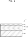
- FIG. 1 is a diagram showing a stacked structure of a multi-layered anode structure according to one or more embodiments.
- An anode structure 2 includes an anode 20 and a solid electrolyte 30, wherein the anode 20 has a structure in which a first anode active material layer 22 is arranged on an anode current collector 21 and a second anode active material layer 23 is arranged between the anode current collector 21 and the first anode active material layer 22. Pores may be formed in the first anode active material layer 22, and the first anode active material layer 22 may include a metal or a metal alloy, wherein the metal or the metal alloy may react with lithium to form a lithium compound or a lithium alloy.
- the lithium ion diffusivity of the first anode active material layer may be about 1 ⁇ 10 -14 cm 2 /sec or greater at 25°C, and may be controlled to be equal to or greater than the lithium ion diffusivity of the second anode active material layer.
- first anode active material layer 22 has a high lithium ion diffusivity by having a porous structure with a wide surface area, lithium introduced into the first anode active material layer 22 may move quickly to the second anode active material layer 23, so that local precipitation of lithium inside the first anode active material layer 22 or at the interface between the first anode active material layer 22 and the solid electrolyte 30 may be prevented or minimized.
- the lithium ion diffusivity of the first anode active material layer 22 at 25°C may be, for example, about 1 ⁇ 10 -14 cm 2 /sec or greater, about 1 ⁇ 10 -13 cm 2 /sec or greater, about 1 ⁇ 10 -12 cm 2 /sec or greater, about 1 ⁇ 10 -11 cm 2 /sec or greater, about 1 ⁇ 10 -10 cm 2 /sec or greater, or about 5 ⁇ 10 -10 cm 2 /sec or greater.
- the lithium ion diffusivity of the second anode active material layer 23 at 25°C may be, for example, about 1 ⁇ 10 -15 cm 2 /sec or greater, about 1 ⁇ 10 -14 cm 2 /sec or greater, about 1 ⁇ 10 -13 cm 2 /sec or greater, about 1 ⁇ 10 -12 cm 2 /sec or greater, about 1 ⁇ 10- 11 cm 2 /sec or greater, or about 5 ⁇ 10 -11 cm 2 /sec or greater.
- the first anode active material layer 22 may include the M 1 -M 2 O x composite, the Li-M 1 -M 2 O x composite, or a combination thereof.
- the lithium diffusion is high and the fluidity of particles is low, and thus stable interfacial contact may be maintained during charging and discharging cycles at a high rate.
- a phase with rapid lithium diffusion may be maintained.
- the first anode active material layer 22 may have a higher reduction potential of lithium ions than the solid electrolyte 30.
- the metal alloy included in the first anode active material layer 22 has a higher reduction potential of lithium ions at the time of charging than a solid electrolyte included in the solid electrolyte 30, a reductive decomposition reaction of the solid electrolyte may be suppressed. Accordingly, at the interface between the solid electrolyte 30 and the first anode active material layer 22, the decomposition of the solid electrolyte may be suppressed, and at the same time, the local precipitation of lithium may be suppressed, thereby forming a lithium precipitation layer with a uniform surface.
- the stability of the solid electrolyte 30 during charging and discharging cycles may be increased and the reversible precipitation/dissolution of the lithium precipitation layer may occur, and thus the short circuit of the all-solid-state secondary battery may be suppressed while having improved cycle characteristics.
- the reduction potential of lithium ions of the first anode active material layer refers to a potential for the metal or the metal alloy, which reacts with lithium to form a lithium alloy or a lithium compound, to reduce lithium ions to form a lithium-metal alloy such as a solid solution, wherein lithium is a material for forming the first anode active material layer 22. That is, the reduction potential of lithium ions refers to a potential maintained by the metal alloy during charging.
- the reduction potential of the solid electrolyte may refer to a potential at which a transition metal included in the solid electrolyte is reduced and a decomposition reaction of the solid electrolyte proceeds.
- the reduction potential of lithium ions of the first anode active material layer 22 may be, for example, about 0.05 Volts (V) to about 0.6 V (vs. Li + /Li).
- the reduction potential of lithium ions may refer to a reduction potential or a decomposition potential of the solid electrolyte.
- the reduction potential of LLZO may be about 0.05 V (vs. Li + /Li).
- a thickness of the first anode active material layer 22 may be about 10 nm to about 500 nm, about 15 nm to about 480 nm, about 20 nm to about 450 nm, about 30 nm to about 420 nm, and for example, about 50 nm to about 300 nm.
- an all-solid-state secondary battery having improved resistance and capacity characteristics may be prepared.
- the first anode active material layer 22 may be, for example, an inorganic layer that does not include an organic material.
- a side reaction caused by, for example, an organic material during charging and discharging cycles, may be suppressed.
- the Ge component of the metal alloy among the components of the first anode active material layer 22 may be mainly removed.
- the first anode active material layer may include a Li-Te-Ge compound, a Li-Te compound, a Li-Ge compound, a Li-Te-O compound, a Li-Te-Ge-O compound, or a combination thereof.
- the amount of Ge may be less than that of Te.
- the amount of Ge may be about 0.1 mole percent (mol%) to about 50 mol%, whereas the amount of Te may be about 20 mol% to about 90 mol%, each based on 100 mol% total. These amounts may be confirmed, for example, by EDX or XPS.
- a thickness ratio of the first anode active material layer 22 to the second anode active material layer 23 may be, for example, about 1:50 to about 1:100.
- FIG. 2 is a view of a structure of the all-solid-state battery according to one or more embodiments.
- the all-solid-state battery 1 includes a cathode 10 including a cathode active material layer 12; an anode 20; and a solid electrolyte 30 arranged between the cathode 10 and the anode 20, wherein the anode 20 includes: an anode current collector 21; a first anode active material layer 22 arranged on the anode current collector 21 and in contact with the solid electrolyte 30; and a second anode active material 23 arranged between the anode current collector 21 and the first anode active material layer 22.
- the first anode active material layer 22 may include a metal or a metal alloy that reacts with lithium to form a lithium compound or a lithium alloy
- the second anode active material layer 23 may include a carbon-containing anode active material only or a combination of a carbon-containing anode active material and at least one of a metal anode active material or metalloid anode active material.
- the lithium ion diffusivity of the first anode active material layer 22 may be controlled to be about 1 ⁇ 10 -14 cm 2 /sec or greater at 25°C. In addition, the lithium ion diffusivity of the first anode active material layer 22 may be controlled to be greater than or equal to that of the second anode active material layer 23.
- lithium introduced into the first anode active material layer 22 may move quickly to the second anode active material layer 23, and accordingly local precipitation of lithium inside the first anode active material layer 22 or at the interface between the first anode active material layer 22 and the solid electrolyte 30, may be prevented or minimized.
- the lithium ion diffusivity at 25°C of the first anode active material layer 22 may be, for example, about 1 ⁇ 10 -14 cm 2 /sec or greater, about 1 ⁇ 10 -13 cm 2 /sec or greater, about 1 ⁇ 10 -12 cm 2 /sec or greater, about 1 ⁇ 10 -11 cm 2 /sec or greater, about 1 ⁇ 10 -10 cm 2 /sec or greater, or about 5 ⁇ 10 -10 cm 2 /sec or greater.
- the lithium ion diffusivity at 25°C of the second anode active material layer 23 may be, for example, about 1 ⁇ 10 -15 cm 2 /sec or greater, about 1 ⁇ 10 -14 cm 2 /sec or greater, about 1 ⁇ 10 -13 cm 2 /sec or greater, about 1 ⁇ 10 -12 cm 2 /sec or greater, about 1 ⁇ 10 -11 cm 2 /sec or greater, or about 5 ⁇ 10 -11 cm 2 /sec or greater.
- the reduction potential of lithium ions of the composite constituting the first anode active material layer 22 may be controlled to be greater than the reduction potential of lithium ions of the solid electrolyte included in the solid electrolyte 30.
- a difference between the reduction potential of the lithium ions of the first anode active material layer 22 and the reduction potential of the solid electrolyte may be controlled to be, for example, about 0.01 V or greater, about 0.02 V or greater, about 0.05 V or greater, about 0.1 V or greater, about 0.2 V or greater, or about 0.3 V or greater.
- the reduction and decomposition reaction of the solid electrolyte may be effectively suppressed during charging and discharging.
- the reduction potential of lithium ions of the first anode active material layer 22 with respect to lithium metal may be, for example, about 0.05 V or greater, about 0.1 V or greater, about 0.2 V or greater, about 0.3 V or greater, about 0.4 V or greater, or about 0.5 V or greater.
- the reduction potential of the lithium ions of the metal alloy included in the first anode active material layer 22 may be, for example, about 0.05 V or greater, about 0.1 V or greater, about 0.2 V or greater, about 0.3 V or greater, about 0.4 V or greater, or about 0.5 V or greater.
- the reduction potential or reduction and decomposition potential of the solid electrolyte included in the solid electrolyte 30 with respect to lithium metal may be, for example, about 0.2 V or less, about 0.1 V or less, about 0.09 V or less, about 0.07 V or less, about 0.05 V or less, about 0.03 V or less, about 0.02 V or less, or about 0.01 V or less.
- solid electrolyte having a wide a wide electrochemically stable voltage window may be provided.
- the reduction potential of the first anode active material layer 22 may be greater than that of the second anode active material layer 23.
- the difference between the reduction potential of the lithium ions of the first anode active material layer 22 and the reduction potential of the lithium ions of the second anode active material layer 23 may be, for example, about 0.01 V or greater, about 0.02 V or greater, about 0.05 V or greater, about 0.1 V or greater, about 0.2 V or greater, or about 0.3 V or greater.
- a second metal included in the second anode active material layer 23 may be easily selected within a range having lower reduction potential of the lithium ions than the first anode active material layer 22 including a metal alloy.
- the reduction potential of the lithium ions of the Ge-Te metal alloy may be about 0.05 V to about 0.6 V.
- the reduction potential of lithium ions having silver (Ag) as the second metal may be about 0.2 V.
- the reduction potential of the lithium ions of the first anode active material layer 22 may be lower than the reduction potential of the lithium ions of the second anode active material layer 23.
- the reduction potential of the lithium ions of the first anode active material layer 22 may be higher than the reduction potential of the solid electrolyte, the reduction potential of the lithium ions of the first anode active material layer 22 may be lower than the reduction potential of the lithium ions of the second anode active material layer 23.
- the first anode active material layer 22 may include only a metal or a metal alloy, or may include a Li-containing metal or a Li-containing metal alloy layer.
- the thicknesses of the first anode active material layer 22 and the second anode active material layer 23 may each independently be, for example, about 50% or less, about 40% or less, about 30% or less, about 20% or less, or about 10% or less, of the thickness of the cathode active material layer 12.
- the all-solid-state secondary battery may have improved energy density.
- the thickness of the first anode active material layer 22 may be about 10 nm to about 500 nm, about 15 nm to about 480 nm, about 20 nm to about 450 nm, about 30 nm to about 420 nm, or for example, about 50 nm to about 300 nm.
- the thickness of the second anode active material layer 23 may be, for example, about 1 nm to 100 micrometer ( ⁇ m), about 10 nm to about 100 ⁇ m, about 100 nm to about 10 ⁇ m, about 1 ⁇ m to about 100 ⁇ m, about 5 ⁇ m to about 90 ⁇ m, about 10 ⁇ m to about 80 ⁇ m, about 15 ⁇ m to about 80 ⁇ m, about 20 ⁇ m to about 70 ⁇ m, about 20 ⁇ m to about 55 ⁇ m, about 1 nm to about 500 nm, about 10 nm to about 500 nm, about 10 nm to about 400 nm, about 10 nm to about 300 nm, about 10 nm to about 150 nm, or about 10 nm to about 100 nm.
- the first anode active material layer 22 and/or the second anode active material layer 23 may be arranged by, for example, a vacuum deposition method, a sputtering method, a plating method, or the like, but the method is not limited thereto. Any suitable method capable of forming an anode active material layer may be used.
- the second anode active material layer 23 may include, for example, an anode active material in the form of a particle and a binder.
- the average particle diameter of the anode active material in the form of particles included in the second anode active material layer 23 may be about 4 ⁇ m or less, about 3 ⁇ m or less, about 2 ⁇ m or less, about 1 ⁇ m or less, or about 900 nm or less.
- the average particle diameter of the anode active material in the form of particles may be, for example, about 10 nm to about 4 ⁇ m, about 10 nm to about 2 ⁇ m, about 10 nm to about 1 ⁇ m, or about 10 nm to about 900 nm.
- the average particle diameter of the second anode active material may be, for example, a median diameter (D50) measured by using a laser particle size distribution meter.
- the anode active material in the form of particles included in the second anode active material layer 23 may include, for example, i)a carbon-containing anode active material or ii) a carbon-containing anode active material, and at least one of a metal anode active material or a metalloid anode active material.
- the carbon-containing anode active material in the form of particles may be, in particular, amorphous carbon.
- the amorphous carbon may include, for example, at least one of carbon black (CB), acetylene black (AB), furnace black (FB), Ketjen black (KB), graphene, or the like, but is not necessarily limited thereto. Any suitable material available as amorphous carbon in the art may be used.
- the amorphous carbon may be carbon that does not have crystallinity or has very low crystallinity, and in this regard, may be distinguished from crystalline carbon or graphite-containing carbon.
- the metal or metalloid may include, for example, at least one of indium, silicon, gallium, tin, aluminum, titanium, zirconium, niobium, germanium, antimony, bismuth, zinc, gold, platinum, palladium, nickel, iron, cobalt, chromium, magnesium, cerium, cesium, or lanthanum.
- the second metal may include, for example, Au, Pt, Pd, Si, Ag, Al, Bi, Sn, Zn, Fe, Co, Cr, Cs, Ce, sodium (Na), potassium (K), calcium (Ca), yttrium (Y), Bi, tantalum (Ta), hafnium (Hf), barium (Ba), vanadium (V), strontium (Sr), La, or a combination thereof.
- Ni does not form an alloy with Li
- Ni is not a metal or metalloid anode active material.
- the second anode active material layer 23 may include, for example, one type of anode active material or a mixture of a plurality of different types of anode active material in the form of particles, among the anode active material in the form of particles.
- the first anode active material layer 22 may only include first particles consisting of amorphous carbon, or may further include second particles consisting of at least one metal of In, Si, Ga, Sn, Al, Ti, Zr, Nb, Ge, Sb, Bi, Zn, Au, Pt, Pd, Fe, Co, Cr, Mg, Ce, Cs, or La.
- the second anode active material layer 23 may include a mixture of first particles consisting of amorphous carbon, and second particles consisting of at least one metal of In, Si, Ga, Sn, Al, Ti, Zr, Nb, Ge, Sb, Bi, Zn, Au, Pt, Pd, Ni, Fe, Co, Cr, Mg, Ce, Cs, or La.
- the amount of the second particles may be about 8 wt% to about 60 wt%, about 10 wt% to about 50 wt%, about 15 wt% to about 40 wt%, or about 20 wt% to about 30 wt%, based on a total weight of the mixture of first particle and second particles. When the amount of the second particles is within the ranges above, for example, the cycle characteristics of the all-solid-state secondary battery 1 may be further improved.
- the second anode active material layer 23 may include only first particles consisting of amorphous carbon, or further include second particles consisting of at least one second metal of Au, Pt, Pd, Si, Ag, Al, Bi, Sn, or Zn.
- the second anode active material layer 23 may include a mixture of the first particles consisting of amorphous carbon, and the second particles consisting of a metal of Au, Pt, Pd, Si, Ag, Al, Bi, Sn, or Zn, wherein a mixing ratio of the amorphous carbon to the metal may be, for example, about 10:1 to about 1:2, about 5:1 to about 1:1, or about 4:1 to about 2:1.
- a mixing ratio is not limited within these ranges, and may be selected according to the required characteristics of the all-solid-state secondary battery 1.
- the anode active material included in the second anode active material layer 23 may include, for example, a mixture of the first particles consisting of amorphous carbon and the second particles consisting of a metal or a metalloid.
- the mixture may be a simple mixture of the first particles and the second particles, or a mixture of the first particles and the second particles that are physically bound together by a binder.
- the metal or the metalloid may include, for example, at least one of In, Si, Ga, Sn, Al, Ti, Zr, Nb, Ge, Sb, Bi, Au, Pt, Pd, Mg, Pd, Ag, or Zn.
- the metalloid may be, in other words, a semiconductor element.
- An amount of the second particle may be about 8 wt% to about 60 wt%, about 10 wt% to about 50 wt%, about 15 wt% to about 40 wt%, or about 20 wt% to about 30 wt%, based on the total weight of the mixture of first particle and second particles.
- the amount of the second particle is within the ranges above, the cycle characteristics of the all-solid-state secondary battery may be further improved.
- the second anode active material layer 23 may include, for example, a binder.
- the binder may be, for example, styrene-butadiene rubber (SBR), poly(tetrafluoroethylene), poly(vinylidene fluoride), polyethylene, vinylidene fluoride/hexafluoropropylene copolymer, polyacrylonitrile, poly(methyl methacrylate), or the like, but is not limited thereto. Any suitable material available as a binder may be used.
- the binder may be used alone, or may be used with a plurality of different binders.
- the second anode active material layer 23 When the second anode active material layer 23 includes the binder, the second anode active material layer 23 may be stabilized on the anode current collector 21. In addition, despite a change in volume and/or relative position of the second anode active material layer 23 during charging and discharging, cracking of the second anode active material layer 23 may be suppressed. For example, when the second anode active material layer 23 does not include the binder, the second anode active material layer 23 may be easily separated from the anode current collector 21.
- the second anode active material layer 23 may be prepared by, for example, coating the anode current collector 21 with a slurry in which a material constituting the second anode active material layer 23 is dispersed, and drying the coated anode current collector 21.
- the binder is included in the second anode active material layer 23, the anode active material may be stably dispersed in the slurry.
- clogging of the screen for example, clogging by an agglomerate of the anode electrode active material
- the anode current collector 21 may be formed of, for example, a material that does not react with lithium, in other words, a material that forms neither an alloy with lithium nor a compound with lithium.
- a material for forming the anode current collector 21 may be, for example, copper (Cu), stainless steel, Ti, Fe, Co, Ni, or the like, but is not limited thereto. Any suitable material available as an electrode current collector may be used.
- the anode current collector 21 may be formed of one of the above-described metals, or an alloy or coating material of two or more metals.
- the anode current collector 21 may be, for example, in the form of a plate or a foil.
- the second anode active material layer 23 may further include one or more additives, for example, a filler, a dispersant, an ion conductive agent, or the like, as used in a conventional all-solid-state battery.
- additives for example, a filler, a dispersant, an ion conductive agent, or the like, as used in a conventional all-solid-state battery.
- the thickness of the first anode active material layer 22 including the anode active material in the form of particles and/or the thickness of the second anode active material layer 23 may be, for example, about 50% or less, about 40% or less, about 30% or less, about 20% or less, or about 10% or less, of the thickness of the cathode active material layer 12.
- the all-solid-state secondary battery 1 may have improved energy density.
- a third anode active material layer may be arranged between the anode current collector 21 and the second anode active material layer 23 or between the first anode active material layer 22 and the second anode active material layer 23.
- the third anode active material layer may be a metal layer including lithium or a lithium alloy.
- the metal layer may include lithium or a lithium alloy.
- the third anode active material layer may be formed by a charging. Therefore, the third anode active material layer which is a metal layer including lithium may serve as, for example, a lithium reservoir.
- the lithium alloy may be, for example, a Li-Al alloy, a Li-Sn alloy, a Li-In alloy, a Li-Ag alloy, a Li-Au alloy, a Li-Zn alloy, a Li-Ge alloy, a Li-Si alloy, or the like, but is not limited thereto. Any suitable material alloyable with lithium may be used.
- the third anode active material layer may consist of lithium, one of the alloys above, or several kinds of alloys.
- a thickness of the third anode active material layer is not particularly limited, but may be, for example, about 1 ⁇ m to about 1,000 ⁇ m, about 1 ⁇ m to about 500 ⁇ m, about 1 ⁇ m to about 200 ⁇ m, about 1 ⁇ m to about 150 ⁇ m, about 1 ⁇ m to about 100 ⁇ m, or about 1 ⁇ m to about 50 ⁇ m.
- the third active material layer may be, for example, a metal foil having a thickness within the ranges above.
- the third anode active material layer 25 may be, for example, arranged between the anode current collector 21 and the second anode active material layer 23 or between the first anode active material layer 22 and the second anode active material layer 23, before assembling the all-solid-state secondary battery 1.
- the third anode active material layer may be, for example, precipitated between the anode current collector 21 and the second anode active material layer 23, or between the anode active material layer 22 and the second anode active material layer 23, by charging after the assembly of the all-solid-state secondary battery 1.
- the third anode active material layer is arranged between the anode current collector 21 and the second anode active material layer 23, or between the anode active material layer 22 and the second anode active material layer 23, before the assembly of the all-solid-state secondary battery 1, the third anode active material layer, which is a metal layer including lithium, may serve as a lithium reservoir. Accordingly, the cycle characteristics of the all-solid-state secondary battery 1 including the third anode active material layer may be further improved.
- a lithium foil may be arranged between the anode current collector 21 and the second anode active material layer 23, or between the first anode active material layer 22 and the second anode active material layer 23.
- the third anode active material layer is not included at the time of the assembly of the all-solid-state secondary battery 1, and thus the energy density of the all-solid-state battery 1 may increase.
- the charging capacity of the first anode active material layer 22 and the second anode active material layer 23 may be exceeded. That is, the first anode active material layer 22 and the second anode active material layer 23 may be overcharged.
- lithium may be absorbed in the first anode active material layer 22 and the second anode active material layer 23.
- the anode active materials included in the first anode active material layer 22 and the second anode active material layer 23 may form an alloy or compound with lithium ions that have migrated from the cathode 10.
- the first anode active material layer 22 and the second anode active material layer 23 are charged beyond the capacity thereof, for example, lithium may be precipitated on the rear surface of the second anode active material layer 23, i.e., between the anode current collector 21 and the second anode active material layer 23. Then, due to the precipitated lithium, a metal layer corresponding to the third anode active material layer may be formed.
- the first anode active material layer 22 and the second anode active material layer 23 are charged beyond the capacity thereof, for example, lithium may be precipitated on the front surface of the second anode active material layer 23, i.e., between the first anode active material layer 22 and the second anode active material layer 23. Then, due to the precipitated lithium, a metal layer corresponding to the third anode active material layer may be formed.
- the third anode active material layer may be a metal layer mainly including lithium (i.e., lithium metal).
- the anode active materials included in the first anode active material layer 22 and the second anode active material layer 23 consist of a material that forms an alloy or a compound with lithium.
- lithium included in the first anode active material layer 22, the second anode active material layer 23, and the third anode active material layer which is a metal layer may be ionized and move toward the cathode 10. Therefore, lithium may be used as the anode active material in the all-solid-state secondary battery 1.
- the first anode active material layer 22 and/or the second anode active material layer 23 coats the third anode active material layer
- the third anode active material layer 25 which is a metal layer may serve as a protective layer and serve to suppress the precipitation growth of lithium dendrites at the same time. Therefore, the short circuit and the capacity degradation of the all-solid-state secondary battery 1 may be suppressed, thereby improving the cycle characteristics of the all-solid-state secondary battery 1.
- the thickness of the first anode active material layer 22 may be, for example, about 5% to about 150%, about 10% to about 120%, about 20% to about 100%, about 30% to about 80%, or about 33% to about 66%, with respect to the thickness of the third anode active material layer in a state after charging.
- the function of the first anode active material layer 22 may not be appropriately performed.
- the energy density of the all-solid-state secondary battery 1 may be reduced.
- the anode current collector 21, the first anode active material layer 22, the second anode active material layer 23, and region therebetween may be, for example, lithium metal-free layers or regions that do not include lithium metal in an initial state or a post-discharge state of the all-solid-state secondary battery 1.
- the solid electrolyte 30 may include a solid electrolyte arranged between the cathode 10 and the anode 20.
- the solid electrolyte may include, for example, an oxide-containing solid electrolyte, a sulfide-containing solid electrolyte, or a combination thereof.
- the oxide-containing solid electrolyte may include one or more of Li 1+x+y Al x Ti 2-x Si y P 3-y O 12 , wherein 0 ⁇ x ⁇ 2 and 0 ⁇ y ⁇ 3; BaTiOs; Pb(Zr a Ti 1-a )O 3 , wherein 0 ⁇ a ⁇ 1 (PZT); Pb 1-x La x Zr 1-y Ti y O 3 , wherein 0 ⁇ x ⁇ 1 and 0 ⁇ y ⁇ 1 (PLZT); PB(Mg 3 Nb 2/3 )O 3 -PbTiO 3 (PMN-PT); HfO 2 ; SrTiO 3 ; SnO 2 ; CeO 2 ; Na 2 O; MgO; NiO; CaO; BaO; ZnO; ZrO 2 ; Y 2
- LiAlO 2 Li 2 O-Al 2 O 3 -SiO 2 -P 2 O 5 -TiO 2 -GeO 2 ; or Li 3+x La 3 M 2 O 12 , wherein M is Te, Nb, or Zr, and x is an integer from 1 to 10.
- the solid electrolyte may be prepared by a sintering method, or the like.
- the oxide-containing solid electrolyte may include a garnet-type solid electrolyte that is Li 7 La 3 Zr 2 O 12 (LLZO) and/or Li 3+x La 3 Zr 2-a M a O 12 (M-doped LLZO, M is Ga, W, Nb, Ta, or Al, and x is an integer from 1 to 10, 0.05 ⁇ a ⁇ 0.7).
- LLZO Li 7 La 3 Zr 2 O 12
- M-doped LLZO M is Ga, W, Nb, Ta, or Al
- x is an integer from 1 to 10, 0.05 ⁇ a ⁇ 0.7.
- the solid electrolyte may include, for example, a sulfide-containing solid electrolyte.
- the sulfide-containing solid electrolyte may include, for example, one or more of Li 2 S-P 2 S 5 , Li 2 S-P 2 S 5 -LiX, wherein X is a halogen, Li 2 S-P 2 S 5 -Li 2 O; Li 2 S-P 2 S 5 -Li 2 O-LiI; Li 2 S-SiS 2 ; Li 2 S-SiS 2 -LiI; Li 2 S-SiS 2 -LiBr; Li 2 S-SiS 2 -LiCI; Li 2 S-SiS 2 -B 2 S 3 -LiI; Li 2 S-SiS 2 -P 2 S 5 -LiI; Li 2 S-B 2 S 3 ; Li 2 S-P 2 S 5 -Z m S n , wherein m and n are positive numbers, and
- the sulfide-containing solid electrolyte may be, for example, prepared by treating a starting material, such as Li 2 S, P 2 S 5 , or the like) by a melting quenching method or a mechanical milling method, but embodiments are not limited thereto. Also, after such treatment, heat treatment may be performed.
- the sulfide-containing solid electrolyte may be amorphous or crystalline, or may be in a mixed state.
- the sulfide-containing solid electrolyte may include, for example, S, P, and Li, as at least constituent elements of the above-described sulfide-containing solid electrolyte material.
- the sulfide-containing solid electrolyte may be a material including Li 2 S-P 2 S 5 .
- a mixing molar ratio of Li 2 S to P 2 S 5 (Li 2 S:P 2 S 5 ) may be, for example, about 50:50 to about 90:10.
- the sulfide-containing solid electrolyte may include a compound having an argyrodite crystal-type structure.
- the compound having an argyrodite-type crystal structure may include, for example, one or more of Li 7-x PS 6-x Cl x , wherein 0 ⁇ x ⁇ 2; Li 7-x PS 6-x Br x , wherein 0 ⁇ x ⁇ 2; or Li 7-x PS 6-x I x , wherein 0 ⁇ x ⁇ 2.
- the sulfide-containing solid electrolyte included in the solid electrolyte may be an argyrodite-type compound including one or more of Li 6 PS 5 Cl, Li 6 PS 5 Br, or Li 6 PS 5 I.
- the solid electrolyte 30 may further include, for example, a binder.
- the binder included in the solid electrolyte 30 may be, for example, SBR, poly(tetrafluoroethylene), poly(vinylidene fluoride), polyethylene, or the like, or a combination thereof, but is not limited thereto. Any suitable material available as a binder may be used.
- the binder included in the solid electrolyte 30 may be the same as or different from the binders included in the cathode active material layer 12 and the first anode active material layer 22.
- the cathode 10 may include a cathode current collector 11 and a cathode active material layer 12.
- the cathode current collector 11 may be, for example, in the form of a plate or a foil, each including In, Cu, Mg, stainless steel, Ti, Fe, Co, Ni, Zn, Al, Ge, Li, or an alloy thereof.
- the cathode current collector 11 may be omitted.
- the cathode active material layer 12 may include, for example, a cathode active material.
- the cathode active material may be capable of reversibly absorbing or desorbing lithium ions.
- the cathode active material may include, for example, a lithium transition metal oxide, such as lithium cobalt oxide (LCO), a lithium nickel oxide, a lithium nickel cobalt oxide, a lithium nickel cobalt aluminum oxide (NCA), a lithium nickel cobalt manganese oxide (NCM), a lithium manganate, a lithium iron phosphate, or the like, a nickel sulfide, a copper sulfide, a lithium sulfide, an iron oxide, a vanadium oxide, or the like, but embodiments are not limited thereto. Any suitable material available as the cathode active material may be used.
- the cathode active material may be used alone or in a combination of two or more materials.
- the lithium transition metal oxide may be, for example, a compound represented by one of Li a A 1-b B b D 2 , wherein 0.90 ⁇ a ⁇ 1, and 0 ⁇ b ⁇ 0.5; Li a E 1-b B b O 2-c D c , wherein 0.90 ⁇ a ⁇ 1, 0 ⁇ b ⁇ 0.5, and 0 ⁇ c ⁇ 0.05; LiE 2-b B b O 4-c D c , wherein 0 ⁇ b ⁇ 0.5, and 0 ⁇ c ⁇ 0.05; Li a Ni 1-b-c Co b B c D ⁇ , wherein 0.90 ⁇ a ⁇ 1, 0 ⁇ b ⁇ 0.5, 0 ⁇ c ⁇ 0.05, and 0 ⁇ ⁇ ⁇ 2; Li a Ni 1-b-c Co b B c O 2- ⁇ F ⁇ , wherein 0.90 ⁇ a ⁇ 1, 0 ⁇ b ⁇ 0.5, 0
- a coating layer may be also added to the surface of the compound described above, and a mixture of the compound described above and a compound having a coating layer may be also used.
- a coating layer added to the surface of the compound described above may include, for example, a coating element compound such as an oxide of a coating element, a hydroxide of a coating element, an oxyhydroxide of a coating element, an oxycarbonate of a coating element, or a hydroxy carbonate of a coating element.
- a coating element compound constituting the coating layer may be amorphous or crystalline.
- the coating element included in the coating layer may include Mg, Al, Co, K, Na, Ca, Si, Ti, V, Sn, Ge, Ga, B, As, Zr, or a combination thereof.
- a method of forming the coating layer may be selected within a range that does not adversely affect the physical properties of the cathode active material.
- a coating method may include, for example, spray coating, dipping, or the like, but embodiments are not limited thereto.
- a specific coating method is well understood by those skilled in the art, and thus a detailed description thereof will be omitted.
- the cathode active material may include, for example, a lithium salt of a transition metal oxide having a layered rock salt type structure, among the lithium transition metal oxides described herein.
- layered rock salt type structure refers to, for example, a structure in which oxygen atomic layers and metal layers are alternately arranged regularly in the ⁇ 111> direction of a cubic rock salt type structure to form a two-dimensional plane by each of the atomic layers.
- cubic rock salt type structure refers to a NaCl type structure which is one type of crystal structures, and in detail, may refer to a structure in which a face centered cubic lattice (fcc) formed by respective anions and cations is misaligned from each other by 1/2 of the ridge of a unit lattice.
- fcc face centered cubic lattice
- the cathode active material includes a ternary lithium transition metal oxide having a layered rock salt type
- the all-solid-state secondary battery may have further improved energy density and thermal stability.
- the cathode active material may be covered by the coating layer as described herein.
- any suitable coating layer known for a cathode active material of an all-solid-state secondary battery may be used.
- the coating layer may be, for example, Li 2 O-ZrO 2 or the like.
- the cathode active material includes, for example, Ni as the ternary lithium transition metal oxide such as NCA or NCM
- the volume density of the all-solid-state secondary battery may increase so that the metal elution of the cathode active material may be reduced in a charged state. Consequently, the cycle characteristics of the all-solid-state secondary battery may be improved.
- the cathode active material may be in the form of, for example, a globular shape or an oval-sphere shape.
- a particle diameter of the cathode active material is not particularly limited and may be within a range applicable to a conventional all-solid secondary battery.
- the amount of the cathode active material in the cathode 10 is not particularly limited and may be within a range applicable to a cathode of a conventional all-solid-state battery.
- the cathode 10 may further include, in addition to the cathode active material, one or more additives such as a conductive material, a binder, a filler, a dispersant, an ion conductive auxiliary agent, or the like.
- the conductive material may include, for example, at least one of graphite, carbon black, acetylene black, Ketjen black, carbon fiber, metal powder, or the like.
- the binder may include, for example, at least one of SBR, poly(tetrafluoroethylene), poly(vinylidene fluoride), polyethylene, or the like.
- any suitable material generally used for a solid secondary battery may be used.
- the cathode 10 may further include a solid electrolyte.
- the solid electrolyte included in the cathode 10 may be similar to or different from the solid electrolyte included in the solid electrolyte 30. Details on the solid electrolyte may be understood by referring to the solid electrolyte 30.
- the solid electrolyte included in the cathode 10 may include, for example, an oxide-containing solid electrolyte, a sulfide-containing solid electrolyte, or a combination thereof.
- an oxide-containing solid electrolyte for use as the sulfide-containing solid electrolyte and the oxide-containing solid electrolyte, the sulfide-containing solid electrolyte and the oxide-containing solid electrolyte used for the solid electrolyte may be used.
- the cathode 10 may be, for example, impregnated with a liquid electrolyte.
- the liquid electrolyte may include a lithium salt and one or more of an ionic liquid or a polymer ionic liquid.
- the liquid electrolyte may be non-volatile.
- the ionic liquid may have a melting point that is less than room temperature, and may refer to a salt in a liquid state at room temperature or a molten salt at room temperature, each consisting of only ions.
- the ionic liquid may include a) one or more cations that are an ammonium cation, a pyrrolidinium cation, a pyridinium cation, a pyrimidinium cation, an imidazolium cation, a piperidinium cation, a pyrazolium cation, an oxazolium cation, a pyridazinium cation, a phosphonium cation, a sulfonium cation, a triazolium cation, or a combination thereof; or b) one or more anions that are BF 4 - , PF 6 - , AsF 6- , SbF 6 - , AlCl 4 - , HSO 4 - , ClO 4 - , CH 3 SO 3 - , CF 3 CO 2 - , Cl - , Br-, I - , SO 4 - , CF 3 SO 3
- the ionic liquid may include one or more of, for example, N-methyl-N-propylpyrrolidinium bis(trifluoromethanesulfonyl)imide, N-butyl-N-methylpyrrolidium bis(3-trifluoromethylsulfonyl)imide, 1-butyl-3-methylimidazolium bis(trifluoromethylsulfonyl)imide, or 1-ethyl-3-methylimidazolium bis(trifluoromethylsulfonyl)imide.
- the polymer ionic liquid may include a repeating unit including: a) one or more cations that are an ammonium cation, a pyrrolidinium cation, a pyridinium cation, a pyrimidinium cation, an imidazolium cation, a piperidinium cation, a pyrazolium cation, an oxazolium cation, a pyridazinium cation, a phosphonium cation, a sulfonium cation, a triazolium cation, or a combination thereof; and b) one or more anions that are BF 4 - , PF 6 - , AsF 6 - , SbF 6 -, AlCl 4 - , HSO 4 - , ClO 4 - , CH 3 SO 3 - , CF 3 CO 2 - , (CF 3 SO 2 ) 2 N - , (
- the lithium salt may include, for example, LiPF 6 , LiBF 4 , LiSbF 6 , LiAsF 6 , LiClO 4 , LiCF 3 SO 3 , Li(CF 3 SO 2 ) 2 N, Li(FSO 2 ) 2 N, LiC 4 F 9 SO 3 , LiAlO 2 , LiAlCl 4 , LiN(C x F 2x+1 SO 2 )(C y F 2y+1 SO 2 ) (where x and y are natural numbers), LiCl, Lil, or a combination thereof.
- the lithium salt included in the liquid electrolyte may have a concentration of about 0.1 molar (M) to about 5 M.
- An amount of the liquid electrolyte impregnated in the cathode 10 may be, based on 100 parts by weight of the cathode active material layer 12 not including the liquid electrolyte, about 0 parts by weight to about 100 parts by weight, about 0 parts by weight to about 50 parts by weight, about 0 parts by weight to about 30 parts by weight, about 0 parts by weight to about 10 parts by weight, or about 0.1 parts by weight to about 5 parts by weight.
- the all-solid-state secondary battery may be prepared by the steps of providing the solid electrolyte; arranging the first anode active material layer on a surface of the solid electrolyte; forming a plurality of pores in the first anode active material layer to form a porous first anode active material layer; arranging the anode current collector on the porous first anode active material layer, wherein a second anode active material is arranged on the anode current collector; and arranging the cathode active material layer on an opposite surface of the solid electrolyte.
- the step of arranging a first anode active material layer on a surface of the solid electrolyte may be performed by arranging a first anode active material layer precursor on a surface of the solid electrolyte.
- the first negative electrode active material layer precursor disposed on the solid electrolyte layer may be converted into the first negative electrode active material layer after charging and discharging.
- the forming of the plurality of pores in the first anode active material layer may be performed by acid treatment of the first anode active material layer or by treatment of the first anode active material layer by using a pore former.
- the first anode active material layer may have a porous structure with an increased surface area so that the diffusion and movement of lithium ions toward the second anode active material layer may increase, thereby improving the binding force between the solid electrolyte and the first anode active material layer.
- the pore former may include at least one of polyvinyl pyrrolidone (PVP), polyethylene glycol, polyvinyl alcohol, diethylglycol, polymethyl methacrylate (PMMA), or triethylene glycol.
- PVP polyvinyl pyrrolidone
- PMMA polymethyl methacrylate
- the arranging of the first anode active material layer on one surface of the solid electrolyte may be performed by stacking the first anode active material layer formed on a substrate on the solid electrolyte.
- the first anode active material layer may be formed on the substrate by deposition such as sputtering, drop coating, spray coating, or solution infiltration in an oxidizing gas atmosphere.
- the deposition may be, for example, accomplished by physiochemical vapor deposition.
- the oxidizing gas atmosphere may include an oxygen atmosphere or air atmosphere.
- the deposition may include sputtering, pulsed laser deposition (PLD), molecular beam epitaxy (MBE), ion plating, ion beam deposition, or the like.
- PLD pulsed laser deposition
- MBE molecular beam epitaxy
- ion plating ion beam deposition, or the like.
- the sputtering may include, for example, DC sputtering, radio frequency (RF) sputtering, magnetron sputtering, bias sputtering, or reactive sputtering, but embodiments are not limited thereto. In one or more embodiments, RF sputtering may be used.
- DC sputtering DC sputtering
- RF radio frequency
- magnetron sputtering magnetron sputtering
- bias sputtering bias sputtering
- reactive sputtering reactive sputtering
- the first anode active material layer may include an oxide of the metal alloy, such as an oxide of a Ge x Te y alloy (wherein 0 ⁇ x ⁇ 2 and 0 ⁇ y ⁇ 1.5) or an oxide of a Ge x Te y alloy (wherein 0 ⁇ x ⁇ 1 and 0 ⁇ y ⁇ 1).
- an oxide of the metal alloy such as an oxide of a Ge x Te y alloy (wherein 0 ⁇ x ⁇ 2 and 0 ⁇ y ⁇ 1.5) or an oxide of a Ge x Te y alloy (wherein 0 ⁇ x ⁇ 1 and 0 ⁇ y ⁇ 1).
- the metal alloy may include at least one of Ge 1 Te 1 , Ge 0.35 Te 0.65 (Ge 0.7 Te 1.3 ), Ge 0.5 Te 1 (Ge 1 Te 2 ), Ge 0.54 Te 1 (Ge 1.08 Te 2 ), Ge 0.6 Te 1 (Ge 1.2 Te 2 ), Ge 0.65 Te 1 (Ge 1.3 Te 2 ), Ge 0.7 Te 1 (Ge 1.4 Te 2 ), Ge 0.75 Te 1 (Ge 1.5 Te 2 ), Ge 0.8 Te 1 (Ge 1.6 Te 2 ), Ge 0.85 Te 1 (Ge 1.7 Te 2 ), Ge 0.9 Te 1 (Ge 1.8 Te 2 ), Ge 0.95 Te 1 (Ge 1.9 Te 2 ), and Ge 2 Te 3 .
- the mixing molar ratio of the first metal to the second metal in the metal alloy may be about 1:1 to about 1:500, about 1:1 to about 1:300, about 1:1 to about 1:200, about 1:5 to about 1:180, about 1:8 to about 1:100, or about 1:1.85 to about 1:50.
- the metal alloy may include, for example, a GeTe binary alloy.
- the metal alloy may have low fluidity compared to monometallic metal such as silver, and thus may maintain stable interfacial contact during high-rate charging and discharging. Even after alloying/dealloying with lithium, a phase (rhombohedral structure) having rapid lithium diffusion may be maintained, so that the metal alloy may not serve as a kinetic barrier.
- the first anode active material layer includes the above-mentioned metal alloy, the short circuit of the all-solid-state secondary battery may be prevented, thereby improving the cycle characteristics of the all-solid-state secondary battery.
- the molar ratio of Ge to Te may be in about 2.5:1 to about 1:500, about 1:1 to about 1:500, about 1:1 to about 1:300, about 1:1 to about 1:200, about 1:5 to about 1:180, about 1:8 to about 1:150, or about 1:10 to about 1:130, before performing the acid treatment.
- the molar ratio of Ge to Te in the Ge-Te alloy may be 0:1.
- the molar ratio of Ge to Te in the Ge-Te alloy may be about 1:1.5 to about 1:100, about 1:5 to about 1:50, about 1:7 to about 1:30, or about 1:8 to about 1:20.
- the substrate is not particularly limited, and for example, various supports including a base, an anode electrode, or the like may be used depending on a manufacturing process.
- the conditions for the sputtering process may include RF power of about 300 watts (W) to about 500 W, a power density of about 2.5 watts per square centimeter (W/cm 2 ) to about 2.6 W/cm 2 , a working pressure of about 3 mTorr to about 9 mTorr, and nitrogen or argon gas as plasma gas.
- the growth rate at which the first anode active material layer may be formed on the substrate may be controlled to be in a range of about 0.3 angstroms per second ( ⁇ /sec) to about 0.4 ⁇ /sec.
- the distance between the sputter target and the substrate may be about 50 nm to about 120 nm, and a deposition time may be about 100 minutes (min) to about 1,000 min.
- a dense first anode active material layer may be formed.
- a dense first anode active material layer in an amorphous or crystalline state may be formed.
- the heat treatment may not be performed. In one or more embodiments, after performing the sputtering, a heat treatment may be performed.
- the heat treatment may be further performed at 400°C or less, or at a temperature of about 100°C to about 400°C, for example, about 200°C to about 400°C. As such, when the heat treatment is further performed, the content of the crystalline phase in the first anode active material layer may be increased.
- the heat treatment may be further performed thereon at a temperature of about 200°C to about 400°C. As such, when the heat treatment is further performed, the crystallinity of the metal alloy may be further improved.
- lithium ions may move smoothly.
- the all-solid-state secondary battery 1 may be prepared in a way that, for example, the solid electrolyte 30 on which the first anode active material layer 22 and the second anode active material layer 23 are sequentially stacked and the cathode 10 are each prepared first, and then stacked.
- the first anode active material layer may be prepared by coating the metal alloy on a surface of the solid electrolyte according to a sputtering method, a vacuum deposition method, a coating method, or the like.
- the first anode active material layer may be prepared by arranging a foil of the metal alloy on one surface of the solid electrolyte and pressing the resultant.
- the pressing may include, for example, roll pressing, flat pressing, warm isotactic pressing (WIP), cold isotactic pressing (CIP), or the like, but is not particularly limited thereto. Any suitable pressing method available may be used.
- the pressure applied during the pressing may be, for example, about 50 megapascal (MPa) to about 500 MPa.
- the time for which the pressing is applied may be about 5 milliseconds (ms) to about 10 min.
- the pressing may be, for example, performed at a temperature of about room temperature to about 90°C, or about 20°C to about 90°C. Alternatively, the pressing may be performed at a high temperature of about 100°C or greater.
- the second anode active material layer may be prepared in the same manner as in the first anode active material layer, except that the second metal may be used. By arranging the anode current collector on the second anode active material layer and then pressing the resultant, a laminate of solid electrolyte 30/anode 20 may be prepared.
- the pressing may include, for example, roll pressing, flat pressing, or the like, but is not limited thereto.
- the pressure applied during the pressing may be, for example, in a range of about 50 MPa to about 500 MPa.
- the time for which the pressing is applied may be in a range of about 5 ms to about 10 min.
- the pressing may be, for example, performed at a temperature in a range of about room temperature to about 90°C or about 20°C to 90°C. Alternatively, the pressing may be performed at a high temperature of 100°C or greater.
- the second anode active material layer 23 may be prepared by using a slurry for the second anode active material.
- the slurry may be prepared by adding components constituting the second anode active material layer 23, such as a particle of the carbon-containing anode active material, a binder, or the like, to a polar solvent or a non-polar solvent.
- the prepared slurry may be applied onto the first anode active material layer 22 of the first laminate of solid electrolyte 30/first anode active material layer 22, and then dried to prepare a second laminate.
- the anode current collector 21 may be arranged on the dried second laminate, and the pressing may be applied thereto as described herein, thereby preparing a laminate of solid electrolyte 30/anode 20.
- a slurry may be prepared by adding materials constituting the cathode active material layer 12, such as a cathode active material, a binder, or the like, to a non-polar solvent.
- the prepared slurry may be applied onto the cathode current collector 11, and then dried.
- the pressing is performed on a laminate thus obtained to prepare the cathode 10.
- the pressing may include, for example, roll pressing, flat pressing, hydrostatic pressing, or the like, but is not limited thereto. Any suitable pressing method may be used.
- the pressing may be omitted.
- the cathode 10 may be prepared by compacting and molding a mixture of the materials constituting the cathode active material layer 12 in the form of pellets or by extending the mixture in a sheet form. When the cathode 10 is prepared by the methods above, the cathode current collector 11 may be omitted. Alternatively, the cathode 10 may be prepared as being impregnated with an electrolyte solution.
- the solid electrolyte 30 including the oxide-containing solid electrolyte may be, for example, prepared by performing heat treatment on a precursor of an oxide-containing solid electrolyte material.
- the oxide-containing solid electrolyte may be prepared by contacting the precursor in a stoichiometric amount to form a mixture and by performing heat treatment thereon.
- the contact may include, for example, milling including ball milling or pulverizing.
- the mixture of precursors mixed with a stoichiometric composition may be subjected to first heat treatment in an oxidizing atmosphere to prepare a product of the first treatment.
- the first heat treatment may be performed at 1,000°C or less, for 1 hour to 36 hours.
- the product of the first heat treatment may be pulverized.
- the pulverization of the product of the first heat treatment may be performed in a dry condition or a wet condition.
- the wet pulverization may be, for example, performed by mixing the product of the first heat treatment with a solvent such as methanol and performing ball milling thereon for about 0.5 hour to about 10 hours.
- the dry pulverization may be performed by ball milling without using a solvent.
- the particle diameter of the pulverized product of the first heat treatment may be about 0.1 ⁇ m to about 10 ⁇ m, or about 0.1 ⁇ m to about 5 ⁇ m.
- the pulverized product of the first heat treatment may be dried.
- the pulverized product of the first heat treatment may be mixed with a binder solution and then molded into pellets, or may be simply pressed at a pressure of about 1 ton to about 10 tons, and then molded into pellets.
- the molded product may be subjected to second heat treatment at a temperature of less than or equal to about 1,000°C for about 1 hour to about 36 hours. Accordingly, the solid electrolyte 30 which is a sintered product of the second heat treatment may be obtained.
- the second heat treatment may be performed at a temperature of about 550°C to about 1,000°C.
- the second heat treatment may be performed for about 1 hour to about 36 hours.
- the temperature at which the second heat treatment temperature is performed may be greater than the temperature at which the first heat treatment temperature is performed.
- the temperature at which the second heat treatment is performed may be greater than the temperature at which the first heat treatment is performed by about 10°C or more, about 20 °C or more, about 30 °C or more, or about 50 °C or more.
- the molded product may be subjected to the second heat treatment in at least one of an oxidizing atmosphere and a reducing atmosphere.
- the second heat treatment may be performed in a) an oxidizing atmosphere, b) a reducing atmosphere, or c) a combination of an oxidizing atmosphere and a reducing atmosphere.
- the solid electrolyte 30 including the sulfide-containing solid electrolyte may be, for example, prepared by using a solid electrolyte formed of a sulfide-containing solid electrolyte material.
- the sulfide-containing solid electrolyte may be formed by, for example, treating a starting source material with a melt quenching method or a mechanical milling method, but the methods are not limited thereto. Any suitable method available as a preparation method for the sulfide-containing solid electrolyte may be used. For example, in the case of using the melt quenching method, a small amount of starting source materials such as Li 2 S, P 2 S 5 , or the like may be mixed, pelletized, reacted at a predetermined reaction temperature in a vacuum state, and then quenched to prepare the sulfide-containing solid electrolyte material.
- starting source materials such as Li 2 S, P 2 S 5 , or the like may be mixed, pelletized, reacted at a predetermined reaction temperature in a vacuum state, and then quenched to prepare the sulfide-containing solid electrolyte material.
- reaction temperature of the mixture of Li 2 S and P 2 S 5 may be, for example, about 400°C to about 1,000°C, or about 800°C to about 900°C.
- the reaction time may be, for example, about 0.1 hour to about 12 hours, or about 1 hour to about 12 hours.
- the quenching temperature of the reactants may be about 10°C or less, or about 0°C or less, and the quenching rate of the reactants may be about 1°C/sec to about 10,000°C/sec, or about 1°C/sec to about 1,000°C/sec.
- the sulfide-containing solid electrolyte material may be prepared by stirring and reacting the starting source materials such as Li 2 S, P 2 S 5 , or the like, using a ball mill.
- the stirring rate and stirring time for the mechanical milling method are not particularly limited. However, the faster stirring rate leads to the faster production rate of the sulfide-containing solid electrolyte material, and the longer stirring time leads to the higher conversion rate of the source materials into the sulfide-containing solid electrolyte material.
- the mixed source materials obtained by a melt quenching method, a mechanical milling method, or the like may be heat-treated at a predetermined temperature, and then pulverized to prepare the solid electrolyte in the form of particles.
- the solid electrolyte has glass transition characteristics, the amorphous state of the solid electrolyte may be changed to the crystalline state.
- the solid electrolyte prepared by the method above may be, for example, deposited by using a known film forming method such as aerosol deposition, cold spray, sputtering, or the like, to prepare the solid electrolyte 30.
- the solid electrolyte 30 may be prepared by pressing the particles of the solid electrolyte.
- the solid electrolyte may be mixed with a solvent and a binder, and the mixture may be coated, dried, and pressed to prepare the solid electrolyte 30.
- the cathode 10 and the laminate of anode 20/solid electrolyte 30 prepared as described above may be stacked in a way that the solid electrolyte 30 may be arranged between the cathode 10 and the anode 20, and then pressed to prepare the all-solid-state secondary battery 1.
- the laminate of anode 20/solid electrolyte 30 may be arranged on the cathode 10 in a way that the cathode 10 is in contact with the solid electrolyte 30 to prepare a second laminate. Then, the second laminate may be pressed to prepare the all-solid-state secondary battery 1.
- the pressing may include, for example, roll pressing, flat pressing, hydrostatic pressing, or the like, but is not limited thereto. Any pressing method available in the art may be used.
- the pressure applied during the pressing may be, for example, about 50 MPa to about 750 MPa.
- the time for which the pressing is applied may be about 5 ms to about 5 min.
- the pressing may be, for example, performed at a temperature of about room temperature to about 90°C, or about 20 °C to 90 °C. Alternatively, the pressing may be performed at a high temperature of 100°C or greater.
- the configuration and manufacturing method of the all-solid-state secondary battery 1 described above is an example of the embodiment, and structural members, manufacturing procedures, and the like may be appropriately varied. The pressing may be omitted.
- Example 1 Preparation of NCA (5.1 mAh/cm 2 )/LLZO pellet (500 ⁇ m)/Te-TeO x (50 nm)/AgC (7 ⁇ m)/Li (20 ⁇ m)
- An LLZO pellet (Li 7 La 3 Zr 2 O 12 ) having a thickness of 500 ⁇ m was prepared as a solid electrolyte.
- a GeTeO x (1.0 ⁇ x ⁇ 3) alloy film (particularly, a Ge 1.0 Te 0.5 O 2.4 film) was formed to a thickness of about 50 nm through RF sputtering using a GeTe target on the LLZO pellet in an oxygen atmosphere to form a laminate in which a first anode active material layer was arranged on the solid electrolyte.
- a mixed atomic ratio (mixed molar ratio) of Ge to Te was 2:1.
- process conditions included 200 W of power, 1,800 seconds of sputtering time, and use of N 2 (1.1 kPa) as a plasma gas.
- an stainless steel (SUS) foil was coated with a slurry for the second anode active material layer, and then dried at room temperature (25°C) for 1 hour to form a second anode active material layer on the SUS foil (also referred to as an AgC layer, thickness of about 7 ⁇ m).
- SUS stainless steel
- the slurry for the second anode active material layer was prepared as follows.
- carbon black (CB) having a primary particle diameter of about 38 nm and Ag particles having an average particle diameter of about 100 nm were prepared.
- the LLZO layer on which the first anode active material layer (also referred to as the metal alloy layer, i.e., the Ge 2 Te 1 film) was formed was subjected to acid treatment to prepare a structure of the first anode active material layer (Te-TeO 2 composite film) having pores formed therein the LLZO film.
- the amount of Te was about 57.4 parts by weight and the amount of TeO 2 was about 42.6 parts by weight, each based on 100 parts by weight of the total weight of the Te-TeO 2 composite.
- a 1 M hydrochloric acid aqueous solution was used for use as an acidic solution used in the acid treatment. After dipping for 10 second, the acidic solution was washed off with ethanol.
- the second anode active material layer (also referred to as the AgC layer) was arranged on the first anode active material layer of the structure of the first anode active material layer/LLZO layer, and the SUS foil was removed by cold isotactic pressing (CIP) treatment. Then, on the resultant structure, a lithium metal foil (thickness of 20 ⁇ m) and a copper foil as an anode current collector were contacted again by applying a pressure of 250 MPa at 25°C by CIP treatment to prepare a laminate consisting of solid electrolyte/first anode active material layer/second anode active material layer/lithium metal/copper thin film.
- CIP cold isotactic pressing
- LiNi 0.8 Co 0.15 Al 0.05 O 2 was prepared as a cathode active material.
- poly(tetrafluoroethylene) (Dupont's TEFLON binder (registered trademark)) was prepared as a binder.
- a carbon nanofiber (CNF) was prepared as a conductive agent.
- the cathode active material, the conductive agent, and the binder were mixed at a weight ratio of 100:2:1, to prepare a mixture.
- the mixture was stretched in the form of a sheet to prepare a cathode active material sheet.
- the cathode active material sheet was compressed on a cathode current collector consisting of an aluminum foil having a thickness of 18 ⁇ m to prepare a cathode.
- the cathode active material layer of the cathode thus prepared was impregnated with an electrolyte solution in which 2.0 M of lithium bis(fluorosulfonyl)imide (LiFSI) was dissolved in N-propyl-N-methyl-pyrrolidinium bis(fluorosulfonyl)imide (PYR13FSI), which is an ionic liquid.
- LiFSI lithium bis(fluorosulfonyl)imide
- PYR13FSI N-propyl-N-methyl-pyrrolidinium bis(fluorosulfonyl)imide
- the cathode was arranged in an SUS cap in a way that the cathode active material impregnated with the electrolyte solution was placed on top.
- the laminate of solid electrolyte/anode to which the anode was attached was arranged in a way that the solid electrolyte was arranged on the cathode active material layer, and then, the resultant laminate was sealed to prepare an all-solid-state secondary battery.
- the cathode and the anode were each insulated with an insulator. A portion of each of the cathode current collector and the anode current collector was protruded to the outside of the sealed battery cell to be used as a cathode terminal and an anode terminal.
- the first anode active material layer included, after charging and discharging, Li a -Te x -Te y O 2 (wherein 0 ⁇ a ⁇ 5, 0 ⁇ x ⁇ 3, and 0 ⁇ y ⁇ 2), wherein, in Li a -Te x -Te y O 2 (wherein 0 ⁇ a ⁇ 5, 0 ⁇ x ⁇ 3, and 0 ⁇ y ⁇ 2), the amount of Li was 10 parts by weight, the amount of Te was 55 parts by weight, and the amount of TeO 2 was 35 parts by weight, based on 100 parts by weight of the total weight of Li a -Te x -Te y O 2 composite
- An all-solid-state secondary battery was prepared in a similar manner as in Example 1, except that LiCoO 2 was used instead of LiNi 0.8 Co 0.15 Al 0.05 O 2 (NCA) as the cathode active material in forming the cathode active material layer.
- LiCoO 2 was used instead of LiNi 0.8 Co 0.15 Al 0.05 O 2 (NCA) as the cathode active material in forming the cathode active material layer.
- An all-solid-state secondary battery was prepared in a similar manner as in Example 1, except that an LLZO tape (thickness: 80 ⁇ m) was used instead of the LLZO (Li 7 La 3 Zr 2 O 12 ) having a thickness 500 ⁇ m as the solid electrolyte.
- Example 4 Preparation of NCA (5.1 mAh/cm 2 )/LLZO pellet (500 ⁇ m)/LiTeTeO 2 (100 nm)/carbon (7 ⁇ m)/Li (20 ⁇ m)
- a second anode active material layer (also referred to as the C layer)(thickness: about 7 ⁇ m) was formed on the SUS foil in a similar manner as in Example 1, except that a slurry for a second anode active material layer obtained by the following procedure was used as the slurry for the second anode active material layer.
- Example 5 Preparation of NCA (5.1 mAh/cm 2 )/LLZTO pellet (500 ⁇ m)/Te-ZnO x (50 nm)/AgC (7 um)/Li (20 um)
- An LLZO pellet (Li 7 La 3 Zr 2 O 12 ) having a thickness of 500 ⁇ m was prepared as a solid electrolyte.
- a GeTeZnO x (wherein 1.0 ⁇ x ⁇ 3) alloy film (particularly, a Ge 1.0 Te 0.5 Zn 0.41 O 2.4 film) was formed to a thickness of about 50 nm through RF sputtering using GeTe and Zn targets on the LLZO pellet in an oxygen atmosphere to form a laminate in which a first anode active material layer was arranged on the solid electrolyte.
- a mixed atomic ratio (mixed molar ratio) of Ge to Te was 2:1.
- process conditions included GeTe target power of 1500 W, Zn target power of 100 W, 10 minutes of sputtering time, and the use of Ar (40 standard cubic centimeters per minute (sccm)) and O 2 (10 sccm) as a plasma gas.
- Ar 40 standard cubic centimeters per minute (sccm)
- O 2 10 sccm
- an SUS foil was coated with a slurry for the second anode active material layer, and then dried at room temperature (25°C) for 1 hour to form a second anode active material layer on the SUS foil (also referred to as AgC layer, thickness: about 7 ⁇ m).
- the slurry for the second anode active material layer was prepared as follows.
- CB having a primary particle diameter of about 38 nm and Ag particles having an average particle diameter of about 100 nm were prepared.
- the LLZO layer on which the first anode active material layer (also referred to as the metal alloy layer, i.e., the Ge 2 Te 1 Zn y film) was formed was subject to acid treatment to prepare a structure of the first anode active material layer having pores formed therein (Te-ZnO 2 composite film)(thickness of 50 nm)/LLZO film.
- Te-ZnO 2 composite film the amount of Te was about 61 parts by weight and the amount of ZnO 2 was about 39 parts by weight, based on 100 parts by weight of the total weight of the Te-ZnO 2 composite.
- an acidic solution used in the acid treatment a 1 M hydrochloric acid aqueous solution was used. After dipping for 1 second, the acidic solution was washed off with ethanol.
- the second anode active material layer (also referred to as the AgC layer) was arranged on the first anode active material layer of the structure of the first anode active material layer/LLZO layer, and the SUS foil was removed by CIP treatment. Then, on the resultant structure, a lithium metal foil (thickness of 20 ⁇ m) and a copper foil as an anode current collector contacted again by applying a pressure of 250 MPa at 25°C by CIP treatment to prepare a laminate consisting of solid electrolyte/first anode active material layer/second anode active material layer/lithium metal/copper thin film.
- LiNi 0.8 Co 0.15 Al 0.05 O 2 was prepared as a cathode active material.
- poly(tetrafluoroethylene) (Dupont's TEFLON binder (registered trademark)) was prepared as a binder.
- a carbon nanofiber (CNF) was prepared as a conductive agent.
- the cathode active material, the conductive agent, and the binder were mixed at a weight ratio of 100:2:1, to prepare a mixture.
- the mixture was stretched in the form of a sheet to prepare a cathode active material sheet.
- the cathode active material sheet was compressed on a cathode current collector consisting of an aluminum foil having a thickness of 18 ⁇ m to prepare a cathode.
- the cathode active material layer of the cathode thus prepared was impregnated with an electrolyte solution in which 2.0 M of LiFSI was dissolved in PYR13FSI.
- the cathode was arranged in an SUS cap in a way that the cathode active material that was impregnated with the electrolyte solution was placed on top.
- the laminate of solid electrolyte/anode to which the anode was attached was arranged in a way that the solid electrolyte was arranged on the cathode active material layer, and then, the resultant laminate was sealed to prepare an all-solid-state secondary battery.
- the cathode and the anode were each insulated with an insulator. A portion of each of the cathode current collector and the anode current collector was protruded to the outside of the sealed battery cell to be used as a cathode terminal and an anode terminal, respectively.
- the first anode active material layer included, after charging and discharging, Li a- Te x- Zn y O 2 (wherein 0 ⁇ a ⁇ 5, 0 ⁇ x ⁇ 3, and 0 ⁇ y ⁇ 2), wherein, in Li a- Te x- Zn y O 2 , the amount of Li was 10 parts by weight, the amount of Te was 55 parts by weight, and the amount of ZnO 2 was 35 parts by weight, based on 100 parts by weight of the total weight of the Li a- Te x- Zn y O 2 composite.
- a first anode active material layer was arranged on the solid electrolyte in the same manner as in Example 1, except that a GeTe alloy film (Ge 1 Te 0.5 film) was formed instead of the GeTeO x alloy film (Ge 1 Te 0.5 O 2.4 film).
- a GeTe alloy film Ge 1 Te 0.5 film
- process conditions included the argon atmosphere, 200 W of power, 1,800 seconds of sputtering time, and the use of N 2 (1.1 kPa) as a plasma gas.
- An all-solid-state secondary battery was prepared in a similar manner as in Reference Example 1, except that a Te film was formed instead of the GeTe film.
- process conditions included the argon atmosphere, 200 W of power, 1,800 seconds of sputtering time, and the use of N 2 (1.1 kPa) as a plasma gas.
- a Te-rich GeTe film was formed to a thickness of about 100 nm through RF sputtering using GeTe targets on an LLZO pellet in an argon atmosphere to form a laminate in which a first anode active material layer was arranged on the solid electrolyte.
- a mixed atomic ratio (mixed molar ratio) of Ge to Te was 1:2.
- process conditions included 200 W of power, 1,800 seconds of sputtering time, and the use of N 2 (1.1 kPa) as plasma gas. Accordingly, an all-solid-state secondary battery was prepared in a similar manner as in Example 1, except that the GeTe film was formed.
- Comparative Example 4 Poreless TeOx/carbon/Li NCA (5.1 mAh/cm 2 )/LLZO pellet (500 ⁇ m)/LiTeO x (100 nm)/carbon layer/Li (20 ⁇ m)
- An LLZO pellet (Li 7 La 3 Zr 2 O 12 ) having a thickness of 500 ⁇ m was prepared as a solid electrolyte.
- a TeO x alloy film was formed to a thickness of about 100 nm through RF sputtering using Te as a target on the LLZO pellet in an oxygen atmosphere to form a laminate in which a first anode active material layer was arranged on the solid electrolyte.
- process conditions included 200 W of power, 1,800 seconds of sputtering time, and the use of N 2 (1.1 kPa) as a plasma gas.
- an SUS foil was coated with a slurry for the second anode active material layer, and then dried at room temperature (25°C) for 1 hour to form a second anode active material layer on the SUS foil (also referred to as the AgC layer, thickness of about 7 ⁇ m).
- the slurry for the second anode active material layer was prepared as follows.
- the second anode active material layer (also referred to as the C layer) was arranged on the first anode active material layer of the structure of the first anode active material layer/LLZO layer, and the SUS foil was removed by CIP treatment. Then, on the resultant structure, a lithium metal foil (thickness of 20 ⁇ m) and a copper foil as an anode current collector were contacted again by applying a pressure of 250 MPa at 25°C by CIP treatment to prepare a laminate consisting of solid electrolyte/first anode active material layer/second anode active material layer/lithium metal/copper thin film.
- LiNi 0.8 Co 0.15 Al 0.05 O 2 was prepared as a cathode active material.
- poly(tetrafluoroethylene) (Dupont's TEFLON binder (registered trademark)) was prepared as a binder.
- a carbon nanofiber (CNF) was prepared as a conductive agent.
- the cathode active material, the conductive agent, and the binder were mixed at a weight ratio of 100:2:1, to prepare a mixture.
- the mixture was stretched in the form of a sheet to prepare a cathode active material sheet.
- the cathode active material sheet was compressed on a cathode current collector consisting of an aluminum foil having a thickness of 18 ⁇ m to prepare a cathode.
- the cathode active material layer of the cathode thus prepared was impregnated with an electrolyte solution in which 2.0 M of LiFSI was dissolved in PYR13FSI.
- the cathode was arranged in an SUS cap in a way that the cathode active material that was impregnated with the electrolyte solution was placed on top.
- the laminate of solid electrolyte/anode to which the anode was attached was arranged in a way that the solid electrolyte was arranged on the cathode active material layer, and then, the resultant laminate was sealed to prepare an all-solid-state secondary battery.
- the cathode and the anode were each insulated with an insulator. A portion of each of the cathode current collector and the anode current collector was protruded to the outside of the sealed battery cell to be used as a cathode terminal and an anode terminal, respectively.
- An all-solid-state secondary battery was prepared in a similar manner as in Example 1, except that the AgC layer was not formed between the Te-TeO x film (50 nm) and the lithium layer.
- FIG. 10A shows the impedance characteristics of the all-solid-state secondary battery of Example 4.
- the overall resistance was measured.
- the impedance was also measured according to the two-probe technique using an impedance analyzer (Solartron 1400A/1455A impedance analyzer).
- the frequency range was from about 0.1 Hz to about 1 MHz, and the amplitude voltage was about 10 mV.
- the measurement was performed at 25°C in the air atmosphere. Nyquist plots for the impedance measurement results are shown in FIG. 14A .
- the charging and discharging characteristics were evaluated by the following charging and discharging test.
- the charging and discharging test was performed by putting the all-solid-state secondary battery in a thermostatic bath at 25°C.
- the all-solid-state secondary batteries were charged with a constant current of 0.4 milliamperes per square centimeter (mA/cm 2 ) until a battery voltage reached 4.3 V. Subsequently, the all-solid-state secondary batteries were discharged with a constant current of 0.4 mA/cm 2 until a battery voltage reached 2.8 V.
- the all-solid-state secondary batteries were charged with a constant current of 0.5 mA/cm 2 until a battery voltage reached 4.3 V. Subsequently, the all-solid-state secondary batteries were discharged with a constant current of 0.5 mA/cm 2 until a battery voltage reached 2.8 V.
- the all-solid-state secondary batteries were charged with a constant current of 0.8 mA/cm 2 until a battery voltage reached 4.3 V. Subsequently, the all-solid-state secondary batteries were discharged with a constant current of 0.8 mA/cm 2 until a battery voltage reached 2.8 V.
- the all-solid-state secondary batteries were charged with a constant current of 1.0 mA/cm 2 until a battery voltage reached 4.3 V. Subsequently, the all-solid-state secondary batteries were discharged with a constant current of 1.0 mA/cm 2 until a battery voltage reached 2.8 V.
- the all-solid-state secondary batteries were charged with a constant current of 1.6 mA/cm 2 until a battery voltage reached 4.3 V. Subsequently, the all-solid-state secondary batteries were discharged with a constant current of 1.5 mA/cm 2 until a battery voltage reached 2.8 V.
- the all-solid-state secondary batteries were charged with a constant current of 2.0 mA/cm 2 until a battery voltage reached 4.3 V. Subsequently, the all-solid-state secondary batteries were discharged with a constant current of 2.0 mA/cm 2 until a battery voltage reached 2.8 V.
- the all-solid-state secondary batteries were charged with a constant current of 2.5 mA/cm 2 until a battery voltage reached 4.3 V. Subsequently, the all-solid-state secondary batteries were discharged with a constant current of 2.5 mA/cm 2 until a battery voltage reached 2.8 V.
- FIGS. 3B , 4B , 5B , and 6B Some of the charging and discharging test results are shown in FIGS. 3B , 4B , 5B , and 6B .
- the all-solid-state secondary batteries were charged with a constant current of 0.4 mA/cm 2 until a battery voltage reached 4.5 V. Subsequently, the all-solid-state secondary batteries were discharged with a constant current of 0.4 mA/cm 2 until a battery voltage reached 2.8 V.
- the all-solid-state secondary batteries were charged with a constant current of 0.8 mA/cm 2 until a battery voltage reached 4.5 V. Subsequently, the all-solid-state secondary batteries were discharged with a constant current of 0.8 mA/cm 2 until a battery voltage reached 2.8 V.
- the all-solid-state secondary batteries were charged with a constant current of 1.2 mA/cm 2 until a battery voltage reached 4.5 V. Subsequently, the all-solid-state secondary batteries were discharged with a constant current of 1.2 mA/cm 2 until a battery voltage reached 2.8 V.
- the all-solid-state secondary batteries were charged with a constant current of 1.6 mA/cm 2 until a battery voltage reached 4.5 V. Subsequently, the all-solid-state secondary batteries were discharged with a constant current of 1.6 mA/cm 2 until a battery voltage reached 2.8 V.
- the all-solid-state secondary batteries were charged with a constant current of 0.3 mA/cm 2 until a battery voltage reached 4.2 V. Subsequently, the all-solid-state secondary batteries were discharged with a constant current of 0.3 mA/cm 2 until a battery voltage reached 2.8 V.
- the all-solid-state secondary batteries were charged with a constant current of 0.6 mA/cm 2 until a battery voltage reached 4.2 V. Subsequently, the all-solid-state secondary batteries were discharged with a constant current of 0.6 mA/cm 2 until a battery voltage reached 2.8 V.
- the all-solid-state secondary batteries were charged with a constant current of 0.8 mA/cm 2 until a battery voltage reached 4.2 V. Subsequently, the all-solid-state secondary batteries were discharged with a constant current of 0.8 mA/cm 2 until a battery voltage reached 2.8 V.
- the all-solid-state secondary batteries were charged with a constant current of 1.0 mA/cm 2 until a battery voltage reached 4.2 V. Subsequently, the all-solid-state secondary batteries were discharged with a constant current of 1.0 mA/cm 2 until a battery voltage reached 2.8 V.
- the all-solid-state secondary batteries were charged with a constant current of 1.2 mA/cm 2 until a battery voltage reached 4.2 V. Subsequently, the all-solid-state secondary batteries were discharged with a constant current of 1.2 mA/cm 2 until a battery voltage reached 2.8 V.
- the all-solid-state secondary batteries were charged with a constant current of 1.5 mA/cm 2 until a battery voltage reached 4.2 V. Subsequently, the all-solid-state secondary batteries were discharged with a constant current of 1.5 mA/cm 2 until a battery voltage reached 2.8 V.
- the all-solid-state secondary batteries were charged with a constant current of 1.8 mA/cm 2 until a battery voltage reached 4.2 V. Subsequently, the all-solid-state secondary batteries were discharged with a constant current of 1.8 mA/cm 2 until a battery voltage reached 2.8 V.
- the all-solid-state secondary batteries were charged with a constant current of 2.0 mA/cm 2 until a battery voltage reached 4.2 V. Subsequently, the all-solid-state secondary batteries were discharged with a constant current of 2.0 mA/cm 2 until a battery voltage reached 2.8 V.
- the all-solid-state secondary batteries were charged with a constant current of 2.5 mA/cm 2 until a battery voltage reached 4.2 V. Subsequently, the all-solid-state secondary batteries were discharged with a constant current of 2.5 mA/cm 2 until a battery voltage reached 2.8 V.
- the all-solid-state secondary battery of Example 1 had improved charging and discharging characteristics as compared to the all-solid-state secondary battery of Comparative Example 5.
- the charge/discharge profile was evaluated under the following conditions.
- the charging and discharging test was performed by putting the all-solid-state secondary battery in a thermostatic bath at 25°C.
- the all-solid-state secondary battery was charged with a constant current of 0.3 mA/cm 2 until a battery voltage reached 4.2 V. Subsequently, the all-solid-state secondary battery was discharged with a constant current of 0.3 mA/cm 2 until a battery voltage reached 2.8 V.
- the all-solid-state secondary battery was charged with a constant current of 0.6 mA/cm 2 until a battery voltage reached 4.2 V. Subsequently, the all-solid-state secondary battery was discharged with a constant current of 0.6 mA/cm 2 until a battery voltage reached 2.8 V.
- the all-solid-state secondary battery was charged with a constant current of 0.8 mA/cm 2 until a battery voltage reached 4.2 V. Subsequently, the all-solid-state secondary battery was discharged with a constant current of 0.8 mA/cm 2 until a battery voltage reached 2.8 V.
- the all-solid-state secondary battery was charged with a constant current of 1.0 mA/cm 2 until a battery voltage reached 4.2 V. Subsequently, the all-solid-state secondary battery was discharged with a constant current of 1.0 mA/cm 2 until a battery voltage reached 2.8 V.
- the all-solid-state secondary battery was charged with a constant current of 1.2 mA/cm 2 until a battery voltage reached 4.2 V. Subsequently, the all-solid-state secondary battery was discharged with a constant current of 1.2 mA/cm 2 until a battery voltage reached 2.8 V.
- the all-solid-state secondary battery was charged with a constant current of 1.5 mA/cm 2 until a battery voltage reached 4.2 V. Subsequently, the all-solid-state secondary battery was discharged with a constant current of 1.5 mA/cm 2 until a battery voltage reached 2.8 V.
- the all-solid-state secondary battery was charged with a constant current of 1.8 mA/cm 2 until a battery voltage reached 4.2 V. Subsequently, the all-solid-state secondary battery was discharged with a constant current of 1.8 mA/cm 2 until a battery voltage reached 2.8 V.
- the all-solid-state secondary battery was charged with a constant current of 2.0 mA/cm 2 until a battery voltage reached 4.2 V. Subsequently, the all-solid-state secondary battery was discharged with a constant current of 2.0 mA/cm 2 until a battery voltage reached 2.8 V.
- the all-solid-state secondary battery was charged with a constant current of 2.5 mA/cm 2 until a battery voltage reached 4.2 V. Subsequently, the all-solid-state secondary battery was discharged with a constant current of 2.5 mA/cm 2 until a battery voltage reached 2.8 V.
- the all-solid-state secondary battery of Example 5 exhibited excellent charging and discharging characteristics.
- the charging and discharging characteristics were evaluated by the following charging and discharging test.
- the charging and discharging test was performed by putting the all-solid-state secondary batteries in a thermostatic bath at 25°C.
- the all-solid-state secondary batteries were charged with a constant current of 0.4 mA/cm 2 until a battery voltage reached 4.3 V. Subsequently, the all-solid-state secondary batteries were discharged with a constant current of 0.4 mA/cm 2 until a battery voltage reached 2.8 V.
- the all-solid-state secondary batteries were charged with a constant current of 0.5 mA/cm 2 until a battery voltage reached 4.3 V. Subsequently, the all-solid-state secondary batteries were discharged with a constant current of 0.5 mA/cm 2 until a battery voltage reached 2.8 V.
- the charging and discharging was repeatedly performed up to the number of cycles shown in 3C, 4C, 5C, and 6C respectively under the same charging and discharging conditions as in the second cycle.
- FIGS. 3C , 4C , 5C , and 6C Some of the charging and discharging test results are shown in FIGS. 3C , 4C , 5C , and 6C .
- the charging and discharging characteristics of the all-solid-state secondary batteries of Example 2 and Comparative Example 3 were evaluated by the following charging and discharging test.
- the charging and discharging test was performed by putting the all-solid-state secondary batteries in a thermostatic bath at 25°C.
- the all-solid-state secondary batteries were charged with a constant current of 0.2 mA/cm 2 until a battery voltage reached 4.3 V. Subsequently, the all-solid-state secondary batteries were discharged with a constant current of 0.2 mA/cm 2 until a battery voltage reached 2.8 V. The rate characteristics were examined while increasing the current density from a 0.2 mA/cm 2 step to a 1.6 mA/cm 2 step and 4 mA/cm 2 step under the charging and discharging condition of the first cycle.
- the examination results are shown in FIG. 7 .
- the charging and discharging characteristics of the all-solid-state secondary batteries of Example 2 and Comparative Example 3 were evaluated by the following charging and discharging test.
- the charging and discharging test was performed by putting the all-solid-state secondary batteries in a thermostatic bath at 25°C.
- the all-solid-state secondary batteries were charged with a constant current of 2.2 mA/cm 2 until a battery voltage reached 4.3 V. Subsequently, the all-solid-state secondary batteries were discharged with a constant current of 2.2 mA/cm 2 until a battery voltage reached 2.8 V. The charging and discharging was repeatedly performed up to a total of 1,000 cycles under the same charging and discharging conditions as in the first cycle.
- the all-solid-state secondary batteries were charged with a constant current of 3 mA/cm 2 until a battery voltage reached 4.3 V. Subsequently, the all-solid-state secondary batteries were discharged with a constant current of 3 mA/cm 2 until a battery voltage reached 2.8 V. The charging and discharging was repeatedly performed up to a total of 1,300 cycles under the same charging and discharging conditions as in the 1001st cycle.
- FIGS. 8 and 9 Some of the charging and discharging test results are shown in FIGS. 8 and 9 . As shown in FIGS. 8 and 9 , it was confirmed that the all-solid-state secondary battery of Example 2 exhibited excellent lifespan characteristics at room temperature over 1,000 times, and that the all-solid-state secondary battery of Example 3 could be driven at 2 mA/cm 2 for more than 1000 times and was also driven at 3 mA/cm 2 without a short circuit. It was found that the all-solid-state secondary battery of Example 3 had improved lifespan characteristics at room temperature compared to the all-solid-state secondary battery of Comparative Example 5.
- X-ray photoelectron spectroscopy was performed by using the THERMO K-Alpha XPS system.
- the spot size was 400 ⁇ m, and the resolution was 0.1 eV.
- the reaction and chemical bonding state at the interlayer interface according to lithium migration may be examined.
- the XPS using laboratory-based Al K ⁇ source (1486.6 eV) may provide information of photoelectrons detected up to 10 nm in general. Therefore, in a structure including an electrode for driving charging and discharging, the analysis at the interlayer interface is not possible.
- a diffusion phenomenon of lithium ions according to electron beam (ion beam) irradiation was used to analyze the reaction at the interlayer interface according to the movement of Li-ions.
- a sample is electrically neutralized by using an electron beam and an Ar +- ion beam to eliminate a charging phenomenon of the sample.
- real-time measurement was carried out by irradiating an electron beam for a certain period of time to raise lithium ions above the interlayer, or by irradiating an ion beam to lower lithium ions from the surface.
- the Ge component was etched after the surface was acid-treated, resulting in a structure in which TeO 2 (TeOx)(0 ⁇ x ⁇ 2) oxide was mixed with Te-metal.
- Table 1 shows the XPS results for the Te3d5 and O1s of the composite on the analysis of the first negative active material layer in a region having an intermediate thickness in the first anode active material layer (i.e., at a point of about 10 nm in the surface area of the first anode active material layer adjacent to the solid electrolyte) when measuring by sputtering at an average depth of 0.1 nm per second.
- an all-solid-state secondary battery that prevents a short circuit by suppressing a phenomenon in which metal is diffused in an electrode during high-temperature charging and discharging and that has improved cycle characteristics may be prepared.
- an all-solid-state secondary battery simultaneously secures rate characteristics and lifespan characteristics under high-capacity and high-current-density driving conditions.
Landscapes
- Chemical & Material Sciences (AREA)
- Chemical Kinetics & Catalysis (AREA)
- Electrochemistry (AREA)
- General Chemical & Material Sciences (AREA)
- Engineering & Computer Science (AREA)
- Manufacturing & Machinery (AREA)
- Inorganic Chemistry (AREA)
- Materials Engineering (AREA)
- Composite Materials (AREA)
- Physics & Mathematics (AREA)
- Condensed Matter Physics & Semiconductors (AREA)
- General Physics & Mathematics (AREA)
- Dispersion Chemistry (AREA)
- Battery Electrode And Active Subsutance (AREA)
- Secondary Cells (AREA)
Applications Claiming Priority (2)
| Application Number | Priority Date | Filing Date | Title |
|---|---|---|---|
| KR20220079997 | 2022-06-29 | ||
| KR1020230070407A KR102896856B1 (ko) | 2022-06-29 | 2023-05-31 | 전고체 이차전지 및 그 제조 방법 |
Publications (2)
| Publication Number | Publication Date |
|---|---|
| EP4300614A2 true EP4300614A2 (de) | 2024-01-03 |
| EP4300614A3 EP4300614A3 (de) | 2024-01-10 |
Family
ID=86760237
Family Applications (1)
| Application Number | Title | Priority Date | Filing Date |
|---|---|---|---|
| EP23178652.6A Pending EP4300614A3 (de) | 2022-06-29 | 2023-06-12 | Festkörpersekundärbatterie und verfahren zur herstellung davon |
Country Status (2)
| Country | Link |
|---|---|
| US (1) | US20240006595A1 (de) |
| EP (1) | EP4300614A3 (de) |
Family Cites Families (4)
| Publication number | Priority date | Publication date | Assignee | Title |
|---|---|---|---|---|
| KR102883984B1 (ko) * | 2020-03-09 | 2025-11-07 | 삼성전자주식회사 | 전고체 이차 전지 및 그 제조방법 |
| US12191444B2 (en) * | 2020-08-06 | 2025-01-07 | Samsung Electronics Co., Ltd. | All-solid secondary battery and method of manufacturing the same |
| US11600855B2 (en) * | 2020-11-25 | 2023-03-07 | Samsung Electronics Co., Ltd. | Solid-state electrolyte, solid-state battery including the electrolyte, and method of making the same |
| US20220416235A1 (en) * | 2021-06-25 | 2022-12-29 | Samsung Electronics Co., Ltd. | All-solid secondary battery and method of manufacturing the same |
-
2023
- 2023-06-12 EP EP23178652.6A patent/EP4300614A3/de active Pending
- 2023-06-28 US US18/342,893 patent/US20240006595A1/en active Pending
Also Published As
| Publication number | Publication date |
|---|---|
| US20240006595A1 (en) | 2024-01-04 |
| EP4300614A3 (de) | 2024-01-10 |
Similar Documents
| Publication | Publication Date | Title |
|---|---|---|
| EP3813161B1 (de) | Festkörpersekundärbatterie und verfahren zur herstellung einer festkörpersekundärbatterie | |
| US11742478B2 (en) | All-solid secondary battery and method of preparing the same | |
| EP4002517B1 (de) | Feststoffbatterie und verfahren zur herstellung davon | |
| US12191444B2 (en) | All-solid secondary battery and method of manufacturing the same | |
| US12334562B2 (en) | Lithium battery and method of preparing the same | |
| KR102935452B1 (ko) | 전고체 이차전지 및 그 제조 방법 | |
| EP4109619A1 (de) | Festkörpersekundärbatterie und verfahren zu deren herstellung | |
| CN113346124A (zh) | 全固体二次电池和制造全固体二次电池的方法 | |
| US20240258533A1 (en) | Anode for solid-state secondary battery, solid-state secondary battery including the same, and method of preparing the same | |
| US12573618B2 (en) | All-solid secondary battery and method of preparing the same | |
| KR20220019223A (ko) | 전고체 이차전지 및 그 제조방법 | |
| CN117996162A (zh) | 固态电解质、包括固态电解质的锂电池、和制备固态电解质的方法 | |
| KR102896856B1 (ko) | 전고체 이차전지 및 그 제조 방법 | |
| US20240113327A1 (en) | Solid-state electrolyte, lithium battery comprising solid-state electrolyte, and preparation method of solid-state electrolyte | |
| KR20230167293A (ko) | 전고체 이차전지 및 그 제조 방법 | |
| EP4300614A2 (de) | Festkörpersekundärbatterie und verfahren zur herstellung davon | |
| KR20240031034A (ko) | 음극-고체 전해질 서브-어셈블리, 이를 포함한 전고체 이차전지 및 그 제조방법 | |
| EP4287306A1 (de) | Festkörpersekundärbatterie und verfahren zur herstellung einer festkörpersekundärbatterie | |
| CN117317346A (zh) | 全固态二次电池和制备其的方法 | |
| KR102927437B1 (ko) | 전고체 금속 전지 | |
| US20250226395A1 (en) | Anode-solid electrolyte subassembly for all-solid secondary battery, and all-solid secondary battery including the same | |
| US20250183301A1 (en) | Sub-assembly for all solid secondary battery, all solid secondary battery, and method of preparing the sub-assembly | |
| CN117154194A (zh) | 全固体二次电池和制备全固体二次电池的方法 | |
| KR20250056330A (ko) | 전고체 이차전지 | |
| KR20250098090A (ko) | 고체 이차 전지용 음극-고체 전해질 서브-어셈블리, 이를 포함한 고체 이차전지 및 그 제조방법 |
Legal Events
| Date | Code | Title | Description |
|---|---|---|---|
| PUAI | Public reference made under article 153(3) epc to a published international application that has entered the european phase |
Free format text: ORIGINAL CODE: 0009012 |
|
| STAA | Information on the status of an ep patent application or granted ep patent |
Free format text: STATUS: THE APPLICATION HAS BEEN PUBLISHED |
|
| PUAL | Search report despatched |
Free format text: ORIGINAL CODE: 0009013 |
|
| AK | Designated contracting states |
Kind code of ref document: A2 Designated state(s): AL AT BE BG CH CY CZ DE DK EE ES FI FR GB GR HR HU IE IS IT LI LT LU LV MC ME MK MT NL NO PL PT RO RS SE SI SK SM TR |
|
| AK | Designated contracting states |
Kind code of ref document: A3 Designated state(s): AL AT BE BG CH CY CZ DE DK EE ES FI FR GB GR HR HU IE IS IT LI LT LU LV MC ME MK MT NL NO PL PT RO RS SE SI SK SM TR |
|
| RIC1 | Information provided on ipc code assigned before grant |
Ipc: H01M 4/02 20060101ALN20231204BHEP Ipc: H01M 10/0562 20100101ALI20231204BHEP Ipc: H01M 10/0525 20100101ALI20231204BHEP Ipc: H01M 4/587 20100101ALI20231204BHEP Ipc: H01M 4/485 20100101ALI20231204BHEP Ipc: H01M 4/36 20060101ALI20231204BHEP Ipc: H01M 4/1393 20100101ALI20231204BHEP Ipc: H01M 4/1391 20100101ALI20231204BHEP Ipc: H01M 4/133 20100101ALI20231204BHEP Ipc: H01M 4/131 20100101ALI20231204BHEP Ipc: H01M 4/04 20060101AFI20231204BHEP |
|
| STAA | Information on the status of an ep patent application or granted ep patent |
Free format text: STATUS: REQUEST FOR EXAMINATION WAS MADE |
|
| 17P | Request for examination filed |
Effective date: 20240328 |
|
| RBV | Designated contracting states (corrected) |
Designated state(s): AL AT BE BG CH CY CZ DE DK EE ES FI FR GB GR HR HU IE IS IT LI LT LU LV MC ME MK MT NL NO PL PT RO RS SE SI SK SM TR |
|
| P01 | Opt-out of the competence of the unified patent court (upc) registered |
Effective date: 20240530 |