EP4300633A1 - Lithium-ionen-batterie und kraftfahrzeug - Google Patents
Lithium-ionen-batterie und kraftfahrzeug Download PDFInfo
- Publication number
- EP4300633A1 EP4300633A1 EP22774335.8A EP22774335A EP4300633A1 EP 4300633 A1 EP4300633 A1 EP 4300633A1 EP 22774335 A EP22774335 A EP 22774335A EP 4300633 A1 EP4300633 A1 EP 4300633A1
- Authority
- EP
- European Patent Office
- Prior art keywords
- positive electrode
- lithium
- negative electrode
- ion battery
- electrode plate
- Prior art date
- Legal status (The legal status is an assumption and is not a legal conclusion. Google has not performed a legal analysis and makes no representation as to the accuracy of the status listed.)
- Pending
Links
Images

Classifications
-
- H—ELECTRICITY
- H01—ELECTRIC ELEMENTS
- H01M—PROCESSES OR MEANS, e.g. BATTERIES, FOR THE DIRECT CONVERSION OF CHEMICAL ENERGY INTO ELECTRICAL ENERGY
- H01M10/00—Secondary cells; Manufacture thereof
- H01M10/05—Accumulators with non-aqueous electrolyte
- H01M10/052—Li-accumulators
- H01M10/0525—Rocking-chair batteries, i.e. batteries with lithium insertion or intercalation in both electrodes; Lithium-ion batteries
-
- H—ELECTRICITY
- H01—ELECTRIC ELEMENTS
- H01M—PROCESSES OR MEANS, e.g. BATTERIES, FOR THE DIRECT CONVERSION OF CHEMICAL ENERGY INTO ELECTRICAL ENERGY
- H01M4/00—Electrodes
- H01M4/02—Electrodes composed of, or comprising, active material
- H01M4/36—Selection of substances as active materials, active masses, active liquids
- H01M4/362—Composites
- H01M4/364—Composites as mixtures
-
- H—ELECTRICITY
- H01—ELECTRIC ELEMENTS
- H01M—PROCESSES OR MEANS, e.g. BATTERIES, FOR THE DIRECT CONVERSION OF CHEMICAL ENERGY INTO ELECTRICAL ENERGY
- H01M4/00—Electrodes
- H01M4/02—Electrodes composed of, or comprising, active material
- H01M4/13—Electrodes for accumulators with non-aqueous electrolyte, e.g. for lithium-accumulators; Processes of manufacture thereof
- H01M4/131—Electrodes based on mixed oxides or hydroxides, or on mixtures of oxides or hydroxides, e.g. LiCoOx
-
- H—ELECTRICITY
- H01—ELECTRIC ELEMENTS
- H01M—PROCESSES OR MEANS, e.g. BATTERIES, FOR THE DIRECT CONVERSION OF CHEMICAL ENERGY INTO ELECTRICAL ENERGY
- H01M10/00—Secondary cells; Manufacture thereof
- H01M10/05—Accumulators with non-aqueous electrolyte
- H01M10/058—Construction or manufacture
-
- H—ELECTRICITY
- H01—ELECTRIC ELEMENTS
- H01M—PROCESSES OR MEANS, e.g. BATTERIES, FOR THE DIRECT CONVERSION OF CHEMICAL ENERGY INTO ELECTRICAL ENERGY
- H01M4/00—Electrodes
- H01M4/02—Electrodes composed of, or comprising, active material
- H01M4/13—Electrodes for accumulators with non-aqueous electrolyte, e.g. for lithium-accumulators; Processes of manufacture thereof
- H01M4/136—Electrodes based on inorganic compounds other than oxides or hydroxides, e.g. sulfides, selenides, tellurides, halogenides or LiCoFy
-
- H—ELECTRICITY
- H01—ELECTRIC ELEMENTS
- H01M—PROCESSES OR MEANS, e.g. BATTERIES, FOR THE DIRECT CONVERSION OF CHEMICAL ENERGY INTO ELECTRICAL ENERGY
- H01M4/00—Electrodes
- H01M4/02—Electrodes composed of, or comprising, active material
- H01M4/36—Selection of substances as active materials, active masses, active liquids
- H01M4/48—Selection of substances as active materials, active masses, active liquids of inorganic oxides or hydroxides
- H01M4/485—Selection of substances as active materials, active masses, active liquids of inorganic oxides or hydroxides of mixed oxides or hydroxides for inserting or intercalating light metals, e.g. LiTi2O4 or LiTi2OxFy
-
- H—ELECTRICITY
- H01—ELECTRIC ELEMENTS
- H01M—PROCESSES OR MEANS, e.g. BATTERIES, FOR THE DIRECT CONVERSION OF CHEMICAL ENERGY INTO ELECTRICAL ENERGY
- H01M4/00—Electrodes
- H01M4/02—Electrodes composed of, or comprising, active material
- H01M4/36—Selection of substances as active materials, active masses, active liquids
- H01M4/48—Selection of substances as active materials, active masses, active liquids of inorganic oxides or hydroxides
- H01M4/50—Selection of substances as active materials, active masses, active liquids of inorganic oxides or hydroxides of manganese
- H01M4/505—Selection of substances as active materials, active masses, active liquids of inorganic oxides or hydroxides of manganese of mixed oxides or hydroxides containing manganese for inserting or intercalating light metals, e.g. LiMn2O4 or LiMn2OxFy
-
- H—ELECTRICITY
- H01—ELECTRIC ELEMENTS
- H01M—PROCESSES OR MEANS, e.g. BATTERIES, FOR THE DIRECT CONVERSION OF CHEMICAL ENERGY INTO ELECTRICAL ENERGY
- H01M4/00—Electrodes
- H01M4/02—Electrodes composed of, or comprising, active material
- H01M4/36—Selection of substances as active materials, active masses, active liquids
- H01M4/48—Selection of substances as active materials, active masses, active liquids of inorganic oxides or hydroxides
- H01M4/52—Selection of substances as active materials, active masses, active liquids of inorganic oxides or hydroxides of nickel, cobalt or iron
- H01M4/525—Selection of substances as active materials, active masses, active liquids of inorganic oxides or hydroxides of nickel, cobalt or iron of mixed oxides or hydroxides containing iron, cobalt or nickel for inserting or intercalating light metals, e.g. LiNiO2, LiCoO2 or LiCoOxFy
-
- H—ELECTRICITY
- H01—ELECTRIC ELEMENTS
- H01M—PROCESSES OR MEANS, e.g. BATTERIES, FOR THE DIRECT CONVERSION OF CHEMICAL ENERGY INTO ELECTRICAL ENERGY
- H01M4/00—Electrodes
- H01M4/02—Electrodes composed of, or comprising, active material
- H01M4/36—Selection of substances as active materials, active masses, active liquids
- H01M4/58—Selection of substances as active materials, active masses, active liquids of inorganic compounds other than oxides or hydroxides, e.g. sulfides, selenides, tellurides, halogenides or LiCoFy; of polyanionic structures, e.g. phosphates, silicates or borates
- H01M4/5825—Oxygenated metallic salts or polyanionic structures, e.g. borates, phosphates, silicates, olivines
-
- H—ELECTRICITY
- H01—ELECTRIC ELEMENTS
- H01M—PROCESSES OR MEANS, e.g. BATTERIES, FOR THE DIRECT CONVERSION OF CHEMICAL ENERGY INTO ELECTRICAL ENERGY
- H01M10/00—Secondary cells; Manufacture thereof
- H01M10/42—Methods or arrangements for servicing or maintenance of secondary cells or secondary half-cells
- H01M10/44—Methods for charging or discharging
-
- H—ELECTRICITY
- H01—ELECTRIC ELEMENTS
- H01M—PROCESSES OR MEANS, e.g. BATTERIES, FOR THE DIRECT CONVERSION OF CHEMICAL ENERGY INTO ELECTRICAL ENERGY
- H01M10/00—Secondary cells; Manufacture thereof
- H01M10/42—Methods or arrangements for servicing or maintenance of secondary cells or secondary half-cells
- H01M10/44—Methods for charging or discharging
- H01M10/446—Initial charging measures
-
- H—ELECTRICITY
- H01—ELECTRIC ELEMENTS
- H01M—PROCESSES OR MEANS, e.g. BATTERIES, FOR THE DIRECT CONVERSION OF CHEMICAL ENERGY INTO ELECTRICAL ENERGY
- H01M4/00—Electrodes
- H01M4/02—Electrodes composed of, or comprising, active material
- H01M2004/021—Physical characteristics, e.g. porosity, surface area
-
- H—ELECTRICITY
- H01—ELECTRIC ELEMENTS
- H01M—PROCESSES OR MEANS, e.g. BATTERIES, FOR THE DIRECT CONVERSION OF CHEMICAL ENERGY INTO ELECTRICAL ENERGY
- H01M4/00—Electrodes
- H01M4/02—Electrodes composed of, or comprising, active material
- H01M2004/026—Electrodes composed of, or comprising, active material characterised by the polarity
- H01M2004/028—Positive electrodes
-
- H—ELECTRICITY
- H01—ELECTRIC ELEMENTS
- H01M—PROCESSES OR MEANS, e.g. BATTERIES, FOR THE DIRECT CONVERSION OF CHEMICAL ENERGY INTO ELECTRICAL ENERGY
- H01M10/00—Secondary cells; Manufacture thereof
- H01M10/42—Methods or arrangements for servicing or maintenance of secondary cells or secondary half-cells
- H01M2010/4292—Aspects relating to capacity ratio of electrodes/electrolyte or anode/cathode
-
- H—ELECTRICITY
- H01—ELECTRIC ELEMENTS
- H01M—PROCESSES OR MEANS, e.g. BATTERIES, FOR THE DIRECT CONVERSION OF CHEMICAL ENERGY INTO ELECTRICAL ENERGY
- H01M2220/00—Batteries for particular applications
- H01M2220/20—Batteries in motive systems, e.g. vehicle, ship, plane
-
- H—ELECTRICITY
- H01—ELECTRIC ELEMENTS
- H01M—PROCESSES OR MEANS, e.g. BATTERIES, FOR THE DIRECT CONVERSION OF CHEMICAL ENERGY INTO ELECTRICAL ENERGY
- H01M4/00—Electrodes
- H01M4/02—Electrodes composed of, or comprising, active material
- H01M4/13—Electrodes for accumulators with non-aqueous electrolyte, e.g. for lithium-accumulators; Processes of manufacture thereof
- H01M4/133—Electrodes based on carbonaceous material, e.g. graphite-intercalation compounds or CFx
-
- H—ELECTRICITY
- H01—ELECTRIC ELEMENTS
- H01M—PROCESSES OR MEANS, e.g. BATTERIES, FOR THE DIRECT CONVERSION OF CHEMICAL ENERGY INTO ELECTRICAL ENERGY
- H01M4/00—Electrodes
- H01M4/02—Electrodes composed of, or comprising, active material
- H01M4/36—Selection of substances as active materials, active masses, active liquids
- H01M4/58—Selection of substances as active materials, active masses, active liquids of inorganic compounds other than oxides or hydroxides, e.g. sulfides, selenides, tellurides, halogenides or LiCoFy; of polyanionic structures, e.g. phosphates, silicates or borates
- H01M4/583—Carbonaceous material, e.g. graphite-intercalation compounds or CFx
- H01M4/587—Carbonaceous material, e.g. graphite-intercalation compounds or CFx for inserting or intercalating light metals
-
- Y—GENERAL TAGGING OF NEW TECHNOLOGICAL DEVELOPMENTS; GENERAL TAGGING OF CROSS-SECTIONAL TECHNOLOGIES SPANNING OVER SEVERAL SECTIONS OF THE IPC; TECHNICAL SUBJECTS COVERED BY FORMER USPC CROSS-REFERENCE ART COLLECTIONS [XRACs] AND DIGESTS
- Y02—TECHNOLOGIES OR APPLICATIONS FOR MITIGATION OR ADAPTATION AGAINST CLIMATE CHANGE
- Y02E—REDUCTION OF GREENHOUSE GAS [GHG] EMISSIONS, RELATED TO ENERGY GENERATION, TRANSMISSION OR DISTRIBUTION
- Y02E60/00—Enabling technologies; Technologies with a potential or indirect contribution to GHG emissions mitigation
- Y02E60/10—Energy storage using batteries
Definitions
- the present disclosure relates to the technical field of batteries, and specifically to a lithium ion battery and a powered vehicle.
- Lithium ion batteries are a new generation of green high-energy batteries, widely used in electronic devices, automobiles, aerospace and other fields. As an important components of lithium ion batteries, the choice of positive electrode materials has a direct impact on the performance of lithium ion batteries. Use of a variety of positive electrode materials in mixture is one of the commonly used means in the battery field.
- the existing mixtures of positive electrode materials mainly include: a mixture of a lithium iron phosphate (LFP) material and a ternary material; a mixture of a lithium manganese iron phosphate (LMFP) material and a ternary material; and a mixture of lithium manganate and a ternary material, etc.
- the first mixture has the risk of Li-Plating when the battery is charged at a high rate in a high state of charge (SOC) state, reducing the safety of the battery.
- SOC state of charge
- the latter two mixtures can reduce the risk of Li-Plating when the battery is charged at a high rate to some extent, however, when the battery is discharged in a low SOC state, it quickly reaches the cut-off voltage and the discharge power is low.
- the specific capacity of a positive electrode of a lithium battery with a mixture of various positive electrode materials is low, which is not conducive to the improvement of energy density of the battery.
- a lithium ion battery prepared by mixing LMFP, LFP and a ternary material in a proper proportion and controlling the initial charging capacity and initial efficiency of the three materials to meet certain requirements in the present disclosure is not prone to Li-Plating when charged in a high SOC state, has higher power when discharged in a low SOC state, can take full use of the specific capacity of various materials, and has good cycling stability.
- the present disclosure provides a lithium ion battery, which includes a positive electrode plate, a negative electrode plate, an electrolyte, and a separator located between the positive electrode plate and the negative electrode plate.
- the positive electrode plate includes a positive electrode current collector and a positive electrode material layer provided on the positive electrode current collector.
- the negative electrode plate includes a negative electrode current collector and a negative electrode material layer provided on the negative electrode current collector.
- the negative electrode active material in the negative electrode material layer is graphite.
- the positive electrode material layer includes a positive electrode active material consisting of a lithium manganese iron phosphate material, a lithium iron phosphate material and a ternary material.
- ⁇ (M 4 x ⁇ 4 x Y)/[(M 1 ⁇ ⁇ 1 ⁇ A 1 +M 2 ⁇ ⁇ 2 ⁇ A 2 +M 3 ⁇ ⁇ 3 ⁇ A 3 ) x X]
- ⁇ M 1 ⁇ 1 ⁇ ⁇ 1 ⁇ A 1 + M 2 ⁇ 1 ⁇ ⁇ 2 ⁇ A 2 + M 3 ⁇ 1 ⁇ ⁇ 3 ⁇ A 3 ⁇ X / M 4 ⁇ 1 ⁇ ⁇ 4 ⁇ Y ,
- a mixture of LMFP, LFP and a ternary material is used as a positive electrode active material, and the mixing ratios of the three materials are adjusted, and the parameters ⁇ and ⁇ , taking the specific capacity and initial efficiency of the positive and negative electrode active materials, and other parameters involved in the operation of the battery into account, are controlled in certain ranges.
- the charging and discharging characteristics of various materials are well balanced, such that the positive electrode active material has high charging and discharging plateaux in both high SOC and low SOC states. Therefore, the battery is not prone to Li-Plating when charged in a high SOC state, and has a large power when discharged in a low SOC state.
- the positive electrode active material has a high compaction density, and a high specific capacity, which are beneficial to the improvement of the energy density of the lithium ion battery. Therefore, the lithium ion battery has good rate and power performances and high energy density at the same time.
- ⁇ (M 1 ⁇ ⁇ 1 ⁇ A 1 +M 2 ⁇ ⁇ 2 ⁇ A 2 +M 3 ⁇ ⁇ 3 ⁇ A 3 ) ⁇ b ⁇ c/(a ⁇ A 3 ⁇ 1000), and it is satisfied that 0.45 ⁇ 1.55, where a is the residual alkali content of the ternary material, b is the injection coefficient of the lithium ion battery, in g/Ah, and c is the theoretical residual water content in the electrolyte in assembled lithium ion battery; and a and c are in ppm.
- the structural stability of LFP and LMFP in the positive electrode active material are improved, and the dissolution of iron/manganese is unlikely to occur, which is beneficial to the cycling performance of the battery. That is, the lithium ion battery has good rate and power performances, high energy density, good cycling performance, and high safety performance at the same time.
- b is a constant in the range of 2.9-3.8
- c is in the range of 200 ppm-400 ppm
- a is in the range of 500 ppm-1500 ppm.
- a 2 is 2-5 times A 1 .
- a 1 is in the range of 10%-25%.
- the ratio of X to Y is in the range of 1.71-1.89.
- the molar amount of manganese accounts for 0.75-0.9 of the total molar amount of manganese and iron in the lithium manganese iron phosphate material.
- the lithium iron phosphate material has a particle size D50 of 0.8 ⁇ m-1.3 ⁇ m
- the lithium manganese iron phosphate material has a particle size D50 of 10 ⁇ m-15 ⁇ m
- the ternary material has a particle size D50 of 4 ⁇ m-6 ⁇ m.
- the present disclosure provides a powered vehicle, which includes the lithium ion battery according to the first aspect of the present disclosure.
- An embodiment of the present disclosure provides a lithium ion battery, which includes a positive electrode plate, a negative electrode plate, an electrolyte, and a separator located between the positive electrode plate and the negative electrode plate.
- the positive electrode plate includes a positive electrode current collector and a positive electrode material layer provided on the positive electrode current collector.
- the negative electrode plate includes a negative electrode current collector and a negative electrode material layer provided on the negative electrode current collector.
- the negative electrode active material in the negative electrode material layer is graphite.
- the positive electrode material layer includes a positive electrode active material consisting of a lithium manganese iron phosphate (LMFP) material, a lithium iron phosphate (LFP) material and a ternary material.
- ⁇ (M 4 x ⁇ 4 x Y)/[(M 1 ⁇ ⁇ 1 ⁇ A 1 +M 2 ⁇ ⁇ 2 ⁇ A 2 +M 3 ⁇ ⁇ 3 x A 3 ) x X]
- ⁇ M 1 ⁇ 1 ⁇ ⁇ 1 ⁇ A 1 + M 2 ⁇ 1 ⁇ ⁇ 2 ⁇ A 2 + M 3 ⁇ 1 ⁇ ⁇ 3 ⁇ A 3 ⁇ X / M 4 ⁇ 1 ⁇ ⁇ 4 ⁇ Y ,
- M 1 , M 2 , M 3 , M 4 , ⁇ 1 , ⁇ 2 , ⁇ 3 , and ⁇ 4 can be respectively obtained by testing a button cell prepared with the LMFP, LFP, ternary or graphite material alone.
- X, and Y are parameters that are definite in the design of the battery.
- ⁇ represents the excess ratio of the capacity of the negative electrode plate relative to the capacity of the positive electrode plate. If the value of ⁇ is too low, there is a risk of Li-Plating on the negative electrode plate during the charging process. If the value of ⁇ is too high, the coating amount on the negative electrode plate is too large, and more active lithium needs to be consumed when an SEI film (solid electrolyte interface film) is formed on the negative electrode plate, which is not conducive to the exertion of the capacity of the positive electrode active material and will reduce the energy density of the battery.
- 1.03 ⁇ 1.15 the risk of Li-Plating of the battery can be reduced, and the capacity of the positive electrode active material is facilitated to be exerted. In some embodiments of the present disclosure, 1.05 ⁇ 1.12. In some embodiments of the present disclosure, 1.08 ⁇ 1.12.
- ⁇ represents an equilibrium relationship in the initial efficiency of the LMFP material, the LFP material, graphite and the ternary material.
- the initial efficiency of the ternary material ⁇ the initial efficiency of graphite ⁇ the initial efficiency of LMFP material ⁇ the initial efficiency of LFP material.
- the ternary material acts to supplement lithium to LFP/LMFP, thus improving the specific capacity of the entire positive electrode active material.
- ⁇ in the present disclosure is controlled in a range of: 0.55 ⁇ 1.5, which facilitates the improvement of the specific capacity of the entire positive electrode active material and the energy density of the battery.
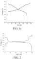
- the LMFP material has a certain length of a discharging plateau in high voltage range (the charging and discharging voltage plateau is 3.95V-4.0V as shown in FIG. 1a ), which is beneficial to reducing the risk of Li-Plating when the system is charged at a high rate in a high SOC state.
- the LFP material has a long charging and discharging plateau (the charging and discharging voltage plateau is about 3.2 V as shown in FIG. 1b ), which is beneficial to improving the high-power discharging performance in a low SOC state of the system.
- the capacity release of the ternary material over the entire voltage range is relatively even (as shown in 1c), and more prone to the capacity release in a high-voltage range. Therefore, the battery prepared by mixing the above three materials in a proper proportion has a charging and discharging plateau in both a high SOC state and a low SOC state (as shown in FIG. 2 ).
- a high SOC state LMFP and the ternary material can discharge cooperatively, the battery has a small polarization and can work at a large rate, the discharging power is large, but the actual discharging current borne by each material is small.
- the battery when the battery is charged at a high rate in a high SOC state, the three materials can be charged cooperatively, and the actual charging current borne by each material is small, so Li-Plating is unlikely to occur due to over charging.
- LFP and LMFP can be charged and discharged cooperatively, the battery has a small polarization, and the discharge power of the battery is large, which is helpful for the powered vehicle to reach a predetermined speed quickly when it is started.
- LMFP, LFP and ternary material are mixed in a proper proportion and used as the positive electrode active material; and the parameters ⁇ and ⁇ in are controlled in a certain range based on the specific capacity, efficiency and others of the positive and negative electrode active materials, such that the battery has both high average voltage and high specific capacity, the energy density is improved, the risk of Li-Plating when the battery is charged in a high SOC state is reduced, and the discharging power in a low SOC state is increased.
- ⁇ (M 1 ⁇ ⁇ 1 ⁇ A 1 +M 2 ⁇ ⁇ 2 ⁇ A 2 +M 3 ⁇ ⁇ 3 ⁇ A 3 ) ⁇ b ⁇ c/(a ⁇ A 3 ⁇ 1000), and it is satisfied that: 0.45 ⁇ 1.55, where a is the residual alkali content of the ternary material, b is the injection coefficient of the lithium ion battery, in g/Ah, and c is the theoretical residual water content in the electrolyte in assembled lithium ion battery; and a and c are in ppm.
- the parameter a can be obtained by testing the used ternary material before the lithium ion battery is assembled.
- the parameter b is a parameter that is definite when the battery is designed, and c is a theoretical value.
- the residual water content c in the electrolyte is usually between 200 ppm and 400 ppm.
- the injection coefficient b of is a ratio of the injected amount of the electrolyte in the battery to the designed discharge capacity of the battery. When the injection coefficient b is definite, and the capacity of the battery is definite, the mass of the electrolyte in the battery can be determined.
- a theoretical value (in g) of the water contained in the electrolyte can be known from c, and the amount of HF converted from water can be further determined.
- b is in the range of 2.9 g/Ah-3.8 g/Ah.
- the parameter ⁇ can represent the inhibition of HF in electrolyte in the battery.
- the ternary material can preferentially consume the residual water in the electrolyte of the battery and reduce the HF content in the electrolyte because of its good water absorption performance.
- the residual alkali content on the surface of the ternary material meets a certain relationship with the HF content in the electrolyte (that is, 0.45 ⁇ 1.55), the HF content in the electrolyte can be greatly reduced, thereby significantly reducing the dissolution of iron from the LFP material and the dissolution of iron and manganese from the LMFP material. This is beneficial to the structural stability of the two materials, thus improving the cycling performance and cycling life of the battery.
- ⁇ is in the range of 0.5 ⁇ 1.45.
- a 2 is 2-5 times A 1 . In this case, the discharging power and safety performance of the lithium ion battery under different SOC states can be guaranteed to be better. In some embodiments of the present disclosure, A 2 is 2.4-3.5 times A 1 .
- a 1 is in the range of 10%-25%. In some embodiments of the present disclosure, A 1 is in the range of 15%-25%. In some other embodiments of the present disclosure, A 1 is in the range of 15%-22%. In some embodiments of the present disclosure, A 2 is in the range of 45%-80%. In some embodiments of the present disclosure, A 2 is in the range of 45%-75%. In some other embodiments of the present disclosure, A 2 is in the range of 50%-75%. In some embodiments of the present disclosure, A 3 is in the range of 10%-40%. In some embodiments of the present disclosure, A 3 is in the range of 10%-30%. In some other embodiments of the present disclosure, A 3 is in the range of 10%-25%.
- the ratio (X/Y) of X to Y is in the range of 1.71-1.89. This can not only avoid Li-Plating on the negative electrode plate in the charging process, but also facilitate the exertion of the capacity of the positive electrode active material and the improvement of the energy density of the battery. In some embodiments of the present disclosure, X/Y is 1.73, 1.82 or 1.87.
- M is at least one of Mn, Al, Zr, Ti, Y, Sr and W.
- y meets 0.01 ⁇ y ⁇ 0.33, and z meets 0.01 ⁇ z ⁇ 0.33.
- x is in the range of 0.70 ⁇ x ⁇ 0.98.
- the ternary material can also be called “high-nickel ternary material", which has good water absorption, high specific capacity and good rate performance, and has H2-H3 phase transition and an obvious charging and discharging plateau around 4.1-4.15V, which is beneficial to the cooperative discharging of LMFP and the high-nickel ternary material.
- x is in the range of 0.80 ⁇ x ⁇ 0.90. In some embodiments of the present disclosure, x is in the range of 0.83 ⁇ x ⁇ 0.88.
- Nickel in the ternary material is alkaline, and tends to absorb moisture and carbon dioxide when exposed to air, which react with surface lithium to generate lithium hydroxide (LiOH) and lithium carbonate (LizCOs).
- the residual alkali content of the ternary material specifically refers to the percentage of the mass of LiOH and Li 2 CO 3 relative to the total mass of the ternary material determined before the battery is assembled.
- a is in the range of 500 ppm-1500 ppm.
- the molar amount of manganese accounts for 0.75-0.9 of the total molar amount of manganese and iron in the lithium manganese iron phosphate material. That is, the lithium manganese iron phosphate has a general formula of LiMn k Fe 1-k PO 4 , in which 0.75 ⁇ k ⁇ 0.9. In this case, the molar ratio of manganese element is relatively large, such that the lithium manganese iron phosphate material has a longer charging voltage plateau at 4.05-4.1 V, which is more conducive to reducing the risk of Li-Plating when the battery is charged at a large rate in a high SOC state.
- the particle size D50 of the ternary material is 4 ⁇ m-6 ⁇ m, for example, 4 ⁇ m-5 ⁇ m.
- the ternary material is a quasi-single crystal material, having a structural stability higher than that of the agglomerated ternary material.
- the particle size D50 of the lithium iron phosphate material is 0.8 ⁇ m-1.3 ⁇ m, for example, 0.8 ⁇ m-1.2 ⁇ m.
- the particle size D50 of the lithium manganese iron phosphate material ranges from 10 mm to 15 mm.
- the surface of the lithium iron phosphate or lithium iron phosphate material also has a carbon coating to improve the conductivity. Further, the carbon content in the lithium iron phosphate or lithium iron phosphate material is 0.8wt%-1.2wt%.
- the positive electrode material layer and the negative electrode material layer further include a conductive agent and a binder.
- the positive electrode material layer can be obtained by coating a positive electrode slurry containing the positive electrode active material, the conductive agent, the binder, and a solvent, and drying. When the positive electrode slurry is prepared, the binder and the solvent is mixed, and stirred fully; then the conductive agent is added and stirred; and then the positive electrode active material is added, stirred, and sieved.
- the added positive electrode active material can be directly a mixture of the above-mentioned LMFP, LFP and ternary material, or these three materials added in batches.
- the percentage by mass of the positive electrode active material in the positive electrode material layer is 95%-97%. In some embodiments of the present disclosure, the percentage by mass of the graphite in the negative electrode material layer is 95%-98%.
- the positive electrode active material allows the maximum compacted density of the positive electrode plate to fall in the range of 2.7 g/cm 3 -2.8 g/cm 3 .
- the conductive agent and binder are conventional choices in the battery field.
- the conductive agent can be, without limitation, at least one of carbon nanotubes, carbon fibers, carbon black (such as acetylene black, Cochin black), furnace black and graphene.
- the conductive agent includes all three types of the carbon nanotubes, carbon black and graphene, and the conductive agents of three dimensions can make the positive electrode material layer have better conductivity.
- the mass ratio of carbon nanotubes, carbon black and graphene can be 6: 5: 2.
- the binder can be one or more selected from polyvinylidene fluoride (PVDF), polytetrafluoroethylene (PTFE), polyvinyl alcohol (PVA), styrene-butadiene rubber (SBR), polyacrylonitrile (PAN), polyimide (PI), polyacrylic acid (PAA), polyacrylate, polyalkene (such as polyethylene, polypropylene, and polystyrene), sodium carboxymethyl cellulose (CMC) and sodium alginate.
- PVDF can be a copolymer obtained by copolymerization of vinylidene fluoride with an alkene compound containing a polar group including at least one of carboxyl group, epoxy group, hydroxyl group and sulfonic acid group. The existence of the polar group can enhance the peeling strength between the positive electrode material layer or the negative electrode material layer and the current collector.
- the positive electrode current collector and the negative electrode current collector can be independently selected from a metal foil or an alloy foil.
- the metal foil includes a copper, titanium, aluminum, platinum, iridium, ruthenium, nickel, tungsten, tantalum, gold or silver foil
- the alloy foil includes stainless steel, or an alloy of at least one element selected from copper, titanium, aluminum, platinum, iridium, ruthenium, nickel, tungsten, tantalum, gold and silver.
- the alloy foil is mainly composed of the above elements.
- the metal foil may further contain a doping element including, but not limited to, one or more of platinum, ruthenium, iron, cobalt, gold, copper, zinc, aluminum, magnesium, palladium, rhodium, silver and tungsten.
- the positive electrode current collector and the negative electrode current collector can be etched or roughened to form a secondary structure, to facilitate the effective contact with the electrode material layer.
- the positive electrode current collector is often an aluminum foil, and the negative electrode current collector is often a copper foil.
- the present disclosure further provides a powered vehicle including the lithium ion battery. Due to the use of the lithium ion battery, the powered vehicle can be rapidly fully charged when charged on a charging pile and can quickly reach a higher starting speed when started, and the battery has long battery life and high safety.
- the LMFP material used in the embodiments of the present disclosure is LiMn 0.8 Fe 0.2 PO 4 , having a particle size D50 of 10-15 ⁇ m, an initial charging specific capacity M 1 of 160 mAh/g, and initial efficiency ⁇ 1 of 96%.
- the LFP material used has a particle size D50 of 0.8-1.2 ⁇ m, an initial charging specific capacity M 2 of 162 mAh/g, and an initial efficiency ⁇ 2 of 99%.
- the ternary material is a high-nickel ternary quasi-single crystal material, having a general formula of LiNi 083 Co 0.12 Mn 0.05 , a particle size D50 of 4-5 ⁇ m, an initial charging specific capacity M 3 of 238 mAh/g, an initial efficiency ⁇ 3 of 86%, and a residual alkali content a of 700 ppm.
- the graphite has an initial discharging specific capacity M 4 of 355 mAh/g, and an initial efficiency ⁇ 4 of 95%.
- the injection coefficient b of the battery to be assembled is 3.1 g/Ah, and the theoretical value of residual water content c in the electrolyte after the battery is assembled is designed to be 200 ppm.
- the LMFP material, the LFP material, and the ternary material were mixed according to mixing proportions A 1 , A 2 , and A 3 provided in Table 1 respectively, to obtain the positive electrode active materials of various examples.
- the ratio of the coating amount X of the positive electrode active material on the positive electrode plate to the coating amount Y of graphite on the negative electrode plate was controlled according to Table 1.
- the parameters ⁇ , ⁇ , and ⁇ were determined according to the formulas above. Corresponding test parameters are summarized in Table 1.
- Preparation of positive electrode plate The organic solvent NMP and the binder PVDF were added into a blender, and stirred for 1 hr. Then a conductive agent (specifically a mixture of carbon nanotubes, carbon black and graphene at a mass ratio of 6:5:2), and stirred for 30 min. Then the positive electrode active material of each example or comparative example was added, stirred for 3 hrs, and sieved, to obtain the positive electrode slurry of each example and comparative example. The mixing ratio of the positive electrode active material, the conductive agent, the binder PVDF and the organic solvent NMP in the positive electrode slurry was 100:2:2:30.
- the positive electrode slurry of each example and comparative example were coated on two side surfaces of an aluminum foil, and baked at a high temperature to remove NMP, to form a positive electrode material layer on the aluminum foil.
- the positive electrode material layer was rolled and cut, to obtain a double-sided positive electrode plate with an areal density of 4.0 g/dm 2 of two side surfaces. According to the areal density and thickness of the double-sided electrode plate, the compacted density of the electrode plate was calculated. The results are summarized in Table 2.
- the positive electrode slurry of each example and comparative example were coated on one side surface of an aluminum foil, and baked at a high temperature to remove NMP, to form a positive electrode material layer on the aluminum foil.
- the system was rolled and cut, to obtain a single-sided positive electrode plate with an areal density of 2.0 g/dm 2 of one side surface.
- Preparation of negative electrode plate The graphite, the electrically conductive carbon black Supper P, the binder SBR, the binder CMC, and water were mixed at a mass ratio of 100: 1.0: 2.5: 1.1: 105, to obtain a negative electrode slurry.
- the negative electrode slurry was coated on two side surfaces of a copper foil, and baked at a high temperature to remove water, to form a negative electrode material layer.
- the system was rolled, and cut, to obtain a double-sided negative electrode plate with an areal density of 2.1 g/dm 2 and a compacted density of 1.60 g/cm 3 .
- the single-sided positive electrode plate of each example and comparative example, a metal lithium sheet as a negative electrode, a Celgard 2300 microporous membrane as a separator, and a 1.0 mol/L LiPF 6 solution in ethylene carbonate (EC): dimethyl carbonate (DMC) 1:1-5 (volume ratio) as an electrolyte, were assembled into a CR2025 button cell in a glove box.
- EC ethylene carbonate
- DMC dimethyl carbonate
- Test method for capacity retention rate after 2000 cycles at 45°C At 45°C, the full cell of each example and comparative example were charged to a voltage of 4.1 V at a constant current of 1C, and then charged at a constant voltage of 4.1 V, until the cutoff current was 0.05C. Then, the cell was discharged at a constant current of 1C until the voltage was 2.5 V. Following the above process, 2000 cycles of charging and discharging were performed. The ratio of discharging capacity of the battery in the 2000th cycle to the discharge capacity in the first cycle was calculated. The ratio was taken as the capacity retention rate after 2000 cycles.
- test methods for M 1 and ⁇ 1 of the LMFP material was as follows.
- a LMFP positive electrode plate (the positive electrode active material contains only LMFP) with an areal density of 2.0 g/dm 2 of one side surface and a compacted density of about 2.5 g/cm 3 was prepared as described above.
- the LMFP positive electrode plate, a metal lithium sheet, a separator, and an amount of an electrolyte were assembled into a CR2025 button cell in a glove box. The button cell was allowed to stand for about 4 hrs, so that the electrode plate was fully infiltrated in the electrolyte.
- the button cell was charged to a voltage of 4.3 V at a constant current of 0.1C and then to a cutoff current of 0.01C at a constant voltage of 4.3V, and then discharged to a voltage of 2.0 V at a constant current of 0.1C.
- the ratio of the discharging capacity to the charging capacity in the first cycle was recorded as the initial efficiency ⁇ 1
- the ratio of the charging capacity in the first cycle to the mass of the LMFP active material on the electrode plate was recorded as the initial charging specific capacity M 1 of the LMFP material.
- the test methods for M 2 and ⁇ 2 of the LFP material were as follows: A LFP positive electrode plate (the positive electrode active material contains only LFP) with an areal density of 2.0 g/dm 2 of one side surface and a compacted density of about 2.6g/cm 3 was prepared as described above. The LFP positive electrode plate, a metal lithium sheet, a separator, and an amount of an electrolyte were assembled into a CR2025 button cell in a glove box. The button cell was allowed to stand for about 4 hrs, so that the electrode plate was fully infiltrated in the electrolyte.
- the button cell was charged to a voltage of 3.8V at a constant current of 0.1C and then to a cutoff current of 0.01C at a constant voltage of 3.8V, and then discharged to a voltage of 2.0 V at a constant current of 0.1C.
- the ratio of the discharging capacity to the charging capacity in the first cycle was recorded as the initial efficiency ⁇ 2
- the ratio of the charging capacity in the first cycle to the mass of the LFP active material on the electrode plate was recorded as the initial charging specific capacity M 2 of the LFP material.
- the test methods for M 3 and ⁇ 3 of the ternary material were as follows: A ternary material positive electrode plate with an areal density of 2.0 g/dm 2 of one side surface and a compacted density of about 3.5 g/cm 3 were prepared as described above.
- the positive electrode active material on the positive electrode plate contains only the ternary material LiNi 083 Co 0.12 Mn 0.05 .
- the ternary material positive electrode plate, a lithium sheet, a separator, and an amount of an electrolyte were assembled into a CR2025 button cell in a glove box. The button cell was allowed to stand for about 4 hrs, so that the electrode plate was fully infiltrated in the electrolyte.
- the button cell was charged to a voltage of 4.3 V at a constant current of 0.1C and then to a cutoff current of 0.01C at a constant voltage of 4.3V, and then discharged to a voltage of 3.0V at a constant current of 0.1C.
- the ratio of the discharging capacity to the charging capacity in the first cycle was recorded as the initial efficiency ⁇ 3
- the ratio of the charging capacity in the first cycle to the mass of the active material on the electrode plate was recorded as the initial charging specific capacity M 3 of the high-nickel ternary material.
- the test methods for M 4 and ⁇ 4 of graphite were as follows: A graphite electrode plate with an areal density of 1.05 g/dm 2 of one side surface and a compacted density of about 1.60 g/cm 3 was prepared as described above. The graphite electrode plate, a lithium sheet, a separator, and an amount of an electrolyte were assembled into a CR2025 button cell in a glove box. The button cell was allowed to stand for about 4 hrs, so that the electrode plate was fully infiltrated in the electrolyte. The button cell was (1) discharged to 0.005 V at a constant current of 0.1C; (2) discharged to 0.001 V at a constant current of 0.09C, 0.08C...
- Comparative Example 2 where LMFP is mixed with the ternary material and no LFP is involved, the discharging power in a low SOC state is low and only 300 W/g. The content of the ternary material is too high, and the problems in Comparative Example 1 occur. Moreover, the cycling performance of LMFP is worse than that of the LFP material, and the capacity retention rate of the full cell in Comparative Example 2 after 2000 cycles at 45°C is lower than that of the full cell in Comparative Example 1, and is only 70%.
- Comparative example 3 LMFP and LFP materials are mixed, and no ternary material is involved. Due to the lack of the ternary material to inhibit the existence of HF in the electrolyte and further inhibit the dissolution of Mn and Fe, the cycling performance of the battery in Comparative Example 3 is the worst, and the capacity retention rate of the battery after 2000 cycles at 45°C is as low as 60%.
- Comparative example 4 although a mixture of three positive electrode active materials is used, the mixing ratio is not within the range of 1.03 ⁇ 1.15 and 0.55 ⁇ 1.5 required in the present disclosure.
- the battery in Comparative Example 4 has a low charging power in a high SOC state and a low discharging power in a low SOC state. Due to the excessive ternary material added, the safety performance and cycling performance decrease to varying degrees.
- the discharge power of the battery in a low SOC state and the charge power in a high SOC state are large.
- the discharge power in a low SOC state can be up to 1400 W/g or higher, and the charge power in a high SOC can be up to 600 W/g or higher.
- the compacted density of the positive electrode plate is high, the structural stability of the positive electrode material is high, and the battery has good cycling performance and safety.
- ⁇ is in the range of 0.45-1.55, the comprehensive performance of the battery is more excellent.
Landscapes
- Chemical & Material Sciences (AREA)
- Chemical Kinetics & Catalysis (AREA)
- Electrochemistry (AREA)
- General Chemical & Material Sciences (AREA)
- Inorganic Chemistry (AREA)
- Engineering & Computer Science (AREA)
- Materials Engineering (AREA)
- Composite Materials (AREA)
- Manufacturing & Machinery (AREA)
- Crystallography & Structural Chemistry (AREA)
- Battery Electrode And Active Subsutance (AREA)
- Secondary Cells (AREA)
Applications Claiming Priority (2)
| Application Number | Priority Date | Filing Date | Title |
|---|---|---|---|
| CN202110320984.1A CN115132975B (zh) | 2021-03-25 | 2021-03-25 | 一种锂离子电池及动力车辆 |
| PCT/CN2022/082943 WO2022199681A1 (zh) | 2021-03-25 | 2022-03-25 | 锂离子电池及动力车辆 |
Publications (2)
| Publication Number | Publication Date |
|---|---|
| EP4300633A1 true EP4300633A1 (de) | 2024-01-03 |
| EP4300633A4 EP4300633A4 (de) | 2025-07-09 |
Family
ID=83374198
Family Applications (1)
| Application Number | Title | Priority Date | Filing Date |
|---|---|---|---|
| EP22774335.8A Pending EP4300633A4 (de) | 2021-03-25 | 2022-03-25 | Lithium-ionen-batterie und kraftfahrzeug |
Country Status (7)
| Country | Link |
|---|---|
| US (1) | US20240021793A1 (de) |
| EP (1) | EP4300633A4 (de) |
| JP (1) | JP7698731B2 (de) |
| KR (1) | KR20230150863A (de) |
| CN (1) | CN115132975B (de) |
| CA (1) | CA3213251A1 (de) |
| WO (1) | WO2022199681A1 (de) |
Cited By (1)
| Publication number | Priority date | Publication date | Assignee | Title |
|---|---|---|---|---|
| EP4224574A4 (de) * | 2020-10-28 | 2025-04-23 | BYD Company Limited | Lithiumionenbatterie |
Families Citing this family (9)
| Publication number | Priority date | Publication date | Assignee | Title |
|---|---|---|---|---|
| CN115742857B (zh) * | 2022-12-05 | 2025-07-22 | 章鱼博士智能技术(上海)有限公司 | 电池混联系统的均衡方法、装置、存储介质及电子设备 |
| CN115832224B (zh) * | 2023-01-05 | 2023-12-22 | 厦门海辰储能科技股份有限公司 | 正极片及其制备方法、电极组件、储能设备及用电设备 |
| CN116314586A (zh) * | 2023-03-07 | 2023-06-23 | 上海兰钧新能源科技有限公司 | 一种二次电池 |
| CN116338472A (zh) * | 2023-04-19 | 2023-06-27 | 惠州亿纬锂能股份有限公司 | 一种电池剩余电量估算方法及系统 |
| CN118231600B (zh) * | 2023-07-31 | 2025-10-17 | 比亚迪股份有限公司 | 一种锂电池和动力车辆 |
| CN117577978B (zh) * | 2024-01-19 | 2024-04-02 | 四川新能源汽车创新中心有限公司 | 一种电池热稳定条件的确定方法和电池储存方法 |
| CN119315140B (zh) * | 2024-09-24 | 2025-11-04 | 湖北亿纬动力有限公司 | 一种锂电池化成工艺 |
| CN119153825B (zh) * | 2024-11-18 | 2025-03-21 | 中创新航科技集团股份有限公司 | 二次电池和用电装置 |
| CN119833770A (zh) * | 2024-12-30 | 2025-04-15 | 远景动力技术(湖北)有限公司 | 电化学装置和用电装置 |
Family Cites Families (12)
| Publication number | Priority date | Publication date | Assignee | Title |
|---|---|---|---|---|
| JP2007317539A (ja) | 2006-05-26 | 2007-12-06 | Sony Corp | 正極材料および電池 |
| JP5359490B2 (ja) | 2009-04-14 | 2013-12-04 | 株式会社豊田中央研究所 | リチウムイオン二次電池 |
| CN101572327A (zh) * | 2009-06-11 | 2009-11-04 | 天津大学 | 石墨烯为负极材料的锂离子电池 |
| JP2014192142A (ja) * | 2013-03-28 | 2014-10-06 | Shin Kobe Electric Mach Co Ltd | リチウムイオン電池 |
| CN103647040A (zh) * | 2013-11-12 | 2014-03-19 | 江苏华东锂电技术研究院有限公司 | 电极浆料、负电极及应用该负电极的锂离子电池 |
| CN104577194A (zh) * | 2015-01-21 | 2015-04-29 | 桐乡市众胜能源科技有限公司 | 高能量磷酸铁锂电池 |
| CN105449269B (zh) * | 2016-01-08 | 2018-07-24 | 深圳市沃特玛电池有限公司 | 一种锂离子电池 |
| CN105702919B (zh) * | 2016-04-06 | 2018-10-02 | 中国科学院青岛生物能源与过程研究所 | 一种包含界面稳定聚合物材料的锂电池电极制备方法及在固态锂电池中的应用 |
| CN107528050A (zh) * | 2017-08-08 | 2017-12-29 | 上海华普汽车有限公司 | 锂离子电池正极活性物质、正极材料、正极材料浆料、正极片、其制备方法和锂离子电池 |
| KR102305491B1 (ko) * | 2018-12-05 | 2021-09-27 | 도레이 카부시키가이샤 | 리튬 이온 이차 전지용 정극 전극, 리튬 이온 이차 전지용 전극 페이스트, 리튬 이온 이차 전지 |
| US11804601B2 (en) | 2019-09-12 | 2023-10-31 | Saft America | Cathode materials for lithium ion batteries |
| CN116111085B (zh) * | 2020-09-14 | 2026-03-13 | 天津容百斯科兰德科技有限公司 | 一种锂离子电池 |
-
2021
- 2021-03-25 CN CN202110320984.1A patent/CN115132975B/zh active Active
-
2022
- 2022-03-25 CA CA3213251A patent/CA3213251A1/en active Pending
- 2022-03-25 KR KR1020237033303A patent/KR20230150863A/ko active Pending
- 2022-03-25 JP JP2023558576A patent/JP7698731B2/ja active Active
- 2022-03-25 WO PCT/CN2022/082943 patent/WO2022199681A1/zh not_active Ceased
- 2022-03-25 EP EP22774335.8A patent/EP4300633A4/de active Pending
-
2023
- 2023-09-25 US US18/473,996 patent/US20240021793A1/en active Pending
Cited By (1)
| Publication number | Priority date | Publication date | Assignee | Title |
|---|---|---|---|---|
| EP4224574A4 (de) * | 2020-10-28 | 2025-04-23 | BYD Company Limited | Lithiumionenbatterie |
Also Published As
| Publication number | Publication date |
|---|---|
| JP7698731B2 (ja) | 2025-06-25 |
| US20240021793A1 (en) | 2024-01-18 |
| JP2024511135A (ja) | 2024-03-12 |
| CN115132975A (zh) | 2022-09-30 |
| CA3213251A1 (en) | 2022-09-29 |
| WO2022199681A1 (zh) | 2022-09-29 |
| CN115132975B (zh) | 2024-09-10 |
| KR20230150863A (ko) | 2023-10-31 |
| EP4300633A4 (de) | 2025-07-09 |
Similar Documents
| Publication | Publication Date | Title |
|---|---|---|
| EP4300633A1 (de) | Lithium-ionen-batterie und kraftfahrzeug | |
| EP3663265B1 (de) | Positivelektrodenaktivmaterial für eine lithiumsekundärbatterie und damit versehene lithiumsekundärbatterie | |
| US11984589B2 (en) | Positive-electrode plate and manufacturing method thereof, lithium-ion secondary battery, battery module, battery pack, and apparatus | |
| US11196041B2 (en) | Positive electrode plate and lithium-ion secondary battery | |
| EP4220754A1 (de) | Negativelektrodenplatte aus lithiummetall, elektrochemische vorrichtung und elektronische vorrichtung | |
| EP4220759A1 (de) | Negativelektrodenplatte aus lithiummetall, elektrochemische vorrichtung und elektronische vorrichtung | |
| CN108832075B (zh) | 锂离子电池 | |
| CN110165284B (zh) | 锂离子二次电池 | |
| CN115020678B (zh) | 正极活性材料、电化学装置和电子设备 | |
| US20230335713A1 (en) | Positive electrode material, preparation method therefor and lithium ion battery | |
| EP3435454B1 (de) | Lithium-ionen-batterie und positivaktivmaterial dafür | |
| CN111422919B (zh) | 四元正极材料及其制备方法、正极、电池 | |
| US11990616B2 (en) | Positive electrode active material for lithium secondary battery and lithium secondary battery including the same | |
| CN114430039B (zh) | 一种锂离子电池及动力车辆 | |
| JPH09237631A (ja) | リチウム二次電池用正極活物質とその製造方法及びリチウム二次電池 | |
| JP2018190582A (ja) | リチウムイオン二次電池の製造方法 | |
| WO2005104273A1 (ja) | リチウムイオン二次電池 | |
| WO2024244170A1 (zh) | 锂二次电池和用电装置 | |
| CN115360323B (zh) | 一种锂离子电池 | |
| US20230268515A1 (en) | Lithium ion battery | |
| US20070054191A1 (en) | Non- aqueous electrolyte secondary battery | |
| CN116960360A (zh) | 一种安全涂层及其制备方法、极片以及二次电池 | |
| CN116759535B (zh) | 电化学装置以及电子设备 | |
| CN119864364A (zh) | 一种锂电池负极极片及其制备方法与应用、锂离子二次电池 | |
| CN121123176A (zh) | 一种正极片及其制备方法、电池、电池组及用电设备 |
Legal Events
| Date | Code | Title | Description |
|---|---|---|---|
| STAA | Information on the status of an ep patent application or granted ep patent |
Free format text: STATUS: THE INTERNATIONAL PUBLICATION HAS BEEN MADE |
|
| PUAI | Public reference made under article 153(3) epc to a published international application that has entered the european phase |
Free format text: ORIGINAL CODE: 0009012 |
|
| STAA | Information on the status of an ep patent application or granted ep patent |
Free format text: STATUS: REQUEST FOR EXAMINATION WAS MADE |
|
| 17P | Request for examination filed |
Effective date: 20230928 |
|
| AK | Designated contracting states |
Kind code of ref document: A1 Designated state(s): AL AT BE BG CH CY CZ DE DK EE ES FI FR GB GR HR HU IE IS IT LI LT LU LV MC MK MT NL NO PL PT RO RS SE SI SK SM TR |
|
| DAV | Request for validation of the european patent (deleted) | ||
| DAX | Request for extension of the european patent (deleted) | ||
| A4 | Supplementary search report drawn up and despatched |
Effective date: 20250606 |
|
| RIC1 | Information provided on ipc code assigned before grant |
Ipc: H01M 10/44 20060101ALI20250602BHEP Ipc: H01M 4/02 20060101ALI20250602BHEP Ipc: H01M 10/42 20060101ALI20250602BHEP Ipc: H01M 4/131 20100101ALI20250602BHEP Ipc: H01M 4/133 20100101ALI20250602BHEP Ipc: H01M 4/136 20100101ALI20250602BHEP Ipc: H01M 4/36 20060101ALI20250602BHEP Ipc: H01M 4/485 20100101ALI20250602BHEP Ipc: H01M 4/587 20100101ALI20250602BHEP Ipc: H01M 10/0525 20100101ALI20250602BHEP Ipc: H01M 4/505 20100101ALI20250602BHEP Ipc: H01M 4/525 20100101ALI20250602BHEP Ipc: H01M 4/58 20100101AFI20250602BHEP |