EP4300647A1 - Ensemble électrode et élément de batterie le comprenant - Google Patents
Ensemble électrode et élément de batterie le comprenant Download PDFInfo
- Publication number
- EP4300647A1 EP4300647A1 EP22878776.8A EP22878776A EP4300647A1 EP 4300647 A1 EP4300647 A1 EP 4300647A1 EP 22878776 A EP22878776 A EP 22878776A EP 4300647 A1 EP4300647 A1 EP 4300647A1
- Authority
- EP
- European Patent Office
- Prior art keywords
- electrode
- electrode assembly
- separator sheet
- side surfaces
- separator
- Prior art date
- Legal status (The legal status is an assumption and is not a legal conclusion. Google has not performed a legal analysis and makes no representation as to the accuracy of the status listed.)
- Pending
Links
Images


Classifications
-
- H—ELECTRICITY
- H01—ELECTRIC ELEMENTS
- H01M—PROCESSES OR MEANS, e.g. BATTERIES, FOR THE DIRECT CONVERSION OF CHEMICAL ENERGY INTO ELECTRICAL ENERGY
- H01M10/00—Secondary cells; Manufacture thereof
- H01M10/04—Construction or manufacture in general
- H01M10/0459—Cells or batteries with folded separator between plate-like electrodes
-
- H—ELECTRICITY
- H01—ELECTRIC ELEMENTS
- H01M—PROCESSES OR MEANS, e.g. BATTERIES, FOR THE DIRECT CONVERSION OF CHEMICAL ENERGY INTO ELECTRICAL ENERGY
- H01M10/00—Secondary cells; Manufacture thereof
- H01M10/05—Accumulators with non-aqueous electrolyte
- H01M10/058—Construction or manufacture
- H01M10/0583—Construction or manufacture of accumulators with folded construction elements except wound ones, i.e. folded positive or negative electrodes or separators, e.g. with "Z"-shaped electrodes or separators
-
- H—ELECTRICITY
- H01—ELECTRIC ELEMENTS
- H01M—PROCESSES OR MEANS, e.g. BATTERIES, FOR THE DIRECT CONVERSION OF CHEMICAL ENERGY INTO ELECTRICAL ENERGY
- H01M50/00—Constructional details or processes of manufacture of the non-active parts of electrochemical cells other than fuel cells, e.g. hybrid cells
- H01M50/40—Separators; Membranes; Diaphragms; Spacing elements inside cells
- H01M50/463—Separators, membranes or diaphragms characterised by their shape
- H01M50/466—U-shaped, bag-shaped or folded
-
- Y—GENERAL TAGGING OF NEW TECHNOLOGICAL DEVELOPMENTS; GENERAL TAGGING OF CROSS-SECTIONAL TECHNOLOGIES SPANNING OVER SEVERAL SECTIONS OF THE IPC; TECHNICAL SUBJECTS COVERED BY FORMER USPC CROSS-REFERENCE ART COLLECTIONS [XRACs] AND DIGESTS
- Y02—TECHNOLOGIES OR APPLICATIONS FOR MITIGATION OR ADAPTATION AGAINST CLIMATE CHANGE
- Y02E—REDUCTION OF GREENHOUSE GAS [GHG] EMISSIONS, RELATED TO ENERGY GENERATION, TRANSMISSION OR DISTRIBUTION
- Y02E60/00—Enabling technologies; Technologies with a potential or indirect contribution to GHG emissions mitigation
- Y02E60/10—Energy storage using batteries
-
- Y—GENERAL TAGGING OF NEW TECHNOLOGICAL DEVELOPMENTS; GENERAL TAGGING OF CROSS-SECTIONAL TECHNOLOGIES SPANNING OVER SEVERAL SECTIONS OF THE IPC; TECHNICAL SUBJECTS COVERED BY FORMER USPC CROSS-REFERENCE ART COLLECTIONS [XRACs] AND DIGESTS
- Y02—TECHNOLOGIES OR APPLICATIONS FOR MITIGATION OR ADAPTATION AGAINST CLIMATE CHANGE
- Y02P—CLIMATE CHANGE MITIGATION TECHNOLOGIES IN THE PRODUCTION OR PROCESSING OF GOODS
- Y02P70/00—Climate change mitigation technologies in the production process for final industrial or consumer products
- Y02P70/50—Manufacturing or production processes characterised by the final manufactured product
Definitions
- the present disclosure relates to an electrode assembly and a battery cell including the same. More particularly, the present disclosure relates to an electrode assembly in which electrodes and separator sheets are alternately stacked in a Z-folding type, and a battery cell including the same, and to an electrode assembly which prevents the electrode from being separated from a prescribed position and also has improved stiffness even though the adhesive strength of the separator sheet itself is low, and a battery cell including the same.
- secondary batteries include nickel-cadmium batteries, nickel-hydrogen batteries, lithium-ion batteries, lithium-ion polymer batteries, and the like.
- Such secondary batteries are applied and used not only to small-sized products such as digital cameras, P-DVD, MP3P, cellular phones, PDA, portable game devices, power tools and E-bikes, but also to large-sized products demanding high output such as electric and hybrid vehicles, and a power storage device for storing surplus generated power or new renewable energy and a backup power storage device.
- the electrode active material slurry is applied to a cathode current collector and an anode current collector to manufacture a cathode and an anode, which are stacked on both sides of the separator, thereby forming an electrode assembly having a predetermined shape. Then, the electrode assembly is housed in a battery case, and the electrolytic solution is injected and then sealed.
- Electrode assemblies are classified into various types. For example, there may be mentioned a simple stack type in which cathodes, separators, and anodes simply cross with each other and they are continuously stacked without manufacturing a unit cell, a lamination & stack type (L&S, lamination & stack type) in which unit cells are first manufactured using cathodes, separators, and anodes, and then these unit cells are stacked, a stack & folding type (S&F, stack & folding type) in which a plurality of unit cells are spaced apart and attached to one surface of a separator sheet having a long length, and the separator sheet is repeatedly folded in the same direction from one end, a Z-folding type in which a plurality of electrodes or unit cells are alternately attached to one surface and the other surface of a separator sheet whose length is long on one side, and the method of folding the separator sheet in a specific direction from one end and then folding it in the opposite direction are alternately repeated, and the like.
- L&S la
- an electrode assembly in which electrodes and separator sheets are alternately stacked in a Z-folding type, wherein the electrode includes a first electrode and a second electrode, wherein the separator sheet has a zigzag shape formed by being folded at least twice, wherein a length of the second electrode is smaller than a length of the first electrode, and wherein an adhesive member is located between either one of both side surfaces of the electrode assembly and the second electrode.
- the adhesive member may be located between a separator sheet which comes into contact with an upper surface of the second electrode and a separator sheet which comes into contact with a lower surface of the second electrode, and the adhesive member may be located between a side surface opposite to the side surface wrapped by the separator sheet among both side surfaces of the second electrode, and an outer side surface of the electrode assembly.
- the first electrode and the second electrode may be aligned so that the side surface opposite to the side surface wrapped by the separator sheet among both side surfaces of the first electrode, and the side surface wrapped by the separator sheet among both side surfaces of the second electrode may be biased to one side surface among the outer side surfaces of the electrode assembly.
- One side surface facing one end of the second electrode among both side surfaces of the adhesive member may be spaced apart from the second electrode.
- the side surface opposite to the side surface facing one end of the second electrode among both side surfaces of the adhesive member may be arranged side by side with the outer side surface of the electrode assembly.
- the side surface wrapped by the separator sheet among both side surfaces of the second electrode may come into contact with the separator sheet, and the side surface wrapped by the separator sheet among both side surfaces of the first electrode may come into contact with the separator sheet.
- a side surface opposite to the side surface wrapped the separator sheet among both side surfaces of the first electrode may be located on the same vertical line as the outer side surface of the electrode assembly.
- An adhesive strength between the electrode and the separator sheet may be 0 gf/mm or more and 0.05 gf/mm or less.
- One end of the separator sheet may extend along the outer surface of the electrode assembly.
- One end of the separator sheet may wrap around the entire outer surface of the electrode assembly.
- the electrode assembly may further comprise a wrapping member that wraps the outer surface of the electrode assembly.
- the wrapping member includes a first wrapping member and a second wrapping member, the first wrapping member wraps around a portion of the outer surface of the electrode assembly where the side surface opposite to the side surface wrapped by the separator sheet among both side surfaces of the first electrode is located, and the second wrapping member wraps around a portion of the outer surface of the electrode assembly where the side surface opposite to one side surface facing one end of the second electrode among both side surfaces of the adhesive member is located.
- the first wrapping member extends along one of the upper surface and the lower surface of the electrode assembly, and the second wrapping member extends along the other of the upper surface and the lower surface of the electrode assembly.
- the wrapping member may be made of at least one of a hot-melt film and an adhesive tape.
- a battery cell comprising the above-mentioned electrode assembly.
- the present disclosure provides an electrode assembly in which electrodes and separator sheets are alternately stacked in a Z-folding type, and an adhesive member is located between the electrode located between the separator sheets and the outer surface of the electrode assembly, so that the electrode assembly prevents the electrodes from being separated from a prescribed position, and has improved stiffness even if the adhesive strength of the separator sheet itself is low, and a battery cell comprising the same.
- planar it means when a target portion is viewed from the upper side
- cross-sectional it means when a target portion is viewed from the side of a cross section cut vertically.
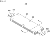
- Fig. 1 is a diagram showing a final electrode assembly according to one embodiment of the present disclosure.
- Fig. 2 is a cross-sectional view of the electrode assembly taken along the A-A' axis of Fig. 1 .
- an electrode assembly 100 may mean a structure in which a fixing tape 300 is attached to the outer surface of the electrode assembly 200. Accordingly, the final electrode assembly 100 can maintain a stacked alignment state between a first electrode 210, a second electrode 220, and a separator sheet 230 included in an electrode assembly 200.
- the present disclosure is not limited thereto, and the fixing tape 300 is omitted from the final electrode assembly 100 or is replaced with another member, thereby capable of maintaining the stacked alignment state between the first electrode 210, the second electrode 220 and the separator sheet 230.
- the final electrode assembly 100 may include a plurality of first electrodes 210 included in the electrode assembly 200 and an electrode lead 400 to which electrode tabs extending from the plurality of second electrodes 220 are joined.
- the electrode leads 400 may extend to both ends of the electrode assembly 200, respectively, and the electrode lead 400 may be divided into a cathode lead or an anode lead according to polarities of the first electrode 210 and the second electrode 220.
- the position of the electrode lead 400 is not limited thereto, and differently from Fig. 1 , it may extend together with one end of the electrode assembly 200.
- the final electrode assembly 100 may include a lead film 500 located in upper and lower parts of the electrode lead 400.
- the lead film 500 can be sealed by a sealing part (not shown) along with the outer periphery of the battery case (not shown).
- the electrode assembly 200 may be an electrode assembly in which electrodes 210 and 220 and separator sheets 230 are alternately stacked.
- the electrodes 210 and 220 may include a first electrode 210 and a second electrode 220.
- the first electrode 210 and the second electrode 220 may include electrode active materials having different polarities. That is, the first electrode 210 and the second electrode 220 may be electrodes having different polarities.
- the second electrode 220 may be an anode. In another example, if the first electrode 210 is an anode, the second electrode 220 may be a cathode.
- the length of the second electrode 220 may be smaller than the length of the first electrode 210.
- the length of the first electrode 210 may be larger than the length of the second electrode 220.
- the first electrode 210 and the second electrode 220 have different lengths along the first longitudinal direction L1, and thus, there may be a length difference between the first electrode 210 and the second electrode 220. Accordingly, a tolerance d may be formed between the second electrode 220 and the outer surface of the electrode assembly 200.
- the first longitudinal direction L1 may be a height direction or a length direction of the electrode assembly 200.
- the separator sheet 230 may have a zigzag shape formed by being folded at least twice. More specifically, as shown in Fig. 2 , the separator sheet 230 may be folded in a direction covering the first electrode 210 in a state in which the first electrode 210 is stacked. Also, in a state where the second electrode 220 is stacked on the separator sheet 230 covering the first electrode 210, it may be folded in a direction to cover the second electrode 220. Thereafter, in a state in which the first electrode 210 is stacked on the separator sheet 230 covering the second electrode 220, it may be folded in a direction to cover the first electrode 210. That is, the electrode assembly 200 can be formed by repeatedly performing stacking of the first electrode 210 or the second electrode 220 and folding of the separator sheet 230.
- the first electrode 210 and the second electrode 220 may be aligned so that the side surface opposite to the side surface wrapped by the separator sheet 230 among both side surfaces of the first electrode 210, and the side surface wrapped by the separator sheet 230 among both side surfaces of the second electrode 220 are biased to one side surface among the outer side surfaces of the electrode assembly 200.
- one end of the first electrode 210 and one end of the second electrode 220 may be aligned so as to be biased to one side surface of the electrode assembly 200. That is, in the electrode assembly 200 according to the present embodiment, the first electrode 210 and the second electrode 220 may not be aligned on the basis of the center of the electrode assembly 200, but may be aligned on the basis of one side surface of the electrode assembly 200.
- the area of the adhesive member 250 located between the second electrode 220 and the outer surface of the electrode assembly 200, which will be described later, may be larger.
- the side surface wrapped by the separator sheet 230 among both side surfaces of the second electrode 220 comes into contact with the separator sheet 230, and the side surface wrapped by the separator sheet among both side surfaces of the first electrode 210 may come into contact with the separator sheet 230.
- the separator sheet comes into contact with the first electrode 210 or the first electrode 220 may mean that the separator sheet 230 extends along the side surface of the first electrode 210 or the second electrode 220, or the separator sheet 230 wraps around the side surface of the first electrode 210 or the second electrode 220.
- a side surface opposite to the side surface wrapped by the separator sheet 230 among both side surfaces of the first electrode 210 may be located on the same vertical line as the outer side surface of the electrode assembly 200.
- the side surface opposite to the side surface wrapped by the separator sheet 230 among both side surfaces of the first electrode 210 may protrude toward the outer side surface of the electrode assembly 200 or may not be recessed.
- the adhesive member 250 is located between the second electrode 220 and the outer surface of the electrode assembly 200.
- the adhesive member 250 may be located within a tolerance d between the second electrode 220 and the outer surface of the electrode assembly 200. More specifically, the adhesive member 250 may be located between the separator sheet 230 which comes into contact with the upper surface of the second electrode 220 and the separator sheet 230 which comes into contact with the lower surface of the second electrode 220.
- the adhesive member 250 may be located between the side surface opposite to the side surface wrapped by the separator sheet 230 among both side surfaces of the second electrode 220 and the outer side surface of the electrode assembly 200.
- the adhesive member 250 is located in a space formed between the second electrode 220 and the outer surface of the electrode assembly 200, and thus has a structure that improves space efficiency and supplements the adhesive strength between the electrodes 210 and 220 and the separator 230, which can thus improve the stiffness of the electrode assembly 200.
- one side surface facing the second electrode 220 and one end thereof among both side surfaces of the adhesive member 250 may be spaced apart from the second electrode 220. In other words, a side surface adjacent to the second electrode 220 among both side surfaces of the adhesive member 250 may not come into contact with the second electrode 220.
- the adhesive member 250 does not come into contact with the second electrode 220, which can thus prevent an adhesive material included in the adhesive member 250 from interfering with the movement path of lithium ions formed between the first electrode 210 and the second electrode 220.
- the second electrode 220 may be a cathode, and the movement of lithium ions can be determined by the position of the cathode, which is generally smaller in size than the anode.
- the separation distance s between one end of the second electrode 220 and one side surface of the adhesive member 250 facing each other may be at least 0.5 mm or more, preferably 0.6 mm or more, and more preferably 1 mm or more.
- the line width of the adhesive applied by a dispenser is about 0.4 to 0.6 mm level.
- the adhesive may be applied without the adhesive member 250 interfering with the cathode side.
- the adhesive since the adhesive may be a contaminant, it is necessary to avoid applying too much.
- a side surface opposite to one side facing one end of the second electrode 220 among both side surfaces of the adhesive member 250 may be aligned side by side with the outer side surface of the electrode assembly 200.
- a side surface opposite to one side surface facing one end of the second electrode 220 among both side surfaces of the adhesive member 250 may protrude or may not be recessed on the basis of the outer surface of the electrode assembly 200.
- the adhesive member 250 may be made of an adhesive material containing one or more components selected from the group consisting of olefins, acrylates, urethanes, esters, amides, vinyl acetates, and rubber-based polymers.
- the present disclosure is not limited thereto, and any material capable of adhering between the electrodes 210 and 220 and the separator sheet 230 can be included in the present embodiment.
- the adhesive member 250 is uniformly applied to the tolerance d formed between the second electrode 220 and the outer surface of the electrode assembly 200.
- the application amount of the adhesive may be excessively large. In this case, the adhesive may flow to the outside of the separator sheet 230 and contaminate other parts, and when the secondary battery is manufactured, the function of generating power may not be smooth.
- the electrodes 210 and 220 are still not fixed to the separator sheet 230 while the cell is moving, and can be separated from a prescribed position. That is, it may be desirable that the interval of the area where the adhesive is applied is not excessively wide.
- the adhesive member 250 may be preferably applied by a spot application method of applying in a dot form or a line application method of applying in a line form to the tolerance d formed between the second electrode 220 and the outer surface of the electrode assembly 200.
- the diameter of a dot of a spot application method or the width of a line of a line application method may be 100um or more and 800um or less.
- the diameter of the dot of the spot application method or the width of the line of the line application method is not limited to the above range, and can be adjusted to have a diameter or width of an appropriate size as needed.
- the spot application or line application of the adhesive member 250 may be performed by a pneumatic method or a piezoelectric method.
- the present disclosure is not limited thereto, and any method capable of applying an adhesive onto a localized area can be included in the present embodiment.
- the electrode assembly 200 of the present embodiment has an adhesive member 250 formed between the second electrode 220 and the outer surface of the electrode assembly 200 even if the adhesive strength between the electrodes 210 and 220 and the separator sheet 230 changes depending on the material of the separator sheet 230, thereby capable of maintaining the stiffness of the electrode assembly while preventing the electrodes 210 and 220 from being separated from a prescribed position.
- the separator sheet 230 may be an inexpensive separator having relatively low adhesive strength.
- the separator sheet 230 may be a CCS (ceramic coated separator) separator.
- the separator sheet 230 is not limited thereto, and any separator having adhesive strength similar to that of the CCS separator can be included in the present embodiment.
- the adhesive strength between the electrodes 210 and 220 and the separator sheet 230 may be 0 gf/mm or more and 0.05 gf/mm or less. More specifically, the adhesive strength between the electrodes 210 and 220 and the separator sheet 230 may be 0 gf/mm or more and 0.045 gf/mm or less. In one example, the adhesive strength between the electrodes 210 and 220 and the separator sheet 230 may be 0 gf/mm or more and 0.04 gf/mm or less.
- an adhesive member 250 is formed between the second electrode 220 and the outer surface of the electrode assembly 200, thereby capable of preventing the electrodes 210 and 220 from being separated from a prescribed position and highly maintaining the stiffness of the electrode assembly, while supplementing the adhesive strength between the electrodes 210 and 220 and the separator sheet 230.
- the present embodiment has the advantage that the separator sheet 230 with relatively low adhesive strength can be used, and thus, economic efficiency improves as costs are reduced.
- the present embodiment does not need to perform a laminating process through the adhesive member 250 as in a conventional case, so that the defect rate in the process caused by high heat and pressure can be reduced. Further, since the laminator can be removed, the volume of the manufacturing device can be reduced and the manufacturing process can be simplified.
- Figs. 3 and 4 are cross-sectional views of an electrode assembly according to another embodiment of the present disclosure.
- the electrode assemblies 201 and 202 may be described in the same way as the electrode assembly 200 described above, and only parts different from the electrode assembly 200 will be described below.
- one end of the separator sheet 230 may extend along the outer surface of the electrode assembly 201. More specifically, one end of the separator sheet 230 may wrap around the entire outer surface of the electrode assembly 201. That is, one end of the separator sheet 230 may wrap around both side surfaces and upper and lower surfaces of the electrode assembly 201.
- the end of the separator sheet 230 wrapping around the outer surface of the electrode assembly 201 may be the end of the separator sheet 230 closest to the bottom surface.
- the end of the separator sheet 230 wrapping around the outer surface of the electrode assembly 201 may be the end of the separator sheet 230 adjacent to the upper end of the electrode assembly 201.
- the electrode assembly 201 can prevent the first electrode 210 from protruding to the outside by wrapping the separator sheet 230 around the outer surface of the electrode assembly 201.
- the separator sheet 230 wrapping around the outer surface of the electrode assembly 201 can further improve the stiffness of the electrode assembly 201 and effectively prevent the separator sheet 230 from being folded.
- the present embodiment can improve cost reduction and economic efficiency from the viewpoint of requiring no separate member.
- the electrode assembly 202 may further include a wrapping member 270 wrapping around an outer surface of the electrode assembly 202.
- the wrapping member 270 includes a first wrapping member and a second wrapping member.
- the first wrapping member may wrap around a portion of the outer surface of the electrode assembly 202 where the side surface opposite to the side surface wrapped by the separator sheet 230 among both side surfaces of the first electrode 210 is located.
- the second wrapping member may wrap around a portion of the outer surface of the electrode assembly 202 where the side surface opposite to one side surface facing one end of the second electrode 220 among both side surfaces of the adhesive member 250 is located. That is, the first wrapping member may wrap around one side surface of the electrode assembly 202, and the second wrapping member may wrap around the other side surface of the electrode assembly 202.
- first wrapping member extends along one of the upper surface and the lower surface of the electrode assembly 202
- second wrapping member may extend along the other of the upper surface and the lower surface of the electrode assembly 202.
- one of the wrapping members 270 extends along one side surface of the electrode assembly 202, and may extend to the upper surface of the electrode assembly 202.
- the other of the wrapping member 270 extends along the other side surface of the electrode assembly 202, and may extend to the lower surface of the electrode assembly 202.
- the present disclosure is not limited thereto, and the first wrapping member and the second wrapping member may be integrated with each other.
- the wrapping member 270 may be a hot-melt film containing at least one component selected from the group consisting of olefins, acrylates, urethanes, esters, amides, vinyl acetates, and rubber-based polymers.
- the wrapping member 270 may be an adhesive tape.
- the present disclosure is not limited thereto, and any polymer material having elasticity and adhesive strength sufficient to wrap around the outer surface of the electrode assembly 202 can be included in the present embodiment.
- the electrode assembly 202 can allow the wrapping member 270 to wrap around the outer surface of the electrode assembly 201, thereby preventing the first electrode 210 from protruding to the outside.
- the wrapping member 270 wrapping around the outer surface of the electrode assembly 201 can further improve the stiffness of the electrode assembly 201 and effectively prevent the separator sheet 230 from being folded.
- Fig. 5 is a cross-sectional view of an electrode assembly according to a comparative example.
- the electrode assembly 20 according to the comparative example may be configured such that the first electrodes 21 and the second electrodes 22 are alternately stacked between separators 23.
- the end of the separator 23 may have a shape that protrudes outward on the basis of the outer surface of the electrode assembly 20. Accordingly, there is a problem that an end of the separator 23 may be folded during the process, and a short circuit occurs when the separator 23 shrinks at a high temperature.
- the electrode assemblies 200, 201 and 202 according to the present embodiment have the advantage that the adhesive member 250 can be formed between the second electrode 220 and the outer surface of the electrode assembly 200, thereby preventing the electrodes 210 and 220 from being separated from their prescribed positions and highly maintaining the stiffness of the electrode assembly, while being able to use the separator sheet 230 having a relatively low adhesive strength.
- a battery cell according to another embodiment of the present invention includes the electrode assembly described above.
- the battery cell may include a battery case (not shown) that houses the above-described electrode assemblies 200, 201 and 202 together with an electrolyte solution.
- the electrode assemblies 200, 201 and 202 may be made of the above-described final electrode assembly 100 and housed in the battery case (not shown).
- the battery case may be a laminated sheet including a resin layer and a metal layer. More specifically, the battery case (not shown) is made of a laminated sheet, and may be composed of an outer resin layer forming the outermost shell, a barrier metal layer preventing penetration of materials, and an inner resin layer for sealing.
- a cathode and an anode were alternately stacked in this order between separator sheets, and the separator sheets were folded at least twice to manufacture an electrode assembly having a zigzag shape.
- the separator sheet is a CCS (Ceramic Coated Separator) separator.
- the size of the electrode assembly is 510 mm*97 mm.
- An electrode assembly was manufactured in the same manner as in Comparative Example 1, except that in Comparative Example 1, the length of the cathode was less than the length of the anode, and an adhesive was applied between the cathode and the outer surface of the electrode assembly to form an adhesive member.
- Fig. 6 is a diagram showing an experimental example of measuring the stiffness of an electrode assembly. As shown in Fig. 6 , the center of the electrode assembly 200 was placed on a bar having a thickness of 50 mm, and then the bending degree (L) of the electrode assembly 200 was measured based on the upper end of the bar. The results are shown in Table 1 below. [Table 1] Comparative Example Example Bending degree of the electrode assembly (L) 100cm 50cm
Landscapes
- Engineering & Computer Science (AREA)
- Manufacturing & Machinery (AREA)
- Chemical & Material Sciences (AREA)
- Chemical Kinetics & Catalysis (AREA)
- Electrochemistry (AREA)
- General Chemical & Material Sciences (AREA)
- Secondary Cells (AREA)
- Cell Separators (AREA)
Applications Claiming Priority (3)
| Application Number | Priority Date | Filing Date | Title |
|---|---|---|---|
| KR20210133372 | 2021-10-07 | ||
| KR1020220117985A KR102622632B1 (ko) | 2021-10-07 | 2022-09-19 | 전극 조립체 및 이를 포함하는 전지 셀 |
| PCT/KR2022/014176 WO2023058955A1 (fr) | 2021-10-07 | 2022-09-22 | Ensemble électrode et élément de batterie le comprenant |
Publications (2)
| Publication Number | Publication Date |
|---|---|
| EP4300647A1 true EP4300647A1 (fr) | 2024-01-03 |
| EP4300647A4 EP4300647A4 (fr) | 2025-06-11 |
Family
ID=85804484
Family Applications (1)
| Application Number | Title | Priority Date | Filing Date |
|---|---|---|---|
| EP22878776.8A Pending EP4300647A4 (fr) | 2021-10-07 | 2022-09-22 | Ensemble électrode et élément de batterie le comprenant |
Country Status (4)
| Country | Link |
|---|---|
| US (1) | US20240283003A1 (fr) |
| EP (1) | EP4300647A4 (fr) |
| JP (1) | JP7686918B2 (fr) |
| WO (1) | WO2023058955A1 (fr) |
Cited By (1)
| Publication number | Priority date | Publication date | Assignee | Title |
|---|---|---|---|---|
| EP4462534A1 (fr) * | 2023-05-12 | 2024-11-13 | Toyota Jidosha Kabushiki Kaisha | Ensemble électrode et cellule de stockage d'énergie |
Families Citing this family (2)
| Publication number | Priority date | Publication date | Assignee | Title |
|---|---|---|---|---|
| JP7838517B2 (ja) * | 2023-05-12 | 2026-04-01 | トヨタ自動車株式会社 | 電極体 |
| EP4726832A1 (fr) * | 2024-10-14 | 2026-04-15 | Samsung Sdi Co., Ltd. | Ensemble électrode, batterie rechargeable et bloc-batterie |
Family Cites Families (8)
| Publication number | Priority date | Publication date | Assignee | Title |
|---|---|---|---|---|
| JP5408686B2 (ja) * | 2008-03-11 | 2014-02-05 | Necエナジーデバイス株式会社 | 積層型電池 |
| JP2015215988A (ja) * | 2014-05-09 | 2015-12-03 | 川崎重工業株式会社 | 角形電池 |
| JP2016105360A (ja) * | 2014-12-01 | 2016-06-09 | 株式会社Gsユアサ | 蓄電素子 |
| US20200243895A1 (en) * | 2017-09-29 | 2020-07-30 | Envision Aesc Energy Devices Ltd. | Secondary battery |
| KR102270120B1 (ko) * | 2017-12-01 | 2021-06-28 | 주식회사 엘지에너지솔루션 | 전극 및 전극조립체 |
| KR102164003B1 (ko) * | 2018-11-19 | 2020-10-12 | 삼성에스디아이 주식회사 | 전극 조립체 및 그의 제조 방법 |
| KR102205425B1 (ko) * | 2019-08-13 | 2021-01-20 | 주식회사 루트제이드 | 이차전지용 전극 조립체, 이의 제조 방법 및 이를 포함하는 리튬이차전지 |
| KR102838321B1 (ko) * | 2020-03-18 | 2025-07-24 | 주식회사 엘지에너지솔루션 | 전극 조립체 및 그의 제조 방법 |
-
2022
- 2022-09-22 US US18/567,278 patent/US20240283003A1/en active Pending
- 2022-09-22 JP JP2023553622A patent/JP7686918B2/ja active Active
- 2022-09-22 EP EP22878776.8A patent/EP4300647A4/fr active Pending
- 2022-09-22 WO PCT/KR2022/014176 patent/WO2023058955A1/fr not_active Ceased
Cited By (1)
| Publication number | Priority date | Publication date | Assignee | Title |
|---|---|---|---|---|
| EP4462534A1 (fr) * | 2023-05-12 | 2024-11-13 | Toyota Jidosha Kabushiki Kaisha | Ensemble électrode et cellule de stockage d'énergie |
Also Published As
| Publication number | Publication date |
|---|---|
| EP4300647A4 (fr) | 2025-06-11 |
| JP7686918B2 (ja) | 2025-06-03 |
| US20240283003A1 (en) | 2024-08-22 |
| WO2023058955A1 (fr) | 2023-04-13 |
| JP2024509202A (ja) | 2024-02-29 |
Similar Documents
| Publication | Publication Date | Title |
|---|---|---|
| KR101636371B1 (ko) | 계단 구조의 전지셀 | |
| US12199246B2 (en) | Stacked prismatic architecture for electrochemical cell | |
| US10056577B2 (en) | Battery cell of novel structure | |
| EP4300647A1 (fr) | Ensemble électrode et élément de batterie le comprenant | |
| EP2849273B1 (fr) | Stratifié d'électrode et batterie secondaire au lithium comprenant celui-ci | |
| US20090317717A1 (en) | Electrode Assembly Having Tab-Lead Joint Portion of Minimized Resistance Difference Between Electrodes and Electrochemical Cell Containing The Same | |
| US20200028200A1 (en) | Method for producing an electrode unit for a battery cell and electrode unit | |
| KR20130118717A (ko) | 전극 조립체, 이를 포함하는 전지셀 및 디바이스 | |
| WO2018231605A1 (fr) | Architecture prismatique empilée pour cellule électrochimique | |
| EP1325524A1 (fr) | Electrode plane inseree pour batterie secondaire a ions lithium, son procede de fabrication, et batterie secondaire a ions lithium dotee de cette electrode | |
| EP4170766A1 (fr) | Batterie secondaire et son procédé de fabrication | |
| KR101387137B1 (ko) | 전극 조립체 및 이를 포함하는 이차 전지 | |
| US11018395B2 (en) | Electrode assembly and manufacturing method thereof | |
| KR102414195B1 (ko) | 이차전지용 파우치 및 이를 포함하는 이차전지 | |
| KR101684365B1 (ko) | 수직 적층 구조의 전지셀 | |
| KR101192092B1 (ko) | 적층형 전극 조립체 및 이를 포함하는 리튬 이온 이차전지 | |
| KR20220002540A (ko) | 셀 배터리 | |
| KR102663799B1 (ko) | 이차 전지 및 이의 제조 방법 | |
| KR102622632B1 (ko) | 전극 조립체 및 이를 포함하는 전지 셀 | |
| KR102931718B1 (ko) | 전극 조립체 및 이를 포함하는 이차 전지 | |
| CN117157789A (zh) | 电极组件和包括该电极组件的电池电芯 | |
| US20250046854A1 (en) | Electrode Assembly, Manufacturing Method Thereof and Battery Cell Including the Same | |
| KR20260004129A (ko) | 배터리 셀 에이징 장치 및 이를 이용하는 배터리 셀 제조 방법 | |
| KR20250042385A (ko) | 전극지지체를 포함하는 커브드 이차전지 및 이의 제조방법 | |
| KR20260061954A (ko) | 전극 조립체 및 이를 포함한 전지셀 |
Legal Events
| Date | Code | Title | Description |
|---|---|---|---|
| STAA | Information on the status of an ep patent application or granted ep patent |
Free format text: STATUS: THE INTERNATIONAL PUBLICATION HAS BEEN MADE |
|
| PUAI | Public reference made under article 153(3) epc to a published international application that has entered the european phase |
Free format text: ORIGINAL CODE: 0009012 |
|
| STAA | Information on the status of an ep patent application or granted ep patent |
Free format text: STATUS: REQUEST FOR EXAMINATION WAS MADE |
|
| 17P | Request for examination filed |
Effective date: 20230928 |
|
| AK | Designated contracting states |
Kind code of ref document: A1 Designated state(s): AL AT BE BG CH CY CZ DE DK EE ES FI FR GB GR HR HU IE IS IT LI LT LU LV MC MK MT NL NO PL PT RO RS SE SI SK SM TR |
|
| DAV | Request for validation of the european patent (deleted) | ||
| DAX | Request for extension of the european patent (deleted) | ||
| A4 | Supplementary search report drawn up and despatched |
Effective date: 20250512 |
|
| RIC1 | Information provided on ipc code assigned before grant |
Ipc: H01M 50/466 20210101ALN20250506BHEP Ipc: H01M 10/0583 20100101ALI20250506BHEP Ipc: H01M 10/04 20060101AFI20250506BHEP |
|
| STAA | Information on the status of an ep patent application or granted ep patent |
Free format text: STATUS: EXAMINATION IS IN PROGRESS |
|
| 17Q | First examination report despatched |
Effective date: 20260313 |