EP4300788A1 - Elektrische komponente für einen scheibenwischermotor - Google Patents
Elektrische komponente für einen scheibenwischermotor Download PDFInfo
- Publication number
- EP4300788A1 EP4300788A1 EP22181701.8A EP22181701A EP4300788A1 EP 4300788 A1 EP4300788 A1 EP 4300788A1 EP 22181701 A EP22181701 A EP 22181701A EP 4300788 A1 EP4300788 A1 EP 4300788A1
- Authority
- EP
- European Patent Office
- Prior art keywords
- conductive element
- electrical component
- connection region
- conductive
- insulating material
- Prior art date
- Legal status (The legal status is an assumption and is not a legal conclusion. Google has not performed a legal analysis and makes no representation as to the accuracy of the status listed.)
- Withdrawn
Links
- 239000011810 insulating material Substances 0.000 claims abstract description 17
- 239000004020 conductor Substances 0.000 claims abstract description 8
- 238000000034 method Methods 0.000 claims description 15
- 238000005452 bending Methods 0.000 claims description 7
- 239000000463 material Substances 0.000 description 10
- 239000004033 plastic Substances 0.000 description 10
- 229920003023 plastic Polymers 0.000 description 10
- 238000004519 manufacturing process Methods 0.000 description 7
- 229910052751 metal Inorganic materials 0.000 description 6
- 239000002184 metal Substances 0.000 description 6
- 238000005555 metalworking Methods 0.000 description 5
- XLYOFNOQVPJJNP-UHFFFAOYSA-N water Substances O XLYOFNOQVPJJNP-UHFFFAOYSA-N 0.000 description 4
- 229910001369 Brass Inorganic materials 0.000 description 2
- RYGMFSIKBFXOCR-UHFFFAOYSA-N Copper Chemical compound [Cu] RYGMFSIKBFXOCR-UHFFFAOYSA-N 0.000 description 2
- 239000004952 Polyamide Substances 0.000 description 2
- 229910000639 Spring steel Inorganic materials 0.000 description 2
- 229910045601 alloy Inorganic materials 0.000 description 2
- 239000000956 alloy Substances 0.000 description 2
- 239000010951 brass Substances 0.000 description 2
- 229910052802 copper Inorganic materials 0.000 description 2
- 239000010949 copper Substances 0.000 description 2
- 239000000428 dust Substances 0.000 description 2
- 230000008595 infiltration Effects 0.000 description 2
- 238000001764 infiltration Methods 0.000 description 2
- 229920002647 polyamide Polymers 0.000 description 2
- 230000002787 reinforcement Effects 0.000 description 2
- 230000000717 retained effect Effects 0.000 description 2
- 238000005482 strain hardening Methods 0.000 description 2
- OKTJSMMVPCPJKN-UHFFFAOYSA-N Carbon Chemical compound [C] OKTJSMMVPCPJKN-UHFFFAOYSA-N 0.000 description 1
- 229920000049 Carbon (fiber) Polymers 0.000 description 1
- 239000004793 Polystyrene Substances 0.000 description 1
- 239000004676 acrylonitrile butadiene styrene Substances 0.000 description 1
- 239000004760 aramid Substances 0.000 description 1
- 229920006231 aramid fiber Polymers 0.000 description 1
- 229910052799 carbon Inorganic materials 0.000 description 1
- 239000004917 carbon fiber Substances 0.000 description 1
- 239000000356 contaminant Substances 0.000 description 1
- 238000005520 cutting process Methods 0.000 description 1
- 230000007613 environmental effect Effects 0.000 description 1
- 239000000945 filler Substances 0.000 description 1
- 239000003365 glass fiber Substances 0.000 description 1
- 230000003993 interaction Effects 0.000 description 1
- 230000014759 maintenance of location Effects 0.000 description 1
- 239000011159 matrix material Substances 0.000 description 1
- 229910001092 metal group alloy Inorganic materials 0.000 description 1
- 150000002739 metals Chemical class 0.000 description 1
- 239000000203 mixture Substances 0.000 description 1
- 238000000465 moulding Methods 0.000 description 1
- 239000004417 polycarbonate Substances 0.000 description 1
- 229920000515 polycarbonate Polymers 0.000 description 1
- 238000004080 punching Methods 0.000 description 1
- 238000000926 separation method Methods 0.000 description 1
- 238000010008 shearing Methods 0.000 description 1
- 238000004804 winding Methods 0.000 description 1
Images



Classifications
-
- H—ELECTRICITY
- H02—GENERATION; CONVERSION OR DISTRIBUTION OF ELECTRIC POWER
- H02K—DYNAMO-ELECTRIC MACHINES
- H02K11/00—Structural association of dynamo-electric machines with electric components or with devices for shielding, monitoring or protection
- H02K11/20—Structural association of dynamo-electric machines with electric components or with devices for shielding, monitoring or protection for measuring, monitoring, testing, protecting or switching
- H02K11/21—Devices for sensing speed or position, or actuated thereby
-
- H—ELECTRICITY
- H02—GENERATION; CONVERSION OR DISTRIBUTION OF ELECTRIC POWER
- H02K—DYNAMO-ELECTRIC MACHINES
- H02K5/00—Casings; Enclosures; Supports
- H02K5/04—Casings or enclosures characterised by the shape, form or construction thereof
- H02K5/22—Auxiliary parts of casings not covered by groups H02K5/06-H02K5/20, e.g. shaped to form connection boxes or terminal boxes
- H02K5/225—Terminal boxes or connection arrangements
-
- B—PERFORMING OPERATIONS; TRANSPORTING
- B60—VEHICLES IN GENERAL
- B60S—SERVICING, CLEANING, REPAIRING, SUPPORTING, LIFTING, OR MANOEUVRING OF VEHICLES, NOT OTHERWISE PROVIDED FOR
- B60S1/00—Cleaning of vehicles
- B60S1/02—Cleaning windscreens, windows or optical devices
- B60S1/04—Wipers or the like, e.g. scrapers
- B60S1/06—Wipers or the like, e.g. scrapers characterised by the drive
- B60S1/08—Wipers or the like, e.g. scrapers characterised by the drive electrically driven
Definitions
- the present invention is directed towards an electrical component for a windscreen wiper motor, as well as a method for fabricating such an electrical component, and a windscreen wiper motor comprising such an electrical component.
- Windscreen wipers for removing water, dirt, and other such debris from the windscreen and other glazed surfaces.
- these are driven by electric motors.
- motors Within such motors, there are a number of electrical and electromechanical components, which are necessary for the proper control of the motor's operation.
- a conventional brushed DC motor it is necessary to provide a conductive path between a source of electrical energy and the motor brushes which energize the rotor windings.
- the motor brushes are borne on a structure commonly referred to as a brush card, which is connected to the vehicle's wiper controls by way of an electrical connector.
- wiper motors of all kinds may have means for determining the position of the components of the wiper motor, in particular of the motor's output shaft.
- a rotary switch comprised of a wheel carrying a circular metallic track, and at least two sliding contacts commonly referred to as "Park Fingers" which slide along this track as the wheel rotates.
- Park Fingers are configured to make and/or break continuity at least once per rotation of the output shaft, at a specific angular position, or set of positions. In this way, the position of the output shaft can be determined at least once per rotation.
- Additional park fingers and tracks may be implemented to provide additional functionality, for instance a "service” position where the wiper arm is optimally positioned for replacement of the wiper blade.
- these various components are connected to each other, and to circuitry external to the wiper motor, by way of a series of conductive strips or wires called a "Lead Frame.” These strips are generally disposed on the interior surface of a cover member of the wiper motor housing, which is assembled to the body of the motor.
- Windscreen wiper systems and in particular windscreen wiper motors, are exposed to a great deal of water during normal operating conditions, and it is therefore very important to ensure that the wiper motor housing and the various electrical connections within the wiper motor are protected to the greatest degree possible from exposure to moisture.
- an electrical component for a windscreen wiper motor comprising at least one conductive element, said at least one conductive element preferably being fabricated from a flat conductive material, and a carrier element comprising an insulating material overmolded about said conductive element.
- the conductive element is partially enveloped by said insulating material, a connection region of said conductive element comprising an exposed portion of said conductive element.
- Such a conductive element is advantageous in that the conductive element is enclosed in an overmolded plastic structure, except at a small and localized region where electrical contact can be made with other electrical components within the motor. In this way, the likelihood of water infiltration and damage to the conductive element is minimized.
- the at least one connection region is formed by superposing at least one portion of the conductive element over itself, the connection region comprising at least two superposed layers of the conductive element.
- connection region structure may be fabricated from a single piece of material, in particular a single strip or sheet of metal.
- the first conductive element comprises at least two fingers, each of said fingers being curved at a respective extremity thereof, such that said fingers nest within each other at least at the connection region.
- the electrical component further comprises a second conductive element connected to the first conductive element at the connection region thereof, the first conductive element being deformed at the connection region so as to retain the second conductive element therein.
- the second conductive element further comprises a sliding contact at an extremity opposite the connection region.
- the resulting electrical component is thus provided with a park finger, which is securely attached to the leadframe in a simple and quickly-assembled manner.
- connection between the first and second conductive elements is disposed outside the carrier element.
- the overmolding of the carrier element does not obscure the mounting of the second conductive element to the first conductive element.
- the carrier element further comprises a seat for receiving the second conductive element, the connection region of the first conductive element extending from a face of said seat.
- the seat of the carrier element reinforces the physical connection between the first and second conductive elements, thereby improving the reliability and durability of the electrical component in operation.
- the portion of the first conductive element extending from the face of the seat comprises at least one tab, said at least one tab retaining the second conductive element in the seat.
- the first conductive element is quickly and easily fabricated, in particular by a single metal-stamping operation.
- the invention is directed towards a windscreen wiper motor comprising an electrical component as described above.
- the invention is directed towards a method for fabricating an electrical component for a windscreen wiper motor, comprising the steps of providing a first conductive element; deforming said first conductive element over at least a portion thereof, preferably by folding, stamping, or bending, thereby forming a connection region in said first conductive element; and overmolding an insulating material about said first conductive element, the connection region being partially enveloped by said insulating material.
- the first conductive element is configured to at least partially block a flow of the insulating material during the overmolding step.
- Such a configuration is particularly advantageous in that it obtains a durable, water- and dust-resistant electrical component, which presents a connection region with the desired characteristics.
- the method further comprises the steps of providing a second conductive element fabricated from a conductive material, preferably by folding, stamping, or bending; positioning the second conductive element upon the connection region of the conductive element; and deforming the connection region of the first conductive element to retain the second conductive element in position, preferably by folding, stamping, or bending.
- the second conductive element is disposed in a seat formed in the insulating material at the connection region of the first conductive element.
- connection region of the first conductive element is folded over the second conductive element during the deforming step.
- the deforming step comprises a first sub-step wherein the first conductive element is stamped and/or bent and/or sheared; and subsequently a second sub-step wherein the first conductive element is folded.
- Figures 1A through 1D illustrate a series of steps for the fabrication of an electrical component 100 for a windscreen wiper motor, according to a first embodiment of the invention.
- Figure 1A illustrates a first step of the fabrication of the electrical component 100, wherein a first conductive element 110 is provided.
- the first conductive element 110 comprises, globally, a shank 120 and a head 125.
- the head 125 comprises generally two flaps 130a, 130b, disposed generally opposite each other.
- the flaps 130a, 130b are attached to the shank 120 by way of the stem 135.
- the first conductive element 110 is, as illustrated in Figures 1A to 1D , configured in such a manner that it may be fabricated from a single, flat piece of conductive material, most preferably a sheet of an appropriate metallic alloy such as brass, copper, or spring steel. Since the first conductive element is intended to fulfill both an electrical and a mechanical role in the finished electrical component 100, the particular metal or alloy selected should be chosen with these factors in mind.
- the first conductive element 110 may be referred to as a "blank.”
- the first conductive element 100 will be further formed and incorporated into the finished electrical component 100 in subsequent steps, depicted in the following figures.
- the first conductive element 110 may be formed by any of a number of sheet-metalworking processes, in particular shearing, blanking, stamping, punching, or the like. However, depending on the exact geometry of the first conductive element 110 in its "blank" state, more exotic metalworking methods may be preferable, for instance laser or water-jet cutting.
- the first conductive element 110 of the electrical component 100 is deformed in a first deforming step. Specifically, the two flaps 130a, 130b of the head 125 are folded upwards so as to come into contact with each other. Also, the stem 135 is folded along with the flap 130b, such that it is at an angle with the shank 120.
- Figure 1C illustrates the electrical component 100 after an overmolding step.
- the first conductive element 110 depicted in Figure 1B is overmolded with an insulating material to form a carrier element 150; the carrier element 150 forms at least a portion of a housing for a windscreen wiper motor.
- the insulating material is optimally some sort of durable, water-, heat-, and impact-resistant plastic, for instance acrylonitrile butadiene styrene (ABS), polyamide (PA), polycarbonate (PC), or polystyrene (PS); with or without some sort of filler matrix for reinforcement, for instance glass, carbon, or aramid fibers.
- ABS acrylonitrile butadiene styrene
- PA polyamide
- PC polycarbonate
- PS polystyrene
- filler matrix for reinforcement for instance glass, carbon, or aramid fibers.
- the skilled person will be readily able to select the composition of the insulating material so as to be appropriate for the usage environment of
- connection region 160 by which the first conductive element 110 may be connected to other components as discussed below in relation to the other Figures.
- the shank 120 of the first conductive element 110 is disposed in the carrier element 150 so as to be at least partially exposed.
- the connection region 160 of the electrical component 100 will be disposed on the interior of the motor housing, the fact that the shank 120 is exposed to the interior atmosphere of the motor may be advantageous, in that it will minimize the thickness and overall volume of the carrier element 150 without compromising the water-tight quality of the motor housing of which the electrical component 100 is a part.
- the carrier element 150 is formed so as to form a pocket or seat about the connection region 160, as illustrated in Figure 1C in the form of the seat 165.
- the globally concave shape of this seat 165 facilitates the positioning of a second conductive element, which is discussed below in relation to Figure 1D .
- Figure 1D illustrates the electrical component 100 of Figure 1C , further provided with a second conductive element 170.
- the second conductive element 170 is a park finger, comprising at a distal end a contact end 175, which engages a conductive trace on a park wheel as discussed above.
- the second conductive element 170 is, in a manner similar to the first conductive element 110, formed from a single, flat piece of conductive material, which is formed into its final shape by various metalworking processes as discussed above with respect to the first conductive element 110.
- the contact end 175 comprises a rounded tip 180, which permits it to slide along said conductive trace as the park wheel rotates while maintaining electrical continuity.
- a fixation end 190 Opposite the contact end 175 is a fixation end 190, here in the form of a fork having tines 195a, 195b.
- the tines 195a, 195b are configured to be disposed about the exposed portions of the flaps 130a, 130b of the first conductive element 110 which, as mentioned above, form the connection region 160 of the electrical component 100.
- the tines 195a, 195b are further dimensioned so as to fit in the seat 165 formed in the carrier element 150, as described above. This offers additional reinforcement to the connection between the second conductive element 170 and the first conductive element, in this case by preventing the second conductive element 170 from rotating upon the connection region 160.
- Figure 2 illustrates the electrical component 100 in its completed state (for clarity, the shank 120 is not illustrated).
- the flaps 130a, 130b of the first conductive element 110 are respectively bent over the tines 195a, 195b of the second conductive element 170, thereby locking the second conductive element 170 in place.
- Figures 3A and 3B illustrate the electrical component 100 of Figure 2 , through the section views indicated in Figure 2 as A-A and B-B, respectively. More specifically, the section views are each taken through planes passing through the indicated lines and perpendicular to the direction indicated in the section.
- the second conductive element 170 extends upwards from the tines 195a, 195b; the retention of the tines 195a, 195b in this manner ensures that the second conductive element 170 is retained in the electrical component 100 with sufficient rigidity to permit the shank 120 to act as a cantilevered spring element, ensuring good electrical contact with a park wheel of the electric motor in which the electrical component 100 is disposed.
- Figure 3B illustrates the electrical component 100 of Figure 2 from a slightly different section; in this view, the shank 120 is visible, and can be seen extending from the stem 135 of the head 125 of the first conductive element 110. It will be understood that the shank 120 is representative of a leadframe or other such conductive means, such that the second conductive element 170 is electrically connected to e.g. a power source and/or control electronics of a vehicle.
- the overmolding that forms the carrier element 150 is dimensioned so that the shank 120 is exposed on an interior face of the electrical component 100.
- Such is advantageous in that it minimizes the amount of material required for the fabrication of the electrical component, and moreover the exposed face of the shank 120 of the first conductive element 110 facilitates the dissipation of heat into the interior atmosphere of the electric motor.
- Figure 4 illustrates a possible variant of the electrical component of the preceding figures, presenting an electrical component 400 comprising a first conductive element 410.
- the flaps 430a, 430b are not bent completely over the tines 195a, 195b of the second conductive element 170.
- Such a configuration is particularly advantageous in that it is particularly easy to fabricate, as the incompletely-bent-over flaps 430a, 430b are separated by a non-zero angle. This separation makes it easier to insert a tool between the two flaps 430a, 430b and bend them into their final position, offering a degree of fluidity to the assembly and adjustment of the electrical component 400.
- Such a configuration is also interesting, at least in certain implementations, in that it may lessen the total deformation that is necessary to fabricate the first conductive element 410; such may be advantageous in that it may minimize the overall degree of strain hardening in the flaps 430a, 430b and thus render the attachment of the second conductive element 170 more resilient.
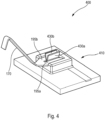
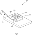
- Figures 5 and 6 illustrate another possible variant of the electrical component of Figures 1 to 3 , presenting an electrical component 500 comprising a first conductive element 510.
- the flaps 530a, 530b retain the tines 195a, 195b of the second conductive element 170 as in the preceding embodiments.
- the flaps 530a, 530b do not both extend over the entire length of the head of the first conductive element 510, as in the embodiments previously described. Rather, the flaps 530a, 530b extend over a length no more than half of that of the head of the first conductive element 510, offset from each other in the manner depicted in Figures 5 and 6 .
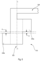
- Figure 6 illustrates in more detail the first conductive element 510 of the electrical component 500 illustrated in Figure 5 , in particular in a state prior to the execution of the fabrication steps described above in relation to Figures 1A to 1D .
- the flaps 530a, 530b of the first conductive element 510 are offset along the longitudinal axis L of the head 525. It may be advantageous to provide a slight gap G between the two flaps 530a, 530 along the direction of the longitudinal axis L, so as to facilitate the folding over of the tines of the second conductive element as depicted in Figure 5 .
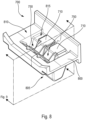
- Figures 7A to 9 there is illustrated an electrical component 700 according to a second embodiment of the invention.
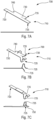
- Figures 7A, 7B, and 7C illustrate successive steps for fabricating a first conductive element 710 for an electrical component 700, and will therefore be described in turn.
- FIG. 7A, 7B, and 7C are illustrated perspective and side views of a first conductive element 710, each pair of perspective and side views illustrating the same first conductive element 710. Additionally, Figures 8 and 9 depict the first conductive element 710 as integrated into an electrical component 700.
- the electrical component 700 comprises the first conductive element 710.
- the first conductive element 710 comprises a first strip portion 720 and a second strip portion 730, which are connected by a bridge 740 to form a single, continuous piece.
- the strip portions 720 and 730 respectively comprise fingers 725, 735 which extend from the bridge 740.
- the strip portion 720 forms an extension of a leadframe element (not illustrated), which serves to connect the first conductive element to other electrical components in an electrical motor or elsewhere in the vehicle.
- the first conductive element 710 is preferably fabricated from a strip or sheet of conductive material, which is advantageous in that it allows the first conductive element 710 to be fabricated quickly by simple, inexpensive metalworking processes.
- the first conductive element 710 is preferably fabricated by a resilient, ductile, conductive metal such as copper, brass, or spring steel, though other metals or alloys may be envisaged for specific applications.
- Figure 7B illustrates a subsequent folding step.
- the fingers 725, 735 are bent into a curved configuration, for instance in the manner illustrated, by known metalworking techniques. Consequently, the curved shapes of the fingers 725, 735, and the work hardening that is incurred in the metal of the first conductive element 710 during the bending process, obtain mechanical properties in the fingers 725, 735 of the strip portions 720, 730.
- connection region 750 is formed. This connection region 750 is discussed in further detail in the following Figures.
- Figure 8 illustrates a subsequent step for fabricating the electrical component 700.
- Two first conductive elements 710 are arranged and then a plastic material 800 is overmolded about them.
- the plastic material 800 is overmolded such that a first side 805 of the first conductive elements 710 is entirely covered, and thereby rendered impervious.
- the plastic material 800 that is overmolded about the first conductive elements 710 forms a part of the housing of an electric motor, with the first side 805 constituting the exterior of said housing.
- the plastic material 800 can be considered as constituting a carrier element, similar to the carrier element 150 discussed above with respect to the preceding embodiments.
- the overmolding of the first conductive elements 710 on a second side 810 of the electrical component 700 is configured such that the first conductive elements 710 block flow of the plastic material within the mold cavity during a molding operation, and consequently remain exposed, at the very least in the proximity of the connection region 750.
- this second side 810 of the electrical component 700 is configured so as to open on or face the interior of the electrical motor.
- the plastic material 800 is overmolded so as to substantially follow the form of the first conductive elements 710, thereby forming a pocket 815.
- the pocket 815 is discussed in further detail below.
- the overmolding of the plastic material 800 may advantageously be configured so as to enclose such leadframe elements, such that the only portions thereof which are exposed are electrical connection regions such as the connection region 750 as illustrated in Figure 8 .
- two units of the first conductive element 710 are disposed in a side-by-side arrangement; however, fewer or more of the first conductive elements may be provided, and/or be disposed in other, different arrangements without departing from the scope of the invention.
- Figure 9 is a section view of the electrical component 700, at the section plane illustrated in Figure 8 .
- Figure 9 illustrates the interaction of the two fingers 725, 735, and their disposition within the pocket 815 of the electrical component 700.
- the two fingers 725, 735 of the electrical connection element 710 present contact points 900a, 900b, respectively, at which the two fingers 725, 735 are in contact with each other.
- the elasticity of the fingers 725, 735 means that another electrical component (for instance, a metal strip or tab contact element, a leadframe, finger contacts on a printed circuit board edge, or the like) may be inserted into the connection region 750; the other electrical component will push the finger 735 aside as it is inserted into the pocket 815, being retained between the fingers 725, 735 such that the contact points 900a, 900b establish electrical continuity therewith.
- electrical connections within a motor comprising an electrical component 700 can be quickly and reliably established, in a manner that offers both simplicity of fabrication and rigorous environmental protection from infiltration of water, dust, and other contaminants.
Landscapes
- Engineering & Computer Science (AREA)
- Power Engineering (AREA)
- Microelectronics & Electronic Packaging (AREA)
- Motor Or Generator Frames (AREA)
Priority Applications (2)
| Application Number | Priority Date | Filing Date | Title |
|---|---|---|---|
| EP22181701.8A EP4300788A1 (de) | 2022-06-28 | 2022-06-28 | Elektrische komponente für einen scheibenwischermotor |
| PCT/EP2023/065504 WO2024002659A1 (en) | 2022-06-28 | 2023-06-09 | Electrical component for a windscreen wiper motor |
Applications Claiming Priority (1)
| Application Number | Priority Date | Filing Date | Title |
|---|---|---|---|
| EP22181701.8A EP4300788A1 (de) | 2022-06-28 | 2022-06-28 | Elektrische komponente für einen scheibenwischermotor |
Publications (1)
| Publication Number | Publication Date |
|---|---|
| EP4300788A1 true EP4300788A1 (de) | 2024-01-03 |
Family
ID=82492337
Family Applications (1)
| Application Number | Title | Priority Date | Filing Date |
|---|---|---|---|
| EP22181701.8A Withdrawn EP4300788A1 (de) | 2022-06-28 | 2022-06-28 | Elektrische komponente für einen scheibenwischermotor |
Country Status (2)
| Country | Link |
|---|---|
| EP (1) | EP4300788A1 (de) |
| WO (1) | WO2024002659A1 (de) |
Citations (1)
| Publication number | Priority date | Publication date | Assignee | Title |
|---|---|---|---|---|
| WO2021001299A1 (en) * | 2019-07-02 | 2021-01-07 | Valeo Systèmes d'Essuyage | Wiper motor and method for the production thereof |
-
2022
- 2022-06-28 EP EP22181701.8A patent/EP4300788A1/de not_active Withdrawn
-
2023
- 2023-06-09 WO PCT/EP2023/065504 patent/WO2024002659A1/en not_active Ceased
Patent Citations (1)
| Publication number | Priority date | Publication date | Assignee | Title |
|---|---|---|---|---|
| WO2021001299A1 (en) * | 2019-07-02 | 2021-01-07 | Valeo Systèmes d'Essuyage | Wiper motor and method for the production thereof |
Also Published As
| Publication number | Publication date |
|---|---|
| WO2024002659A1 (en) | 2024-01-04 |
Similar Documents
| Publication | Publication Date | Title |
|---|---|---|
| US7554235B2 (en) | Motor cover and electric motor equipped with the same | |
| WO2000038300A1 (de) | Stellantrieb mit einem elektromotor und mit einer steuerelektronik | |
| CN105264748B (zh) | 电动助力用马达装置的供电部结构 | |
| EP1001501B1 (de) | Kohlenschleifstück | |
| KR20110025181A (ko) | 차량용 스티어링 휠 | |
| CN87105738A (zh) | 一种电动机 | |
| US9818553B2 (en) | Electric switch with rubbing contact | |
| WO2024002659A1 (en) | Electrical component for a windscreen wiper motor | |
| JP3954527B2 (ja) | ブラシホルダ装置及びモータ | |
| EP3651321B1 (de) | Verfahren zur herstellung einer motorvorrichtung | |
| US6949862B2 (en) | Brush assembly | |
| CN1034899C (zh) | 小型电动机 | |
| JP4988255B2 (ja) | ハウジング内に設けられた電子的な回路の電気的な接続のための装置および方法 | |
| US20070109748A1 (en) | Adjusting device especially for a throttle valve of an internal combustion engine | |
| CN115362604B (zh) | 引线块以及旋转连接器装置 | |
| CN114051469B (zh) | 刮水器马达及其制造方法 | |
| CN1225823C (zh) | 带电刷电动机 | |
| US6548934B1 (en) | Brush holder lead frame with integral electrical terminals | |
| EP1055277B1 (de) | Leiterbahnen mit Kommutatorbürsten für eine elektrische Antriebseinheit für Fahrzeugaggregate | |
| DE202006009247U1 (de) | Gehäuse für ein Türschloss mit Anschlussadapter | |
| CN100420126C (zh) | 接线端子组件的制造方法、接线端子组件及车辆用刮水器马达 | |
| JPH10506072A (ja) | 組み合わせ洗浄/窓ふき器コンタクトアッセンブリー | |
| JP3866548B2 (ja) | コネクタ装置及びその製造方法 | |
| CN1218337C (zh) | 微型开关及其制造方法 | |
| KR100315857B1 (ko) | 회전커넥터장치 |
Legal Events
| Date | Code | Title | Description |
|---|---|---|---|
| PUAI | Public reference made under article 153(3) epc to a published international application that has entered the european phase |
Free format text: ORIGINAL CODE: 0009012 |
|
| STAA | Information on the status of an ep patent application or granted ep patent |
Free format text: STATUS: THE APPLICATION HAS BEEN PUBLISHED |
|
| AK | Designated contracting states |
Kind code of ref document: A1 Designated state(s): AL AT BE BG CH CY CZ DE DK EE ES FI FR GB GR HR HU IE IS IT LI LT LU LV MC MK MT NL NO PL PT RO RS SE SI SK SM TR |
|
| STAA | Information on the status of an ep patent application or granted ep patent |
Free format text: STATUS: THE APPLICATION IS DEEMED TO BE WITHDRAWN |
|
| 18D | Application deemed to be withdrawn |
Effective date: 20240704 |