EP4301065A1 - Kommunikationsverfahren, -vorrichtung und -system - Google Patents
Kommunikationsverfahren, -vorrichtung und -system Download PDFInfo
- Publication number
- EP4301065A1 EP4301065A1 EP21930846.7A EP21930846A EP4301065A1 EP 4301065 A1 EP4301065 A1 EP 4301065A1 EP 21930846 A EP21930846 A EP 21930846A EP 4301065 A1 EP4301065 A1 EP 4301065A1
- Authority
- EP
- European Patent Office
- Prior art keywords
- resource
- frequency domain
- common signal
- downlink common
- monitoring location
- Prior art date
- Legal status (The legal status is an assumption and is not a legal conclusion. Google has not performed a legal analysis and makes no representation as to the accuracy of the status listed.)
- Pending
Links
- 238000000034 method Methods 0.000 title claims abstract description 131
- 238000004891 communication Methods 0.000 title claims abstract description 86
- 238000012544 monitoring process Methods 0.000 claims description 305
- 238000003860 storage Methods 0.000 claims description 20
- 238000004590 computer program Methods 0.000 claims description 12
- 230000004044 response Effects 0.000 claims description 11
- 239000000969 carrier Substances 0.000 abstract description 19
- 235000019527 sweetened beverage Nutrition 0.000 description 189
- 230000005540 biological transmission Effects 0.000 description 42
- 238000001514 detection method Methods 0.000 description 34
- 230000006870 function Effects 0.000 description 31
- 238000013461 design Methods 0.000 description 27
- 101150096310 SIB1 gene Proteins 0.000 description 22
- 238000012545 processing Methods 0.000 description 12
- 238000001228 spectrum Methods 0.000 description 12
- 238000010586 diagram Methods 0.000 description 11
- 101100533725 Mus musculus Smr3a gene Proteins 0.000 description 10
- 230000001174 ascending effect Effects 0.000 description 9
- 102100036409 Activated CDC42 kinase 1 Human genes 0.000 description 6
- 101000741965 Homo sapiens Inactive tyrosine-protein kinase PRAG1 Proteins 0.000 description 6
- 102100038659 Inactive tyrosine-protein kinase PRAG1 Human genes 0.000 description 6
- 238000010295 mobile communication Methods 0.000 description 6
- 238000001914 filtration Methods 0.000 description 5
- 238000005259 measurement Methods 0.000 description 5
- 101100274486 Mus musculus Cited2 gene Proteins 0.000 description 4
- 101150096622 Smr2 gene Proteins 0.000 description 4
- 230000009286 beneficial effect Effects 0.000 description 3
- 125000004122 cyclic group Chemical group 0.000 description 3
- 238000005516 engineering process Methods 0.000 description 3
- 238000006243 chemical reaction Methods 0.000 description 2
- 230000000295 complement effect Effects 0.000 description 2
- 230000001934 delay Effects 0.000 description 2
- 230000003190 augmentative effect Effects 0.000 description 1
- 238000013500 data storage Methods 0.000 description 1
- 238000009776 industrial production Methods 0.000 description 1
- 230000000977 initiatory effect Effects 0.000 description 1
- 230000003993 interaction Effects 0.000 description 1
- 230000003287 optical effect Effects 0.000 description 1
- 239000004065 semiconductor Substances 0.000 description 1
- 230000008054 signal transmission Effects 0.000 description 1
- 230000011664 signaling Effects 0.000 description 1
- 239000007787 solid Substances 0.000 description 1
- 230000001360 synchronised effect Effects 0.000 description 1
- XLYOFNOQVPJJNP-UHFFFAOYSA-N water Substances O XLYOFNOQVPJJNP-UHFFFAOYSA-N 0.000 description 1
Images



Classifications
-
- H—ELECTRICITY
- H04—ELECTRIC COMMUNICATION TECHNIQUE
- H04W—WIRELESS COMMUNICATION NETWORKS
- H04W74/00—Wireless channel access
- H04W74/08—Non-scheduled access, e.g. ALOHA
- H04W74/0833—Random access procedures, e.g. with 4-step access
-
- H—ELECTRICITY
- H04—ELECTRIC COMMUNICATION TECHNIQUE
- H04W—WIRELESS COMMUNICATION NETWORKS
- H04W74/00—Wireless channel access
- H04W74/002—Transmission of channel access control information
- H04W74/006—Transmission of channel access control information in the downlink, i.e. towards the terminal
-
- H—ELECTRICITY
- H04—ELECTRIC COMMUNICATION TECHNIQUE
- H04L—TRANSMISSION OF DIGITAL INFORMATION, e.g. TELEGRAPHIC COMMUNICATION
- H04L5/00—Arrangements affording multiple use of the transmission path
- H04L5/003—Arrangements for allocating sub-channels of the transmission path
- H04L5/0048—Allocation of pilot signals, i.e. of signals known to the receiver
-
- H—ELECTRICITY
- H04—ELECTRIC COMMUNICATION TECHNIQUE
- H04L—TRANSMISSION OF DIGITAL INFORMATION, e.g. TELEGRAPHIC COMMUNICATION
- H04L5/00—Arrangements affording multiple use of the transmission path
- H04L5/0091—Signalling for the administration of the divided path, e.g. signalling of configuration information
- H04L5/0096—Indication of changes in allocation
-
- H—ELECTRICITY
- H04—ELECTRIC COMMUNICATION TECHNIQUE
- H04W—WIRELESS COMMUNICATION NETWORKS
- H04W74/00—Wireless channel access
- H04W74/08—Non-scheduled access, e.g. ALOHA
- H04W74/0866—Non-scheduled access, e.g. ALOHA using a dedicated channel for access
Definitions
- Embodiments of this application relate to the field of wireless communication technologies, and specifically, to a communication method, apparatus, and system.
- a 5G communication system is committed to supporting higher system performance, and supports a plurality of service types, different deployment scenarios, and a wider spectrum range.
- the plurality of service types supported by the 5G communication system include enhanced mobile broadband (enhanced mobile broadband, eMBB), massive machine type communication (massive machine type communication, mMTC), ultra-reliable and low-latency communications (ultra-reliable and low latency communications, URLLC), a multimedia broadcast multicast service (multimedia broadcast multicast service, MBMS), a positioning service, and the like.
- the 5G communication system supports ultra-reliable and low latency services.
- URLLC services There are many types of URLLC services. Typical examples include industrial control, industrial production procedure automation, human-computer interaction, telemedicine, and the like.
- a bottleneck of a data transmission delay in 5G new radio lies in uplink and downlink waiting delays.
- existing time division duplex (time division duplex, TDD) frame structures configured in macro cells are usually downlink transmission-dominant structures (referred to as DL-dominant frame structures), resulting in a relatively large waiting delay in uplink transmission (including uplink data transmission and downlink transmission feedback).
- a method for reducing this waiting delay is to configure a shorter uplink-downlink switching period, for example, a self-contained (Self-contain) frame structure, to increase a proportion of uplink transmission symbols and reduce the uplink waiting delay.
- This method is not friendly to coexistence of hybrid services in aspects of causing larger switching overheads and pilot/control overheads, difficult product implementation, and heterogeneous interference with the mainstream DL-dominant frame structures of macro cells.
- Another method for reducing this waiting delay is to configure supplementary uplink (supplementary uplink, SUL) carriers.
- SUL supplementary uplink
- one downlink TDD carrier is further associated with a carrier resource of another frequency division duplex (frequency division duplex, FDD) band, and the FDD carrier resource is of an uplink-only frame structure.
- FDD frequency division duplex
- This method has the following problems: Not all bands have configurable SUL resources.
- the SUL is of an uplink-only frame structure, only the uplink waiting delay can be reduced, and for some scenarios in which uplink part-dominant (referred to as UL-dominant) TDD frame structures need to be deployed, a downlink waiting delay cannot be reduced by configuring the SUL.
- Embodiments of this application provide a communication method and apparatus, to reduce a waiting delay in an initial access process.
- a communication method is provided.
- the method may be performed by a terminal device or a chip system in the terminal device, and the method includes:
- the random access resource set of the terminal device includes random access sets separately located on at least two frequency domain resources. Because the at least two frequency domain resources correspond to different uplink-downlink configurations, the terminal device may flexibly select, based on the uplink-downlink configurations, a suitable random access resource from the random access resources corresponding to the at least two frequency domain resources to perform random access, so that a waiting delay in sending the random access preamble can be reduced, thereby reducing an access delay and improving system flexibility.
- the method further includes:
- the determining a downlink common signal resource subset includes: receiving first indication information and second indication information, determining a first downlink common signal resource subset based on the first indication information, where a downlink common signal in the first downlink common signal resource subset belongs to the first frequency domain resource, and determining a second downlink common signal resource subset based on the second indication information, where a downlink common signal in the second downlink common signal resource subset belongs to the second frequency domain resource, and the downlink common signal resource subset is a union set of the first downlink common signal resource subset and the second downlink common signal resource subset.
- the association relationship includes at least one of a first association relationship, a second association relationship, a third association relationship, or a fourth association relationship
- the first association relationship is an association relationship between a first random access resource set on the first frequency domain resource and the first downlink common signal resource subset
- the second association relationship is an association relationship between a second random access resource set on the second frequency domain resource and the first downlink common signal resource subset
- the third association relationship is an association relationship between the first random access resource set on the first frequency domain resource and the second downlink common signal resource subset
- the fourth association relationship is an association relationship between the second random access resource set on the second frequency domain resource and the second downlink common signal resource subset.
- two pieces of indication information are used to separately indicate downlink common signal resources on the first frequency domain resource and the second frequency domain resource, to match parameters such as frame structures and subcarrier spacings of the two frequency domain resources, thereby improving indication efficiency.
- the determining a downlink common signal resource subset includes: receiving third indication information, and determining a third downlink common signal resource subset based on the third indication information, where the downlink common signal resource subset is equal to the third downlink common signal resource subset, the third downlink common signal resource subset is a subset of a third downlink common signal resource set, the third downlink common signal resource set corresponds to a third downlink common signal pattern, and the third downlink common signal resource set includes a downlink common signal resource on the first frequency domain resource and a downlink common signal resource on the second frequency domain resource.
- the method further includes: receiving downlink common signal pattern indication information, where the downlink common signal pattern indication information indicates an index of the third downlink common signal pattern, and the third downlink common signal pattern is used to define a time domain location of each common signal in the third downlink common signal set on the first frequency domain resource or the second frequency domain resource.
- one pattern is used to jointly indicate a set of downlink common signal resources on the first frequency domain resource and the second frequency domain resource, and then one piece of indication information indicates an index that is in the set and that corresponds to a common signal belonging to the downlink common signal resource subset, so that configuration flexibility can be improved.
- the method further includes:
- the second DCI is detected at one or more PDCCH detection locations of the first frequency domain resource or the second frequency domain resource, and therefore a suitable resource may be flexibly selected from at least two frequency domain resources based on uplink-downlink configurations to send the second DCI for scheduling a random access response, so that a delay in sending the second DCI can be reduced, and system flexibility can be improved.
- a symbol on which the second monitoring location is located is a downlink symbol or a flexible symbol
- a symbol on which the third monitoring location is located includes an uplink symbol
- the second DCI is detected at the second monitoring location; or when a second monitoring location in the second PDCCH monitoring location set and a third monitoring location in the third PDCCH monitoring location set overlap in time domain, a symbol on which the second monitoring location is located is a downlink symbol or a flexible symbol, and a symbol on which the third monitoring location is located is also a downlink symbol or a flexible symbol
- the second DCI is monitored at a fourth monitoring location, where the fourth monitoring location is one of the second monitoring location and the third monitoring location.
- the second DCI is scrambled by using a random access radio network temporary identifier RA-RNTI, and a value of the RA-RNTI is determined based on a frequency domain resource on which the first random access resource is located and a time-frequency location of the first random access resource in the frequency domain resource on which the first random access resource is located.
- RA-RNTI random access radio network temporary identifier
- the method further includes:
- the RAR carries indication information sent by the RAR on the first frequency domain resource or the second frequency domain resource, and therefore a frequency domain resource that has a closest uplink part may be selected based on frame structures of the two frequency domain resources to send the first PUSCH, so that a delay in sending the first PUSCH is reduced.
- the method further includes:
- the third DCI is detected at one or more PDCCH detection locations of the first frequency domain resource or the second frequency domain resource, and therefore a suitable resource may be flexibly selected from at least two frequency domain resources based on uplink-downlink configurations to send the third DCI for scheduling the third PDSCH, so that a delay in sending the third DCI can be reduced, and system flexibility can be improved.
- the third DCI is detected at the fifth monitoring location; or when a fifth monitoring location in the fourth PDCCH monitoring set and a sixth monitoring location in the fifth PDCCH monitoring set overlap in time domain, a symbol on which the fifth monitoring location is located is a downlink symbol or a flexible symbol, and a symbol on which the sixth monitoring location is located is a downlink symbol or a flexible symbol, the third DCI is detected at a seventh monitoring location, where the seventh monitoring location is a preset monitoring location in the fifth monitoring location and the sixth monitoring location.
- the third DCI carries information indicating a sixth frequency domain resource
- the sixth frequency domain resource belongs to the first frequency domain resource or the second frequency domain resource
- the method further includes: sending feedback information of the third PDSCH on the sixth frequency domain resource.
- the feedback information of the third PDSCH is carried by using a second PUCCH.
- the third DCI indicates that the second PUCCH is sent on the first frequency domain resource or the second frequency domain resource, and therefore a frequency domain resource that has a closest uplink part may be selected based on frame structures of the two frequency domain resources to send the second PUCCH, so that a delay in sending the second PUCCH is reduced.
- a communication method is provided.
- the method may be performed by a network device or a chip system in the network device, and the method includes:
- the sending a first downlink common signal to a terminal device includes: sending a downlink common signal on a downlink common signal resource in a downlink common signal resource subset, where the downlink common signal resource subset includes the first downlink common signal.
- the method further includes: determining, based on an association relationship between the random access resource set and the downlink common signal resource subset, a random access resource subset corresponding to a resource of the first downlink common signal, where the association relationship includes a correspondence between a downlink common signal resource in the downlink common signal resource subset and a random access resource subset in the random access resource set; and the resource of the first downlink common signal is a resource corresponding to the first downlink common signal, and is a resource in the downlink common signal resource subset.
- the system information further carries first indication information and second indication information, the first indication information indicates location information of a first downlink common signal resource subset, the second indication information indicates location information of a second downlink common signal resource subset, a downlink common signal in the first downlink common signal resource subset belongs to the first frequency domain resource, a downlink common signal in the second downlink common signal resource subset belongs to the second frequency domain resource, and the downlink common signal resource subset is a union set of the first downlink common signal resource subset and the second downlink common signal resource subset.
- the association relationship includes at least one of a first association relationship, a second association relationship, a third association relationship, or a fourth association relationship
- the first association relationship is an association relationship between a first random access resource set on the first frequency domain resource and the first downlink common signal resource subset
- the second association relationship is an association relationship between a second random access resource set on the second frequency domain resource and the first downlink common signal resource subset
- the third association relationship is an association relationship between the first random access resource set on the first frequency domain resource and the second downlink common signal resource subset
- the fourth association relationship is an association relationship between the second random access resource set on the second frequency domain resource and the second downlink common signal resource subset.
- the system information further carries third indication information, the third indication information indicates location information of a third downlink common signal resource subset, the downlink common signal resource subset is equal to the third downlink common signal resource subset, the third downlink common signal resource subset is a subset of a third downlink common signal resource set, the third downlink common signal resource set corresponds to a third downlink common signal pattern, and common signal resources included in the third downlink common signal resource set are located on the first frequency domain resource and the second frequency domain resource.
- the third indication information indicates location information of a third downlink common signal resource subset
- the downlink common signal resource subset is equal to the third downlink common signal resource subset
- the third downlink common signal resource subset is a subset of a third downlink common signal resource set
- the third downlink common signal resource set corresponds to a third downlink common signal pattern
- common signal resources included in the third downlink common signal resource set are located on the first frequency domain resource and the second frequency domain resource.
- the method further includes: sending common signal pattern indication information, where the downlink common signal pattern indication information indicates an index of the third downlink common signal pattern, and the third downlink common signal pattern is used to define a time domain location of each common signal in the third downlink common signal set on the first frequency domain resource or the second frequency domain resource.
- the method further includes:
- the method further includes:
- the second DCI is scrambled by using a random access radio network temporary identifier RA-RNTI, and a value of the RA-RNTI is determined based on a frequency domain resource on which the first random access resource is located and a time-frequency location of the first random access resource in the frequency domain resource on which the first random access resource is located.
- RA-RNTI random access radio network temporary identifier
- the method further includes:
- the method further includes:
- the third DCI is detected at the fifth monitoring location; or when a fifth monitoring location in the fourth PDCCH monitoring set and a sixth monitoring location in the fifth PDCCH monitoring set overlap in time domain, a symbol on which the fifth monitoring location is located is a downlink symbol or a flexible symbol, and a symbol on which the sixth monitoring location is located is a downlink symbol or a flexible symbol, the third DCI is sent at a seventh monitoring location, where the seventh monitoring location is a preset monitoring location in the fifth monitoring location and the sixth monitoring location.
- the third DCI carries information indicating a sixth frequency domain resource
- the sixth frequency domain resource belongs to the first frequency domain resource or the second frequency domain resource
- the method further includes: receiving feedback information HARQ-ACK of the third PDSCH on the sixth frequency domain resource, where the sixth frequency domain resource belongs to the first frequency domain resource or the second frequency domain resource.
- a communication method is provided.
- the method may be performed by a terminal device or a chip system in the terminal device, and the method includes:
- a communication method is provided.
- the method may be performed by a network device or a chip system in the network device, and the method includes:
- this application further provides a communication apparatus.
- the apparatus may implement the communication method according to the first aspect, the second aspect, the third aspect, or the fourth aspect.
- the apparatus may be a terminal device or a network device, or may be another apparatus that can implement the foregoing communication method.
- the apparatus may implement the foregoing method by software, hardware, or hardware executing corresponding software.
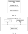
- the apparatus may include a processor and a memory.
- the processor is configured to support the apparatus in performing a corresponding function in the method according to any one of the foregoing aspects.
- the memory is configured to be coupled to the processor, and stores program instructions and data that are necessary for the apparatus.
- the apparatus may further include a communication interface, configured to support communication between the apparatus and another apparatus.
- the communication interface may be a transceiver or a transceiver circuit.
- an embodiment of this application provides a communication system.
- the system includes the communication apparatus according to the foregoing aspect.
- Still another aspect of this application provides a computer-readable storage medium.
- the computer-readable storage medium stores instructions.
- the instructions run on a computer, the computer is enabled to perform the methods according to the foregoing aspects.
- Still another aspect of this application provides a computer program product including instructions.
- the computer program product runs on a computer, the computer is enabled to perform the methods according to the foregoing aspects.
- the chip system includes a processor, and may further include a memory.
- the chip system is configured to implement the method in any one of the foregoing aspects.
- any apparatus, computer storage medium, computer program product, chip system, or communication system provided above is configured to perform a corresponding method provided above. Therefore, for beneficial effects that can be achieved by the apparatus, the computer storage medium, the computer program product, the chip system, or the communication system, refer to beneficial effects of corresponding solutions in the corresponding method provided above. Details are not described herein again.
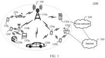
- FIG. 1 is a schematic diagram of an architecture of a communication system 1100 to which embodiments of this application are applied.
- the communication system includes a radio access network 100 and a core network 200.
- the communication system 1100 may further include an internet 300.
- the radio access network 100 may include at least one radio access network device (for example, 110a and 110b in FIG. 1 ), and may further include at least one terminal (for example, 120a to 120j in FIG. 1 ).
- the terminal is wirelessly connected to the radio access network device, and the radio access network device is wirelessly or wiredly connected to the core network.
- a core network device and the radio access network device may be independent and different physical devices, or functions of the core network device and logical functions of the radio access network device are integrated into a same physical device, or some of functions of the core network device and some of functions of the radio access network device are integrated into one physical device.
- a wired or wireless manner may be used for connection between terminals and between radio access network devices.
- FIG. 1 is only a schematic diagram.
- the communication system may further include another network device, for example, may further include a wireless relay device and a wireless backhaul device, which are not shown in FIG. 1 .
- the radio access network device may be a base station (base station), an evolved NodeB (evolved NodeB, eNodeB), a transmission reception point (transmission reception point, TRP), or a next generation NodeB (next generation NodeB, gNB) in a 5th generation (5th generation, 5G) mobile communication system, a next generation NodeB in a 6th generation (6th generation, 6G) mobile communication system, a base station in a future mobile communication system, an access node in a Wi-Fi system, or the like.
- base station base station
- evolved NodeB evolved NodeB
- eNodeB evolved NodeB
- TRP transmission reception point
- next generation NodeB next generation NodeB (next generation NodeB, gNB) in a 5th generation (5th generation, 5G) mobile communication system
- a next generation NodeB in a 6th generation (6th generation, 6G) mobile communication system a base station in a future mobile communication system
- the radio access network device may be a module or a unit that implements some functions of the base station, for example, may be a central unit (central unit, CU), or may be a distributed unit (distributed unit, DU).
- the radio access network device may be a macro base station (for example, 110a in FIG. 1 ), or may be a micro base station or an indoor station (for example, 110b in FIG. 1 ), or may be a relay node, a donor node, or the like.
- a specific technology and a specific device form that are used by the radio access network device are not limited in embodiments of this application. For ease of description, the following describes an example in which a base station is used as a radio access network device.
- the terminal may be a mobile phone, a tablet computer, a computer with a wireless sending/receiving function, a wearable device, a vehicle, an uncrewed aerial vehicle, a helicopter, an airplane, a ship, a robot, a robotic arm, a smart household device, or the like.
- a specific technology and a specific device form that are used by the terminal are not limited in embodiments of this application.
- the base station and the terminal may be fixed or movable.
- the base station and the terminal may be deployed on land, including an indoor, an outdoor, a handheld, or a vehicle-mounted base station and an indoor, an outdoor, a handheld, or a vehicle-mounted terminal device; or may be deployed on a water surface; or may be deployed on an airplane, a balloon, or a satellite in the air.
- Application scenarios of the base station and the terminal are not limited in embodiments of this application.
- Roles of the base station and the terminal may be opposite.
- a helicopter or an uncrewed aerial vehicle 120i in FIG. 1 may be configured as a mobile base station.
- the terminal 120i is a base station.
- 120i is a terminal, in other words, communication between 110a and 120i is performed by using a wireless air interface protocol.
- communication may alternatively be performed between 110a and 120i by using an interface protocol between base stations.
- 120i is also a base station relative to 110a. Therefore, the base station and the terminal may be collectively referred to as a communication apparatus, 110a and 110b in FIG. 1 may be referred to as communication apparatuses having a base station function, and 120a to 120j in FIG. 1 may be referred to as communication apparatuses having a terminal function.
- a function of the base station may be performed by a module (for example, a chip) in the base station, or may be performed by a control subsystem including a base station function.
- the control subsystem including a base station function herein may be a control center in the foregoing application scenarios such as a smart grid, industrial control, intelligent transportation, and a smart city.
- a function of the terminal may be performed by a module (for example, a chip or a modem) in the terminal, or may be performed by an apparatus including a terminal function.
- the base station sends a downlink signal or downlink information to the terminal, where the downlink information is carried on a downlink channel.
- the terminal sends an uplink signal or uplink information to the base station, where the uplink information is carried on an uplink channel.
- the terminal needs to establish a wireless connection to a cell controlled by the base station.
- a cell that establishes a wireless connection to the terminal is referred to as a serving cell of the terminal.
- the terminal is further exposed to interference from a signal of an adjacent cell.
- a process in which the terminal device switches from an idle (idle) mode to a connected (connected) mode when accessing a cell in an NR system mainly includes three steps: synchronization signal and PBCH (synchronization signal and PBCH block, SSB) detection, system information block 1 (system information block 1, SIB1) reception, and a random access process.
- PBCH synchronization signal and PBCH block, SSB
- SIB1 system information block 1, SIB1
- An SSB includes a synchronization signal (synchronization signal, SS) and a physical broadcast channel (physical broadcast channel, PBCH).
- the synchronization signal includes a primary synchronization signal (Primary SS, PSS) and a secondary synchronization signal (secondary SS, SSS).
- the physical broadcast channel carries a master information block (master information block, MIB) of an accessed cell.
- the synchronization signal and the physical broadcast channel are used to obtain a physical cell ID, perform downlink timing, and obtain the most important system information MIB.
- the physical cell ID is jointly carried by the PSS and the SSS.
- the SSB occupies four consecutive symbols in time domain, and occupies 20 resource blocks (resource block, RB) in frequency domain.
- a time domain location of the SSB is defined by an SSB pattern (pattern).
- One SSB pattern specifies a time domain location of one group of consecutive SSBs in a half-frame (Half-Frame).
- Half-Frame a time domain location of one group of consecutive SSBs in a half-frame
- 3GPP defines five SSB patterns for the licensed spectrum (unshared spectrum), and each SSB pattern has an applicable subcarrier spacing (subcarrier spacing, SCS).
- SCS subcarrier spacing
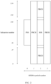
- a current mainstream NR band n78 (3.3 GHz to 3.8 GHz) is used as an example. The band supports only one SSB pattern. As shown in FIG. 3 , for example, a subcarrier spacing applicable to the SSB pattern is 30 kHz.
- One SSB pattern includes eight SSBs, SSB indexes (index) are 0 to 7, and the SSB pattern is located in the first four slots (slot) in a half-frame. Each slot includes two SSBs whose start symbols are #2 and #8.
- the terminal device After determining the time-frequency location of the DCI for scheduling the SIB1, the terminal device blindly detects the DCI at the time-frequency location of the DCI. If the DCI is detected, the terminal device may receive the PDSCH on a specified time-frequency resource based on an indication of the DCI and a specified parameter, to obtain the SIB 1.
- a main function of the SIB1 is to complete configuration of a primary cell (Primary Cell, PCell), so that a terminal device in the idle mode listens to a paging message, or completes uplink timing synchronization through random access to switch to the connected mode.
- a frequency domain offset (offset) is first configured for the SIB 1 in NR to determine a frequency domain anchor.
- One serving cell (denoted as a PCell) is configured based on the anchor.
- a TDD frame structure, a downlink (downlink, DL) configuration, and an uplink (uplink, UL) configuration of the PCell are mainly included.
- the UL configuration further includes NUL and SUL.
- Downlink common parameters of the PCell are mainly configured.
- a plurality of resource grids are first configured based on a subcarrier spacing SCS.
- Each resource grid is a resource division of the PCell in a case of the SCS.
- An initial downlink bandwidth part is further configured by using an information element InitialDLBWP, to indicate a bandwidth part (bandwidth part, BWP) used for downlink transmission before initial access.
- InitialDLBWP mainly includes a physical downlink control channel (physical downlink control channel, PDCCH) configuration and a PDSCH configuration.
- NUL configuration Normal uplink common parameters of the PCell are mainly configured.
- a plurality of resource grids are first configured based on a subcarrier spacing SCS.
- Each resource grid is a resource division of the PCell in a case of the SCS.
- a BWP used for uplink transmission before initial access is further indicated by using an information element InitialULBWP.
- InitialULBWP mainly includes a physical uplink shared channel (physical uplink shared channel, PUSCH) configuration, a physical uplink control channel (physical uplink control channel, PUCCH) configuration, and a random access channel (random access channel, RACH) configuration.
- SUL configuration Auxiliary uplink common parameters of the PCell are mainly configured. For some bands, 3GPP allows an SUL to be configured. In other words, one cell includes one SUL carrier in addition to one normal downlink carrier (carrier) and one normal uplink carrier. Currently, all SUL carriers are of an uplink-only frame structure.
- the SUL configuration also includes the information element initialULBWP, and initialULBWP also includes the RACH configuration.
- the terminal device obtains the most basic information of the PCell by receiving the SIB1, and therefore, may receive more system information based on a configuration parameter, and may choose to remain in the idle mode, and periodically listen to downlink paging.
- the terminal device initiates random access by using a configured RACH, obtains uplink timing synchronization, and obtains a cell-radio network temporary identifier (Cell-Radio Network Temporary Identifier, C-RNTI), to receive a specific parameter configuration of the terminal device and perform uplink and downlink transmission.
- C-RNTI Cell-Radio Network Temporary Identifier
- Random access random access, RA
- a 4-step RA procedure is as follows:
- the Msg1 is a physical random access channel (physical random access channel, PRACH).
- PRACH physical random access channel
- the terminal device may send a random access preamble preamble to the network device on an indicated RACH time-frequency resource.
- a RACH time domain location is indicated by an information element RACHConfig in the SIB 1.
- RACHConfig in the SIB 1.
- a slot is used as a period for repetition. Each slot may have one or more RACH occasions (occasion), and both a start symbol and a length of the RACH occasion are configured by a higher layer.
- a maximum of eight RACH frequency domain locations are available, and an RB occupied by each location is configured by using higher layer signaling.
- Random access resources include a RACH occasion and a RACH preamble (preamble).
- the RACH occasion may also be referred to as a RACH time-frequency resource. All of a RACH occasion selected by the terminal device, a preamble to be sent by the terminal device, and a spatial filtering setting (for example, a transmit beam) to be used by the terminal device need to be determined based on an associated SSB index.
- An association relationship between an SSB and a RACH resource (SSB-RACH Association) defines a correspondence between an SSB and a RACH resource. SSBs are in a one-to-one correspondence with SSB indexes.
- the terminal device determines active (active) SSB indexes, namely, actively sent SSB indexes, based on an information element ssb-PositioninBurst in the SIB1. Then the active SSB indexes are sorted in ascending order, RACH occasions are sorted in a frequency-first-time-second order, and the active SSB indexes and the RACH occasions are associated one by one. There are two cases for the SSB-RACH association. As shown in Table 1, one SSB index is associated with at least one RACH occasion. Alternatively, as shown in Table 2, a plurality of SSB indexes are associated with one RACH occasion, but are associated with different preamble index sets corresponding to the RACH occasion.
- Table 1 SSB index RACH occasion index 0 ⁇ #0, #1, ..., #(N-1) ⁇ Inactive (Inactive) NULL 2 ⁇ #N, #(N+1), ..., #(2N-1) ⁇ ... ... Table 2 SSB index RACH occasion index Preamble index 0 #0 #0, #1, ..., #31 Inactive NULL NULL 2 #0 #32, #33, ..., #63 3 #1 #0, #1, ..., #31 4 #1 #32, #33, ..., #63 ... ... ...
- the terminal device measures an SSB, and chooses, based on reference signal received power (Reference Signal Received Power, RSRP) of the SSB, whether to initiate random access on an NUL or an SUL.
- RSRP Reference Signal Received Power
- an uplink carrier for initiating random access is determined, ACKs/NACKs of the Msg1, the Msg3, and the Msg4 are all sent on the same uplink carrier.
- an SSB index of an SSB whose RSRP is greater than a specified threshold (configured by a higher layer) is selected, and a RACH occasion and a preamble index set that can be selected are determined based on the SSB-RACH association.
- the terminal device selects a RACH occasion and a preamble from the plurality of RACH occasions and preamble index sets according to the selection criterion. For example, the terminal device may select the preamble based on a size of the Msg3.
- the terminal device randomly selects a RACH occasion and a preamble from the plurality of RACH occasions and preamble index sets.
- the Msg1 is sent based on a spatial filtering setting used when a corresponding SSB is received. It should be noted that the Msg1 can be sent only on an uplink symbol, and time domain locations at which uplink symbols are located are determined based on a TDD frame structure in a PCell configuration.
- the Msg2 is a random access response (Random Access Response, RAR).
- RAR Random Access Response
- the terminal device monitors, in a specified time domain window and a type 1 (Type 1) common search space (Common SS, CSS), DCI that is sent by the network device and that is scrambled by using a random access radio network temporary identifier (Random Access RNTI, RA-RNTI).
- Type 1 Common Search space
- RA-RNTI random access radio network temporary identifier
- a time domain location and a frequency domain location of the type 1 CSS are configured in the foregoing information element InitialDLBWP.
- the terminal device receives a PDSCH scheduled by using the DCI.
- a medium access control (medium access control, MAC) protocol data unit (Protocol Data Unit, PDU) carried on the PDSCH carries a plurality of sub-protocol data units subPDUs.
- Each subPDU includes one MAC header (header) to indicate one preamble index, and includes one MAC RAR.
- the RAR includes uplink scheduling information for a terminal device that sends the preamble.
- the RAR has three main functions: sending an initial uplink transmission timing advance (Timing Advance, TA) to help the terminal device complete uplink timing synchronization; sending a temporary cell-radio network temporary identifier (Temporary C-RNTI, TC-RNTI) to replace the C-RNTI for use by the terminal device before initial access is completed; and sending an uplink grant (UL grant) to schedule a PUSCH to carry the subsequent Msg3 for sending.
- Timing Advance TA
- Temporal C-RNTI Temporal C-RNTI
- TC-RNTI temporary cell-radio network temporary identifier
- UL grant uplink grant
- the terminal device sends the Msg3 to the network device on a scheduled PUSCH based on a TA indicated by the RAR.
- Data on the PUSCH is scrambled by using a TC-RNTI, and data content on the PUSCH includes an identifier (identifier, ID) of the terminal device.
- the terminal device After sending the Msg3, the terminal device detects, in a corresponding time window, DCI that is sent by the network device and that is scrambled by using a TC-RNTI (Temporary C-RNTI, temporary cell-radio network temporary identifier). If the DCI is detected, the terminal device further receives a corresponding PDSCH.
- the PDSCH includes a contention resolution identifier (contention resolution identifier). If the contention resolution identifier is equal to the ID of the terminal device, it indicates that conflict resolution succeeds, and the terminal device converts the TC-RNTI into a C-RNTI.
- a 2-step RACH procedure is as follows:
- the MsgA is a RACH.
- the terminal device sends the RACH to the network device, and then sends a PUSCH on a PUSCH sending occasion.
- the RACH and the PUSCH correspond to the Msg1 and the Msg3 in the 4-step RACH.
- a candidate PUSCH sending occasion is configured by a higher layer.
- a PUSCH sending occasion selected by the terminal device is associated with RACH resource selection, and a parameter for sending a PUSCH on the sending occasion by the terminal device is also configured by a higher layer.
- the network device If the network device successfully receives the RACH and the PUSCH that are sent by the terminal device, the network device sends a Msg4 to the terminal device.
- the Msg4 carries a contention resolution identifier. In this case, the random access procedure ends. Otherwise, if the network device successfully receives the RACH but fails to receive the PUSCH, the network device sends a fallback indication (fallback indication) to the terminal device.
- the fallback indication herein is equivalent to the Msg2 in the 4-step RACH. Then the terminal device falls back to the 4-step RACH to send a Msg3 and receive a Msg4.
- an SSB and an SIB1 are sent on downlink symbols
- ACKs/NACKs of a Msg1, a Msg3, and a Msg4 are sent on uplink symbols
- a Msg2 and the Msg4 are sent on downlink symbols.
- each time of uplink-downlink conversion introduces a relatively large waiting delay.
- the terminal device after receiving an SIB 1, the terminal device needs to wait for more than 1 slot to send a Msg1, and after receiving an RAR, the terminal device further needs to wait for more than 2 slots to receive a Msg3.
- Existing NR further supports SUL-based random access. If the terminal device selects an SUL to perform random access, a waiting delay of uplink transmission can be reduced to some extent, but the following problems exist: Not all bands have associated SUL carriers. Therefore, SUL-based random access is not a universal solution.
- the SUL carrier is of an uplink-only frame structure. Therefore, the SUL carrier cannot complement a normal TDD frame structure. Consequently, the DL waiting delay cannot be reduced. For a DL-dominant frame structure, a DL waiting delay is approximately 1 ms to 1.5 ms, but for another frame structure, a DL waiting delay is relatively large.
- the network device can send sufficient SSBs to complete downlink beam scanning, to be specific, the SSBs are sequentially sent at different time domain locations by using different transmit beams, to ensure that UE in different directions can obtain relatively large received signal power.
- the network device does not have sufficient DL symbols in one uplink-downlink switching period to complete SSB beam scanning. Consequently, some terminals may fail to obtain SSBs through detection. If SSB scanning is extended to a next uplink-downlink switching period or a period after the next uplink-downlink switching period, an SSB detection delay is relatively large.
- this application provides an initial access method based on two frequency domain resources. Further, the random access method supports dynamic frequency domain resource selection and switching. Two frequency domain resources with different uplink-downlink configurations or even complementary uplink-downlink configurations are configured, and a network device and a terminal device are allowed to flexibly select a frequency domain resource to perform uplink and downlink transmission, so that a waiting delay in each information transmission phase in the initial access process is reduced.
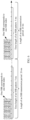
- the network device sends an SSB to the terminal device.
- the terminal device performs downlink synchronization by detecting the SSB.
- the terminal device receives an SIB1 based on an indication of the SSB, to obtain basic information of a cell, for example, two frequency domain resources that have different uplink-downlink configurations and that are included in the cell, and an active SSB resource set and a RACH resource set of the two frequency domain resources.
- the terminal device obtains an association relationship between an SSB and a RACH resource, selects a first SSB resource from the active SSB resource set based on measured SSB received signal power strength, to determine a first RACH resource subset corresponding to the first SSB resource, and selects a RACH resource from the first RACH resource subset to initiate random access.
- RACH resources associated with the first SSB resource may include RACH resources on a first frequency domain resource and a second frequency domain resource. Therefore, the terminal device may select a closest uplink symbol from the two frequency domain resources to initiate random access, so that a random access waiting delay is reduced.
- the first frequency domain resource and the second frequency domain resource may be two carriers or two BWPs.
- the network device sends the second DCI to the terminal device to schedule a random access response RAR.
- the second DCI may be sent on a downlink symbol of the first frequency domain resource, the second frequency domain resource, or the first frequency domain resource and the second frequency domain resource. Therefore, a sending waiting delay is reduced.
- the RAR indicates, to the terminal device, a frequency domain resource on which a Msg3 is to be sent, and the network device may select a closest frequency domain resource that has an uplink symbol to carry the Msg3, so that a waiting delay of the terminal device is reduced. Then the network device sends third DCI to the terminal device to schedule a Msg4.
- the third DCI may also be sent on a downlink symbol of the first frequency domain resource, the second frequency domain resource, or the first frequency domain resource and the second frequency domain resource. Therefore, a sending waiting delay is reduced.
- the third DCI further indicates a frequency domain resource on which feedback information carrying the Msg4 is to be sent, and the network device may select a closest uplink symbol in time to carry the feedback information, so that a waiting delay of the terminal device is reduced.
- downlink common signal transmission in an initial access phase has two phases.
- the first phase corresponds to first-type downlink common signals
- the second phase corresponds to second-type downlink common signals.
- the first-type downlink common signals include one or more downlink common signals, and any one of the downlink common signals includes a synchronization signal (synchronization signal, SS) and a first broadcast channel
- the second-type downlink common signals include one or more downlink common signals, and any one of the downlink common signals includes a second broadcast channel.
- the first-type downlink common signal is an SSB
- the first broadcast channel carries an MIB
- the second broadcast channel carries an SIB 1.
- the first-type downlink common signals include one or more downlink common signals, and any one of the downlink common signals includes an SS; and the second-type downlink common signals include one or more downlink common signals, and any one of the downlink common signals includes a third broadcast channel.
- the third broadcast channel carries an MIB and an SIB 1. Specific forms and content of the first-type downlink common signal and the second-type downlink common signal are not limited in this application.
- the first-type downlink common signals are periodically transmitted.
- One period includes one pattern, one pattern includes one or more time-frequency locations used to transmit the first-type downlink common signal, first-type downlink common signals at different time-frequency locations form a common signal set, and one pattern specifies an index and a time-frequency resource location of each common signal in the set, in other words, common signals are in a one-to-one correspondence with indexes and time-frequency locations.
- the first-type downlink common signal is an SSB, and the SSB is periodically transmitted.
- a period is 20 ms
- one period includes one SSB pattern
- one pattern includes eight or more time-frequency locations for transmitting SSBs
- each time-frequency location corresponds to one SSB index.
- An SSB time-frequency resource included in one SSB pattern may correspond to one time unit, and a length of the time unit may be less than the SSB transmission period.
- an SSB transmission period in NR is 20 ms, but a length of a time unit corresponding to an SSB pattern is 5 ms, and corresponding time-frequency locations for transmitting SSBs all fall within 5 ms.
- transmission parameters of first-type downlink common signals at different time-frequency locations in one pattern may be different. For example, sending filtering parameters or transmit beams used are different.
- the first-type downlink common signal is an SSB
- the second-type downlink common signal is an SIB1.
- One SSB pattern includes a plurality of SSB indexes, and each SSB index corresponds to one time-frequency location, and is used to transmit DCI for scheduling the SIB1.
- An embodiment of a communication method provided in this application is applied to a process in which a terminal device accesses a network device.
- the method includes the following steps.
- each of the first-type downlink common signals includes a synchronization signal and a first broadcast channel.
- the first-type downlink common signal is an SSB.
- different downlink common signals in the first-type downlink common signal may be sent at different time domain locations and/or different frequency domain locations.
- the first downlink common signal belongs to a first downlink common signal set
- the first downlink common signal set is a set of first-type downlink common signals corresponding to a first-type downlink common signal pattern (denoted as a first pattern or a pattern #1).
- the first pattern defines a plurality of time domain locations at which the network device can send first-type downlink common signals and indexes of first-type downlink common signals corresponding to the time domain locations in one time domain period P1 (or one time unit Q1, where Q1 is less than or equal to P1).
- the first-type downlink common signals at these time domain locations form the first downlink common signal set.
- the terminal device obtains the first downlink common signal on a first frequency domain resource through detection.
- the first downlink common signal further carries first information, and the first information is used to determine a second frequency domain resource.
- the network device also sends a first-type downlink common signal on the second frequency domain resource.
- First-type downlink common signals are also periodically sent on the second frequency domain resource.
- a period is P2.
- One period includes a second downlink common signal set corresponding to one pattern (denoted as a second pattern or a pattern #2).
- the second pattern defines a plurality of time domain locations at which the network device can send first-type downlink common signals on the second frequency domain resource and indexes of first-type downlink common signals corresponding to the time domain locations in one time domain period P2 (or one time unit Q2, where Q2 is less than or equal to P2).
- the first downlink common signal carries second information, and the second information is used to determine the pattern of the first-type downlink common signals corresponding to the first downlink common signal, in other words, determine the pattern #1.
- a protocol defines one or more first-type downlink common signal patterns for each band (band), each pattern corresponds to one pattern index, and each pattern corresponds to one period (or one time unit) and time domain locations at which one or more first-type downlink common signals are sent in the period (or in the time unit).
- the time domain locations may be absolute time domain locations, for example, subframes, slots, or symbols on which first-type downlink common signals with different indexes are separately located.
- the first downlink common signal further carries third information, used to determine an index of the first downlink common signal in the pattern #1.
- a time domain location of the first downlink common signal in a period or a time unit corresponding to the pattern #1 may be determined with reference to the definition of the pattern #1.
- information carried in the first downlink common signal or a parameter that the first downlink common signal is used to determine may be indicated by using system information (for example, an MIB) carried in the first downlink common signal, where for example, the MIB includes a corresponding information element to directly indicate the information or determine the parameter; or may be indicated by physical layer bits carried in the first downlink common signal, where for example, the physical layer bits include a field that directly indicates the information or that is used to determine the parameter, and transport block (transport block, TB) carried on a PBCH in NR includes both an MIB from a higher layer and some physical layer information bits; or may be implicitly indicated by using sequence information included in the first downlink common signal, for example, may be implicitly indicated by using a cyclic offset of a sequence or a sequence number.
- the sequence herein may be a sequence corresponding to a synchronization signal or a demodulation reference signal of the PBCH.
- the terminal device completes downlink timing synchronization and/or frequency synchronization based on an index of the first downlink common signal or an index of the first downlink common signal and a definition of a pattern in which the first downlink common signal is located. For example, the terminal device completes downlink timing synchronization based on the index of the first downlink common signal, a time domain location corresponding to each index specified in the pattern #1, and a detection moment of the first downlink common signal.
- S703 The terminal device receives second-type downlink common signals sent by the network device.
- the terminal device can quickly learn that a first-type downlink common signal also exists on the other frequency domain resource.
- First-type downlink common signals on different frequency domain resources may use different transmission parameters (for example, beam directions), so that the terminal device can quickly complete some parameter measurement (for example, beam measurement).
- the terminal device may choose not to perform cell access, and remain in the camping state. In this case, the terminal device may also measure first-type downlink common signals on the two frequency domain resources to complete camping-state measurement.
- the terminal device may choose to access a cell. In this case, the terminal device may perform subsequent cell access based on a first-type downlink common signal with relatively good quality in a plurality of first-type downlink common signals on the two frequency domain resources, so that a success probability of subsequent cell access is increased.
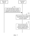
- the network device sends first-type downlink common signals to the terminal device.
- S802 The terminal device receives the first downlink common signal.
- the terminal device may detect the first-type downlink common signals, and successfully detect the first downlink common signal.
- one first-type downlink common signal corresponds to one time-frequency location for transmitting a first-type downlink common signal and one downlink common signal index.
- a downlink common signal, a downlink common signal index, and a time-frequency location of a downlink common signal may be used interchangeably on a premise that expression logic is not affected.
- the terminal device may obtain a receiving location of the system information based on the first downlink common signal.
- the terminal device obtains, based on a band in which the first downlink common signal is located, a first-type downlink common signal pattern or candidate pattern set predefined for the band.
- a meaning of the first-type downlink common signal pattern is similar to meanings of the first pattern and the second pattern in the foregoing embodiment, and details are not described herein again.
- the terminal device determines, based on second information carried in the first downlink common signal and the predefined candidate pattern set, a pattern corresponding to transmission of the first downlink common signal, namely, a first pattern pattern #1.
- the second information is used to determine a pattern of the first-type downlink common signals to which the first downlink common signal belongs. For example, if N candidate patterns are predefined, and correspond to pattern indexes #0 to #(N-1), the second information indicates the foregoing pattern index.
- the terminal device further determines a first system information transmission location based on the detected first downlink common signal.
- the first system information transmission location is one of one or more locations at which the network device may transmit the system information.
- the system information may be one of second-type downlink common signals.
- the system information may be an SIB1.
- first system information is carried on a PDSCH, and the first downlink common signal carries indication information of a frequency domain location and a time domain location of the PDSCH.
- first system information is carried on a PDSCH, and a time-frequency location and a transmission parameter of the PDSCH are indicated by using first DCI.
- the first downlink common signal carries indication information of a frequency domain location and a time domain location of the first DCI.
- the terminal device obtains, based on the first downlink common signal, the DCI for receiving and scheduling the first system information transmission location at the frequency domain location and the time domain location, to obtain a frequency domain location and a time domain location of the PDSCH carrying the first system information, namely, the first system information transmission location.
- S803 The network device sends the first system information to the terminal device.
- the first system information carries information indicating at least two frequency domain resources.
- two frequency domain resources a first frequency domain resource and a second frequency domain resource
- the first frequency domain resource and the second frequency domain resource may be two carriers, two bandwidth parts, or two other frequency units.
- the first system information carries information indicating the first frequency domain resource and the second frequency domain resource.
- the first frequency domain resource and the second frequency domain resource correspond to different uplink-downlink configurations.
- the first frequency domain resource and the second frequency domain resource may include one downlink carrier and one uplink carrier, or include one uplink BWP and one downlink BWP.
- the uplink-downlink configuration refers to a quantity and locations of downlink symbols, uplink symbols, and flexible symbols corresponding to a frequency domain resource.
- the downlink symbol is used for downlink transmission
- the uplink symbol is used for uplink transmission
- the flexible symbol is used for uplink-downlink conversion or is a symbol on which a transmission direction is not limited. It should be understood that one or two of quantities of uplink symbols, downlink symbols, and flexible symbols corresponding to the frequency domain resource may be 0.
- the uplink-downlink configuration may be represented as ⁇ xD: yS: zU ⁇ , to be specific, there are x consecutive downlink symbols, y consecutive flexible symbols, and z consecutive uplink symbols in order, where x, y, and z are integers greater than or equal to 0.
- That the first frequency domain resource and the second frequency domain resource have different uplink-downlink configurations means that quantities or locations of at least one of uplink symbols, flexible symbols, and downlink symbols corresponding to the first frequency domain resource and the second frequency domain resource are different.
- the first frequency domain resource and the second frequency domain resource in this application may be replaced with a first cell and a second cell; or may be replaced with a first carrier and a second carrier; or may be replaced with a first BWP and a second BWP.
- a carrier, a cell, and a BWP may be used interchangeably.
- the first frequency domain resource includes one downlink carrier DL carrier and one uplink carrier UL carrier
- the second frequency domain resource includes one downlink carrier and one uplink carrier.
- center frequencies of a downlink carrier and an uplink carrier included in a frequency domain resource are aligned, but widths of the downlink carrier and the uplink carrier may be different.
- the carrier may alternatively be another frequency unit, for example, a bandwidth part.
- the network device may send a downlink signal on either of the two DL carriers corresponding to the two frequency domain resources, and the terminal device may also send an uplink signal on either of the two UL carriers corresponding to the two frequency domain resources.
- the carriers corresponding to the first frequency domain resource and the carriers corresponding to the second frequency domain resource may all be in an active mode in an initial access process.
- the network device and the terminal device can send/receive information on two carriers at the same time, and it only means that the network device and the terminal device are not limited to always sending/receiving information on only one carrier.
- the two frequency domain resources have the following characteristic:
- the network device and the terminal device can quickly perform switching between two DL carriers or two UL carriers, and dynamically, quickly, and flexibly select one carrier to send/receive information.
- the two DL carriers do not overlap, or the two DL carriers have a same subcarrier spacing, or the two DL carriers have same bandwidth.
- the two UL carriers do not overlap, or the two UL carriers have a same subcarrier spacing, or the two UL carriers have same bandwidth.
- S804 The terminal device receives the first system information.
- the terminal device receives the first system information based on the detected first downlink common signal. Specifically, the terminal device determines, based on the first downlink common signal, a time-frequency location of control information for scheduling the first system information, receives the control information at the time-frequency location of the control information, where the control information indicates a receiving location of the first system information, and then receives the first system information at the location.
- the first downlink common signal is an SSB
- the first system information is an SIB1.
- the terminal device sends, on a first random access resource in a random access resource set, a random access preamble corresponding to the first random access resource.
- the random access resource set includes a random access resource on the first frequency domain resource and/or a random access resource on the second frequency domain resource.
- the random access resource set is a set of random access resources.
- a random access resource refers to a random access preamble on a random access occasion (or a random access time-frequency resource). For details, refer to the foregoing related description.
- the terminal device determines the random access resource set. For example, the terminal device determines the random access resource set based on RACH configuration information carried in the first system information.
- the RACH configuration information includes time domain location information, frequency domain location information, and code domain configuration information of a RACH occasion.
- the code domain configuration information indicates a quantity of RACH preambles that can be sent at a time-frequency location (or a RACH occasion) and specific sequence information of each preamble.
- the frequency domain location information indicates a quantity of RACH occasions at a same time domain location in a frequency domain resource and a frequency domain location of each RACH occasion.
- the time domain location information indicates a configuration period of a RACH occasion, a quantity of RACH occasions in the period, and a relative time domain location of each occasion in the period.
- the terminal device receives first random access configuration information and second random access configuration information in the first system information.
- the first random access configuration information is used to determine the random access resource on the first frequency domain resource
- the second random access configuration information is used to determine the random access resource on the second frequency domain resource.
- the first random access configuration information and the second random access configuration information are similar to the random access configuration information.
- the first random access configuration information and the second random access configuration information each include time domain location information, frequency domain location information, and code domain configuration information of a RACH occasion.
- the terminal device receives first random access configuration information in the first system information, and determines the RACH resources on the first frequency domain resource.
- the first random access configuration information includes time domain location information, frequency domain location information, and code domain configuration information of a RACH occasion. Specific meanings are the same as those described above, and details are not described herein again.
- the random access resource set includes only active random access resources, and the active random access resource means that a time domain location of the random access resource corresponds to an uplink symbol or a flexible symbol and/or the random access resource does not overlap any downlink common signal or any active downlink common signal in time domain.
- the terminal device Before determining the random access resource set, the terminal device first selects an active random access resource from random access resources on the first frequency domain resource and/or the second frequency domain resource.
- the random access resource set includes an active random access resource and an inactive random access resource. The inactive random access resource means that a time domain location of the random access resource corresponds to a downlink symbol, and/or the random access resource overlaps a downlink common signal or an active downlink common signal in time domain.
- the terminal device determines the first random access resource based on a common signal index corresponding to the detected first downlink common signal.
- the first downlink common signal herein is a first-type downlink common signal detected by the terminal device, and may be a first-type downlink common signal first detected by the terminal device, a first-type downlink common signal having maximum received signal power in one or more detected first-type downlink common signals, or a first detected first-type downlink common signal in a downlink common signal subset.
- the downlink common signal subset includes one or more first-type downlink common signals that are detected by the terminal device and whose receive power is greater than or equal to a first threshold, and the first threshold may be indicated by a first-type downlink common signal.
- the first downlink common signal is a first SSB
- the system information is an SIB 1.
- Selecting the first random access resource from the random access resource set includes: The terminal device determines a RACH resource subset based on a first SSB resource and an association relationship between an SSB resource and a RACH resource.
- the random access resource subset is a subset of the random access resource set.
- the RACH resource subset includes RACH resources on the first frequency domain resource and the second frequency domain resource.
- the RACH resource subset may include RACH resources on only one frequency domain resource.
- the terminal device needs to remove the inactive RACH resource from the RACH resource subset.
- the inactive RACH resource is not an active RACH resource, and a definition of the active RACH resource is the same as that described above.
- the terminal device selects an earliest RACH resource in time domain from the RACH resource subset, and if there are a plurality of same RACH resources in time domain, for example, a plurality of RACH occasions with different frequency domain locations, randomly selects a RACH occasion, or randomly selects a RACH sequence when one RACH occasion includes a plurality of RACH sequences.
- a spatial filtering setting used by the terminal device to send the first RACH preamble on a first RACH occasion is the same as a spatial filtering setting used by the terminal device to receive the first SSB resource.
- the network device receives, on the first random access resource, the random access preamble corresponding to the first random access resource.
- the network device detects a random access preamble on each random access resource in a first random access resource subset, and the network device obtains a random access preamble on the first random access resource through detection.
- the random access resource set of the terminal device includes random access sets separately located on at least two frequency domain resources. Because the at least two frequency domain resources correspond to different uplink-downlink configurations, the terminal device may flexibly select, based on the uplink-downlink configurations, a suitable random access resource from the random access resources corresponding to the at least two frequency domain resources to perform random access, so that a waiting delay in sending the random access preamble can be reduced, thereby reducing an access delay and improving system flexibility.
- the method further includes the following steps.
- the terminal device determines a downlink common signal resource subset, where the downlink common signal resource subset includes a downlink common signal resource on the first frequency domain resource and/or a downlink common signal resource on the second frequency domain resource.
- the downlink common signal resource subset may also be referred to as an active downlink common signal set.
- An active downlink common signal is an actually sent downlink common signal.
- the downlink common signal resource subset is a subset of a downlink common signal resource set.
- the downlink common signal resource subset includes a downlink common signal on the first frequency domain resource and a downlink common signal on the second frequency domain resource.
- the downlink common signal resource subset includes a first downlink common signal resource subset and a second downlink common signal resource subset, a resource in the first downlink common signal resource subset is located on the first frequency domain resource, and a resource in the second downlink common signal resource subset is located on the second frequency domain resource.
- the first downlink common signal resource subset is a subset of a first downlink common signal resource set (referred to as a first set).
- the first set includes one or more common signals corresponding to a first downlink common signal pattern (for example, the pattern #1).
- the first downlink common signal pattern indicates one or more downlink common signals on the first frequency domain resource, indexes of the downlink common signals, and time-frequency locations of the downlink common signals on the first frequency domain resource in one period (or one time unit).
- an index, in the first downlink common signal set, of a downlink common signal included in the first subset is indicated by first indication information.
- the second downlink common signal resource subset is a subset of a second downlink common signal resource set (referred to as a second set).
- the second set includes one or more downlink common signals corresponding to a second downlink common signal pattern (for example, a pattern #2).
- the second downlink common signal pattern indicates one or more downlink common signals on the second frequency domain resource, indexes of the downlink common signals, and time-frequency locations of the downlink common signals on the second frequency domain resource in one period (or one time unit).
- an index, in the second downlink common signal set, of a downlink common signal included in the second subset is indicated by second indication information.
- the first downlink common signal pattern may be the same as or different from the second downlink common signal pattern.
- the first indication information includes a bitmap (bitmap), each bit bit in the bitmap corresponds to one downlink common signal in the first set, and a value of the bit indicates whether the corresponding downlink common signal belongs to the first downlink common signal resource subset.
- the second indication information includes a bitmap, each bit in the bitmap corresponds to one downlink common signal in the second set, and a value of the bit indicates whether the corresponding downlink common signal belongs to the second downlink common signal resource subset.
- That the terminal device determines a downlink common signal resource subset includes:
- the terminal device receives the first indication information and the second indication information, and determines the first downlink common signal resource subset based on the first indication information.
- the first indication information and the second indication information are sent by the network device to the terminal device.
- the first indication information and the second indication information are carried in the first system information.
- the downlink common signal resource subset includes only downlink common signals on the first frequency domain resource or the second frequency domain resource.
- the downlink common signal resource set includes only a first set or a second set.
- an index, in a first downlink common signal pattern or a second downlink common signal pattern, of the downlink common signal included in the downlink common signal resource subset is indicated by first indication information or second indication information.
- the downlink common signal resource subset includes a downlink common signal on the first frequency domain resource and a downlink common signal on the second frequency domain resource.
- the downlink common signal resource subset is equal to a third downlink common signal resource subset, and the third downlink common signal resource subset is a subset of a third downlink common signal resource set (referred to as a third set).
- the third set includes one or more downlink common signals corresponding to a third downlink common signal pattern (for example, a pattern #3), and the third downlink common signal pattern indicates one or more downlink common signals on the first frequency domain resource and the second frequency domain resource, indexes of the downlink common signals, and time-frequency locations of the downlink common signals on the first frequency domain resource or the second frequency domain resource in one period (or one time unit).
- a third downlink common signal pattern indicates one or more downlink common signals on the first frequency domain resource and the second frequency domain resource, indexes of the downlink common signals, and time-frequency locations of the downlink common signals on the first frequency domain resource or the second frequency domain resource in one period (or one time unit).
- an index, in the third downlink common signal set, of the downlink common signal included in the third downlink common signal resource subset is indicated by third indication information.
- That the terminal device determines a downlink common signal resource subset includes: The terminal device receives the third indication information, and determines the third downlink common signal resource subset based on the third indication information.
- the downlink common signal resource subset is equal to the third downlink common signal resource subset.
- the method further includes: The terminal device receives downlink common signal pattern indication information.
- the downlink common signal pattern indication information indicates an index of the third downlink common signal pattern, to indicate a time domain location of each downlink common signal in the third downlink common signal set on the first frequency domain resource or the second frequency domain resource.
- a plurality of downlink common signal patterns are predefined for each band, each downlink common signal pattern corresponds to one index, and the third downlink common signal pattern is determined by obtaining the index of the third downlink common signal pattern.
- the downlink common signal pattern indication information may be carried in each first-type downlink common signal.
- one pattern is used to jointly indicate a set of downlink common signal resources on the first frequency domain resource and the second frequency domain resource, and then one piece of indication information indicates an index that is in the set and that corresponds to a common signal belonging to the downlink common signal resource subset, so that configuration flexibility can be improved.
- the random access resource set may include only active random access resources, or may include an active random access resource and an inactive random access resource.
- the downlink common signal resource subset includes the first downlink common signal resource subset and the second downlink common signal resource subset, a resource in the first downlink common signal resource subset is located on the first frequency domain resource, and a resource in the second downlink common signal resource subset is located on the second frequency domain resource.
- the association relationship includes at least one of a first association relationship, a second association relationship, a third association relationship, or a fourth association relationship, the first association relationship indicates an association relationship between a random access resource on the first frequency domain resource and the first downlink common signal resource subset, the second association relationship indicates an association relationship between a random access resource set on the second frequency domain resource and the first downlink common signal resource subset, the third association relationship indicates an association relationship between the random access resource set on the first frequency domain resource and the second downlink common signal resource subset, and the fourth association relationship indicates an association relationship between the random access resource set on the second frequency domain resource and the second downlink common signal resource subset.
- the association relationship may include at least one of a first association relationship, a second association relationship, a third association relationship, a fourth association relationship, a fifth association relationship, a sixth association relationship, a seventh association relationship, an eighth association relationship, or a ninth association relationship.
- the fifth association relationship indicates an association relationship between random access resources in two frequency domains and resources in the first downlink common signal resource subset. Random access resources in a first frequency domain and random access resources in a second frequency domain are jointly counted.
- the sixth association relationship indicates an association relationship between random access resources in the two frequency domains and resources in the second downlink common signal resource subset. Random access resources in the first frequency domain and random access resources in the second frequency domain are jointly counted.
- the seventh association relationship indicates an association relationship between random access resources on the first frequency domain resource and active common signal resources in the downlink common signal resource subset.
- the downlink common signal resource subset is the third downlink common signal resource subset.
- the eighth association relationship indicates an association relationship between random access resources on the second frequency domain resource and active common signal resources in the first downlink common signal resource set.
- the downlink common signal resource subset is the third downlink common signal resource subset.
- the ninth association relationship indicates an association relationship between random access resources in the two frequency domains and active common signal resources in the first downlink common signal resource set. Random access resources in the first frequency domain and random access resources in the second frequency domain are jointly counted, and the downlink common signal resource subset is the third downlink common signal resource subset. Downlink common signals in the third downlink common signal resource subset are jointly counted on the first frequency domain resource and the second frequency domain resource, and a corresponding index is indicated by the third downlink common signal pattern.
- the terminal device determines, based on the association relationship, a random access resource subset corresponding to a first downlink common signal resource, where the first downlink common signal resource is a resource in the downlink common signal resource subset, all random access resources in the random access resource subset belong to the random access resource set, and the random access resource subset includes the first random access resource.
- the method further includes: S807': The terminal device determines an association relationship between the random access resource set and the downlink common signal resource set, where the association relationship includes a correspondence between a downlink common signal resource in the downlink common signal resource set and a resource subset in the random access resource set.
- the terminal device may determine at least one of the following: an association relationship between the random access resource set and the downlink common signal resource set, an association relationship between the active random access resource set and the downlink common signal resource set, and an association relationship between the random access resource set and the downlink common signal resource subset, or an association relationship between the active random access resource set and the downlink common signal resource subset.
- Step S807' and step S807 may be replaced with each other.
- the terminal device may first determine the active downlink common signal resource set from the downlink common signal resource set, and then determine an association relationship between the active downlink common signal resource set and the random access resource set.
- the terminal device may determine the active random access resource set from the random access resource set, and then determine the association relationship between the downlink common signal resource set and the active random access resource set.
- the terminal device may first determine the active downlink common signal resource set from the downlink common signal resource set, determine the active random access resource set from the random access resource set, and then determine an association relationship between the active downlink common signal resource set and the active random access resource set.
- the terminal device may directly determine the association relationship between the downlink common signal resource set and the random access resource set, and when subsequently selecting a common signal and/or a random access resource for transmission, determines whether the common signal or the resource is active.
- the first downlink common signal is an SSB, and the first system information is an SIB1.
- the downlink common signal resource subset may be determined in any one of the following manners:
- the terminal device When there is an SSB on only one of the first frequency domain resource and the second frequency domain resource, for example, there is a common signal only on the first frequency domain resource, the terminal device obtains first indication information from the SIB 1.
- the first indication information indicates at least one active downlink common signal index in the first downlink common signal pattern on the first frequency domain resource, and downlink common signals corresponding to the active downlink common signal index form the active downlink common signal resource set, namely, the downlink common signal resource subset.
- the first frequency domain resource is a frequency domain resource on which the first downlink common signal is detected in the foregoing steps.
- the first frequency domain resource corresponds to a frequency domain resource on which SSB transmission detected by the terminal device in the foregoing step is located.
- the terminal device obtains the first indication information from the SIB1.
- the first indication information indicates whether SSB transmission exists on SSB resources corresponding to a plurality of SSB indexes in one SSB pattern on the first frequency domain resource, in other words, whether each SSB index is active.
- SSB resources corresponding to all active SSB indexes form the active SSB resource set.
- the SSB resources corresponding to the active SSB indexes are sorted in ascending order of the indexes in the active SSB resource set.
- the terminal device obtains first indication information and second indication information from the SIB1, determines a first active SSB resource subset based on the first indication information, where an SSB in the first active SSB resource subset belongs to the first frequency domain resource, and determines a second SSB resource subset based on the second indication information, where an SSB in the second SSB resource subset belongs to the second frequency domain resource, and the active downlink common signal resource set (namely, the downlink common signal resource subset) is a union set of the first active SSB resource subset and the second active SSB resource subset.
- the terminal device obtains the first indication information and the second indication information from the SIB 1.
- the first indication information indicates whether SSB transmission really exists on SSB resources corresponding to a plurality of SSB indexes in one SSB pattern on the first frequency domain resource, in other words, whether each SSB index is active
- the second indication information indicates whether SSB transmission really exists on SSB resources corresponding to a plurality of SSB indexes in one SSB pattern on the second frequency domain resource, in other words, whether each SSB index is active.
- SSB resources corresponding to all active SSB indexes on the first frequency domain resource and SSB resources corresponding to all active SSB indexes on the second frequency domain resource form the active SSB resource set.
- the terminal device When there are common signals on both the first frequency domain resource and the second frequency domain resource, and the common signals on the two frequency domain resources are indicated by using a same piece of indication information, the terminal device obtains third indication information from the system information SIB1, and determines the downlink common signal resource subset, namely, the downlink common signal resource subset, based on the third indication information.
- the downlink common signal resource subset is a subset of the third downlink common signal resource set corresponding to the third downlink common signal pattern, and an SSB resource set corresponding to the third downlink common signal pattern includes an SSB resource on the first frequency domain resource and an SSB resource on the second frequency domain resource.
- the terminal device obtains the third indication information from the SIB 1.
- the third indication information indicates whether SSB transmission really exists on SSB resources corresponding to a plurality of SSB indexes in one SSB pattern on the first frequency domain resource and the second frequency domain resource, in other words, whether each SSB index is active, and SSB resources corresponding to an active SSB index in the last SSB pattern form the active SSB resource set.
- the SSB resources corresponding to the active SSB indexes are sorted in ascending order of the indexes in the SSB resource set.
- the association relationship between an SSB resource and a RACH resource in step S807 or S807' may be one of the following association relationships: First: If there are SSB resources only on the first frequency domain resource, and there are RACH resources only on the first frequency domain resource, the association relationship is a first association relationship, that is, an association relationship between a RACH resource in the first frequency domain and an SSB resource in the first frequency domain.
- the association relationship between an SSB resource and a RACH resource includes a plurality of sub-association relationships, and each sub-association relationship includes SSB resources corresponding to one active SSB index and one RACH preamble set on one RACH occasion, or all RACH preamble sets on one RACH occasion, or a plurality of RACH preamble sets on a plurality of RACH occasions.
- the RACH occasion may be identified by using a RACH occasion index.
- the RACH occasion index is a manner of counting RACH occasions on the first frequency domain resource.
- a manner of counting RACH occasions on a frequency domain resource includes the following: (1) Frequency-first-time-second manner is used: RACH occasions at different frequency domain locations and one time domain location are first sorted in ascending order of the frequency domain locations, and then RACH occasions at different time domain locations are sorted in a time sequence. (2) Time-first-frequency-second manner is used: RACH occasions at different time domain locations and one frequency domain location are first sorted in a time sequence, and then RACH occasions at different frequency domain locations are sorted in ascending order of the frequency domain locations.
- a time-first-frequency-second manner is first used for one second time unit, and then second time units are sorted in a time sequence. For example, if the second time unit is a slot, RACH occasions at a plurality of frequency domain locations and a plurality of time domain locations in one slot are sorted in a time-first-frequency-second manner, and then RACH occasions in different slots are sorted in ascending order of slot indexes.
- the association relationship includes a first association relationship and a second association relationship.
- the second association relationship indicates an association relationship between a RACH resource in the second frequency domain and an SSB resource in the first frequency domain.
- the association relationship is a fifth association relationship.
- the fifth association relationship indicates an association relationship between an SSB resource on the first frequency domain resource, the RACH occasions that are jointly counted on the two frequency domain resources, and a RACH preamble on each RACH occasion.
- a method for jointly counting the RACH occasions on the two frequency domain resources includes the following: (1) Frequency-first-time-second manner: RACH occasions at different frequency domain locations on the two frequency domain resources and one time domain location are first sorted in ascending order of the frequency domain locations, and then RACH occasions at different time domain locations are sorted in a time sequence. (2) Time-first-frequency-second manner: RACH occasions at different time domain locations and one frequency domain location are first sorted in a time sequence, and then RACH occasions at different frequency domain locations are sorted in ascending order of the frequency domain locations. (3) A time-first-frequency-second manner is first used for one second time unit, and then second time units are sorted in a time sequence.
- RACH occasions at a plurality of frequency domain locations and a plurality of time domain locations in one slot are sorted in a time-first-frequency-second manner, and then RACH occasions in different slots are sorted in ascending order of slot indexes.
- RACH occasions on the first frequency domain resource are first counted and then RACH occasions on the second frequency domain resource are counted.
- RACH occasions on each frequency domain resource may be counted in a frequency-first-time-second manner, a time-first-frequency-second manner, or a combination thereof.
- all RACH occasions configured in the SIB 1 are counted, or active RACH occasions configured in the SIB 1 are counted.
- a frequency domain location of the RACH occasion is located on the first frequency domain resource or the second frequency domain resource, and a time domain location of the RACH occasion corresponds to an uplink symbol or a flexible symbol on a frequency domain resource on which the RACH occasion is located.
- the association relationship includes a first association relationship and a third association relationship.
- the association relationship includes a first association relationship, a second association relationship, a third association relationship, and a fourth association relationship.
- the association relationship includes a fifth association relationship and a six association relationship.
- the sixth association relationship indicates an association relationship between an SSB resource on the second frequency domain resource, the RACH occasions that are jointly counted on the two frequency domain resources, and a RACH preamble on each RACH occasion.
- the association relationship includes a seventh association relationship.
- the seventh association relationship indicates an association relationship between each active SSB resource in the joint SSB pattern on the two frequency domain resources and a RACH resource on the first frequency domain resource. A location and an index count of each SSB resource in one SSB pattern are determined by the SSB pattern.
- the association relationship includes a seventh association relationship and an eighth association relationship.
- the eighth association relationship indicates an association relationship between each active SSB resource in the joint SSB pattern on the two frequency domain resources and a RACH resource on the second frequency domain resource.
- the association relationship includes a ninth association relationship.
- the ninth association relationship indicates an association relationship between each active SSB resource in the joint SSB pattern on the two frequency domain resources, the jointly counted RACH occasions, and a RACH preamble on each RACH occasion.
- the method further includes:
- the second DCI is used to schedule a second PDSCH
- the second PDSCH is used to carry an RAR
- the PDCCH monitoring location in the second PDCCH monitoring location set is on the first frequency domain resource and is located in a first sub-time window
- the PDCCH monitoring location in the third PDCCH monitoring location set is on the second frequency domain resource and is located in a second sub-time window
- the first sub-time window and the second sub-time window are determined based on the first random access resource.
- the network device sends the second DCI at one or more of the PDCCH detection locations. For example, the network device selects an earliest active monitoring location in time domain to send the second DCI, so that the terminal device quickly receives the RAR.
- the terminal device detects the second downlink control information DCI at the PDCCH monitoring location in the second physical downlink control channel PDCCH monitoring location set; and/or the terminal device detects the second DCI at the PDCCH monitoring location in the third PDCCH monitoring location set.
- the terminal device directly determines a first time window.
- a length of the first time window is predefined or is indicated in the SIB 1
- a distance between a start location of the first time window and an end location of the first RACH resource is predefined or is indicated in the SIB 1.
- the terminal device detects the second DCI on the first frequency domain resource in the first time window or on the second frequency domain resource in a second time window.
- the network device sends the second DCI at one or more PDCCH detection locations of the first frequency domain resource or the second frequency domain resource, and therefore the network device may flexibly select a suitable resource from at least two frequency domain resources based on uplink-downlink configurations to send the second DCI for scheduling the random access response, so that a delay in sending the second DCI can be reduced, and system flexibility can be improved.
- the terminal device separately determines the first sub-time window and the second sub-time window, and detects the second DCI on the first frequency domain resource in the first sub-time window; and/or detects the second DCI on the second frequency domain resource in the second sub-time window.
- the following uses this case as an example for description.
- Case 1 If the terminal device supports detection of the second DCI on the two frequency domain resources, to be specific, the terminal device supports detection of the second DCI at monitoring locations in the second PDCCH monitoring location set and the third PDCCH monitoring location set, the terminal device detects the second DCI at each active detection location in the second PDCCH monitoring location on the first frequency domain resource in the first sub-time window, and detects the second DCI at each active monitoring location in the third PDCCH monitoring location set on the second frequency domain resource in the second sub-time window.
- the active monitoring location means that a symbol on which the monitoring location is located is a downlink symbol or a flexible symbol.
- Case 2 If the terminal device does not support detection of the second DCI on the two frequency domain resources, to be specific, the terminal device does not support detection of the second DCI at a monitoring location in the second PDCCH monitoring location set and an overlapping monitoring location in the third PDCCH monitoring location set, when a second monitoring location in the second PDCCH detection location set and a third monitoring location in the third PDCCH monitoring location set overlap in time domain, the terminal device determines, according to a specific rule, whether to detect the second DCI at the second monitoring location or the third monitoring location. For example, the terminal device first determines which of the second monitoring location and the third monitoring location is an active monitoring location.
- the active monitoring location means that a time domain symbol included in the PDCCH monitoring location is a downlink symbol (or a downlink symbol or a flexible symbol) on a corresponding frequency domain resource.
- a corresponding inactive monitoring location means that at least one of time domain symbols included in the PDCCH detection location is an uplink symbol or a flexible symbol (or an uplink symbol) on a corresponding frequency domain resource.
- the terminal device preferentially selects an active monitoring location to detect the second DCI. If both the second monitoring location and the third monitoring location are active monitoring locations, the terminal device may select a monitoring location according to the following criterion to detect the second DCI:
- the preset frequency domain resource may be a frequency domain resource that is predefined, is indicated by the SIB1, or directly is a frequency domain resource on which the terminal device receives the first downlink common signal in S802.
- Manner 2 A monitoring location on a frequency domain resource on which a latest active PDCCH monitoring location is located is preferentially selected for detection, so that a quantity of times the terminal device switches between two frequency domain resources is reduced.
- the terminal device does not support detection of the second DCI on the two frequency domain resources, and processing is performed based on Case 2.
- the reason is as follows: The terminal device has not completed cell access, the network device does not know a capability of the terminal device, and can consider only by default that the terminal device does not support detection of the second DCI on the two frequency domain resources, and send the second DCI based on this case. Therefore, the terminal device can detect the second DCI based on only this case.
- the second DCI is sent at the second monitoring location; or when the second monitoring location in the second PDCCH monitoring location set and the third monitoring location in the third PDCCH monitoring location set overlap in time domain, a symbol on which the second monitoring location is located is a downlink symbol or a flexible symbol, and a symbol on which the third monitoring location is located is also a downlink symbol or a flexible symbol, the second DCI is sent at a fourth monitoring location, where the fourth monitoring location is one of the second monitoring location and the third monitoring location.
- the terminal device detects the second DCI at a corresponding monitoring location.
- the second DCI is scrambled by using a random access radio network temporary identifier RA-RNTI, and a value of the RA-RNTI depends on whether a frequency domain resource on which the first random access resource is located is the first frequency domain resource or the second frequency domain resource and depends on a time-frequency location of the first random access resource in the frequency domain resource on which the first random access resource is located.
- RA-RNTI random access radio network temporary identifier
- the terminal device determines the RA-RNTI, and descrambles the second DCI based on the RA-RNTI. For example, the terminal device receives a signal at a monitoring location, demodulates and decodes the signal to obtain a bit sequence, performs descrambling based on the RA-RNTI to determine a cyclic redundancy check (Cyclic redundancy check, CRC) bit, and determines, based on the CRC bit, whether the received bit sequence is correctly received and whether the received bit sequence is sent to the terminal device.
- CRC cyclic redundancy check
- a value of the RA-RNTI is determined based on the frequency domain resource on which the first RACH resource is located and the time-frequency location of the first RACH resource in the frequency domain resource on which the first RACH resource is located. For example, for Manner 1, Manner 4, or Manner 7, the value of the RA-RNTI is determined based on only a time-frequency location of the first RACH resource on the first frequency domain resource, or is determined based on a RACH occasion index of the first RACH resource on the first frequency domain resource.
- the value of the RA-RNTI is determined depending on whether the first RACH resource is on the first frequency domain resource or the second frequency domain resource, and a time-frequency location or a RACH occasion index of the first RACH resource on the frequency domain resource. In other words, a same RACH occasion index on the first frequency domain resource and the second frequency domain resource corresponds to different RA-RNTIs.
- the value of the RA-RNTI is related to a ranking (namely, an index) of the RACH occasion of the first RACH resource in a joint counting mode.
- the terminal device receives the second PDSCH on a frequency domain resource indicated by the second DCI and a time-frequency location in the frequency domain resource, and decodes the second PDSCH. Content of the second PDSCH is parsed. If a field in the second PDSCH includes a RACH preamble index sent by the terminal device, it is considered that the field is intended for the terminal device, and subsequent steps are performed.
- the method further includes the following steps.
- the network device sends the second PDSCH to the terminal device, where the second PDSCH includes the random access response RAR, and the RAR carries indication information of a fourth frequency domain resource.
- the RAR is carried on the second PDSCH, the RAR is used to schedule a first physical uplink shared channel PUSCH, and the fourth frequency domain resource belongs to the first frequency domain resource or the second frequency domain resource.
- the terminal device receives the random access response RAR, and determines, based on the indication information of the fourth frequency domain resource, the fourth frequency domain resource used to send the first PUSCH.
- the terminal device determines an uplink timing advance TA, obtains an RAR UL grant from the RAR, and sends the first PUSCH based on the RAR UL grant.
- the terminal device sends the first PUSCH on the fourth frequency domain resource.
- the terminal device determines, based on the TA indicated in the RAR, uplink timing synchronization, namely, an advance of an uplink time axis relative to a downlink time axis, or an advance of an uplink transmission moment relative to a downlink receiving moment for a same time domain symbol.
- the terminal device sends the first PUSCH based on an indication of the RAR UL grant.
- the first PUSCH carries a message 3.
- the first PUSCH carries an ID of the terminal device.
- the network device receives the first PUSCH on the fourth frequency domain resource.
- the network device sends third DCI at a PDCCH monitoring location in a fourth PDCCH monitoring location set; and/or the network device sends third DCI at a PDCCH monitoring location in a fifth PDCCH monitoring location set.
- the third DCI is used to schedule a third PDSCH.
- the PDCCH monitoring location in the fourth PDCCH monitoring location set is on the first frequency domain resource and is located in a third sub-time window
- the PDCCH monitoring location in the fifth PDCCH monitoring location set is on the second frequency domain resource and is located in a fourth sub-time window
- the third sub-time and the fourth sub-time window are determined based on a time domain location of the first PUSCH.
- the terminal device detects the third DCI at the PDCCH monitoring location in the fourth PDCCH monitoring location set; and/or detects the third DCI at the PDCCH monitoring location in the fifth PDCCH monitoring location set.
- the terminal device directly determines a second time window applicable to the two frequency domain resources, or the third sub-time window and the fourth sub-time window respectively applicable to the first frequency domain resource and the second frequency domain resource.
- the third DCI is sent at a seventh monitoring location.
- the third DCI is detected at the fifth monitoring location; or when the fifth monitoring location in the fourth PDCCH monitoring set and the sixth monitoring location in the fifth PDCCH monitoring set overlap in time domain, a symbol on which the fifth monitoring location is located is a downlink symbol or a flexible symbol, and a symbol on which the sixth monitoring location is located is a downlink symbol or a flexible symbol, the third DCI is sent at the seventh monitoring location, where the seventh monitoring location is a preset monitoring location in the fifth monitoring location and the sixth monitoring location.
- the third DCI is scrambled by using a TC-RNTI, and the terminal device detects the third DCI based on the TC-RNTI.
- a value of the TC-RNTI is indicated by the RAR in step S810.
- the terminal device receives a third PDSCH based on an indication of the third DCI.
- the third PDSCH carries a contention resolution identifier.
- the contention resolution identifier is the same as the ID of the terminal device that is reported by the terminal device in S811, the terminal device considers that contention resolution succeeds.
- the terminal device generates feedback information HARQ-ACK based on a decoding result of the third PDSCH, and sends a second PUCCH on the sixth frequency domain resource, where the second PUCCH carries the feedback information of the third PDSCH.
- the sixth frequency domain resource belongs to the first frequency domain resource or the second frequency domain resource.
- the network device receives the feedback information HARQ-ACK of the third PDSCH on the sixth frequency domain resource.
- the feedback information includes an ACK or a NACK to respectively indicate that decoding of the third PDSCH succeeds or fails.
- FIG. 7 and FIG. 8 may be used independently or in combination.
- the implementations corresponding to FIG. 7 and FIG. 8 may alternatively be combined.
- the network device and the terminal device include corresponding hardware structures and/or software modules for performing the functions.
- a person skilled in the art should be easily aware that, with reference to the units and the method steps of the examples described in embodiments disclosed in this application, this application can be implemented in a form of hardware or a combination of hardware and computer software. Whether a function is performed by hardware or hardware driven by computer software depends on particular application scenarios and design constraints of the technical solutions.
- FIG. 9 and FIG. 10 are schematic diagrams of structures of possible communication apparatuses according to embodiments of this application. These communication apparatuses may be configured to implement functions of the terminal device or the network device in the foregoing method embodiments, and therefore can also achieve beneficial effects of the foregoing method embodiments.
- the communication apparatus may be one of the terminals 120a to 120j shown in FIG. 1 , or may be the base station 110a or 110b shown in FIG. 1 , or may be a module (for example, a chip) used in the terminal or the base station.
- a communication apparatus 900 includes a processing unit 910 and a transceiver unit 920.
- the communication apparatus 900 is configured to implement functions of the terminal device or the network device in the method embodiment shown in FIG. 7 or FIG. 8 .
- the transceiver unit 920 is configured to receive a first common signal
- the processing unit 910 is configured to determine a frequency domain resource of a second downlink common signal based on a frequency domain resource of the first downlink common signal
- the transceiver unit 920 is further configured to receive the second downlink common signal on the frequency domain resource of the second downlink common signal.
- the transceiver unit 920 is configured to send first-type downlink common signals and second-type downlink common signals to a terminal device.
- the first-type downlink common signals include one or more common signals.
- the second-type downlink common signals include one or more common signals.
- a frequency domain resource of the second-type common signal is related to a frequency domain resource of the first-type downlink common signal.
- the transceiver unit 920 is configured to: receive a first downlink common signal and system information, and send, on a first random access resource in a random access resource set, a random access preamble corresponding to the first random access resource.
- the first downlink common signal indicates a time-frequency location of control information for scheduling the system information
- the system information carries information indicating a first frequency domain resource and a second frequency domain resource
- the first frequency domain resource and the second frequency domain resource correspond to different uplink-downlink configurations.
- the random access resource set includes a random access resource on the first frequency domain resource and a random access resource on the second frequency domain resource.
- the processing unit 910 is configured to determine the first random access resource from the random access resource set and the corresponding random access preamble.
- the transceiver unit 920 is configured to send a first downlink common signal and system information to a terminal device.
- the first downlink common signal indicates a time-frequency location of control information for scheduling the system information
- the system information carries information indicating a first frequency domain resource and a second frequency domain resource
- the first frequency domain resource and the second frequency domain resource correspond to different uplink-downlink configurations.
- the processing unit 910 is configured to determine a first random access resource from a random access resource set.
- the transceiver unit 920 is further configured to receive, on the first random access resource, a random access preamble corresponding to the first random access resource.
- the first random access resource belongs to a random access resource subset, the random access resource subset is a subset of the random access resource set, and the random access resource set includes a random access resource on the first frequency domain resource and a random access resource on the second frequency domain resource.
- the transceiver unit 920 is configured to send/receive information, and the processing unit 910 is configured to perform data processing or logic processing. More detailed descriptions of the processing unit 910 and the transceiver unit 920 may be obtained by directly referring to related descriptions in the method embodiment shown in FIG. 7 or FIG. 8 . Details are not described herein again.
- a communication apparatus 1000 includes a processor 1010 and an interface circuit 1020.
- the processor 1010 and the interface circuit 1020 are coupled to each other.
- the interface circuit 1020 may be a transceiver or an input/output interface.
- the communication apparatus 1000 may further include a memory 1030, configured to store instructions to be executed by the processor 1010, store input data required by the processor 1010 to run the instructions, or store data generated after the processor 1010 runs the instructions.
- the processor 1010 is configured to implement functions of the processing unit 910
- the interface circuit 1020 is configured to implement functions of the transceiver unit 920.
- the chip of the terminal device implements functions of the terminal device in the foregoing method embodiments.
- the chip of the terminal device receives information from another module (for example, a radio frequency module or an antenna) in the terminal device.
- the information is sent by a network device to the terminal device.
- the chip of the terminal device sends information to another module (for example, a radio frequency module or an antenna) in the terminal device.
- the information is sent by the terminal device to a network device.
- the chip of the network device implements functions of the network device in the foregoing method embodiments.
- the chip of the network device receives information from another module (for example, a radio frequency module or an antenna) in the network device.
- the information is sent by a terminal device to the network device.
- the chip of the network device sends information to another module (for example, a radio frequency module or an antenna) in the network device.
- the information is sent by the network device to a terminal device.
- the processor in embodiments of this application may be a central processing unit (Central Processing Unit, CPU), or may be another general-purpose processor, a digital signal processor (Digital Signal Processor, DSP), an application-specific integrated circuit (Application-Specific Integrated Circuit, ASIC), a field programmable gate array (Field Programmable Gate Array, FPGA) or another programmable logic device, a transistor logic device, a hardware component, or any combination thereof.
- the general-purpose processor may be a microprocessor, or may be any conventional processor.
- the method steps in embodiments of this application may be implemented by hardware, or may be implemented by a processor executing software instructions.
- the software instructions may be formed by a corresponding software module, and the software module may be stored in a random access memory, a flash memory, a read-only memory, a programmable read-only memory, an erasable programmable read-only memory, an electrically erasable programmable read-only memory, a register, a hard disk, a removable hard disk, a CD-ROM, or any other form of storage medium known in the art.
- a storage medium is coupled to a processor, so that the processor can read information from the storage medium or write information into the storage medium.
- the storage medium may be a component of the processor.
- the processor and the storage medium may be located in an ASIC.
- the ASIC may be located in a network device or a terminal device.
- the processor and the storage medium may alternatively exist in the network device or the terminal device as discrete components.
- All or some of the foregoing embodiments may be implemented by software, hardware, firmware, or any combination thereof.
- the computer program product includes one or more computer programs and instructions.
- the computer may be a general-purpose computer, a dedicated computer, a computer network, a network device, user equipment, or another programmable apparatus.
- the computer programs or instructions may be stored in a computer-readable storage medium or may be transmitted from a computer-readable storage medium to another computer-readable storage medium.
- the computer programs or instructions may be wirelessly or wiredly transmitted from a website, computer, server, or data center to another website, computer, server, or data center.
- the computer-readable storage medium may be any usable medium accessible by a computer, or a data storage device, such as a server or a data center, integrating one or more usable media.
- the usable medium may be a magnetic medium, for example, a floppy disk, a hard disk, or a magnetic tape; or may be an optical medium, for example, a digital video disc; or may be a semiconductor medium, for example, a solid state disk.
- the computer-readable storage medium may be a volatile or non-volatile storage medium, or may include a volatile storage medium and a non-volatile storage medium.
- “at least one” means one or more, and "a plurality of” means two or more.
- the term “and/or” describes an association relationship between associated objects and represents that three relationships may exist.
- a and/or B may represent the following three cases: Only A exists, both A and B exist, and only B exists.
- a and B may be singular or plural.
- the character “/” usually indicates that an "or” relationship exists between associated objects.
- the character “/” indicates that a "division" relationship exists between associated objects.
Landscapes
- Engineering & Computer Science (AREA)
- Signal Processing (AREA)
- Computer Networks & Wireless Communication (AREA)
- Mobile Radio Communication Systems (AREA)
Applications Claiming Priority (1)
| Application Number | Priority Date | Filing Date | Title |
|---|---|---|---|
| PCT/CN2021/081626 WO2022193254A1 (zh) | 2021-03-18 | 2021-03-18 | 一种通信方法、装置和系统 |
Publications (2)
| Publication Number | Publication Date |
|---|---|
| EP4301065A1 true EP4301065A1 (de) | 2024-01-03 |
| EP4301065A4 EP4301065A4 (de) | 2024-05-01 |
Family
ID=83321364
Family Applications (1)
| Application Number | Title | Priority Date | Filing Date |
|---|---|---|---|
| EP21930846.7A Pending EP4301065A4 (de) | 2021-03-18 | 2021-03-18 | Kommunikationsverfahren, -vorrichtung und -system |
Country Status (4)
| Country | Link |
|---|---|
| US (1) | US20240008097A1 (de) |
| EP (1) | EP4301065A4 (de) |
| CN (1) | CN117099435A (de) |
| WO (1) | WO2022193254A1 (de) |
Families Citing this family (6)
| Publication number | Priority date | Publication date | Assignee | Title |
|---|---|---|---|---|
| WO2023167678A1 (en) * | 2022-03-03 | 2023-09-07 | Nokia Technologies Oy | User equipment autonomous resource detection for calibration |
| WO2024082349A1 (en) * | 2022-11-04 | 2024-04-25 | Lenovo (Beijing) Limited | Methods and apparatuses for resource allocation |
| CN122270979A (zh) * | 2023-11-30 | 2026-06-23 | 苹果公司 | 用于无线通信中的同步信号块(ssb)发送自适应的方法 |
| WO2025189582A1 (en) * | 2024-03-14 | 2025-09-18 | Huawei Technologies Co., Ltd. | Communication method, apparatus and system for feedback |
| WO2026137325A1 (zh) * | 2024-12-26 | 2026-07-02 | 壹泛尼提株式会社 | 唤醒信号确认的接收方法和接收装置 |
| WO2026156691A1 (en) * | 2025-01-24 | 2026-07-30 | Google Llc | Dynamic carrier selection in wireless communication systems |
Family Cites Families (11)
| Publication number | Priority date | Publication date | Assignee | Title |
|---|---|---|---|---|
| CN105430590B (zh) * | 2014-09-01 | 2018-10-23 | 电信科学技术研究院 | 一种传输以及配置突发周期业务的方法及设备 |
| WO2016175631A1 (en) * | 2015-04-30 | 2016-11-03 | Lg Electronics Inc. | Method and apparatus for configuring random access channel in short tti or contention based uplink transmission in wireless communication system |
| EP3606258A4 (de) * | 2017-03-22 | 2021-01-27 | LG Electronics Inc. | Verfahren zum senden und empfangen eines direktzugriffskanals in einem drahtloskommunikationssystem und vorrichtung dafür |
| WO2019098681A1 (ko) * | 2017-11-14 | 2019-05-23 | 엘지전자 주식회사 | 시간 분할 듀플렉싱을 지원하는 협대역 iot 시스템에서 랜덤 액세스 프리앰블을 전송하기 위한 방법 및 이를 위한 장치 |
| CN110050506B (zh) * | 2017-11-17 | 2023-08-22 | Lg电子株式会社 | 发送和接收物理随机接入信道的方法及其装置 |
| CN111436135A (zh) * | 2019-01-11 | 2020-07-21 | 华为技术有限公司 | 数据传输方法及装置 |
| CN113826437B (zh) * | 2019-03-19 | 2023-07-04 | Lg电子株式会社 | 在无线通信系统中发送和接收信号的方法及支持其的装置 |
| US20230292371A1 (en) * | 2020-08-06 | 2023-09-14 | Telefonaktiebolaget Lm Ericsson (Publ) | Rar window definition in ntn |
| US12363763B2 (en) * | 2020-08-25 | 2025-07-15 | Ofinno, Llc | Beam management for random access procedures |
| JP7847871B2 (ja) * | 2020-10-11 | 2026-04-20 | ウィルス インスティテュート オブ スタンダーズ アンド テクノロジー インコーポレイティド | 無線通信システムにおいて上りリンクチャネルを送信する方法及びそのための装置 |
| WO2022133357A1 (en) * | 2020-12-18 | 2022-06-23 | Ofinno, Llc | Random access identifier for reduced capability device |
-
2021
- 2021-03-18 WO PCT/CN2021/081626 patent/WO2022193254A1/zh not_active Ceased
- 2021-03-18 CN CN202180095701.6A patent/CN117099435A/zh active Pending
- 2021-03-18 EP EP21930846.7A patent/EP4301065A4/de active Pending
-
2023
- 2023-09-15 US US18/467,802 patent/US20240008097A1/en active Pending
Also Published As
| Publication number | Publication date |
|---|---|
| EP4301065A4 (de) | 2024-05-01 |
| US20240008097A1 (en) | 2024-01-04 |
| WO2022193254A1 (zh) | 2022-09-22 |
| CN117099435A (zh) | 2023-11-21 |
Similar Documents
| Publication | Publication Date | Title |
|---|---|---|
| EP3847865B1 (de) | Verfahren und vorrichtung für direktzugriffsvorgang | |
| US20240008097A1 (en) | Communication method, apparatus, and system | |
| US12279229B2 (en) | Method and apparatus for monitoring paging occasion in a wireless communication system | |
| US11343848B2 (en) | Method and apparatus for determining preambles and RACH occasions for 2 step random access | |
| EP4188013A1 (de) | Kommunikationsverfahren und -vorrichtung | |
| US12402202B2 (en) | Method and apparatus for handling system information request in wireless communication system | |
| US20240236939A9 (en) | Method and apparatus for paging procedure in wireless communication system | |
| US20250056629A1 (en) | Method and apparatus for small data transmission in a wireless communication system | |
| US12388513B2 (en) | Method and apparatus for radio link failure reporting in wireless communication system | |
| EP4503831A1 (de) | Erstzugangsverfahren und kommunikationsvorrichtung | |
| JP2020520593A (ja) | システム情報を取得するための方法及び装置 | |
| EP4171144A1 (de) | Verfahren und vorrichtung zur überwachung eines physikalischen downlink-steuerkanals (pdcch) und endgerät | |
| EP4311334A1 (de) | Kommunikationsverfahren und -vorrichtung | |
| US11700639B2 (en) | Method and apparatus for releasing PUSCH resources assigned for random access in wireless communication system | |
| EP4564964A1 (de) | Kommunikationsverfahren, -vorrichtung und -system | |
| KR20200097467A (ko) | 무선통신 시스템에서 2단계 랜덤 엑세스 절차를 지시하는 방법 및 장치 | |
| US20260107319A1 (en) | Method and apparatus for common channel transmission handling for network energy saving in wireless communication system | |
| US20240147352A1 (en) | Method and apparatus for si acquisition for network energy savings in wireless communication system | |
| US20250330991A1 (en) | Communication method and related apparatus | |
| US20240251406A1 (en) | Communication method and communication apparatus | |
| EP4429157A1 (de) | Erstzugangsverfahren und -vorrichtung | |
| WO2024167496A1 (en) | Dynamic random access channel resources | |
| WO2019085911A1 (en) | Window-based scheduling method, device and computer readable medium | |
| US20240305350A1 (en) | Initial access method and apparatus | |
| EP3874896B1 (de) | Verfahren und vorrichtung für bwp-vermittlung und pusch-ressourcen-overhead-verminderung für 2-schritt-rach in einem drahtloskommunikationssystem |
Legal Events
| Date | Code | Title | Description |
|---|---|---|---|
| STAA | Information on the status of an ep patent application or granted ep patent |
Free format text: STATUS: THE INTERNATIONAL PUBLICATION HAS BEEN MADE |
|
| PUAI | Public reference made under article 153(3) epc to a published international application that has entered the european phase |
Free format text: ORIGINAL CODE: 0009012 |
|
| STAA | Information on the status of an ep patent application or granted ep patent |
Free format text: STATUS: REQUEST FOR EXAMINATION WAS MADE |
|
| 17P | Request for examination filed |
Effective date: 20230928 |
|
| AK | Designated contracting states |
Kind code of ref document: A1 Designated state(s): AL AT BE BG CH CY CZ DE DK EE ES FI FR GB GR HR HU IE IS IT LI LT LU LV MC MK MT NL NO PL PT RO RS SE SI SK SM TR |
|
| A4 | Supplementary search report drawn up and despatched |
Effective date: 20240403 |
|
| RIC1 | Information provided on ipc code assigned before grant |
Ipc: H04L 5/00 20060101ALI20240326BHEP Ipc: H04W 72/04 20090101AFI20240326BHEP |
|
| DAV | Request for validation of the european patent (deleted) | ||
| DAX | Request for extension of the european patent (deleted) |