EP4301102A2 - Spritzwassergeschütztes steuergerätegehäuse - Google Patents
Spritzwassergeschütztes steuergerätegehäuse Download PDFInfo
- Publication number
- EP4301102A2 EP4301102A2 EP23181681.0A EP23181681A EP4301102A2 EP 4301102 A2 EP4301102 A2 EP 4301102A2 EP 23181681 A EP23181681 A EP 23181681A EP 4301102 A2 EP4301102 A2 EP 4301102A2
- Authority
- EP
- European Patent Office
- Prior art keywords
- exterior shell
- cooling fan
- interior area
- base
- air
- Prior art date
- Legal status (The legal status is an assumption and is not a legal conclusion. Google has not performed a legal analysis and makes no representation as to the accuracy of the status listed.)
- Pending
Links
- XLYOFNOQVPJJNP-UHFFFAOYSA-N water Substances O XLYOFNOQVPJJNP-UHFFFAOYSA-N 0.000 title claims description 17
- 238000001816 cooling Methods 0.000 claims abstract description 92
- 238000004378 air conditioning Methods 0.000 claims description 14
- 239000000428 dust Substances 0.000 claims description 9
- 238000004519 manufacturing process Methods 0.000 description 3
- 230000004075 alteration Effects 0.000 description 1
- 238000011010 flushing procedure Methods 0.000 description 1
- 238000012423 maintenance Methods 0.000 description 1
- 238000000034 method Methods 0.000 description 1
- 238000012986 modification Methods 0.000 description 1
- 230000004048 modification Effects 0.000 description 1
- 239000007921 spray Substances 0.000 description 1
Images



Classifications
-
- H—ELECTRICITY
- H05—ELECTRIC TECHNIQUES NOT OTHERWISE PROVIDED FOR
- H05K—PRINTED CIRCUITS; CASINGS OR CONSTRUCTIONAL DETAILS OF ELECTRIC APPARATUS; MANUFACTURE OF ASSEMBLAGES OF ELECTRICAL COMPONENTS
- H05K7/00—Constructional details common to different types of electric apparatus
- H05K7/20—Modifications to facilitate cooling, ventilating, or heating
- H05K7/20009—Modifications to facilitate cooling, ventilating, or heating using a gaseous coolant in electronic enclosures
- H05K7/20136—Forced ventilation, e.g. by fans
-
- B—PERFORMING OPERATIONS; TRANSPORTING
- B25—HAND TOOLS; PORTABLE POWER-DRIVEN TOOLS; MANIPULATORS
- B25J—MANIPULATORS; CHAMBERS PROVIDED WITH MANIPULATION DEVICES
- B25J13/00—Controls for manipulators
- B25J13/06—Control stands, e.g. consoles, switchboards
-
- H—ELECTRICITY
- H05—ELECTRIC TECHNIQUES NOT OTHERWISE PROVIDED FOR
- H05K—PRINTED CIRCUITS; CASINGS OR CONSTRUCTIONAL DETAILS OF ELECTRIC APPARATUS; MANUFACTURE OF ASSEMBLAGES OF ELECTRICAL COMPONENTS
- H05K5/00—Casings, cabinets or drawers for electric apparatus
- H05K5/02—Details
- H05K5/0213—Venting apertures; Constructional details thereof
- H05K5/0214—Venting apertures; Constructional details thereof with means preventing penetration of rain water or dust
-
- H—ELECTRICITY
- H05—ELECTRIC TECHNIQUES NOT OTHERWISE PROVIDED FOR
- H05K—PRINTED CIRCUITS; CASINGS OR CONSTRUCTIONAL DETAILS OF ELECTRIC APPARATUS; MANUFACTURE OF ASSEMBLAGES OF ELECTRICAL COMPONENTS
- H05K7/00—Constructional details common to different types of electric apparatus
- H05K7/14—Mounting supporting structure in casing or on frame or rack
- H05K7/1462—Mounting supporting structure in casing or on frame or rack for programmable logic controllers [PLC] for automation or industrial process control
- H05K7/1467—PLC mounted in a cabinet or chassis
-
- H—ELECTRICITY
- H05—ELECTRIC TECHNIQUES NOT OTHERWISE PROVIDED FOR
- H05K—PRINTED CIRCUITS; CASINGS OR CONSTRUCTIONAL DETAILS OF ELECTRIC APPARATUS; MANUFACTURE OF ASSEMBLAGES OF ELECTRICAL COMPONENTS
- H05K7/00—Constructional details common to different types of electric apparatus
- H05K7/20—Modifications to facilitate cooling, ventilating, or heating
- H05K7/20009—Modifications to facilitate cooling, ventilating, or heating using a gaseous coolant in electronic enclosures
- H05K7/20136—Forced ventilation, e.g. by fans
- H05K7/20145—Means for directing air flow, e.g. ducts, deflectors, plenum or guides
-
- H—ELECTRICITY
- H05—ELECTRIC TECHNIQUES NOT OTHERWISE PROVIDED FOR
- H05K—PRINTED CIRCUITS; CASINGS OR CONSTRUCTIONAL DETAILS OF ELECTRIC APPARATUS; MANUFACTURE OF ASSEMBLAGES OF ELECTRICAL COMPONENTS
- H05K7/00—Constructional details common to different types of electric apparatus
- H05K7/14—Mounting supporting structure in casing or on frame or rack
- H05K7/1462—Mounting supporting structure in casing or on frame or rack for programmable logic controllers [PLC] for automation or industrial process control
Definitions
- the present disclosure relates to an enclosure designed to enclose and protect a robot controller from water in a washdown environment and/or protect a robot controller from dust in a dusty environment while also providing proper cooling for the enclosed robot controller.
- Robot controller utilizes a separate robot controller to run the robot.
- the separate robot controller is where electronics for controlling movement of the industrial robot and for sensing and vision of the industrial robot, among other things, occurs.
- the present disclosure addresses the above-described problem and provides protection to the robot controller in washdown and dusty environments without requiring alteration to the controller itself.
- a system configured to enclose one or more robot controllers.
- a system comprises a base and an exterior shell configured to couple with the base, the exterior shell defining an interior area sized to enclose a robot controller of an industrial machine.
- the system further comprises a first cooling fan and a second cooling fan.
- the first cooling fan is positioned on the exterior shell, wherein the first cooling fan is configured to draw air into the interior area of the exterior shell and the first cooling fan comprises a baffle positioned on the exterior shell that is configured to prevent water from entering the interior area of the exterior shell at the first cooling fan.
- the second cooling fan is positioned on the exterior shell, wherein the second cooling fan is configured to expel at least one of air or moisture from the interior area of the exterior shell and the second cooling fan comprises a baffle positioned on the exterior shell that is configured to prevent water from entering the interior area of the exterior shell at the second cooling fan.
- At least one of the first cooling fan or the second cooling fan further comprises a filter configured to prevent dust from entering the interior area of the disclosure.
- the present disclosure further provides a system configured to enclose a plurality of robot controllers for one or more industrial machines.
- the system comprises a plurality of enclosures stacked on top of each other, wherein each enclosure comprises a base and an exterior shell configured to couple with the base, the exterior shell defining an interior area sized to enclose a robot controller.
- Each enclosure further comprises a first cooling fan and a second cooling fan.
- the first cooling fan is positioned on the exterior shell, wherein the first cooling fan is configured to draw air into the interior area of the exterior shell and the first cooling fan comprises a baffle positioned on the exterior shell that is configured to prevent water from entering the interior area of the exterior shell at the first cooling fan.
- the second cooling fan is positioned on the exterior shell, wherein the second cooling fan is configured to expel at least one of air or moisture from the interior area of the exterior shell and the second cooling fan comprises a baffle positioned on the exterior shell that is configured to prevent water from entering the interior area of the exterior shell at the second cooling fan.
- At least one of the first cooling fan or the second cooling fan further comprises a filter configured to prevent dust from entering the interior area of the disclosure.
- the filter may be removable and cleanable.
- the disclosure further provides another system that is configured to enclose one or more robot controllers.
- the system comprises a base; an exterior shell configured to couple with the base, the exterior shell defining an interior area sized to enclose a robot controller of an industrial machine; and an air conditioning unit positioned on the exterior shell, wherein the air conditioning unit is configured to create a circular airflow at least partially around the robot controller position in the interior area of the exterior shell.
- Figure 1a illustrates a first perspective view
- Figure 1b illustrates a second perspective view of a first enclosure 102 for a first robot controller and a second enclosure 104 for a second robot controller.
- the first enclosure 102 is stacked on top of the second enclosure 104 using multiple side plates 105.
- more than two enclosures may be stacked on top of each other to preserve production floor space.
- an enclosure 102, 104 for a robot controller to keep a robot controller within the enclosure dry in a washdown environment or dust-free in a dusty environment.
- a robot controller To keep the robot controller dry, first, water should be kept from entering into an interior of the enclosure during the washdown process, and second, any moisture that seeps into the interior of the enclosure or that enters the enclosure via humid air should be eliminated. Similarly, to keep the robot controller dust-free, dust should be kept from entering the interior of the enclosure from the dusty environment.
- implementations of the enclosure 102 may include a first cooling fan 106 positioned as an air inlet fan on an exterior shell 108 of the enclosure 102 and a second cooling fan 110 positioned as an air exhaust fan on the exterior shell 108 of the enclosure 102.
- the exterior shell 108 defines an interior area that is sized to enclose a robot controller of an industrial machine. In some implementations, the interior area of the exterior shell 108 may define approximately 26,900 cubic inches. However, one of skill in the art will appreciate that the exterior shell may be sized to accommodate any sized component of a robot controller and an airflow around the robot controller.
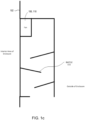
- the first cooling fan 106 and the second cooling fan 110 may include one or more baffles 111 that are mounted to the exterior shell 108.
- the baffles at the first cooling fan 106 and the second cooling fan 110 prevent water from entering the interior area of the enclosure 102 through the first cooling fan 106 and/or the second cooling fan 110.
- Figure 1c illustrates a cut-away side view of a fan 106, 110 and associated baffles 111 positioned on the exterior shell 108.
- the first cooling fan 106 may include a removable filter that prevents dust from entering the interior area of the disclosure at the first cooling fan 106.
- the second cooling fan 110 may also include a removable filter that prevents dust from entering the interior area of the disclosure at the second cooling fan 110.
- the removable filter of the fans may be cleanable for reuse.
- the first cooling fan 106 and the second cooling fan 110 are configured to move between 155 and 500 cubic feet per minute (CFM). Further, in some implementations, the first cooling fan 106 is positioned on the exterior shell 108 adjacent to or near a base 118 of the interior of the enclosure 102 to improve airflow through the interior of the enclosure 102. Further, in some implementations, the second cooling fan 110 may be positioned on the exterior shell 108 adjacent to or near a top of the exterior shell 108 to assist in airflow and expelling at least one of water or moisture from the interior of the enclosure 102.
- CFM cubic feet per minute
- the exterior shell 108 may additionally include access panels 112, provided with seals, that provide access to the interior area of the enclosure 102 without having to remove the exterior shell 108 from the base 118.
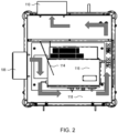
- the interior area of the enclosure 102 also includes a set of baffles 114.
- the baffles 114 positioned in the interior of the enclosure 102 assist in redirecting airflow though the interior of the enclosure 102, as explained in more detail below.
- Humid air and seeping moisture are controlled within the interior area of the enclosure 102 by having a constant airflow within the interior area of the enclosure 102 that is sufficient to expel the humid air and moisture from the interior area, cause the moisture in the interior area to evaporate, and/or prevent humid air from condensing in the interior area. Accordingly, the airflow through the enclosure 102 should be maintained in order to protect the robot controller.
- One or more baffles 114 then direct the airflow around an exterior of the robot controller 116 and through the interior area of the enclosure 102 until the airflow exits the interior of the enclosure at the second cooling fan 110 positioned as an air exhaust.
- some of the one or more baffles 114 are mounted to the base 118 of the enclosure.
- at least some of the one or more baffles 114 may be mounted on other portions of the enclosure 102.
- the implementations illustrated in Fig. 2 includes two fans, in other implementations, the enclosure may utilize one fan or more than two fans.
- the airflow within the interior area of the enclosure 102 accommodates one or more cooling fans 120 that are present on the robot controller 116 itself. For example, a direct air path from the first cooling fan 106 positioned as the inlet fan to second cooling fan 110 positioned as the exhaust fan is avoided. If a direct air path were to exist between the first and second cooling fans 106, 110, the hot air generated by the robot controller 116 would not be flushed out of the enclosure 102.
- the baffles 114 prevent a direct air path between the first and second cooling fans 106, 110 by directing air from the first cooling fan 106 away from the second cooling fan 110. Additionally, in some implementations, the baffles 114 direct the airflow around the interior of the enclosure 102 as shown in Fig. 2 to flow at least partially around the robot controller 116 and to provide a circular flushing of air within the interior area of the enclosure 102.
- an air conditioning unit is positioned on the enclosure 102. Similar to the cooling fans, the air conditioning unit may include baffles to prevent water from entering the interior area of the enclosure 102 at the air conditioning unit and/or the air conditioning unit may include a filter to prevent dust from entering the interior area of the enclosure 102 at the air conditioning unit.
- an air inlet of the air condition and an air outlet of the air conditioning unit are positioned on the enclosure 102 to create a circular airflow in the interior area of the enclosure 102 at least partially around a robot controller positioned in the interior area of the enclosure 102, similar to the airflow described above that is generated by the first and second fans 106, 110.
- baffles 114 within the interior area of the enclosure 102 prevent airflow directly between the air inlet and air outlet of the air conditioning unit and direct the airflow around the robot controller.
- the air inlet of the air conditioner is positioned near a top of the enclosure 102 and the air outlet of the air conditioning is positioned near a bottom of the enclosure 102 near a base 118 to assist in generating the circular airflow in the interior area of the enclosure 102.
- enclosures 102, 104 of the present disclosure are equipped with a removable exterior shell 108 that can be safely lifted off a base 118. With the exterior shell 108 removed from the base 118, installers can use recommended lifting eyes 122 and an overhead crane to safely put the robot controller 116 in place on a mounting plate 124.
- the shell 108 is also equipped with one or more configurable access panels 112 to allow access to the robot controller 116 once the exterior shell 108 is installed.
- the access panels 112 provide access to wiring points and maintenance areas in the interior of the enclosure 102, for use in situations such as if a cooling fan 120 on the robot controller 116 needs to be replaced.
- two or more enclosures 102, 104 can be stacked one on top of the other by using side plates 105.
- multiple enclosures are utilized when two or more robots operate within the same cell at an industrial facility.
- Figures 1-4 illustrate a system including one or more enclosures 102 that provide an exterior shell 108 defining an interior area that is configured to cover and protect a robot controller.
- This exterior shell 108 is designed so that it can be lifted on and off of a base 118 such that a mounting of the heavy robot controller can be done easily and safely.
- an inlet fan 106 and an outlet fan 110 positioned on the exterior shell provide air circulation through the interior area of the enclosure 102 around the robot controller.
- an air inlet and an air outlet of an air conditioning unit positioned on the exterior shell provide air circulation through the interior area of the enclosure 102 and around the robot controller.
- baffles 114 within the interior area of the enclosure 102 are mounted strategically to ensure that hot air generated by the robot controller is flushed from the interior area of the enclosure 102, as well as moist humid air or water spray that may enter the interior area of the enclosure 102 during a washdown.
Landscapes
- Engineering & Computer Science (AREA)
- Microelectronics & Electronic Packaging (AREA)
- Physics & Mathematics (AREA)
- Thermal Sciences (AREA)
- Robotics (AREA)
- Mechanical Engineering (AREA)
- Automation & Control Theory (AREA)
- Manipulator (AREA)
Applications Claiming Priority (2)
| Application Number | Priority Date | Filing Date | Title |
|---|---|---|---|
| US202263357200P | 2022-06-30 | 2022-06-30 | |
| US18/208,402 US20240008213A1 (en) | 2022-06-30 | 2023-06-12 | Washdown controller enclosure |
Publications (2)
| Publication Number | Publication Date |
|---|---|
| EP4301102A2 true EP4301102A2 (de) | 2024-01-03 |
| EP4301102A3 EP4301102A3 (de) | 2024-03-20 |
Family
ID=87002981
Family Applications (1)
| Application Number | Title | Priority Date | Filing Date |
|---|---|---|---|
| EP23181681.0A Pending EP4301102A3 (de) | 2022-06-30 | 2023-06-27 | Spritzwassergeschütztes steuergerätegehäuse |
Country Status (2)
| Country | Link |
|---|---|
| US (1) | US20240008213A1 (de) |
| EP (1) | EP4301102A3 (de) |
Family Cites Families (11)
| Publication number | Priority date | Publication date | Assignee | Title |
|---|---|---|---|---|
| US6613130B2 (en) * | 1999-07-09 | 2003-09-02 | G.E.N. Industries Corp | Filtering system for removing combustion gases from an airflow |
| US6643130B1 (en) * | 2002-07-08 | 2003-11-04 | Demarchis John A. | Wash down filtered fan apparatus |
| US20050108996A1 (en) * | 2003-11-26 | 2005-05-26 | Latham Steven R. | Filter system for an electronic equipment enclosure |
| US7762373B2 (en) * | 2005-05-25 | 2010-07-27 | Sony Corporation | Fan noise control apparatus |
| TWM370767U (en) * | 2009-06-19 | 2009-12-11 | fu-zhi Huang | Modulized computer |
| EP2503257B9 (de) * | 2011-03-22 | 2014-06-04 | Erwin Gasser | Shelter |
| CN208842243U (zh) * | 2018-06-20 | 2019-05-10 | 武汉万实新能源科技股份有限公司 | 充电桩 |
| US11660573B2 (en) * | 2018-12-31 | 2023-05-30 | Ice Qube, Inc. | Filtered fan apparatus |
| FR3106283B1 (fr) * | 2020-01-21 | 2022-08-12 | Jean Angelidis | dispositif de désodorisation et/ou de purification d'air |
| CN112040694A (zh) * | 2020-09-08 | 2020-12-04 | 珠海横琴新区辉腾电子科技有限公司 | 一种计算机网络用户外机柜 |
| CN113692184A (zh) * | 2021-08-12 | 2021-11-23 | 江苏润和智融科技有限公司 | 一种数据采集的室内外设备 |
-
2023
- 2023-06-12 US US18/208,402 patent/US20240008213A1/en active Pending
- 2023-06-27 EP EP23181681.0A patent/EP4301102A3/de active Pending
Also Published As
| Publication number | Publication date |
|---|---|
| EP4301102A3 (de) | 2024-03-20 |
| US20240008213A1 (en) | 2024-01-04 |
Similar Documents
| Publication | Publication Date | Title |
|---|---|---|
| KR960004224B1 (ko) | 연결식 클리인공간장치 | |
| JP3309416B2 (ja) | 連結式クリーン空間装置 | |
| EP3082388B1 (de) | Temperaturgeregelter schrank | |
| US6869457B2 (en) | Clean room for semiconductor device | |
| JP2003166729A (ja) | 通信・情報処理機器室等の空調システム | |
| US20220258362A1 (en) | Control device for robot | |
| JPS5950369B2 (ja) | 清浄空気領域形成装置 | |
| EP4301102A2 (de) | Spritzwassergeschütztes steuergerätegehäuse | |
| KR20180024143A (ko) | 전장함의 환기 및 냉각 제어 시스템 | |
| JP3884570B2 (ja) | 基板処理装置 | |
| JP4899939B2 (ja) | クリーンルーム用ストッカ | |
| JP2001358487A (ja) | 制御盤の冷却装置 | |
| KR20160113289A (ko) | 패키지 수납형 엔진 발전기 | |
| CN110621942A (zh) | 空调机 | |
| JP4003637B2 (ja) | 原子力発電所タービン建屋の給排気設備 | |
| JP7737040B2 (ja) | 換気装置 | |
| KR102397274B1 (ko) | 친환경 폐열 회수용 에너지 절감장치 | |
| JP3855194B2 (ja) | クリーンルームの空調システム | |
| CN218276265U (zh) | 电机机座 | |
| JP2508358B2 (ja) | 電気装備品収納装置 | |
| CN215343553U (zh) | 电控箱 | |
| JP4712825B2 (ja) | ブロワーボックス及び該ボックスの敷設方法 | |
| CN220857411U (zh) | 一种电气柜干燥装置 | |
| CN222673654U (zh) | 一种机械设备专用电器柜 | |
| JP2007178065A (ja) | クリーンルーム用還気装置 |
Legal Events
| Date | Code | Title | Description |
|---|---|---|---|
| PUAI | Public reference made under article 153(3) epc to a published international application that has entered the european phase |
Free format text: ORIGINAL CODE: 0009012 |
|
| STAA | Information on the status of an ep patent application or granted ep patent |
Free format text: STATUS: THE APPLICATION HAS BEEN PUBLISHED |
|
| AK | Designated contracting states |
Kind code of ref document: A2 Designated state(s): AL AT BE BG CH CY CZ DE DK EE ES FI FR GB GR HR HU IE IS IT LI LT LU LV MC ME MK MT NL NO PL PT RO RS SE SI SK SM TR |
|
| PUAL | Search report despatched |
Free format text: ORIGINAL CODE: 0009013 |
|
| AK | Designated contracting states |
Kind code of ref document: A3 Designated state(s): AL AT BE BG CH CY CZ DE DK EE ES FI FR GB GR HR HU IE IS IT LI LT LU LV MC ME MK MT NL NO PL PT RO RS SE SI SK SM TR |
|
| RIC1 | Information provided on ipc code assigned before grant |
Ipc: H05K 7/20 20060101ALI20240213BHEP Ipc: H05K 5/02 20060101AFI20240213BHEP |
|
| STAA | Information on the status of an ep patent application or granted ep patent |
Free format text: STATUS: REQUEST FOR EXAMINATION WAS MADE |
|
| 17P | Request for examination filed |
Effective date: 20240917 |
|
| RBV | Designated contracting states (corrected) |
Designated state(s): AL AT BE BG CH CY CZ DE DK EE ES FI FR GB GR HR HU IE IS IT LI LT LU LV MC ME MK MT NL NO PL PT RO RS SE SI SK SM TR |