EP4301123B1 - Werkzeugwechselsystem fuer bodenbearbeitungsmaschinen - Google Patents
Werkzeugwechselsystem fuer bodenbearbeitungsmaschinen Download PDFInfo
- Publication number
- EP4301123B1 EP4301123B1 EP21759324.3A EP21759324A EP4301123B1 EP 4301123 B1 EP4301123 B1 EP 4301123B1 EP 21759324 A EP21759324 A EP 21759324A EP 4301123 B1 EP4301123 B1 EP 4301123B1
- Authority
- EP
- European Patent Office
- Prior art keywords
- tool
- soil
- clamping lever
- carrier
- lever
- Prior art date
- Legal status (The legal status is an assumption and is not a legal conclusion. Google has not performed a legal analysis and makes no representation as to the accuracy of the status listed.)
- Active
Links
Images






Classifications
-
- A—HUMAN NECESSITIES
- A01—AGRICULTURE; FORESTRY; ANIMAL HUSBANDRY; HUNTING; TRAPPING; FISHING
- A01B—SOIL WORKING IN AGRICULTURE OR FORESTRY; PARTS, DETAILS, OR ACCESSORIES OF AGRICULTURAL MACHINES OR IMPLEMENTS, IN GENERAL
- A01B35/00—Other machines for working soil
- A01B35/20—Tools; Details
- A01B35/22—Non-rotating tools; Resilient or flexible mounting of rigid tools
- A01B35/225—Non-rotating tools; Resilient or flexible mounting of rigid tools the tools being adapted to allow the chisel point to be easily fitted or removed from the shank
-
- A—HUMAN NECESSITIES
- A01—AGRICULTURE; FORESTRY; ANIMAL HUSBANDRY; HUNTING; TRAPPING; FISHING
- A01B—SOIL WORKING IN AGRICULTURE OR FORESTRY; PARTS, DETAILS, OR ACCESSORIES OF AGRICULTURAL MACHINES OR IMPLEMENTS, IN GENERAL
- A01B15/00—Elements, tools, or details of ploughs
- A01B15/02—Plough blades; Fixing the blades
- A01B15/04—Shares
- A01B15/06—Interchangeable or adjustable shares
Definitions
- the invention relates to a tool changing system for soil tillage machines according to the preamble of patent claim 1, a soil tillage tool according to the preamble of patent claim 14 and a method for assembling a soil tillage tool according to the preamble of patent claim 15.
- Agricultural tillage machines such as agricultural hoeing machines, can be equipped with a tool-changing system designed to simplify and/or accelerate the change of tillage tools used.
- Tillage tools used in hoeing technology include, for example, share plates, which are subject to comparatively high wear during use, necessitating regular tool changes.
- agricultural tillage machines are typically used with different tillage tools, each adapted to a specific tillage operation, a specific soil type, and/or the requirements of a specific crop.
- quick-change tool systems are often used, in which the tillage tool is screwed to the tool carrier using a screw.
- the screw head is located on the underside of the tillage tool, so that it becomes clogged with soil and plant residue during the tillage process, which often makes subsequent loosening of the screw problematic.
- the fastening screws used often break, so that the tillage tool detaches from the tool carrier during the tillage process, usually unnoticed by the machine operator.
- a corresponding tool changing system in which the tool is fastened by screws, is known, for example, from the publication US$4,799,555 Further tool changing systems are described in the documents EP 1 723 841 A1 , DE 23 65 914 A1 and US 7 255 179 B2 revealed.
- the object underlying the invention is therefore to simplify and/or accelerate the change of soil cultivation tools on an agricultural soil cultivation machine.
- the locking device of the tool changing system comprises a clamping lever by means of which the engagement mechanism can be locked.
- the soil cultivation tool can be, for example, a coulter plate.
- the tool changing system is designed, for example, for use with an agricultural hoe.
- the tool carrier preferably has an elongated basic shape.
- the tool carrier can be a one-piece component.
- the tool carrier is a support stem or a support rod.
- the tool carrier is preferably made of metal or a metal alloy.
- the clamping lever preferably has a elongated basic shape.
- the clamping lever can be a one-piece component.
- the clamping lever is preferably made of metal or a metal alloy.
- the clamping lever has a locking portion that can be inserted into a lever receiving recess of the engagement mechanism.
- the lever receiving recess is preferably arranged in the soil cultivation tool. Inserting the locking portion of the clamping lever into the lever receiving recess preferably pre-locks the engagement mechanism.
- the clamping lever is preferably moved into a locking position, wherein moving the clamping lever into a locking position is accompanied by clamping the soil cultivation tool to the tool carrier.
- the lever receiving recess is preferably arranged in a rear, free area of the soil cultivation tool.
- the lever receiving recess is accessible from the rear of the soil cultivation tool, so that the clamping lever can be easily inserted from the rear and above. This allows for safe and easy assembly of the tillage tool, as no assembly operations need to be carried out on the underside of the tillage tool.
- the tillage tool and the tool carrier can be clamped together by means of the clamping lever.
- the tillage tool When clamping the tillage tool and the tool carrier, the tillage tool is pushed or pulled backward by the clamping lever.
- the tillage tool and the tool carrier can initially perform a relative movement to one another during clamping. By performing the relative movement of the tillage tool and the tool carrier, they are positioned relative to one another and pre-locked to one another.
- the clamping of the tillage tool and the tool carrier This is preferably achieved by moving the clamping lever into a locking position after inserting the clamping lever into the lever receiving recess.
- the clamping lever must be pivoted upwards, for example, after inserting the clamping lever into the lever receiving recess. In the locking position, the clamping lever exerts a clamping force on the tillage tool and/or the tool carrier, via which the tillage tool and the tool carrier are fastened to one another.
- the engagement mechanism can allow a release movement of the tillage tool and/or the tool carrier, thereby disengaging the engagement between the tillage tool and the tool carrier.
- the clamping force generated by the clamping lever after the clamping lever is moved into the locking position acts opposite to the release direction, so that a release movement of the tillage tool and/or the tool carrier is prevented by the clamping lever.
- the clamping lever has a tool contact area which is designed to be pressed against the contour of the lever receiving recess when the soil cultivation tool and the tool carrier are clamped together.
- the tool contact area is preferably located in the locking section of the clamping lever, which is inserted into the lever receiving recess of the engagement mechanism. When the clamping lever is moved into the locking position and/or in the locking position, the tool contact area of the clamping lever is in contact with the contour of the lever receiving recess.
- the clamping lever has a carrier contact area which is designed to be pressed against a lever guide area of the tool carrier when clamping the soil cultivation tool and the tool carrier together.
- the carrier contact area of the clamping lever is preferably in contact with the lever guide area of the tool carrier.
- a tool changing system is advantageous in which the carrier contact area of the clamping lever has a convexly curved contact surface.
- the carrier contact area of the clamping lever preferably has a convex rounded portion.
- the lever guide area of the tool carrier can have a concavely curved contact surface.
- the lever guide area of the tool carrier has a concave rounded portion.
- the convexly curved contact surface on the clamping lever and the concavely curved contact surface on the tool carrier preferably have matching radii.
- the convexly curved contact surface on the clamping lever and the concavely curved contact surface on the tool carrier preferably jointly form an open plain bearing for the clamping lever.
- the contact surfaces in the carrier contact area and in the lever guide area can be spherical, at least in sections.
- a tool changing system is advantageous in which the carrier contact area and the lever guide area together form a pivot bearing for the clamping lever, which allows a guided rotational movement of the clamping lever over a pivot angle range. Executing the rotational movement of the clamping lever over the pivot angle range is preferably necessary to move the clamping lever into the locking position after insertion into the lever receiving recess.
- the tool changing system according to the invention is further advantageously developed in that the clamping lever is configured to be elastically deformed when the soil cultivation tool and the tool carrier are clamped together.
- the clamping lever is elastically bent when the soil cultivation tool and the tool carrier are clamped together.
- the clamping lever can be a spring bar, for example.
- the clamping lever is elastically deformed, in particular elastically bent, when moved into the locking position.
- the locking device has a holding member designed to hold the clamping lever in a locking position in which the soil tillage tool and the tool carrier are clamped together by means of the clamping lever.
- the pivot bearing is preferably arranged away from the holding member, thus creating a favorable leverage ratio.
- the clamping lever can therefore be moved into the locked position either by hand or with an additional tool.
- the retaining link prevents the clamped clamping lever from snapping back.
- the retaining link can be a ring-shaped body, for example.
- the tool carrier can have a support for the retaining link, which prevents the retaining link from falling down uncontrollably if the retaining link is not secured by the clamping lever.
- the retaining link can also be a linch pin.
- the retaining link can be moved into an auxiliary assembly position in which the clamping lever is removably attached to the retaining link so that the clamping lever does not get lost when changing the soil cultivation tool. In the auxiliary assembly position, the clamping lever can hang loosely from the retaining link.
- the clamping lever is configured to be elastically deformed in the locking position, preferably extending along a curved edge of the tool carrier in the locking position.
- the curved edge of the tool carrier, along which the clamping lever extends in the locking position is preferably convex and/or a rear end edge of the tool carrier.
- the space between the curved edge of the tool carrier and the clamping lever can be filled with an elastically deformable material when the clamping lever is in the locked position.
- the elastically deformable material can be attached, for example, to the curved edge of the tool carrier and/or to the clamping lever, e.g. glued.
- the elastically deformable material can be foam rubber, for example. The elastically deformable material merely fills the gap elastically, but does not perform a closing and/or locking function.
- the elastically deformable material is located in an area protected from earth currents, thus preventing the elastically deformable material from being detached from the clamping lever and/or the tool carrier by the earth current. Due to the elastic deformability of the material, reliable and easy clamping and releasing of the clamping lever is still possible.
- the tool changing system according to the invention is further advantageously developed in that the engagement mechanism has one or more engagement bodies, each engagement body being configured to engage in a receiving recess of the engagement mechanism.
- the one or more engagement bodies are preferably located on the underside of the tool carrier.
- the one or more engagement bodies are preferably integral components of the tool carrier.
- the one or more receiving recesses are preferably located in the soil cultivation tool.
- the one or more engagement bodies preferably protrude only slightly from the one or more receiving recesses, so that the one or more engagement bodies are protected from wear due to contact with the earth current.
- plate-shaped soil cultivation tools can have different material thicknesses. By locking via one or more engagement bodies, the compatibility of the soil cultivation tool and the tool carrier is not dependent on the material thickness of the soil cultivation tool. This results in a universal and flexibly applicable Engagement mechanism which is independent of the plate thickness of a plate-shaped soil tillage tool.
- an engagement body of the engagement mechanism is configured to engage the lever-receiving recess, into which the locking portion of the clamping lever can also be inserted.
- the lever-receiving recess thus accommodates both an engagement body and the locking portion of the clamping lever.
- the lever-receiving recess thus serves to establish an engagement state between the soil cultivation tool and the tool carrier and to clamp the soil cultivation tool and tool carrier to one another.
- the one or more engagement bodies have a contact surface that is configured to be pressed against a contact section of the inner contour of a receiving recess when the soil cultivation tool and the tool carrier are clamped together.
- the inner contour of the receiving recess thus serves as a counterbearing when the soil cultivation tool and the tool carrier are clamped together by means of the clamping lever.
- the contact surface of the one or more engagement bodies and the contact section of the inner contour of the one or more receiving recesses have corresponding chamfers.
- the chamfers wedge the soil tillage tool and the tool carrier into one another when clamped by means of the clamping lever.
- a virtually play-free fit of the soil tillage tool on the tool carrier is achieved.
- the clamping lever ensures that the play-free fit is maintained during a tillage operation, so that the soil tillage tool cannot tilt and/or twist even under the influence of soil tillage forces.
- the engagement bodies preferably have matching or differing chamfer angles.
- the inner contours of the receiving recesses have identical or different chamfer angles.
- the chamfer angle at the chamfers of the engagement bodies and the chamfer angle at the chamfers of the inner contours of the receiving recesses preferably ranges between 30 degrees and 60 degrees, for example, 45 degrees.
- the tool carrier may also have markings for adjusting the position of the tillage tool and/or the working depth. These markings may form a scale for adjusting the height. These markings eliminate the need for a grid in the edge area of the tool carrier.
- the clamping lever is designed as a bent wire part.
- the clamping lever is designed as a spring clip.
- the clamping lever can be U-shaped, so that two open ends of the bent wire part are directly opposite one another and/or a loop is formed at the closed end of the bent wire part.
- the contour of the clamping lever can be mirror-symmetrical, so that it is formed by two wire ends running symmetrically, in particular directly next to one another.
- the clamping lever has an open shape, so that the risk of adhering soil material and entangled plant residue is particularly reduced.
- the tool carrier can have, in particular on its rear side, a preferably hook-shaped holding member which is designed to hold the clamping lever in a locked position in which the soil cultivation tool and the tool carrier are clamped together by means of the clamping lever.
- the tensioning lever can engage behind the holding member in the locking position, in particular by means of the loop at its closed end.
- the object underlying the invention is further achieved according to the subject matter of claim 14 by a soil cultivation tool for a tool changing system.
- the tool changing system can be designed according to one of the above embodiments. It is provided that the soil cultivation tool is designed to be moved through soil.
- the soil tillage tool has at least one receiving recess by means of which the soil tillage tool is designed to form an engagement mechanism with a tool carrier, so that the soil tillage tool can be arranged on the tool carrier.
- the soil tillage tool has a lever receiving recess into which a clamping lever can be inserted. The lever receiving recess can accommodate a locking section of a clamping lever.
- the soil tillage tool can be further developed by features which relate to the soil tillage tool and which were explained in connection with the above embodiments of the tool changing system.
- the object underlying the invention is further achieved by a method of the type mentioned above according to the subject matter of claim 15, wherein the engagement mechanism is locked within the scope of the method according to the invention by means of a clamping lever of a locking device of the tool changing system.
- the method according to the invention is preferably carried out using a tool changing system according to one of the embodiments described above, so that with regard to the advantages and modifications of the method according to the invention, reference is made to the advantages and modifications of the tool changing system according to the invention.
- the Fig. 1 shows a tool changing system 10 for an agricultural soil tillage machine.
- the tool changing system 10 comprises a Soil cultivation tool 12, which engages with a tool carrier 14.
- the soil cultivation tool 12 can, for example, be a coulter plate, which is moved through the soil at a shallow depth during soil cultivation.
- the soil cultivation tool 12 has a V-shaped plate and is designed as a one-piece metal body.
- the tool carrier 14 has an elongated basic shape and is designed as a one-piece metal support rod.
- the soil tillage tool 12 and the tool carrier 14 can be clamped together by means of a clamping lever 18.
- the Fig. 1 shows the tool changing system 10 in a pre-locked state in which the clamping lever 18 has already been inserted into a lever receiving recess (concealed) of an engagement mechanism.
- the clamping lever 18 To clamp the soil tillage tool 12 and the tool carrier 14 and to lock the engagement mechanism, the clamping lever 18 must be brought into the vicinity of the rear outer edge 16b of the tool carrier 14.
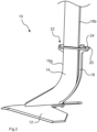
- the Fig. 2 shows the locked state, in which the clamping lever 18 is in a locking position and extends along a convexly curved rear end edge 16b of the tool carrier 14.
- the clamping lever 18 can be moved into the locking position manually and without the use of a tool.
- the tool changing system 10 has a holding member 20, which holds the clamping lever 18 in the locking position and prevents the clamped clamping lever 18 from snapping back.
- the holding member 20 is an annular body, which rests in a front region on a support 22 of the tool carrier 14.
- the support 22 is located on the front edge 16a of the tool carrier 14.
- the clamping lever 18 has a contour 24 in an upper end region.
- the contour 24 consists of an indentation formed by two spaced-apart material webs.
- the indentation of the contour 24 can be engaged with the holding member 20 to secure the clamping lever 18 in the locking position. If the holding member 20 is not fixed by the clamping lever 18, the Support 22 prevents the holding member 20 from falling down in an uncontrolled manner. In the locking position shown, the clamping lever 18 is elastically deformed.
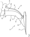
- the Fig. 3 shows the locking device 26 and the engagement mechanism 28 in detail.
- the engagement mechanism 28 is formed by the soil cultivation tool 12 and the tool carrier 14.
- the engagement mechanism 28 enables the soil cultivation tool 12 and the tool carrier 14 to be releasably engaged with one another in a non-destructive manner.
- the engagement mechanism 28 has two engagement bodies 32a, 32b, each engagement body 32a, 32b being configured to engage in a receiving recess 30a, 30b of the engagement mechanism 28.
- the engagement bodies 32a, 32b are located on the underside of the tool carrier 14 and are integral components of the tool carrier 14.
- the two receiving recesses 30a, 30b are located in the soil cultivation tool 12.
- the engagement bodies 32a, 32b After inserting the engagement bodies 32a, 32b into the receiving recesses 30a, 30b, the engagement bodies 32a, 32b protrude only slightly from the receiving recesses 30a, 30b, thus protecting the engagement bodies 32a, 32b from wear.
- the engagement bodies 32a, 32b each have a chamfered contact surface, which is pressed against the chamfered inner contours of the receiving recesses 30a, 30b by the clamping lever 18.
- the chamfers of the engagement bodies 32a, 32b and the inner contours of the receiving recesses 30a, 30b ensure that the soil tillage tool 12 and the tool carrier 14 wedge into each other when they are clamped together by means of the clamping lever 18.
- the chamfer angles ⁇ , ⁇ of the chamfers of the engagement bodies 32a, 32b and the inner contours of the receiving recesses 30a, 30b correspond and amount to 45 degrees in the illustrated embodiment.
- the clamping lever 18 is part of a locking device 26, by means of which the engagement mechanism can be locked.
- the clamping lever 18 has a locking portion 34, which can be inserted into the receiving recess 30b of the engagement mechanism 28.
- the receiving recess 30b can thus also be referred to as a lever receiving recess 30b.
- the Fig. 4 to 7 show the steps required to assemble a soil tillage tool 12.
- the soil tillage tool 12 must first be brought into engagement with the tool carrier 14.
- the soil tillage tool 12 is first brought in the vertical direction z into abutment with the lower edge of the tool carrier 14.
- the soil tillage tool 12 is positioned such that the engagement bodies 32a, 32b of the tool carrier 14 are inserted into the receiving recesses 30a, 30b of the soil tillage tool 12.
- the soil tillage tool 12 must then be moved rearward in the horizontal direction x so that the engagement bodies 32a, 32b engage with the receiving recesses 30a, 30b.
- the horizontal movement of the soil tillage tool 12 makes a free area of the receiving recess 30b accessible so that the locking section 34 of the clamping lever 18 can be inserted into the receiving recess 30b.
- the receiving recess 30b is accessible from the rear of the soil tillage tool 12 after the soil tillage tool 12 and tool carrier 14 have been brought into engagement, so that the clamping lever 18 can be inserted into the receiving recess 30b from the rear and above.
- the clamping lever 18 To complete the locking process, the clamping lever 18 must be moved into a locking position after being inserted into the lever receiving recess 30b.
- the Fig. 5 shows the clamping lever 18 during pivoting into the locking position, whereby the soil tillage tool 12 and the tool carrier 14 are clamped together by means of the clamping lever 18 during the pivoting of the clamping lever 18.
- the soil tillage tool 12 and the tool carrier 14 are clamped together, the soil tillage tool 12 is pushed backwards by the clamping lever 18.
- the soil tillage tool 12 and the tool carrier 14 can initially perform a relative movement to one another in an initial phase of the clamping. After the relative movement has ended, the clamping lever 18 A clamping force is built up, via which the soil cultivation tool 12 and the tool carrier 14 are fastened to one another.
- the clamping lever 18 has a tool contact area which, when the soil cultivation tool 12 and the tool carrier 14 are clamped together, is pressed against the contour of the lever receiving recess 30b.
- the tool contact area is located in the locking section 34 of the clamping lever 18. When the clamping lever 18 is moved into the locking position, the tool contact area of the clamping lever 18 is in contact with the contour of the lever receiving recess 30b.
- the clamping lever 18 has a carrier contact area which, when the soil cultivation tool 12 and the tool carrier 14 are clamped together, is pressed against a lever guide area of the tool carrier.
- the carrier contact area of the clamping lever 18 is in contact with the lever guide area of the tool carrier 14.
- the carrier contact area of the clamping lever 18 has a convexly curved contact surface 36.
- the lever guide area of the tool carrier 14 has a concavely curved contact surface 38.
- the convexly curved contact surface 36 on the clamping lever 18 and the concavely curved contact surface 38 on the tool carrier 14 together form a sliding bearing or pivot bearing 40.
- the pivot bearing 40 allows a guided rotary movement of the clamping lever 18 in the pivoting direction ⁇ .
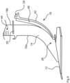
- the Fig. 6 shows that the clamping lever 18 is elastically deformed, namely elastically bent, in a deformation region 42 when the soil cultivation tool 12 and the tool carrier 14 are clamped together.
- the clamping lever 18 can therefore also be referred to as a spring bar.
- the clamping lever 18 can be moved into the locking position and secured to the holding member 20 manually using one or more fingers F. After the contouring 24 has been inserted into the annular holding member 20, the clamping lever 18 extends along the rear curved edge 16b of the tool carrier 14.
- the curved edge profile of the tool carrier 14 belongs to a rear end edge 16b of the tool carrier 14.
- elastically deformable material 46 for example, foam rubber
- the remaining gap between the rear edge 16b of the tool carrier 14 and the clamping lever 18 can be closed, so that no dirt can accumulate in this area.
- markings 44 are provided on the tool carrier 14 for adjusting the position of the soil cultivation tool 12 and for adjusting the working depth. The markings 44 form a scale for adjusting the height of the soil cultivation tool 12.
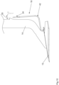
- the Fig. 9 shows the clamping lever 18, which in this embodiment is designed as a bent wire part, during pivoting into the locking position, wherein the soil tillage tool 12 and the tool carrier 14 are clamped together by means of the clamping lever 18 during the pivoting of the clamping lever 18.
- the soil tillage tool 12 and the tool carrier 14 are clamped together, the soil tillage tool 12 is pushed backward by the clamping lever 18.
- the soil tillage tool 12 and the tool carrier 14 can initially perform a relative movement to one another in an initial phase of the clamping. After the relative movement has ended, a clamping force is built up via the clamping lever 18, via which the soil tillage tool 12 and the tool carrier 14 are fastened to one another.
- the clamping lever 18 has a tool contact area which is pressed against the contour of the lever receiving recess 30b when the soil tillage tool 12 and the tool carrier 14 are clamped together.
- the tool contact area is located in the locking section 34 of the clamping lever 18.
- the clamping lever 18 has a carrier contact area, which is pressed against a lever guide area of the tool carrier 14 when the soil cultivation tool 12 and the tool carrier 14 are clamped together.
- the carrier contact area of the clamping lever 18 is in contact with the lever guide area of the tool carrier 14.
- the carrier contact area of the clamping lever 18 has a convexly curved contact surface 36.
- the lever guide area of the tool carrier 14 has a concavely curved contact surface 38.
- the convexly curved contact surface 36 on the clamping lever 18 and the concavely curved contact surface 38 on the tool carrier 14 together form a sliding bearing or pivot bearing 40.
- the pivot bearing 40 allows a guided rotary movement of the clamping lever 18 in the pivoting direction ⁇ .
- the clamping lever 18, designed as a bent wire part, can also be referred to as a spring clip.
- the clamping lever 18 is essentially U-shaped, with the two open ends forming the locking section 34 of the clamping lever 18. At the closed end of the clamping lever 18, a loop is thus formed, which can serve as a contour 24.
- the contour 24 can engage behind the holding member 20 designed as a hook on the tool carrier 14.
- the clamping lever 18 is held in its locked position by the hook-shaped holding member 20 as soon as the loop-shaped contour 24 engages behind it.
- the clamping lever 18 has a mirror-symmetrical contour, which gives it its open shape.
- the Fig. 10 shows that the clamping lever 18 is elastically deformed, namely elastically bent, in a deformation region 42 when the soil cultivation tool 12 and the tool carrier 14 are clamped together.
- the clamping lever 18 can therefore also be referred to as a spring clip. Moving the clamping lever 18 into the locking position and securing the clamping lever 18 to the holding member 20 can be done manually.
- a Fig. 11 The assembly tool shown can be used.
- the assembly tool can be applied from the side on the front of the tool carrier 14 and on the underside of the clamping lever 18. It has a lateral opening for this purpose.
- the clamping lever 18 can then be moved by levering the assembly tool upwards into its locking position, in which the contour 24 engages behind the holding member 20.
- the Assembly tools can also be used to release the locking position.
Landscapes
- Life Sciences & Earth Sciences (AREA)
- Engineering & Computer Science (AREA)
- Mechanical Engineering (AREA)
- Soil Sciences (AREA)
- Environmental Sciences (AREA)
- Soil Working Implements (AREA)
- Cultivation Receptacles Or Flower-Pots, Or Pots For Seedlings (AREA)
Priority Applications (1)
| Application Number | Priority Date | Filing Date | Title |
|---|---|---|---|
| RS20250625A RS66935B1 (sr) | 2021-03-04 | 2021-08-24 | Sistem za zamenu alata za mašine za obradu tla |
Applications Claiming Priority (2)
| Application Number | Priority Date | Filing Date | Title |
|---|---|---|---|
| DE102021105179.7A DE102021105179A1 (de) | 2021-03-04 | 2021-03-04 | Werkzeugwechselsystem für Bodenbearbeitungsmaschinen |
| PCT/EP2021/073321 WO2022184284A1 (de) | 2021-03-04 | 2021-08-24 | Werkzeugwechselsystem fuer bodenbearbeitungsmaschinen |
Publications (3)
| Publication Number | Publication Date |
|---|---|
| EP4301123A1 EP4301123A1 (de) | 2024-01-10 |
| EP4301123C0 EP4301123C0 (de) | 2025-06-04 |
| EP4301123B1 true EP4301123B1 (de) | 2025-06-04 |
Family
ID=77499845
Family Applications (1)
| Application Number | Title | Priority Date | Filing Date |
|---|---|---|---|
| EP21759324.3A Active EP4301123B1 (de) | 2021-03-04 | 2021-08-24 | Werkzeugwechselsystem fuer bodenbearbeitungsmaschinen |
Country Status (9)
| Country | Link |
|---|---|
| US (1) | US20240147882A1 (pl) |
| EP (1) | EP4301123B1 (pl) |
| CA (1) | CA3211681A1 (pl) |
| DE (1) | DE102021105179A1 (pl) |
| ES (1) | ES3036332T3 (pl) |
| HU (1) | HUE072237T2 (pl) |
| PL (1) | PL4301123T3 (pl) |
| RS (1) | RS66935B1 (pl) |
| WO (1) | WO2022184284A1 (pl) |
Families Citing this family (1)
| Publication number | Priority date | Publication date | Assignee | Title |
|---|---|---|---|---|
| DK4430936T3 (da) | 2023-03-16 | 2025-05-19 | Amazonen Werke H Dreyer Se & Co Kg | Redskabsudskiftningssystem til en landbrugsjordbearbejdningsmaskine og fremgangsmåde til fastgørelse af et jordbearbejdningsredskab |
Family Cites Families (8)
| Publication number | Priority date | Publication date | Assignee | Title |
|---|---|---|---|---|
| DE2365914C3 (de) * | 1973-10-18 | 1978-04-20 | Fritz 7315 Weilheim Guettler | Vorrichtung zum Befestigen von landwirtschaftlichen Bodenbearbeitungswerkzeugen |
| US4799555A (en) | 1987-01-28 | 1989-01-24 | Badger Carl L | Chisel plow mounting assembly |
| DE4415974A1 (de) | 1994-05-06 | 1995-11-09 | Dickhaus & Partner Gmbh | Vorrichtung zum Ausführen von Handarbeiten |
| US6289996B1 (en) * | 2001-03-20 | 2001-09-18 | Alan F. Parish | Securing device for knock-on earthworking tool |
| US20040256121A1 (en) * | 2003-06-09 | 2004-12-23 | Pollard Lorne R. | Cultivator sweep assembly |
| AT501965B1 (de) * | 2005-05-17 | 2007-04-15 | Vogel & Noot Landmaschinen Gmb | Grubberzinken sowie scharspitze hierfür |
| DE102013102420A1 (de) * | 2013-03-11 | 2014-09-11 | Betek Gmbh & Co. Kg | Scharspitze bzw. Werkzeugkombination mit einer Scharspitze |
| DE102016106148A1 (de) | 2016-04-05 | 2017-10-05 | Betek Gmbh & Co. Kg | Bearbeitungswerkzeug |
-
2021
- 2021-03-04 DE DE102021105179.7A patent/DE102021105179A1/de active Pending
- 2021-08-24 US US18/279,987 patent/US20240147882A1/en active Pending
- 2021-08-24 PL PL21759324.3T patent/PL4301123T3/pl unknown
- 2021-08-24 RS RS20250625A patent/RS66935B1/sr unknown
- 2021-08-24 EP EP21759324.3A patent/EP4301123B1/de active Active
- 2021-08-24 CA CA3211681A patent/CA3211681A1/en active Pending
- 2021-08-24 ES ES21759324T patent/ES3036332T3/es active Active
- 2021-08-24 HU HUE21759324A patent/HUE072237T2/hu unknown
- 2021-08-24 WO PCT/EP2021/073321 patent/WO2022184284A1/de not_active Ceased
Also Published As
| Publication number | Publication date |
|---|---|
| EP4301123C0 (de) | 2025-06-04 |
| WO2022184284A1 (de) | 2022-09-09 |
| EP4301123A1 (de) | 2024-01-10 |
| CA3211681A1 (en) | 2022-09-09 |
| RS66935B1 (sr) | 2025-07-31 |
| PL4301123T3 (pl) | 2025-07-28 |
| HUE072237T2 (hu) | 2025-11-28 |
| DE102021105179A1 (de) | 2022-09-08 |
| US20240147882A1 (en) | 2024-05-09 |
| ES3036332T3 (en) | 2025-09-17 |
Similar Documents
| Publication | Publication Date | Title |
|---|---|---|
| DE69636251T2 (de) | Verschleisselement für eine schneidkarte eines baggers | |
| EP1407649B1 (de) | Aufsteckanordnung für ein Bodenbearbeitungswerkzeug | |
| DE69000650T2 (de) | Vorrichtung zum brechen von elementen aus beton oder aehnlichem material. | |
| DE69514905T2 (de) | Backen eines abbrucharbeitsgerätes mit austauschbaren arbeitsflächen | |
| DE60118708T3 (de) | Arbeitswerkzeug mit auswechselbarer Spitze | |
| DE2500217B2 (de) | Vorrichtung zum Anschließen auswechselbarer unterschiedlicher Arbeitswerkzeuge eines Baggers o.dgl | |
| EP1474961B1 (de) | Halteeinrichtung | |
| DE202014010340U1 (de) | Scharspitze bzw. Werkzeugkombination mit einer Scharspitze | |
| EP1522635B1 (de) | Schnellwechselkupplung zur Befestigung der Arbeitswerkzeuge an einem Baggerausleger | |
| DE102012107476A1 (de) | Bearbeitungswerkzeug für den Feldbau | |
| WO2022184284A1 (de) | Werkzeugwechselsystem fuer bodenbearbeitungsmaschinen | |
| DE102016204483B4 (de) | Befestigungselement mit mindestens einem Clip zur Herstellung einer Verbindung mit einem korrespondierenden Ansteckelement und Anordnung eines Befestigungselements an einem Ansteckelement | |
| EP1653088B1 (de) | Zylinderanordnung mit einstellbarem Anschlag | |
| EP2591650B1 (de) | Grubberzinken mit mittels einer Formschluss-Schnellbefestigung befestigbarer Scharspitze | |
| CH703286A2 (de) | Kupplungsteil und Anbaugerät mit Kupplungsteil | |
| DE102016110396B4 (de) | Bodenbearbeitungsgerät | |
| DE102010017179A1 (de) | Kupplungsteil und Anbaugerät mit Kupplungsteil | |
| DE3788801T2 (de) | Werkzeug zum Bearbeiten eines Mediums, wie z.B. Erdreich. | |
| EP3235358A1 (de) | Scharspitze zur verwendung in einem scharsystem zur bodenbearbeitung | |
| DE10019003A1 (de) | Leicht lösbarer Spindel-Muffen-Verschluss für eine Einbaugarnitur | |
| EP4486104B1 (de) | Werkzeugwechselsystem für eine landwirtschaftliche bodenbearbeitungsmaschine und verfahren zum befestigen eines bodenbearbeitungswerkzeuges | |
| EP4101274B1 (de) | Landwirtschaftliche arbeitsmaschine | |
| DE102018208024A1 (de) | Scharsystem und Scharspitze zur Verwendung in einem Scharsystem zur Bodenbearbeitung | |
| DE102014112606B4 (de) | Verbindung eines Werkzeughalmes mit einer Halmtasche | |
| EP3045027A1 (de) | Bodenbearbeitungsschar |
Legal Events
| Date | Code | Title | Description |
|---|---|---|---|
| STAA | Information on the status of an ep patent application or granted ep patent |
Free format text: STATUS: UNKNOWN |
|
| STAA | Information on the status of an ep patent application or granted ep patent |
Free format text: STATUS: THE INTERNATIONAL PUBLICATION HAS BEEN MADE |
|
| PUAI | Public reference made under article 153(3) epc to a published international application that has entered the european phase |
Free format text: ORIGINAL CODE: 0009012 |
|
| STAA | Information on the status of an ep patent application or granted ep patent |
Free format text: STATUS: REQUEST FOR EXAMINATION WAS MADE |
|
| 17P | Request for examination filed |
Effective date: 20230713 |
|
| AK | Designated contracting states |
Kind code of ref document: A1 Designated state(s): AL AT BE BG CH CY CZ DE DK EE ES FI FR GB GR HR HU IE IS IT LI LT LU LV MC MK MT NL NO PL PT RO RS SE SI SK SM TR |
|
| DAV | Request for validation of the european patent (deleted) | ||
| DAX | Request for extension of the european patent (deleted) | ||
| GRAP | Despatch of communication of intention to grant a patent |
Free format text: ORIGINAL CODE: EPIDOSNIGR1 |
|
| STAA | Information on the status of an ep patent application or granted ep patent |
Free format text: STATUS: GRANT OF PATENT IS INTENDED |
|
| INTG | Intention to grant announced |
Effective date: 20250213 |
|
| GRAS | Grant fee paid |
Free format text: ORIGINAL CODE: EPIDOSNIGR3 |
|
| GRAA | (expected) grant |
Free format text: ORIGINAL CODE: 0009210 |
|
| STAA | Information on the status of an ep patent application or granted ep patent |
Free format text: STATUS: THE PATENT HAS BEEN GRANTED |
|
| AK | Designated contracting states |
Kind code of ref document: B1 Designated state(s): AL AT BE BG CH CY CZ DE DK EE ES FI FR GB GR HR HU IE IS IT LI LT LU LV MC MK MT NL NO PL PT RO RS SE SI SK SM TR |
|
| REG | Reference to a national code |
Ref country code: GB Ref legal event code: FG4D Free format text: NOT ENGLISH |
|
| REG | Reference to a national code |
Ref country code: CH Ref legal event code: EP |
|
| REG | Reference to a national code |
Ref country code: DE Ref legal event code: R096 Ref document number: 502021007670 Country of ref document: DE |
|
| REG | Reference to a national code |
Ref country code: IE Ref legal event code: FG4D Free format text: LANGUAGE OF EP DOCUMENT: GERMAN |
|
| U01 | Request for unitary effect filed |
Effective date: 20250619 |
|
| U07 | Unitary effect registered |
Designated state(s): AT BE BG DE DK EE FI FR IT LT LU LV MT NL PT RO SE SI Effective date: 20250630 |
|
| REG | Reference to a national code |
Ref country code: SK Ref legal event code: T3 Ref document number: E 46638 Country of ref document: SK |
|
| U20 | Renewal fee for the european patent with unitary effect paid |
Year of fee payment: 5 Effective date: 20250709 |
|
| REG | Reference to a national code |
Ref country code: GR Ref legal event code: EP Ref document number: 20250401243 Country of ref document: GR Effective date: 20250707 |
|
| REG | Reference to a national code |
Ref country code: ES Ref legal event code: FG2A Ref document number: 3036332 Country of ref document: ES Kind code of ref document: T3 Effective date: 20250917 |
|
| PGFP | Annual fee paid to national office [announced via postgrant information from national office to epo] |
Ref country code: HU Payment date: 20250728 Year of fee payment: 5 |
|
| PGFP | Annual fee paid to national office [announced via postgrant information from national office to epo] |
Ref country code: ES Payment date: 20250905 Year of fee payment: 5 |
|
| PG25 | Lapsed in a contracting state [announced via postgrant information from national office to epo] |
Ref country code: NO Free format text: LAPSE BECAUSE OF FAILURE TO SUBMIT A TRANSLATION OF THE DESCRIPTION OR TO PAY THE FEE WITHIN THE PRESCRIBED TIME-LIMIT Effective date: 20250904 |
|
| PGFP | Annual fee paid to national office [announced via postgrant information from national office to epo] |
Ref country code: GR Payment date: 20250716 Year of fee payment: 5 |
|
| PGFP | Annual fee paid to national office [announced via postgrant information from national office to epo] |
Ref country code: GB Payment date: 20250703 Year of fee payment: 5 |
|
| PG25 | Lapsed in a contracting state [announced via postgrant information from national office to epo] |
Ref country code: HR Free format text: LAPSE BECAUSE OF FAILURE TO SUBMIT A TRANSLATION OF THE DESCRIPTION OR TO PAY THE FEE WITHIN THE PRESCRIBED TIME-LIMIT Effective date: 20250604 |
|
| PGFP | Annual fee paid to national office [announced via postgrant information from national office to epo] |
Ref country code: CH Payment date: 20250901 Year of fee payment: 5 |
|
| PGFP | Annual fee paid to national office [announced via postgrant information from national office to epo] |
Ref country code: RS Payment date: 20250811 Year of fee payment: 5 Ref country code: CZ Payment date: 20250730 Year of fee payment: 5 |
|
| PGFP | Annual fee paid to national office [announced via postgrant information from national office to epo] |
Ref country code: SK Payment date: 20250714 Year of fee payment: 5 |
|
| REG | Reference to a national code |
Ref country code: HU Ref legal event code: AG4A Ref document number: E072237 Country of ref document: HU |
|
| PG25 | Lapsed in a contracting state [announced via postgrant information from national office to epo] |
Ref country code: IS Free format text: LAPSE BECAUSE OF FAILURE TO SUBMIT A TRANSLATION OF THE DESCRIPTION OR TO PAY THE FEE WITHIN THE PRESCRIBED TIME-LIMIT Effective date: 20251004 |
|
| PG25 | Lapsed in a contracting state [announced via postgrant information from national office to epo] |
Ref country code: SM Free format text: LAPSE BECAUSE OF FAILURE TO SUBMIT A TRANSLATION OF THE DESCRIPTION OR TO PAY THE FEE WITHIN THE PRESCRIBED TIME-LIMIT Effective date: 20250604 |
|
| PGFP | Annual fee paid to national office [announced via postgrant information from national office to epo] |
Ref country code: PL Payment date: 20250627 Year of fee payment: 5 |
|
| PG25 | Lapsed in a contracting state [announced via postgrant information from national office to epo] |
Ref country code: MC Free format text: LAPSE BECAUSE OF FAILURE TO SUBMIT A TRANSLATION OF THE DESCRIPTION OR TO PAY THE FEE WITHIN THE PRESCRIBED TIME-LIMIT Effective date: 20250604 |
|
| PLBE | No opposition filed within time limit |
Free format text: ORIGINAL CODE: 0009261 |
|
| STAA | Information on the status of an ep patent application or granted ep patent |
Free format text: STATUS: NO OPPOSITION FILED WITHIN TIME LIMIT |
|
| REG | Reference to a national code |
Ref country code: CH Ref legal event code: L10 Free format text: ST27 STATUS EVENT CODE: U-0-0-L10-L00 (AS PROVIDED BY THE NATIONAL OFFICE) Effective date: 20260416 |
|
| 26N | No opposition filed |
Effective date: 20260305 |