EP4301488B1 - Dispositif de filtrage - Google Patents
Dispositif de filtrage Download PDFInfo
- Publication number
- EP4301488B1 EP4301488B1 EP22702891.7A EP22702891A EP4301488B1 EP 4301488 B1 EP4301488 B1 EP 4301488B1 EP 22702891 A EP22702891 A EP 22702891A EP 4301488 B1 EP4301488 B1 EP 4301488B1
- Authority
- EP
- European Patent Office
- Prior art keywords
- filter
- head
- filter element
- filter device
- cavity
- Prior art date
- Legal status (The legal status is an assumption and is not a legal conclusion. Google has not performed a legal analysis and makes no representation as to the accuracy of the status listed.)
- Active
Links
Images


Classifications
-
- B—PERFORMING OPERATIONS; TRANSPORTING
- B01—PHYSICAL OR CHEMICAL PROCESSES OR APPARATUS IN GENERAL
- B01D—SEPARATION
- B01D29/00—Filters with filtering elements stationary during filtration, e.g. pressure or suction filters, not covered by groups B01D24/00 - B01D27/00; Filtering elements therefor
- B01D29/11—Filters with filtering elements stationary during filtration, e.g. pressure or suction filters, not covered by groups B01D24/00 - B01D27/00; Filtering elements therefor with bag, cage, hose, tube, sleeve or like filtering elements
- B01D29/13—Supported filter elements
- B01D29/23—Supported filter elements arranged for outward flow filtration
- B01D29/232—Supported filter elements arranged for outward flow filtration with corrugated, folded or wound sheets
-
- B—PERFORMING OPERATIONS; TRANSPORTING
- B01—PHYSICAL OR CHEMICAL PROCESSES OR APPARATUS IN GENERAL
- B01D—SEPARATION
- B01D29/00—Filters with filtering elements stationary during filtration, e.g. pressure or suction filters, not covered by groups B01D24/00 - B01D27/00; Filtering elements therefor
- B01D29/50—Filters with filtering elements stationary during filtration, e.g. pressure or suction filters, not covered by groups B01D24/00 - B01D27/00; Filtering elements therefor with multiple filtering elements, characterised by their mutual disposition
- B01D29/56—Filters with filtering elements stationary during filtration, e.g. pressure or suction filters, not covered by groups B01D24/00 - B01D27/00; Filtering elements therefor with multiple filtering elements, characterised by their mutual disposition in series connection
- B01D29/58—Filters with filtering elements stationary during filtration, e.g. pressure or suction filters, not covered by groups B01D24/00 - B01D27/00; Filtering elements therefor with multiple filtering elements, characterised by their mutual disposition in series connection arranged concentrically or coaxially
-
- B—PERFORMING OPERATIONS; TRANSPORTING
- B01—PHYSICAL OR CHEMICAL PROCESSES OR APPARATUS IN GENERAL
- B01D—SEPARATION
- B01D36/00—Filter circuits or combinations of filters with other separating devices
- B01D36/001—Filters in combination with devices for the removal of gas, air purge systems
-
- B—PERFORMING OPERATIONS; TRANSPORTING
- B01—PHYSICAL OR CHEMICAL PROCESSES OR APPARATUS IN GENERAL
- B01D—SEPARATION
- B01D2201/00—Details relating to filtering apparatus
- B01D2201/29—Filter cartridge constructions
- B01D2201/291—End caps
- B01D2201/298—End caps common to at least two filtering elements
Definitions
- the invention relates to a filter device with the features in the preamble of claim 1.
- Filter devices of this type as part of hydraulic systems are state of the art. To avoid impairments of safety-relevant components such as valves, hydraulic drives, control elements and the like, it is essential that the respective filter device guarantees a consistent quality of the filtered media. The flawless function of the filter device in the system is therefore a basic requirement for operational safety.
- the known filter device uses, among other things, a jet pump as a degassing device, which is operated by means of a media flow, which is generated in particular by a hydraulic pump, such as a gear pump.
- the jet pump can be operated by an external media flow or, advantageously, by a medium produced from the filtrate of the filter device.
- the known solution is extremely effective in terms of the amount of gas discharged; however, this requires a certain amount of equipment and, in particular, additional energy is required to operate the jet pump via the hydraulic pump for the degassing process.
- the US 2020/0038785 A1 describes a filter device with the features in the preamble of claim 1, consisting of at least two filter elements arranged coaxially to one another, which delimit a cavity between them, wherein the inner side of the outer filter element facing the cavity at least partially has a separating device for gas bubbles, such as air bubbles, wherein the cavity opens into at least one discharge opening for such gas bubbles on the head side, wherein the two filter elements are placed one inside the other and received in an end cap on the foot and head side, wherein the respective discharge opening is formed from a passage, such as a bore, in the head-side end cap, which connects the cavity between the filter elements with the environment, and wherein the head-side end cap with its respective discharge opening is overlapped by a cover cap at a predeterminable distance.
- the invention is based on the object of creating a filter device that enables effective degassing of a fluid, such as hydraulic oil, with little equipment outlay, without having to provide additional drive energy for the degassing device.
- a filter device with the features of patent claim 1 in its entirety.
- an annular gap is formed in the region of the overlap between the cover cap and the head-side end cap, via which the respective fluid originating from a discharge opening is guided to an outer peripheral side of the outer hollow cylindrical filter element.
- the fluid flowing upwards through the passages, particularly in the form of the holes, is homogeneously guided outwards by the plate geometry of the cover cap that overlaps the head-side end cap, in the direction of the outer support tube of the outer filter element, from where it runs down as a thin, highly air-containing film in the direction of the respective tank fluid level.
- the thin film causes the air bubble to be close to the surface of the environment inside the tank, which promotes its separation.
- the inner side of the outer filter element facing the cavity at least partially forms a separating device for gas bubbles, such as air bubbles, and because the cavity opens into at least one discharge opening for such gas bubbles at the head end, effective degassing of the fluid to be cleaned of particle contamination occurs without additional drive energy for an additional device, such as a jet pump.
- the innermost filter element essentially serves the aforementioned particle filtration
- the outermost filter element which is preferably arranged coaxially, allows a type of air bubble coalescence on the inner side, which faces adjacent to the aforementioned cavity between the two filter elements.
- the filter device experiences a supply of unfiltered material on the inner side of the innermost filter element, which is flowed through from the inside to the outside, just like the outermost filter element.
- the gas or air bubbles are not present in their pure form, but are embedded and thus part of a fluid or foam that contains more or less gas or air and only after passing through the respective discharge opening, the fluid is degassed, with the fluid components being discharged in the opposite direction to the fluid side of the device.
- the separation device mentioned which forms a kind of barrier layer for gas bubbles on the inside of the outer filter element, results in a kind of gradual classification or graduation according to the size of the individual air bubbles and coalescence of the smaller air bubbles into correspondingly large ones until they have reached a size that can rise and can thus be effectively separated on a fluid surface, for example in a storage tank.
- the respective discharge opening for these gas bubbles which is smaller in diameter than the diameter of the annular cavity between the elements on the head side of the filter device, promotes parallel flow through the filter element assembly, and it has been shown that the parallel connection in this way reduces the flow velocity in the outer filter element, which brings about an improved coalescence effect and thus air separation.
- the filter device according to the invention is preferably intended for so-called in-tank solutions, in which the entire filter device is fully integrated between different fluid levels in a tank.
- the two filter elements are placed inside each other and housed in an end cap on the foot and head sides, and the respective discharge opening is formed from a passage, such as a hole, in the head-side end cap, which connects the cavity between the filter elements with the environment.
- a passage such as a hole
- the passages mentioned are designed as a hole, there is an improved discharge of air bubbles, which is also possible in the form of a fluid-foam mixture with a high air content.
- the fluid to be degassed flows through the filter device from the foot side to the head side.
- the head-side parts of the filter device are above the tank fluid level, so that the part of the filter device above the fluid level allows a calm outflow, particularly of air, from the hydraulic medium close to the surface.
- a calm outflow particularly of air
- the passages mentioned in the head-side end cap of the filter device allow a channeled release of the separated gas, particularly in the form of air bubbles, parallel to the orientation of the element material of the outer filter element.
- it is actually a fluid or foam with a high air content that flows out of the openings, whereby the air can then degas on the flow path to the fluid surface.
- the outer peripheral side of the outer filter element is formed from a perforated support tube, and the perforation, in particular in the form of a hole in the support tube, leads to a braking effect when running down, which increases the residence time and in turn promotes the release of the air bubbles into the ambient air above the fluid level of the tank.
- a flow guide element is arranged on the inside of the inner hollow-cylindrical filter element in the area of the head-side end cap.
- the flow guide element is preferably designed in the form of an inwardly tapering cone, the tip of which opens into the interior of the cavity of the inner filter element and which serves to prevent an unwanted accumulation of air bubbles under the end cap in the inner area of the inner filter element.
- the head-side end cap i.e. in the area of the flow guide element, is preferably connected to the cover cap, preferably by means of an adhesive or screw connection; however, it is also possible to form the cover cap and associated end cap from one component, for example by means of an injection molding process.
- the two filter elements with their end caps and the cover cap form an exchangeable unit for preferred use in a fluid tank. Since the outer filter element in particular becomes clogged with particle contamination during use of the filter device, it is advisable to replace the used unit with a new element, which also applies to the outer filter element, which is at least partially used up by particle contamination, despite the internal filter element. It is preferably provided that the filter fineness of the innermost filter element is finer than that of the outermost filter element.
- the inner filter element also has a perforated support tube in the direction of the cavity.
- a suitable media layer with coalescence properties can be used, for example consisting of a fleece with a predetermined pore size gradient, which, starting from an innermost fine structure, is visibly converted into a coarse structure towards the outflow side, which, when fluid flows through the outer filter element, leads to the bubbles regularly dispersed in the fluid being finely dispersed due to the coalescence properties the media layer, which is designed as a release layer, is combined to form volumetrically larger units.
- the fiber material preferably used here usually in the form of a fleece, can contain polyester fibers, which facilitates the degassing processes from the fluid.
- any other type of media layer that is suitable for the formation of large air bubbles can be used as a barrier layer; in particular, a voluminous fibrous 3D matrix can serve as a degassing barrier layer.
- the release layer on the inside of the outer filter element from a grid, net or fabric structure, whereby the release layer in question can also be formed from several media layers of the same or different types.
- the release layer in question can also be formed from several media layers of the same or different types.
- several grid or net structures with different opening widths can be placed on top of one another as individual layers for degassing or the combination of such net or grid structures with suitable fleeces or with a 3D matrix can be used, as explained above.
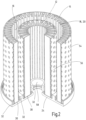
- the Figure 1 shows a longitudinal section through the filter device as a whole. This has two along a common longitudinal axis 10 (see Fig. 3 ) filter elements 12, 14 arranged coaxially to one another, which delimit a circumferential annular cavity 16 between them on the outer and inner circumferences.
- the inner side 18 of the outer filter element 14 facing the cavity 16 has a separation device 20 for gas bubbles, such as air bubbles, the cavity 16 opening into individual discharge openings 22 for such gas bubbles on the head side as shown in the figures.
- the two filter elements 12, 14 are placed one inside the other and each received on the foot and head side in a common end cap 24, 26, the respective discharge opening 22 being formed from a passage, in particular in the form of a bore, in the head-side end cap 26, which connects the cavity 16 between the filter elements 12, 14 with the environment 28.
- the respective end caps 24 and 26 are formed in one piece and have ring-shaped receptacles 30 in which the free end faces of the respective filter elements 12, 14 are received; in particular, the said receptacles 30 form a type of adhesive bed via which the respective filter elements 12, 14 are firmly connected to the end caps 24, 26 at the end face.
- the respective adhesive bed is omitted from the figures, with the respective adhesive bed extending between limiting webs 32 of the individual receptacles 30.
- the head-side end cap 26 with its respective discharge opening 22 is overlapped by a plate-like cover cap 34.
- the cover cap 34 forms a closed circular surface on its upper side and is towards the Fig. 1 seen, provided with a peripheral edge 36 projecting downwards, which maintains a radial distance from the outermost peripheral limiting web 32.
- the free front end 38 of the peripheral edge 36 opens out above the lower end 40 of the outermost limiting web 32, the free annular edge 40 formed in this way of this web 32 running parallel to the free end annular edge 38 of the peripheral edge 36.
- the cover cap 34 Arranged coaxially to the longitudinal axis 10, the cover cap 34 has a projection 42 along its lower surface, which engages with a pin-like extension 44 in a blind hole 46 of a flow guide element 48.
- the plate-like projection 42 overlaps the blind hole 46 on the edge and lies flush on the top of the flow guide element 48 as part of the head-side end cap 26.
- the axial height of the projection 42 determines the predetermined distance between the head-side end cap 26 and the cover cap 34 and in this respect specifies the distance for an annular gap 50, which is formed in the area of the overlap between the cover cap 34 and the head-side end cap 26.
- This annular gap 50 continues on the outer circumference with the same distance between the outermost upper limiting web 32 and the downwardly projecting peripheral edge 36 of the cover cap 34.
- the fluid originating from the respective discharge opening 22 is guided via the annular gap 50 to the outer circumference side 52 of the outer hollow cylindrical filter element 14.
- the outer circumference side 52 of the outer filter element 14 is formed from a perforated support tube 54, which is provided with symmetrically distributed holes for this purpose as shown.
- a further comparable formed support tube 56 forms the outer peripheral side for the inner filter element 12.
- Fig. 1 further shows, there are several discharge openings 22, for example two to twelve, diametrically opposite one another to the longitudinal axis 10, which completely penetrate the central limiting web 32 on the head-side end cap 26 and thus establish a fluid connection between the circumferentially formed annular gap 50 and the annular cavity 16.
- the discharge openings 22 extend uniformly with a defined radial distance along a fictitious circle coaxially to the longitudinal axis 10.
- the cover cap 34 can also be an integral part of the head-side end cap 26.
- the discharge openings 22, each formed as bores in the central limiting web 32 form channel-like extensions on the top of the cavity 16 and are all provided with the same bore length and the same bore diameter.
- the innermost annular limiting web 32 on the foot-side end cap 24 forms a receiving ring 58 in which a circumferential groove for a sealing ring 60 (see Fig. 3 ) is inserted.
- the corresponding receiving ring 58 serves, as the Fig. 3 shows the setting of a filter device according to the Figures 1 and 2 on an inlet nozzle 62, which is connected at the bottom to a tank housing 64 of a fluid tank of conventional design, so that this will not be discussed in more detail here, and in particular the tank is in Fig. 3 in a very simplified way with only 4 boundary walls 66.
- the Fig. 1 shows, the flow guide element 48 is guided on the hollow cylindrical inner side of the inner filter element 12 at the head side and opens conically in the direction of the longitudinal axis 10 into the interior of the hollow cylindrical filter element 12.
- the two filter elements 12, 14 are pleated.
- the pleated filter mat structure formed in this way can have a multi-layer structure depending on the functionality of the filter, which is known in the art.
- the respective pleats are supported on the outer circumference for the outer filter element 14 on the outer support tube 54 and for the inner filter element 12 on the further support tube 56.
- the innermost filter element 12 is mainly used for particle filtration, i.e. the removal of particulate contamination from the fluid flow, whereas the outer filter element 14 is mainly used for degassing the fluid.
- the respective pleat height selected is in the range of 5 to 35 mm and 3- to 7-layer filter mats are preferably used for the two filter elements 12, 14.
- a pleat density of between 1 and 10 pleats/cm is preferably selected for the respective element 12, 14.
- the separating device 20 is arranged on the inner side 18 of the outer filter element 14 and is preferably folded into the other folds of the outer filter element 14; however, it is also possible to arrange the separating device, for example as a hollow cylindrical body (not shown), along the inner peripheral side 18 of the outer filter element 14 as a separate component.
- the hollow cylindrical body in question can be formed by a coalescing support structure, for example in the form of a support tube with surrounding PET film.
- each layer can have a mesh size of between 10 and 1200 ⁇ m .
- the layer used in each case can be made of stainless steel or plastic material.
- No further support tube is provided on the respective inner peripheral side of the filter elements 12, 14, and since the respective element 12, 14 is flowed through from the inside to the outside, a support of the respective element material is sufficient on the outer support tubes 54, 56.
- the following weaves can be used for the respective wire mesh: a twill weave, a satin weave or, in the simplest case, a plain weave.
- the following weave types are possible: 1-1 weave, 2-2 weave, 4-1 weave, 5-1 weave, 2-1 weave. It has been found to be particularly preferred to use a plain weave (1-1 weave) for the two outer layers and a so-called 3-twill weave or 2-1 weave for the middle layer.
- the representation according to the Fig. 3 shows a typical installation situation in a tank housing 64 of a fluid storage tank, wherein according to the illustration according to the Fig. 3 the filter device as a whole is placed on the inlet nozzle 62 of the tank via its lower receiving ring 58, in a sealed manner by means of the sealing ring 60 in the corresponding receiving groove of the ring 58. Furthermore, for the sake of better understanding and as an example in the Fig. 3 a medium filling level 68 and a minimum filling level 70 are indicated.
- a venting option (not shown) can be provided for the removal of air from the tank interior, preferably on the upper tank wall 66, as well as a drainage option on the underside of the tank for fluid that has been cleaned of particulate contamination and degassed, whereby the drainage option in this regard is also not shown for the sake of simplicity.
- the fluid to be treated flows during operation of the filter device via the inlet nozzle 62 into the interior of the innermost filter element 12, whereby a cleaning of particulate contamination takes place in that the fluid passes from the inside to the outside and the filter element 12 into the cavity 16 between the elements 12, 14.
- the thus cleaned Fluid can then also pass through the outer filter element 14 with further cleaning if necessary and thus reach the interior of the tank housing 64.
- the grid-like or net-like separating device 20 on the inside of the outer filter element 14 is also flowed through, whereby the separating device 20 forms a kind of barrier layer for gas, such as air, with the result that initially finely distributed gas bubbles in the fluid coalesce in dispersed form to form larger bubbles and accordingly in the direction of the Fig. 3 seen, rise upwards and always above the fluid level 68, 70 present in the tank.
- the gas bubbles or air bubbles rising upwards in this way then exit via the respective upper discharge opening 22 onto the air side (environment 28) inside the tank housing 64.
- the filter device basically also manages without a cover cap 34, the presence of which brings corresponding advantages, in particular since the separated air can still be wetted with liquid, which is advantageously discharged to the outside, also as foam, via the cover cap 34 together with the formed annular gap 50, wherein the liquid in question can then trickle down via the outer support tube 54 of the filter element 14 to the liquid side 68, 70 of the tank.
- the annular cavity 16 is limited by the filter elements 12, 14 running parallel to one another, so that a kind of parallel flow for the rising air bubbles is forced in the cavity 16, which increases the flow speed for the gas to be discharged and thus the separation performance of the filter device as a whole.
- the conical flow guide element 48 on the underside of the head-side end cap 26 also contributes to this, ensuring that any air collected on the hollow cylindrical inside of the inner filter element 12 is directed towards the discharge openings 22 on the outside as part of a flow guide is discharged.
- the plate geometry of the cover cap 34 ensures that the fluid (liquid with gas) flowing upwards through the holes 22 is guided homogeneously outwards in the direction of the outer support tube 54. This has no equivalent in the prior art.
- both the end caps 24, 26 and the support tubes 54, 56 can be produced in a simple and cost-effective manner using common processes (machining, KS injection molding, 3D printing, etc.), whereby the relevant components of the filter device can be made of metal and/or plastic materials.
- the filter device can basically be used for all gas-containing fluids and is not restricted to the extraction of air from hydraulic oil.
Landscapes
- Chemical & Material Sciences (AREA)
- Chemical Kinetics & Catalysis (AREA)
- Filtering Of Dispersed Particles In Gases (AREA)
- Surgical Instruments (AREA)
- Centrifugal Separators (AREA)
- Separation By Low-Temperature Treatments (AREA)
- Infusion, Injection, And Reservoir Apparatuses (AREA)
- Degasification And Air Bubble Elimination (AREA)
- Lubrication Details And Ventilation Of Internal Combustion Engines (AREA)
- Filtration Of Liquid (AREA)
Claims (7)
- Installation de filtration constituée d'au moins deux éléments (12, 14) de filtre montés coaxialement l'un à l'autre, qui délimitent entre eux un espace (16) vide,dans lequel la face (18) intérieure, tournée vers l'espace (16) vide, de l'élément (14) de filtre extérieur comporte au moins un dispositif (20) de séparation de bulles de gaz, comme de bulles d'air,dans laquelle l'espace (16) vide débouche du côté de la tête dans au moins une ouverture (22) de dégagement de bulles de gaz,dans laquelle les deux éléments (12, 14) de filtre sont reçus mis l'un dans l'autre du côté du pied et du côté de la tête dans respectivement une coiffe (24, 26) d'extrémité,dans laquelle l'ouverture (22) respective de dégagement est formée d'une traversée, comme un trou, dans la coiffe (26) d'extrémité du côté de la tête, qui met l'espace (16) vide entre les éléments (12, 14) de filtre en communication avec l'environnement (28), etdans laquelle, par une distance pouvant être donnée à l'avance, la coiffe (26) d'extrémité du côté de la tête est, avec son ouverture (22) de dégagement respective, chevauchée par une coiffe (34) de recouvrement,caractérisée en ce quedans la partie du recouvrement de la coiffe (34) de recouvrement, il est formé, par rapport à une coiffe (26) d'extrémité du côté de la tête, un intervalle (50) annulaire, par lequel le fluide respectif provenant d'une ouverture (22) de dégagement est conduit sur une face (52) périphérique extérieure de l'élément (14) de filtre extérieur cylindrique creux.
- Installation de filtration suivant la revendication 1, caractérisée en ce que sur la face (52) périphérique extérieure de l'élément (14) de filtre extérieur est formée d'un tube (54) d'appui perforé.
- Installation de filtration suivant la revendication 1 ou 2, caractérisée en ce que sur la face intérieure de l'élément (12) de filtre intérieur, constitué en cylindre creux, est disposé un élément (48) de conduite d'un écoulement dans la partie de la coiffe (26) d'extrémité du côté de la tête.
- Installation de filtration suivant la revendication 3, caractérisée en ce que la coiffe (26) d'extrémité du côté de la tête est, dans la partie de l'élément (48) de conduite d'un écoulement, assemblée à la coiffe (34) de recouvrement.
- Installation de filtration suivant l'une des revendications précédentes, caractérisée en ce que les deux éléments (12, 14) de filtre forment, par leur coiffe (24, 26) d'extrémité et la coiffe (34) de recouvrement, une unité de construction remplaçable pour l'utilisation dans un réservoir (64) de fluide.
- Installation de filtration suivant l'une des revendications précédentes, caractérisée en ce que l'élément (12) intérieur de filtre a, dans la direction de l'espace (16) creux, un tube (56) d'appui perforé.
- Installation de filtration suivant l'une des revendications précédentes, caractérisée en ce que le dispositif (20) de séparation repoussant les gaz sur la face intérieure de l'élément (14) de filtre extérieur est formé d'une structure en grille, en filet ou en tissu.
Applications Claiming Priority (2)
| Application Number | Priority Date | Filing Date | Title |
|---|---|---|---|
| DE102021002428.1A DE102021002428A1 (de) | 2021-05-07 | 2021-05-07 | Filtervorrichtung |
| PCT/EP2022/051164 WO2022233459A1 (fr) | 2021-05-07 | 2022-01-20 | Dispositif de filtrage |
Publications (3)
| Publication Number | Publication Date |
|---|---|
| EP4301488A1 EP4301488A1 (fr) | 2024-01-10 |
| EP4301488B1 true EP4301488B1 (fr) | 2024-11-06 |
| EP4301488C0 EP4301488C0 (fr) | 2024-11-06 |
Family
ID=80222551
Family Applications (1)
| Application Number | Title | Priority Date | Filing Date |
|---|---|---|---|
| EP22702891.7A Active EP4301488B1 (fr) | 2021-05-07 | 2022-01-20 | Dispositif de filtrage |
Country Status (8)
| Country | Link |
|---|---|
| US (1) | US20240226781A1 (fr) |
| EP (1) | EP4301488B1 (fr) |
| JP (1) | JP2024518444A (fr) |
| CN (1) | CN117295549A (fr) |
| AU (1) | AU2022270268A1 (fr) |
| BR (1) | BR112023022629A2 (fr) |
| DE (1) | DE102021002428A1 (fr) |
| WO (1) | WO2022233459A1 (fr) |
Families Citing this family (4)
| Publication number | Priority date | Publication date | Assignee | Title |
|---|---|---|---|---|
| DE102023001704A1 (de) | 2023-04-27 | 2024-10-31 | Rt-Filtertechnik Gmbh | Filtervorrichtung |
| DE102023001703A1 (de) | 2023-04-27 | 2024-10-31 | Rt-Filtertechnik Gmbh | Abscheidevorrichtung |
| DE102023001705A1 (de) | 2023-04-27 | 2024-10-31 | Hydac Filtertechnik Gmbh | Filtervorrichtung |
| CN120798928B (zh) * | 2025-09-11 | 2025-11-18 | 苏州润风达智能环保科技有限公司 | 一种纤维复合液压消泡滤芯及其制备方法 |
Family Cites Families (17)
| Publication number | Priority date | Publication date | Assignee | Title |
|---|---|---|---|---|
| DE10041884B4 (de) * | 2000-02-12 | 2005-08-25 | Hydac Filtertechnik Gmbh | Filtervorrichtung |
| DE10105612A1 (de) | 2001-02-08 | 2002-08-29 | Hydac Filtertechnik Gmbh | Filtervorrichtung |
| JP2006204988A (ja) * | 2005-01-26 | 2006-08-10 | Kyuno Kk | フィルタハウジング |
| US8114285B2 (en) * | 2006-05-24 | 2012-02-14 | Parker-Hannifin Corporation | Tri-flow filter element with venting |
| DE102008012521A1 (de) * | 2008-03-04 | 2009-09-17 | Rt-Filtertechnik Gmbh | Filtervorrichtung sowie Filterelement für eine dahingehende Filtervorrichtung |
| WO2013155427A1 (fr) * | 2012-04-13 | 2013-10-17 | Cummins Filtration Ip, Inc. | Élément filtrant ayant une purge d'air automatique |
| US10391436B2 (en) * | 2013-02-04 | 2019-08-27 | Mann+Hummel Gmbh | Housing, housing cover and connecting part of a device for separating at least one fluid from a gas and a device for the separation of a fluid |
| DE102014000903B4 (de) | 2014-01-21 | 2021-08-12 | Hydac Filtertechnik Gmbh | Filterelement und Filtervorrichtung |
| US9782702B2 (en) * | 2014-05-22 | 2017-10-10 | Pall Corporation | Filter assemblies, filter elements, and methods for filtering liquids |
| JP6659249B2 (ja) | 2015-06-18 | 2020-03-04 | ヤマシンフィルタ株式会社 | サクションストレーナ |
| CN105457370B (zh) * | 2016-01-04 | 2018-10-02 | 佛山市云米电器科技有限公司 | 一种复合滤芯 |
| FR3057469B1 (fr) * | 2016-10-14 | 2018-11-16 | Cummins Filtration Sarl | Cartouche de filtration a event integre dans le flasque superieur et systeme de filtration correspondant. |
| DE102017000713A1 (de) | 2017-01-26 | 2018-07-26 | Hydac Fluidcarecenter Gmbh | Filtervorrichtung |
| JP6892279B2 (ja) * | 2017-02-13 | 2021-06-23 | ヤマシンフィルタ株式会社 | フィルタ装置及び濾過装置 |
| JP6892295B2 (ja) * | 2017-03-16 | 2021-06-23 | ヤマシンフィルタ株式会社 | フィルタ装置及び濾過装置 |
| DE102017003577A1 (de) * | 2017-04-12 | 2018-10-18 | Hydac Process Technology Gmbh | Vorrichtung zum Behandeln von Fluid |
| JP6914093B2 (ja) * | 2017-04-27 | 2021-08-04 | ヤマシンフィルタ株式会社 | ストレーナ |
-
2021
- 2021-05-07 DE DE102021002428.1A patent/DE102021002428A1/de not_active Withdrawn
-
2022
- 2022-01-20 EP EP22702891.7A patent/EP4301488B1/fr active Active
- 2022-01-20 US US18/558,850 patent/US20240226781A1/en active Pending
- 2022-01-20 BR BR112023022629A patent/BR112023022629A2/pt unknown
- 2022-01-20 CN CN202280033411.3A patent/CN117295549A/zh active Pending
- 2022-01-20 AU AU2022270268A patent/AU2022270268A1/en active Pending
- 2022-01-20 WO PCT/EP2022/051164 patent/WO2022233459A1/fr not_active Ceased
- 2022-01-20 JP JP2023568564A patent/JP2024518444A/ja active Pending
Also Published As
| Publication number | Publication date |
|---|---|
| AU2022270268A1 (en) | 2023-12-21 |
| JP2024518444A (ja) | 2024-05-01 |
| CN117295549A (zh) | 2023-12-26 |
| EP4301488A1 (fr) | 2024-01-10 |
| EP4301488C0 (fr) | 2024-11-06 |
| WO2022233459A1 (fr) | 2022-11-10 |
| US20240226781A1 (en) | 2024-07-11 |
| DE102021002428A1 (de) | 2022-11-10 |
| BR112023022629A2 (pt) | 2024-01-16 |
Similar Documents
| Publication | Publication Date | Title |
|---|---|---|
| EP4301488B1 (fr) | Dispositif de filtrage | |
| EP2249941B1 (fr) | Dispositif de filtration et élément filtrant destiné à un tel dispositif de filtration | |
| EP3535041B1 (fr) | Élément filtrant | |
| DE102014000903B4 (de) | Filterelement und Filtervorrichtung | |
| EP2448647B1 (fr) | Dispositif de filtration | |
| DE112016002154T5 (de) | Pneumatischer Filter und Filterelement | |
| EP2176097B1 (fr) | Elément filtrant et système filtrant | |
| EP3752268B1 (fr) | Élément filtrant pour filtrer un flux de fluide | |
| DE102012012542A1 (de) | Flüssigkeitsfilter und Filteranordnung | |
| DE19757120A1 (de) | Filtermodul für Flüssigkeiten | |
| DE19922326B4 (de) | Mehrlagiges Filtermedium | |
| EP2175955B1 (fr) | Dispositif de lavage à contre-courant pour une installation de filtrage | |
| EP4442345A1 (fr) | Filtre | |
| EP1179356B1 (fr) | Elément filtrant avec matériau filtrant sur un support interne | |
| DE202005014690U1 (de) | Flüssigkeitsfilter | |
| DE102008029203A1 (de) | Vorrichtung zur Medientrennung | |
| EP4115964B1 (fr) | Dispositif filtre | |
| EP3695893B1 (fr) | Dispositif filtrant | |
| EP4454729A1 (fr) | Dispositif séparateur | |
| WO2001056680A1 (fr) | Bougie filtrante pour filtre, et procede permettant de faire fonctionner un filtre | |
| DE69509514T2 (de) | Von einer bypassöffnung versehener filter | |
| DE3108948C2 (de) | Flüssigkeitsfilter, insbesondere für Hydraulikmedien | |
| WO2024223265A1 (fr) | Dispositif de filtration | |
| DE102023001705A1 (de) | Filtervorrichtung | |
| WO2025247539A1 (fr) | Dispositif filtrant |
Legal Events
| Date | Code | Title | Description |
|---|---|---|---|
| STAA | Information on the status of an ep patent application or granted ep patent |
Free format text: STATUS: UNKNOWN |
|
| STAA | Information on the status of an ep patent application or granted ep patent |
Free format text: STATUS: THE INTERNATIONAL PUBLICATION HAS BEEN MADE |
|
| PUAI | Public reference made under article 153(3) epc to a published international application that has entered the european phase |
Free format text: ORIGINAL CODE: 0009012 |
|
| STAA | Information on the status of an ep patent application or granted ep patent |
Free format text: STATUS: REQUEST FOR EXAMINATION WAS MADE |
|
| 17P | Request for examination filed |
Effective date: 20231006 |
|
| AK | Designated contracting states |
Kind code of ref document: A1 Designated state(s): AL AT BE BG CH CY CZ DE DK EE ES FI FR GB GR HR HU IE IS IT LI LT LU LV MC MK MT NL NO PL PT RO RS SE SI SK SM TR |
|
| DAV | Request for validation of the european patent (deleted) | ||
| DAX | Request for extension of the european patent (deleted) | ||
| GRAP | Despatch of communication of intention to grant a patent |
Free format text: ORIGINAL CODE: EPIDOSNIGR1 |
|
| STAA | Information on the status of an ep patent application or granted ep patent |
Free format text: STATUS: GRANT OF PATENT IS INTENDED |
|
| GRAS | Grant fee paid |
Free format text: ORIGINAL CODE: EPIDOSNIGR3 |
|
| GRAA | (expected) grant |
Free format text: ORIGINAL CODE: 0009210 |
|
| STAA | Information on the status of an ep patent application or granted ep patent |
Free format text: STATUS: THE PATENT HAS BEEN GRANTED |
|
| INTG | Intention to grant announced |
Effective date: 20240904 |
|
| AK | Designated contracting states |
Kind code of ref document: B1 Designated state(s): AL AT BE BG CH CY CZ DE DK EE ES FI FR GB GR HR HU IE IS IT LI LT LU LV MC MK MT NL NO PL PT RO RS SE SI SK SM TR |
|
| REG | Reference to a national code |
Ref country code: GB Ref legal event code: FG4D Free format text: NOT ENGLISH |
|
| REG | Reference to a national code |
Ref country code: CH Ref legal event code: EP |
|
| REG | Reference to a national code |
Ref country code: DE Ref legal event code: R096 Ref document number: 502022002081 Country of ref document: DE |
|
| REG | Reference to a national code |
Ref country code: IE Ref legal event code: FG4D Free format text: LANGUAGE OF EP DOCUMENT: GERMAN |
|
| U01 | Request for unitary effect filed |
Effective date: 20241106 |
|
| U07 | Unitary effect registered |
Designated state(s): AT BE BG DE DK EE FI FR IT LT LU LV MT NL PT RO SE SI Effective date: 20241113 |
|
| U20 | Renewal fee for the european patent with unitary effect paid |
Year of fee payment: 4 Effective date: 20250213 |
|
| PG25 | Lapsed in a contracting state [announced via postgrant information from national office to epo] |
Ref country code: HR Free format text: LAPSE BECAUSE OF FAILURE TO SUBMIT A TRANSLATION OF THE DESCRIPTION OR TO PAY THE FEE WITHIN THE PRESCRIBED TIME-LIMIT Effective date: 20241106 Ref country code: IS Free format text: LAPSE BECAUSE OF FAILURE TO SUBMIT A TRANSLATION OF THE DESCRIPTION OR TO PAY THE FEE WITHIN THE PRESCRIBED TIME-LIMIT Effective date: 20250306 |
|
| PG25 | Lapsed in a contracting state [announced via postgrant information from national office to epo] |
Ref country code: ES Free format text: LAPSE BECAUSE OF FAILURE TO SUBMIT A TRANSLATION OF THE DESCRIPTION OR TO PAY THE FEE WITHIN THE PRESCRIBED TIME-LIMIT Effective date: 20241106 |
|
| PG25 | Lapsed in a contracting state [announced via postgrant information from national office to epo] |
Ref country code: NO Free format text: LAPSE BECAUSE OF FAILURE TO SUBMIT A TRANSLATION OF THE DESCRIPTION OR TO PAY THE FEE WITHIN THE PRESCRIBED TIME-LIMIT Effective date: 20250206 |
|
| PG25 | Lapsed in a contracting state [announced via postgrant information from national office to epo] |
Ref country code: GR Free format text: LAPSE BECAUSE OF FAILURE TO SUBMIT A TRANSLATION OF THE DESCRIPTION OR TO PAY THE FEE WITHIN THE PRESCRIBED TIME-LIMIT Effective date: 20250207 |
|
| PG25 | Lapsed in a contracting state [announced via postgrant information from national office to epo] |
Ref country code: PL Free format text: LAPSE BECAUSE OF FAILURE TO SUBMIT A TRANSLATION OF THE DESCRIPTION OR TO PAY THE FEE WITHIN THE PRESCRIBED TIME-LIMIT Effective date: 20241106 |
|
| PG25 | Lapsed in a contracting state [announced via postgrant information from national office to epo] |
Ref country code: RS Free format text: LAPSE BECAUSE OF FAILURE TO SUBMIT A TRANSLATION OF THE DESCRIPTION OR TO PAY THE FEE WITHIN THE PRESCRIBED TIME-LIMIT Effective date: 20250206 |
|
| PG25 | Lapsed in a contracting state [announced via postgrant information from national office to epo] |
Ref country code: SM Free format text: LAPSE BECAUSE OF FAILURE TO SUBMIT A TRANSLATION OF THE DESCRIPTION OR TO PAY THE FEE WITHIN THE PRESCRIBED TIME-LIMIT Effective date: 20241106 |
|
| PG25 | Lapsed in a contracting state [announced via postgrant information from national office to epo] |
Ref country code: SK Free format text: LAPSE BECAUSE OF FAILURE TO SUBMIT A TRANSLATION OF THE DESCRIPTION OR TO PAY THE FEE WITHIN THE PRESCRIBED TIME-LIMIT Effective date: 20241106 |
|
| PG25 | Lapsed in a contracting state [announced via postgrant information from national office to epo] |
Ref country code: CZ Free format text: LAPSE BECAUSE OF FAILURE TO SUBMIT A TRANSLATION OF THE DESCRIPTION OR TO PAY THE FEE WITHIN THE PRESCRIBED TIME-LIMIT Effective date: 20241106 |
|
| REG | Reference to a national code |
Ref country code: CH Ref legal event code: PL |
|
| PLBE | No opposition filed within time limit |
Free format text: ORIGINAL CODE: 0009261 |
|
| STAA | Information on the status of an ep patent application or granted ep patent |
Free format text: STATUS: NO OPPOSITION FILED WITHIN TIME LIMIT |
|
| PG25 | Lapsed in a contracting state [announced via postgrant information from national office to epo] |
Ref country code: MC Free format text: LAPSE BECAUSE OF FAILURE TO SUBMIT A TRANSLATION OF THE DESCRIPTION OR TO PAY THE FEE WITHIN THE PRESCRIBED TIME-LIMIT Effective date: 20241106 |
|
| 26N | No opposition filed |
Effective date: 20250807 |
|
| PG25 | Lapsed in a contracting state [announced via postgrant information from national office to epo] |
Ref country code: CH Free format text: LAPSE BECAUSE OF NON-PAYMENT OF DUE FEES Effective date: 20250131 |
|
| PGFP | Annual fee paid to national office [announced via postgrant information from national office to epo] |
Ref country code: GB Payment date: 20251208 Year of fee payment: 5 |
|
| PG25 | Lapsed in a contracting state [announced via postgrant information from national office to epo] |
Ref country code: IE Free format text: LAPSE BECAUSE OF NON-PAYMENT OF DUE FEES Effective date: 20250120 |
|
| U20 | Renewal fee for the european patent with unitary effect paid |
Year of fee payment: 5 Effective date: 20260202 |