EP4302111B1 - System und verfahren zur erfassung eines magnetresonanzbildes sowie vorrichtung zur bestimmung einer trajektorie zur erfassung eines magnetresonanzbildes - Google Patents
System und verfahren zur erfassung eines magnetresonanzbildes sowie vorrichtung zur bestimmung einer trajektorie zur erfassung eines magnetresonanzbildes Download PDFInfo
- Publication number
- EP4302111B1 EP4302111B1 EP22710058.3A EP22710058A EP4302111B1 EP 4302111 B1 EP4302111 B1 EP 4302111B1 EP 22710058 A EP22710058 A EP 22710058A EP 4302111 B1 EP4302111 B1 EP 4302111B1
- Authority
- EP
- European Patent Office
- Prior art keywords
- space
- trajectory
- acquisition
- mri
- view
- Prior art date
- Legal status (The legal status is an assumption and is not a legal conclusion. Google has not performed a legal analysis and makes no representation as to the accuracy of the status listed.)
- Active
Links
Images





Classifications
-
- G—PHYSICS
- G01—MEASURING; TESTING
- G01R—MEASURING ELECTRIC VARIABLES; MEASURING MAGNETIC VARIABLES
- G01R33/00—Arrangements or instruments for measuring magnetic variables
- G01R33/20—Arrangements or instruments for measuring magnetic variables involving magnetic resonance
- G01R33/44—Arrangements or instruments for measuring magnetic variables involving magnetic resonance using nuclear magnetic resonance [NMR]
- G01R33/48—NMR imaging systems
- G01R33/4818—MR characterised by data acquisition along a specific k-space trajectory or by the temporal order of k-space coverage, e.g. centric or segmented coverage of k-space
-
- G—PHYSICS
- G01—MEASURING; TESTING
- G01R—MEASURING ELECTRIC VARIABLES; MEASURING MAGNETIC VARIABLES
- G01R33/00—Arrangements or instruments for measuring magnetic variables
- G01R33/20—Arrangements or instruments for measuring magnetic variables involving magnetic resonance
- G01R33/44—Arrangements or instruments for measuring magnetic variables involving magnetic resonance using nuclear magnetic resonance [NMR]
- G01R33/48—NMR imaging systems
- G01R33/54—Signal processing systems, e.g. using pulse sequences ; Generation or control of pulse sequences; Operator console
- G01R33/56—Image enhancement or correction, e.g. subtraction or averaging techniques, e.g. improvement of signal-to-noise ratio and resolution
- G01R33/5608—Data processing and visualization specially adapted for MR, e.g. for feature analysis and pattern recognition on the basis of measured MR data, segmentation of measured MR data, edge contour detection on the basis of measured MR data, for enhancing measured MR data in terms of signal-to-noise ratio by means of noise filtering or apodization, for enhancing measured MR data in terms of resolution by means for deblurring, windowing, zero filling, or generation of gray-scaled images, colour-coded images or images displaying vectors instead of pixels
-
- G—PHYSICS
- G01—MEASURING; TESTING
- G01R—MEASURING ELECTRIC VARIABLES; MEASURING MAGNETIC VARIABLES
- G01R33/00—Arrangements or instruments for measuring magnetic variables
- G01R33/20—Arrangements or instruments for measuring magnetic variables involving magnetic resonance
- G01R33/44—Arrangements or instruments for measuring magnetic variables involving magnetic resonance using nuclear magnetic resonance [NMR]
- G01R33/48—NMR imaging systems
- G01R33/4818—MR characterised by data acquisition along a specific k-space trajectory or by the temporal order of k-space coverage, e.g. centric or segmented coverage of k-space
- G01R33/482—MR characterised by data acquisition along a specific k-space trajectory or by the temporal order of k-space coverage, e.g. centric or segmented coverage of k-space using a Cartesian trajectory
- G01R33/4822—MR characterised by data acquisition along a specific k-space trajectory or by the temporal order of k-space coverage, e.g. centric or segmented coverage of k-space using a Cartesian trajectory in three dimensions
-
- G—PHYSICS
- G01—MEASURING; TESTING
- G01R—MEASURING ELECTRIC VARIABLES; MEASURING MAGNETIC VARIABLES
- G01R33/00—Arrangements or instruments for measuring magnetic variables
- G01R33/20—Arrangements or instruments for measuring magnetic variables involving magnetic resonance
- G01R33/44—Arrangements or instruments for measuring magnetic variables involving magnetic resonance using nuclear magnetic resonance [NMR]
- G01R33/48—NMR imaging systems
- G01R33/54—Signal processing systems, e.g. using pulse sequences ; Generation or control of pulse sequences; Operator console
- G01R33/543—Control of the operation of the MR system, e.g. setting of acquisition parameters prior to or during MR data acquisition, dynamic shimming, use of one or more scout images for scan plane prescription
-
- G—PHYSICS
- G06—COMPUTING OR CALCULATING; COUNTING
- G06T—IMAGE DATA PROCESSING OR GENERATION, IN GENERAL
- G06T15/00—Three-dimensional [3D] image rendering
- G06T15/10—Geometric effects
- G06T15/20—Perspective computation
- G06T15/205—Image-based rendering
-
- G—PHYSICS
- G16—INFORMATION AND COMMUNICATION TECHNOLOGY [ICT] SPECIALLY ADAPTED FOR SPECIFIC APPLICATION FIELDS
- G16H—HEALTHCARE INFORMATICS, i.e. INFORMATION AND COMMUNICATION TECHNOLOGY [ICT] SPECIALLY ADAPTED FOR THE HANDLING OR PROCESSING OF MEDICAL OR HEALTHCARE DATA
- G16H30/00—ICT specially adapted for the handling or processing of medical images
- G16H30/40—ICT specially adapted for the handling or processing of medical images for processing medical images, e.g. editing
-
- G—PHYSICS
- G01—MEASURING; TESTING
- G01R—MEASURING ELECTRIC VARIABLES; MEASURING MAGNETIC VARIABLES
- G01R33/00—Arrangements or instruments for measuring magnetic variables
- G01R33/20—Arrangements or instruments for measuring magnetic variables involving magnetic resonance
- G01R33/44—Arrangements or instruments for measuring magnetic variables involving magnetic resonance using nuclear magnetic resonance [NMR]
- G01R33/48—NMR imaging systems
- G01R33/4818—MR characterised by data acquisition along a specific k-space trajectory or by the temporal order of k-space coverage, e.g. centric or segmented coverage of k-space
- G01R33/4824—MR characterised by data acquisition along a specific k-space trajectory or by the temporal order of k-space coverage, e.g. centric or segmented coverage of k-space using a non-Cartesian trajectory
-
- G—PHYSICS
- G01—MEASURING; TESTING
- G01R—MEASURING ELECTRIC VARIABLES; MEASURING MAGNETIC VARIABLES
- G01R33/00—Arrangements or instruments for measuring magnetic variables
- G01R33/20—Arrangements or instruments for measuring magnetic variables involving magnetic resonance
- G01R33/44—Arrangements or instruments for measuring magnetic variables involving magnetic resonance using nuclear magnetic resonance [NMR]
- G01R33/48—NMR imaging systems
- G01R33/4818—MR characterised by data acquisition along a specific k-space trajectory or by the temporal order of k-space coverage, e.g. centric or segmented coverage of k-space
- G01R33/4824—MR characterised by data acquisition along a specific k-space trajectory or by the temporal order of k-space coverage, e.g. centric or segmented coverage of k-space using a non-Cartesian trajectory
- G01R33/4826—MR characterised by data acquisition along a specific k-space trajectory or by the temporal order of k-space coverage, e.g. centric or segmented coverage of k-space using a non-Cartesian trajectory in three dimensions
-
- G—PHYSICS
- G01—MEASURING; TESTING
- G01R—MEASURING ELECTRIC VARIABLES; MEASURING MAGNETIC VARIABLES
- G01R33/00—Arrangements or instruments for measuring magnetic variables
- G01R33/20—Arrangements or instruments for measuring magnetic variables involving magnetic resonance
- G01R33/44—Arrangements or instruments for measuring magnetic variables involving magnetic resonance using nuclear magnetic resonance [NMR]
- G01R33/48—NMR imaging systems
- G01R33/54—Signal processing systems, e.g. using pulse sequences ; Generation or control of pulse sequences; Operator console
- G01R33/56—Image enhancement or correction, e.g. subtraction or averaging techniques, e.g. improvement of signal-to-noise ratio and resolution
- G01R33/561—Image enhancement or correction, e.g. subtraction or averaging techniques, e.g. improvement of signal-to-noise ratio and resolution by reduction of the scanning time, i.e. fast acquiring systems, e.g. using echo-planar pulse sequences
-
- G—PHYSICS
- G06—COMPUTING OR CALCULATING; COUNTING
- G06T—IMAGE DATA PROCESSING OR GENERATION, IN GENERAL
- G06T2200/00—Indexing scheme for image data processing or generation, in general
- G06T2200/24—Indexing scheme for image data processing or generation, in general involving graphical user interfaces [GUIs]
-
- G—PHYSICS
- G06—COMPUTING OR CALCULATING; COUNTING
- G06T—IMAGE DATA PROCESSING OR GENERATION, IN GENERAL
- G06T2210/00—Indexing scheme for image generation or computer graphics
- G06T2210/41—Medical
Definitions
- Magnetic resonance imaging is a medical imaging technique used in radiology to form pictures of the anatomy and the physiological processes of the body.
- MRI scanners use strong magnetic fields, magnetic field gradients, and radio waves to generate images of the body.
- MRI does not require ionizing radiation.
- a drawback of magnetic resonance imaging is the long acquisition time required for acquisition of MRI image data.
- the first step in any MRI acquisition method is to select only a limited field of view (FOV).
- FOV field of view
- the measurement signal is acquired while at the same time applying up to three different gradient fields.
- the application of the gradients defines parameters such as the maximum volume size and the maximum resolution of the resulting MRI image.
- An MRI trajectory in spatial frequency space (k-space) is determined by the relationship of the individual gradient fields during acquisition and by the discrete sampling of the signal, induced in dedicated receive coils.
- Exemplary MRI trajectories are disclosed in Gurney et al., "Design and Analysis of a Practical 3D Cones Trajectory," Magnetic Resonance in Medicine 55:575-582, 2006 .
- An algorithm is presented that generates the 3D Cones gradient waveforms given a desired field of view and resolution.
- the approach disclosed therein provides a coherent aliasing pattern along the z-axis, outside the prescribed FOV, due to the 3D Cones' symmetry around that axis.
- a method for acquisition of a magnetic resonance image independent on an a-priori defined field-of-view comprising the sequence of steps:
- a second aspect refers to the use of on one or more gradient waveforms, derived from a field-of-view, FOV, independent k-space trajectory, in particular derived from Jacobi theta functions, for acquisition of MRI image data, wherein the 3D k-space trajectory for acquisition of the k-space MRI data is independent of an a-priori defined field-of-view of the MRI image.
- the use of one or more Jacobi theta functions for determining a field-of-view, FOV, independent k-space trajectory for acquisition of MRI image data is provided.
- a magnetic resonance imaging system for acquisition of a magnetic resonance image, the system comprising:
- a corresponding computer program which comprises program code means for causing a computer to determine a 3D space trajectory for acquisition of k-space MRI data, said k-space trajectory having low-coherent aliasing properties, independent of an a-priori defined field-of-view, FOV, wherein the 3D k-space trajectory for acquisition of the k-space MRI data is independent of an a-priori defined field-of-view of the MRI image, in particular wherein said k-space trajectory comprises a field-of-view independent 3D k-space trajectory based on one or more Jacobi theta functions, and which, when executed by a processor, causes the MRI system to perform data acquisition with the selected k-space trajectory; and adapted to, on the basis of a desired field of view for the magnetic resonance image after acquiring the k-space MRI data selected via an interface, construct the magnetic resonance image based on the desired field of view from the acquired k-space MRI data.
- the conventional approach for reducing an MRI acquisition time is to select a small field of view so as to avoid unnecessary data acquisition.
- Conventional MRI k-space trajectories are thus determined based on a-priori defined field-of-view, i.e., based on the a-piori defined field-of-view of the MRI image to be constructed.
- the field of view of the MRI image to be constructed is usually selected by an operator prior to acquisition of the MRI data.
- a drawback is that, if the field of view is not selected properly, there is a need for subsequent acquisition of additional elements such as cut-off organ parts which often require an entirely new time-consuming MRI scan. Hence, the patient throughput may be limited leading to high cost and undesirable waiting times.
- the planning effort for medical personnel is rather significant with the conventional approach.
- the invention is based on the idea to acquire the magnetic resonance image independent of an a-priori defined field of view.
- This new approach allows to select a desired FOV and to (re-)construct a magnetic resonance image based on a desired FOV after acquisition of the MRI data from the acquired k-space MRI data.
- the acquisition time for covering a large FOV may be prohibitively long.
- Jacobi theta functions for determining a k-space trajectory allows reconstructing MRI images without prior selection of the FOV in practical applications.
- Alternatives to Jacobi theta functions are for example Weierstrass elliptical functions, Lemniscate elliptical functions, and/or Dixon elliptical functions.
- a k-space trajectory may be selected wherein the parametrization is adapted to be continuously differentiable, as least over a predetermined interval; the parametrization is adapted to provide a low discrepancy; and/or the parametrization is adapted to provide degrees of freedom for an iterative optimization process.
- Jacobi theta functions are merely one exemplary class of functions, while other functions such as the class of double-periodic functions can be used. Further to the aforementioned example Weierstrass elliptical functions, Lemniscate elliptical functions, and/or Dixon elliptical functions, a suitable k-space trajectory may also be determined based on for example Chebyshev polynomials, in particular generalized via Dickson polynomials, may be used. Furthermore, a k-space trajectory may be determined via Fourier sequences for one or more of the x-/y-/z-gradients, generating a mathematical optimization task and numerically solving the same. Accordingly, even though the present disclosure is described with reference to Jacobi theta functions as an exemplary embodiment, the disclosure is not limited thereto.
- An advantage of this approach is that it allows for subsequent correction of an incorrectly set FOV without additional acquisition of MRI data. Hence, the amount of repeated scans can be reduced. Moreover, a scan may be started immediately after positioning the patient on the patient table. Hence, instead of spending time for carefully selecting a FOV after positioning the patient on the table followed by a subsequent MRI scan with data acquisition limited to the selected FOV, the time of the MRI scanner may be used more efficiently by directly starting with the proposed MRI data acquisition e.g. using the tailored k-space trajectory independent of an a-priori defined FOV and to reconstruct an MRI image a-posteriori for any desired field of view.
- the k-space trajectory for acquisition of the k-space MRI data can be constructed based on (a) a low-discrepancy sampling of the frequency domain k-space, which can be determined based on a desired maximum image resolution, and (b) by determining a sampling of the frequency domain k-space that provides an incoherent energy distribution in image space in case of undersampling in the k-space. It will be appreciated that in view of these boundary conditions, a plurality of respective k-space trajectories can be obtained by numerical optimization. An exemplary solution can be obtained based on one or more theta functions, optionally in combination with trigonometric functions. Gradient waveforms can be determined as a derivative thereof. The gradient waveforms can be applied to the magnetic field gradient coils and thereby provide a desired trajectory in k-space.
- the gradient waveforms can be determined based on different combinations of the four Jacobi theta functions ⁇ 1 , ⁇ 2 , ⁇ 3 , ⁇ 4 also referred to as ⁇ 0,0 , ⁇ 0,1 , ⁇ 1,0 , ⁇ 0,0 , respectively in the three gradient channels.
- the gradient waveforms may further be continuously differentiable. An advantage is that they may be less prone to irregularities (non-linearities) of the gradient system.
- a magnetic field gradient can also be referred to as gradient coil.
- a field-of-view-independent 3D k-space trajectory can refer to a 3D k-space trajectory that is independent of an a-priori defined field-of-view. It shall be understood that the gradient waveform in MRI can be deduced from the k-space waveform by differentiation.
- the FOV-independent 3D k-space trajectory may optionally be determined based on a desired image resolution.
- the FOV-independent 3D k-space trajectory may be determined based on a desired, possible or available image acquisition time.
- Image resolution information and/or acquisition time information may be obtained and the k-space trajectory may be adapted accordingly. Thereby, additional boundary conditions may be considered in determining a most appropriate 3D k-space trajectory.
- Both the image resolution and acquisition time may be known prior to acquisition of the MRI data. For example, for a given clinical question a limited resolution may be sufficient. Alternatively, for example in an emergency setting, the acquisition time should be limited for patient safety.
- the field-of-view independent 3D k-space trajectory can be based on one or more Jacobi theta functions.
- the plurality of Jacobi theta functions can be adapted to provide low coherent aliasing properties below a predetermined threshold in the magnetic resonance image.
- a low-coherence theta function or theta function having low aliasing properties can be defined as a function having a ration of a peak of a point spread function of said function compared to a non-center local maximum being below a predetermined threshold.
- the k-space trajectory for acquisition of k-space MRI data can have a low discrepancy, i.e. a discrepancy value below a predetermined threshold.
- the k-space trajectory for acquisition of k-space MRI data can be adapted such that an undersampling artefact behavior in the image domain is white-noise like.
- the inventors have found that beneficial properties can be achieved given by an artefact behavior which is widely comparable to the introduction of white noise in the image domain. This may also allow efficient and effective post-processing with existing signal processing algorithms such as compressed sensing.
- a field-of-view independent 3D k-space trajectory can comprise a plurality of different interleaves in k-space based on different Jacobi theta functions.
- a plurality of Jacobi theta functions having low-coherent undersampling or aliasing properties may be used.
- Different interleaves can refer to different acquisition shots.
- the k-space may thus be sample using a plurality of interleaves so as to cover the k-space with a plurality of interleaves.
- a length of an interleave can be determined based on a predetermined readout time and or resolution.
- a maximum k-space value determines the resolution.
- a FOV may be indicated by a k-space density.
- At least one of the Jacobi theta functions may be different from a Jacobi elliptic function, in particular different from a Seiffert spiral. This can allow advantageous reconstruction with low artifacts.
- the k-space MRI data may be achieved by sampling the k-space in a randomized manner, in particular based on one or more Jacobi theta functions.
- the inventors have found that as long as the k-space is sufficiently randomly sampled, any FOV may be reconstructed (afterwards) from the underlying MRI data set, since in image space the undersampling of such an acquisition may substantially translate to white-noise, i.e. provide a white-noise like behavior, which may be filtered out.
- the distribution of sampling points in k-space does preferably not follow a regular or symmetric pattern.
- a pseudo-random sampling or low discrepancy sampling in frequency domain k-space can be provided that leads to low coherent artefacts in image space.
- Determining the k-space trajectory for acquisition of k-space MRI data may comprise retrieving one or more predetermined FOV independent trajectories from a storage or predetermined FOV independent trajectories.
- a library of predetermined FOV independent trajectories may be used. Because no patient-based FOV adaptation is required, it is possible to use pre-calculated trajectories. This can reduce acquisition time and may help to increase patient throughput or enable more detailed examination.
- a FOV-independent trajectory may be retrieved from the storage of predetermined FOV independent trajectories based on a desired resolution and/or based on desired scan time.
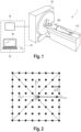
- Fig. 1 schematically shows an exemplary embodiment of a magnetic resonance imaging (MRI) system for acquisition of a magnetic resonance image.
- the system is therein denoted in its entirety by reference numeral 1.
- the MRI system 1 comprises a device 10 for determining a trajectory for acquisition of an MRI image, an MRI scanner 20 and an image reconstruction device 30.
- the device 10 for determining the trajectory for acquisition of an MRI image is adapted to determine a k-space trajectory for acquisition of k-space MRI data independent of an a-priori defined field of view, FOV.
- said k-space trajectory may comprise a field-of-view independent 3D k-space trajectory based on one or more Jacobi theta functions.
- the MRI scanner 20 can be adapted to acquire the k-space MRI data, wherein a gradient waveform corresponding to said field-of-view independent k-space trajectory is applied to magnetic field gradients of the MRI scanner.
- the MRI scanner 20 can be a commercially available MRI scanner comprising a (superconducting) magnet as well as the usual gradient coils and radio frequency coils for excitation and signal acquisition.
- the image reconstruction device 30 can comprise an interface for selecting a desired field of view for the magnetic resonance image after acquiring the k-space MRI data.
- a conventional human-machine-interface 32 for computers may be provided.
- the image reconstruction device can be adapted to construct the magnetic resonance image based on the desired field of view from the acquired k-space MRI data previously provided by the MRI scanner 20. It shall be understood that one or more of these system elements may be co-integrated.
- the device 10 and the reconstruction device 30 may be implemented in form of a control station or computer 34.
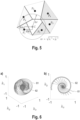
- Fig. 2 shows a diagram of conventional k-space sampling on a regular grid-pattern.
- K-space is a commonly used frequency domain representation for the acquisition of MRI data.
- the frequency domain data is then transformed into the image domain to provide an image for review by a radiologist.
- the separation ⁇ k of neighboring measurement points in frequency domain defines the size of the MRI field of view.
- the maximum value k max in turn defines the maximum resolution in the image domain.
- a rather high density of sampling points in frequency domain has to be provided, which may lead to slow signal acquisition.
- conventional MRI systems always request an operator to select a limited field of view as a first step prior to acquisition of MRI data, even if more advanced acquisition schemes such as 3D cones sampling are used.
- FOV field of view
- independent k-space trajectory in particular derived from Jacobi theta functions
- the use of Jacobi theta functions allows for a variety of highly adaptable k-space interleaves while maintaining low-coherent sampling properties.
- low-coherent aliasing properties offer the possibility of reconstructing arbitrary FOVs by only introducing random noise-like aliasing artefacts. This leads to a situation in which a MRI trajectory can be constructed by totally neglecting the desired imaging FOV. Accordingly, and FOV-independent MRI trajectory is provided based on one or more Jacobi theta functions.
- a target resolution and/or a predefined scan time can be provided as an input.
- no FOV information is required.
- the trajectory is just adapted to meet a given resolution.
- a total number of interleaves may be derived from a desired total scan duration.
- the presented concept can mark a well-suited precondition for the combination with a CS reconstruction, especially with the ability of achieving variable sampling densities around the center of k-space.
- Fig. 3b show exemplary waveforms for the three gradient.
- the horizontal axis denotes the sequence of gradient samples.
- the vertical axis denotes the gradient amplitude in arbitrary units.
- the gradient amplitude may optionally be expressed in mT/m.
- the proposed method may allow to use image information that may lie outside of the actual image region to be displayed. Moreover, the signal acquisition of 3D MRI may be accelerated.
- step S44 the k-space MRI data is acquired using the MRI scanner.
- a gradient waveform corresponding to the determined field-of-view independent k-space trajectory is applied to magnetic field gradients of the MRI scanner.
- step S45 i.e. after having acquired the k-space MRI data in step S44, a desired field of view for the magnetic resonance image is selected.
- the magnetic resonance image is constructed based on the desired field of view from the acquired k-space MRI data.
- a violation of the given sampling condition leads to aliasing i.e. interference of image information that is not represented in the acquired spatial frequency data.
- Cartesian undersampling leads to aliasing artefacts in the spatial domain known as "ghosts", while in the case of radial (polar) undersampling streak artefacts appear.
- the Delta peak is spread out which leads to a decrease in resolution in the reconstructed image.
- the full width at half maximum of the center peak of the PSFs can be seen as an appropriate measure for image sharpness also in a relative way by allowing comparisons of different PSFs, while the side-lobe behavior indicates coherent aliasing properties.
- ⁇ L 2 R 3 i.e.
- ⁇ may have a square Lebesque integrable representation
- ⁇ can allow for the introduction of a density compensation function when sampling on a non-equidistant grid.
- Such a density compensation may only influence the peak/side-lobe amplitudes in the PSFs but not their overall position.
- the undersampled region will generate aliasing artefacts within a FOV that is calculated with respect to the sampling density within the Nyquist sampled volume.
- the nature of random sampling may lead to various spacings between neighboring k-space points and therefore to the interference of a multitude of cosine waves in image space.
- the resulting pattern of interference in image space consists of numerous regions of constructive and destructive interference, spreading the aliased energies more and more homogeneous over the imaging space, as the variations in point spacings and their spatial orientations vary.
- the full width at half maximum (FWHM) of the PSFs has been found to remain widely unchanged as the undersampling factor increases, leading to a conservation of image sharpness.
- the white noise-like character may in turn be addressed with image post-processing.
- Jacobi elliptic functions can be used to describe the motion of a frictionless pendulum, where the real part of the period determines the time of the pendulum to go through one full cycle. Additionally, the imaginary period describes the same periodicity but under the transformation t ⁇ it , i.e. the sign of all forces is reversed.
- the Jacobi elliptic functions e.g. sn ( it, l ) must therefore be periodic as a function of time t and spatial variable l , making them double periodic functions.
- these traditional representations using infinite sums may optionally be transformed and adapted for an efficient numerical implementation.
- all theta functions are analytic functions for z , q ⁇ C and
- the gradient waveform can be deduced from the k-space waveform by differentiation. Assuming a k-space interleave based on theta functions leads to a steady and continuously differentiable gradient waveform which makes the latter less prone to system imperfections.
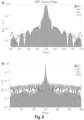
- Fig. 5 shows a schematic representation of seven Voronoi cells in a two-dimensional k-space. In the given example, six nearest neighbors of the point of interest C are used for the definition of the generalized FOV.
- the direct distances d c,Pi between C and each P i are calculated and the mean value of all six distances defines a radius ⁇ r around C.
- ⁇ r defines the radius of a sphere, from which an equal FOV along each direction is derived.
- the given definition allows the assignment of an isotropic FOV (lower bound) to various specific regions and points in k-space.
- a k-space trajectory for acquisition of k-space MRI data can be determined in particular based on one or more Jacobi theta functions such that a FOV-independent 3D k-space trajectory can be realized.
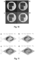
- Fig. 6a shows two different exemplary k-space waveforms of arbitrary length, for which the k x and k y components are once based on ⁇ 1 (see curve 61) and once on ⁇ 4 (see curve 62).
- a projection of both waveforms into the k x -k y -plane is shown in Fig, 6b .
- Both interleaves are shown in three-dimensional k-space in Fig. 6a and as a plane projection in Fig. 6b .
- the following exemplary waveform is meant to prove the imaging concept for a lower limit of read-out durations.
- the combination with sine and cosine terms in the first two components may allow for a modifiable change in direction per unit length while the symmetry along the z-direction may remain unchanged ( Fig. 6 ).
- the length of the waveform can be determined by s and therefore the restriction s ⁇ [0 , s max ] may be applied with s max being sufficiently large according to the desired resolution (corresponding to extension of k-space).
- the distance of each point on the spiral w.r.t. the k-space center may be linearly scaled from 0 to k max .
- the length of the spiral may be calculated to correspond to a certain read-out duration and resolution.
- the complete trajectory consisted of 20,000 rotated interleaves with a maximum gradient strength of 21 mT/m and a slew-rate of 120 T/m/s. Thereby, the total number of read-outs was arbitrarily defined and was not based on any prior FOV estimation.
- the trajectory can optionally be optimized by minimizing its discrepancy.
- the resulting read-out duration for each interleave was 3.52 ms, in order to reach the boundary of the k-space sphere for the defined maximum gradient amplitude and slew-rate limits.
- Ten interleaves of the final trajectory are depicted in Fig. 7 for illustrative purposes.
- Fig. 7 illustrates a set of ten interleaves of the exemplary 3D ⁇ -based spiral trajectory. The increased sampling density around the center of k-space can be clearly appreciated.
- the presented exemplary trajectory with 20,000 interleaves has the following properties:
- Fig. 10 shows a slice (coronal orientation) of the image quality phantom, acquired with the presented 3D ⁇ -based spiral trajectories for each undersampling factor. All data was directly gridded and no additional image or data processing was applied before and after gridding. Furthermore, no sensitivity maps were used, in order not to alter the emerging imaging artefacts.
- Fig. 10 thus shows a slice of an image quality phantom (coronal orientation), acquired for various undersampling factors R 1 in a), R 2 in b), R 3 in c) and R 4 in d).
- Each image in Fig. 10 contains a square marking that corresponds to the generalized FOV of the underlying (undersampled) trajectory of the 3D ⁇ -based spiral acquisitions.
- the generalized FOV of M 3 is z:: 67 mm (isotropic), z:: 34 mm for M 6 , z:: 24 mm for M 9 and ⁇ 17 mm for M 13 .
- the reconstruction of a larger FOV, in this case of 220 mm (isotropic) for all datasets results in additional low-coherent aliasing artefacts which can clearly be appreciated.
- all images appear non-degraded by coherent aliasing artefacts, especially visible in regions with no phantom fluid.
- image sharpness is preserved and based on the optical impression equal for all investigated undersampling factors.
- the logarithmic visualization explicitly emphasizes artefacts, arising in the background and within the regions inside the phantom, that contain no phantom fluid. Again, a steady increase in pixel intensity variations can be observed, without any obvious coherent aliasing behavior. The representation also nicely highlights the preservation of image sharpness, especially noticeable around the region of no signal within the phantom.
- Fig. 13 shows normalized power spectra for the cubic region of interest within the phantom, containing no signal.
- the normalized power spectra merely indicate slightly overpronounced DC components for all acquisitions.
- the 3D ⁇ -based Spiral trajectories (20,000 and 1,250 interleaves)
- all further spatial frequency components are about equally represented, leading to a widely flat power spectrum in accordance to the behavior of (bandwidth limited) white noise.
- an increasing undersampling factor increases the overall power but the characteristics (line-shapes) remain widely unchanged.
- ⁇ -based spirals a trajectory might be constructed just by following given time restrictions and imaging constraints, e.g. such as: (1) Size of k-space sphere is defined by the desired image resolution; (2) Maximum read-out duration (spiral length) is defined (limited) by off-resonance behavior and relaxation effects; and (3) Total acceptable scan duration defines the number of possible interleaves.
- the same Voronoi density compensation can be used for any reconstructed FOV.
- a computer program may be stored/distributed on a suitable non-transitory medium, such as an optical storage medium or a solid-state medium supplied together with or as part of other hardware, but may also be distributed in other forms, such as via the Internet or other wired or wireless telecommunication systems.
- a suitable non-transitory medium such as an optical storage medium or a solid-state medium supplied together with or as part of other hardware, but may also be distributed in other forms, such as via the Internet or other wired or wireless telecommunication systems.
Landscapes
- Physics & Mathematics (AREA)
- Engineering & Computer Science (AREA)
- General Physics & Mathematics (AREA)
- High Energy & Nuclear Physics (AREA)
- Condensed Matter Physics & Semiconductors (AREA)
- Health & Medical Sciences (AREA)
- Nuclear Medicine, Radiotherapy & Molecular Imaging (AREA)
- Radiology & Medical Imaging (AREA)
- Theoretical Computer Science (AREA)
- General Health & Medical Sciences (AREA)
- Signal Processing (AREA)
- Medical Informatics (AREA)
- Epidemiology (AREA)
- Computer Vision & Pattern Recognition (AREA)
- Primary Health Care (AREA)
- Public Health (AREA)
- Computing Systems (AREA)
- Artificial Intelligence (AREA)
- Geometry (AREA)
- Computer Graphics (AREA)
- Magnetic Resonance Imaging Apparatus (AREA)
Claims (13)
- Verfahren (40) zur Erfassung eines MRT-Bildes unabhängig von einem a-priori definierten Sichtfeld, FOV, wobei das Verfahren die Abfolge von Schritten aufweist:- Bestimmen (10, S42) einer k-Raum-Trajektorie zur Erfassung von k-Raum-MRT-Daten, wobei die k-Raum-Trajektorie kohärenzarme Aliasing-Eigenschaften aufweist und wobei die k-Raum-Trajektorie eine sichtfeld-, FOV-, unabhängige 3D k-Raum-Trajektorie aufweist, wobei die 3D k-Raum-Trajektorie zur Erfassung der k-Raum-MRT-Daten unabhängig von einem a-priori definierten Sichtfeld eines zu konstruierenden MRT-Bildes ist,- Erfassen (20, S44) von k-Raum-MRT-Daten, wobei eine Gradienten-Wellenform, die mit der sichtfeldunabhängigen k-Raum-Trajektorie korrespondier, an Magnetfeldgradienten des MRT-Scanners (20) angelegt wird; und- Auswählen (30, S45) eines gewünschten Sichtfeldes für das MRT-Bild nach dem Erfassen der k-Raum-MRT-Daten und Konstruieren des MRT-Bildes basierend auf dem gewünschten Sichtfelds aus den erfassten k-Raum-MRT-Daten.
- Verfahren nach Anspruch 1, wobei die sichtfeldunabhängige 3D k-Raum-Trajektorie auf einer oder mehreren Jacobi-Theta-Funktionen basiert.
- Verfahren nach einem der vorhergehenden Ansprüche, wobei die sichtfeldunabhängige 3D k-Raum-Trajektorie basierend auf einer gewünschten Bildauflösung bestimmt wird.
- Verfahren nach einem der vorhergehenden Ansprüche, wobei die sichtfeldunabhängige 3D k-Raum-Trajektorie basierend auf einer gewünschten Bilderfassungszeit bestimmt wird.
- Verfahren nach einem der vorhergehenden Ansprüche, wobei die sichtfeldunabhängige 3D k-Raum-Trajektorie auf mehreren Jacobi-Theta-Funktionen basiert, wobei mehreren Jacobi-Theta-Funktionen so angepasst sind, dass sie kohärenzarme Aliasing-Eigenschaften unterhalb eines vorgegebenen Schwellenwerts in dem MRT-Bild bereitstellen.
- Verfahren nach Anspruch 2 oder einem der vorhergehenden Ansprüche in Verbindung mit Anspruch 2, wobei eine oder mehrere der Jacobi-Theta-Funktionen durch mindestens eine von θ 1 , θ 2 , θ 3 , θ 4 bereitgestellt werden, wobei


- Verfahren nach einem der vorhergehenden Ansprüche, wobei die sichtfeldunabhängige 3D k-Raum-Trajektorie mehrere unterschiedliche Verschachtelungen im k-Raum basierend auf unterschiedlichen Jacobi-Theta-Funktionen aufweist.
- Verfahren nach Anspruch 7, wobei die Länge einer Verschachtelung basierend auf einer vorgegebenen Auslesezeit und/oder Auflösung bestimmt wird (S41).
- Verfahren nach Anspruch 2 oder nach einem der vorhergehenden Ansprüche in Kombination mit Anspruch 2, wobei mindestens eine der Jacobi-Theta-Funktionen von einer elliptischen Jacobi-Funktion verschieden ist.
- Verfahren nach einem der vorangehenden Ansprüche, das dazu eingerichtet ist, die k-Raum-MRT-Daten durch Abtasten des k-Raums in einer randomisierten Weise zu erfassen, insbesondere basierend auf einer oder mehreren Jacobi-Theta-Funktionen.
- Verfahren nach einem der vorhergehenden Ansprüche, wobei die Bestimmung der k-Raum-Trajektorie zur Erfassung von k-Raum-MRT-Daten das Abrufen einer oder mehrerer vorbestimmter sichtfeldunabhängiger Trajektorien aus einem Speicher (43) vorbestimmter sichtfeldunabhängiger Trajektorien aufweist.
- MRT-System (1) zur Erfassung eines MRT-Bildes, wobei das System Folgendes aufweist:- eine Vorrichtung (10) zum Bestimmen einer Trajektorie zur Erfassung eines MRT-Bildes, wobei die Vorrichtung (10) dazu eingerichtet ist, um eine 3D k-Raum-Trajektorie zur Erfassung von k-Raum-MRT-Daten zu bestimmen, wobei die k-Raum-Trajektorie kohärenzarme Aliasing-Eigenschaften aufweist und unabhängig von einem a-priori definierten Sichtfeld, FOV, ist, wobei die 3D k-Raum-Trajektorie zur Erfassung der k-Raum-MRT-Daten unabhängig von einem a-priori definierten Sichtfeld des MRT-Bildes ist, insbesondere wobei die k-Raum-Trajektorie eine sichtfeldunabhängige 3D k-Raum-Trajektorie basierend auf einer oder mehreren Jacobi-Theta-Funktionen aufweist;- einen MRT-Scanner (20), der dazu eingerichtet ist k-Raum-MRT-Daten zu erfassen, wobei eine Gradienten-Wellenform, die mit der sichtfeldunabhängigen k-Raum-Trajektorie korrespondiert, an Magnetfeldgradienten des MRT-Scanners (20) angelegt wird; und- eine Bildrekonstruktionsvorrichtung (30), die ein interface zum Auswählen eines gewünschten Sichtfeldes für das MRT-Bild nach dem Erfassen der k-Raum-MRT-Daten aufweist und dazu eingerichtet ist, das MRT-Bild basierend auf dem gewünschten Sichtfelds aus den erfassten k-Raum-MRT-Daten zu konstruieren.
- Computerprogramm, das Programmcodemittel aufweist, um einen Computer dazu zu veranlassen, eine 3D k-Raum-Trajektorie zur Erfassung von k-Raum-MRT-Daten zu bestimmen, wobei die k-Raum-Trajektorie kohärenzarme Aliasing-Eigenschaften aufweist und unabhängig von einem a-priori definierten Sichtfeld, FOV, ist, wobei die 3D k-Raum-Trajektorie zur Erfassung der k-Raum-MRT-Daten unabhängig von einem a-priori definierten Sichtfeld des MRT-Bildes ist, und das, wenn es auf einem MRT-System ausgeführt wird, das MRT-System dazu veranlasst, die Datenerfassung mit der ausgewählten k-Raum-Trajektorie durchzuführen; und dazu eingerichtet ist, um, basierend auf einem nach dem Erfassen der k-Raum-MRT-Daten über ein Interface ausgewählten gewünschten Sichtfeld für das MRT-Bild, das MRT-Bild basierend auf dem gewünschten Sichtfeld aus den erfassten k-Raum-MRT-Daten zu konstruieren.
Applications Claiming Priority (2)
| Application Number | Priority Date | Filing Date | Title |
|---|---|---|---|
| EP21160759.3A EP4053580A1 (de) | 2021-03-04 | 2021-03-04 | System und verfahren zur erfassung eines magnetresonanzbildes sowie vorrichtung zur bestimmung einer trajektorie zur erfassung eines magnetresonanzbildes |
| PCT/EP2022/055348 WO2022184808A1 (en) | 2021-03-04 | 2022-03-03 | System and method for acquisition of a magnetic resonance image as well as device for determining a trajectory for acquisition of a magnetic resonance image |
Publications (3)
| Publication Number | Publication Date |
|---|---|
| EP4302111A1 EP4302111A1 (de) | 2024-01-10 |
| EP4302111B1 true EP4302111B1 (de) | 2025-02-26 |
| EP4302111C0 EP4302111C0 (de) | 2025-02-26 |
Family
ID=74858361
Family Applications (2)
| Application Number | Title | Priority Date | Filing Date |
|---|---|---|---|
| EP21160759.3A Withdrawn EP4053580A1 (de) | 2021-03-04 | 2021-03-04 | System und verfahren zur erfassung eines magnetresonanzbildes sowie vorrichtung zur bestimmung einer trajektorie zur erfassung eines magnetresonanzbildes |
| EP22710058.3A Active EP4302111B1 (de) | 2021-03-04 | 2022-03-03 | System und verfahren zur erfassung eines magnetresonanzbildes sowie vorrichtung zur bestimmung einer trajektorie zur erfassung eines magnetresonanzbildes |
Family Applications Before (1)
| Application Number | Title | Priority Date | Filing Date |
|---|---|---|---|
| EP21160759.3A Withdrawn EP4053580A1 (de) | 2021-03-04 | 2021-03-04 | System und verfahren zur erfassung eines magnetresonanzbildes sowie vorrichtung zur bestimmung einer trajektorie zur erfassung eines magnetresonanzbildes |
Country Status (3)
| Country | Link |
|---|---|
| US (1) | US20230408614A1 (de) |
| EP (2) | EP4053580A1 (de) |
| WO (1) | WO2022184808A1 (de) |
Families Citing this family (1)
| Publication number | Priority date | Publication date | Assignee | Title |
|---|---|---|---|---|
| US20240054699A1 (en) * | 2022-08-14 | 2024-02-15 | Technion Research & Development Foundation Limited | Physically-primed deep-neural-networks for generalized undersampled mri reconstruction |
-
2021
- 2021-03-04 EP EP21160759.3A patent/EP4053580A1/de not_active Withdrawn
-
2022
- 2022-03-03 EP EP22710058.3A patent/EP4302111B1/de active Active
- 2022-03-03 WO PCT/EP2022/055348 patent/WO2022184808A1/en not_active Ceased
-
2023
- 2023-08-30 US US18/240,038 patent/US20230408614A1/en active Pending
Also Published As
| Publication number | Publication date |
|---|---|
| US20230408614A1 (en) | 2023-12-21 |
| WO2022184808A1 (en) | 2022-09-09 |
| EP4302111C0 (de) | 2025-02-26 |
| EP4053580A1 (de) | 2022-09-07 |
| EP4302111A1 (de) | 2024-01-10 |
Similar Documents
| Publication | Publication Date | Title |
|---|---|---|
| CN103124517B (zh) | Mri图像的多维迭代相位循环重构 | |
| US10768260B2 (en) | System and method for controlling noise in magnetic resonance imaging using a local low rank technique | |
| Otazo et al. | Low‐rank plus sparse matrix decomposition for accelerated dynamic MRI with separation of background and dynamic components | |
| US10317499B2 (en) | MRI with repeated K-T-sub-sampling and artifact minimization allowing for free breathing abdominal MRI | |
| US9482732B2 (en) | MRI reconstruction with motion-dependent regularization | |
| US9317917B2 (en) | Method, reconstruction device, and magnetic resonance apparatus for reconstructing magnetic resonance raw data | |
| Addy et al. | High‐resolution variable‐density 3D cones coronary MRA | |
| Küstner et al. | MR image reconstruction using a combination of compressed sensing and partial Fourier acquisition: ESPReSSo | |
| US8948480B2 (en) | Image reconstruction using redundant Haar wavelets | |
| CN104379058A (zh) | 用于高分辨率mri合并复用灵敏度编码(muse)的多重拍摄扫描协议 | |
| Liu et al. | High-performance rapid MR parameter mapping using model-based deep adversarial learning | |
| CN105143906A (zh) | 金属抗mr成像 | |
| Jun et al. | Zero‐DeepSub: zero‐shot deep subspace reconstruction for rapid multiparametric quantitative MRI using 3D‐QALAS | |
| CN113298901A (zh) | 卷褶视野磁共振图像的重建方法、计算机设备及存储介质 | |
| Mickevicius et al. | Simultaneous acquisition of orthogonal plane cine imaging and isotropic 4D-MRI using super-resolution | |
| US9689947B2 (en) | Sampling strategies for sparse magnetic resonance image reconstruction | |
| Qiu et al. | Self‐calibrated subspace reconstruction for multidimensional MR fingerprinting for simultaneous relaxation and diffusion quantification | |
| WO2019147927A1 (en) | Synthetic three-dimensional magnetic resonance imaging | |
| US12298373B2 (en) | Propeller magnetic resonance acquisition and blade-specific reconstruction | |
| US20230408614A1 (en) | System and method for acquisition of a magnetic resonance image as well as device for determining a trajectory for acquisition of a magnetic resonance image | |
| US10818047B2 (en) | Iterative reconstruction of quantitative magnetic resonance images | |
| CN114062988B (zh) | 磁共振波谱成像方法、装置、计算机设备和存储介质 | |
| Li et al. | Sub-second whole brain T2 mapping via multiband SENSE multiple overlapping-echo detachment imaging and deep learning | |
| US12153110B2 (en) | Simultaneous multi-slice MRSI using density weighted concentric ring acquisition | |
| CN116953582A (zh) | 磁共振成像设备的多个线圈灵敏度图和sense重建 |
Legal Events
| Date | Code | Title | Description |
|---|---|---|---|
| STAA | Information on the status of an ep patent application or granted ep patent |
Free format text: STATUS: UNKNOWN |
|
| STAA | Information on the status of an ep patent application or granted ep patent |
Free format text: STATUS: THE INTERNATIONAL PUBLICATION HAS BEEN MADE |
|
| PUAI | Public reference made under article 153(3) epc to a published international application that has entered the european phase |
Free format text: ORIGINAL CODE: 0009012 |
|
| STAA | Information on the status of an ep patent application or granted ep patent |
Free format text: STATUS: REQUEST FOR EXAMINATION WAS MADE |
|
| 17P | Request for examination filed |
Effective date: 20230904 |
|
| AK | Designated contracting states |
Kind code of ref document: A1 Designated state(s): AL AT BE BG CH CY CZ DE DK EE ES FI FR GB GR HR HU IE IS IT LI LT LU LV MC MK MT NL NO PL PT RO RS SE SI SK SM TR |
|
| DAV | Request for validation of the european patent (deleted) | ||
| DAX | Request for extension of the european patent (deleted) | ||
| GRAP | Despatch of communication of intention to grant a patent |
Free format text: ORIGINAL CODE: EPIDOSNIGR1 |
|
| STAA | Information on the status of an ep patent application or granted ep patent |
Free format text: STATUS: GRANT OF PATENT IS INTENDED |
|
| INTG | Intention to grant announced |
Effective date: 20240923 |
|
| GRAS | Grant fee paid |
Free format text: ORIGINAL CODE: EPIDOSNIGR3 |
|
| GRAA | (expected) grant |
Free format text: ORIGINAL CODE: 0009210 |
|
| STAA | Information on the status of an ep patent application or granted ep patent |
Free format text: STATUS: THE PATENT HAS BEEN GRANTED |
|
| AK | Designated contracting states |
Kind code of ref document: B1 Designated state(s): AL AT BE BG CH CY CZ DE DK EE ES FI FR GB GR HR HU IE IS IT LI LT LU LV MC MK MT NL NO PL PT RO RS SE SI SK SM TR |
|
| REG | Reference to a national code |
Ref country code: GB Ref legal event code: FG4D |
|
| REG | Reference to a national code |
Ref country code: CH Ref legal event code: EP |
|
| REG | Reference to a national code |
Ref country code: DE Ref legal event code: R096 Ref document number: 602022011132 Country of ref document: DE |
|
| REG | Reference to a national code |
Ref country code: IE Ref legal event code: FG4D |
|
| PGFP | Annual fee paid to national office [announced via postgrant information from national office to epo] |
Ref country code: AT Payment date: 20250417 Year of fee payment: 4 |
|
| U01 | Request for unitary effect filed |
Effective date: 20250325 |
|
| U07 | Unitary effect registered |
Designated state(s): AT BE BG DE DK EE FI FR IT LT LU LV MT NL PT RO SE SI Effective date: 20250331 |
|
| PG25 | Lapsed in a contracting state [announced via postgrant information from national office to epo] |
Ref country code: RS Free format text: LAPSE BECAUSE OF FAILURE TO SUBMIT A TRANSLATION OF THE DESCRIPTION OR TO PAY THE FEE WITHIN THE PRESCRIBED TIME-LIMIT Effective date: 20250526 |
|
| PG25 | Lapsed in a contracting state [announced via postgrant information from national office to epo] |
Ref country code: PL Free format text: LAPSE BECAUSE OF FAILURE TO SUBMIT A TRANSLATION OF THE DESCRIPTION OR TO PAY THE FEE WITHIN THE PRESCRIBED TIME-LIMIT Effective date: 20250226 |
|
| PG25 | Lapsed in a contracting state [announced via postgrant information from national office to epo] |
Ref country code: ES Free format text: LAPSE BECAUSE OF FAILURE TO SUBMIT A TRANSLATION OF THE DESCRIPTION OR TO PAY THE FEE WITHIN THE PRESCRIBED TIME-LIMIT Effective date: 20250226 |
|
| PG25 | Lapsed in a contracting state [announced via postgrant information from national office to epo] |
Ref country code: NO Free format text: LAPSE BECAUSE OF FAILURE TO SUBMIT A TRANSLATION OF THE DESCRIPTION OR TO PAY THE FEE WITHIN THE PRESCRIBED TIME-LIMIT Effective date: 20250526 Ref country code: IS Free format text: LAPSE BECAUSE OF FAILURE TO SUBMIT A TRANSLATION OF THE DESCRIPTION OR TO PAY THE FEE WITHIN THE PRESCRIBED TIME-LIMIT Effective date: 20250626 |
|
| PG25 | Lapsed in a contracting state [announced via postgrant information from national office to epo] |
Ref country code: HR Free format text: LAPSE BECAUSE OF FAILURE TO SUBMIT A TRANSLATION OF THE DESCRIPTION OR TO PAY THE FEE WITHIN THE PRESCRIBED TIME-LIMIT Effective date: 20250226 |
|
| PG25 | Lapsed in a contracting state [announced via postgrant information from national office to epo] |
Ref country code: GR Free format text: LAPSE BECAUSE OF FAILURE TO SUBMIT A TRANSLATION OF THE DESCRIPTION OR TO PAY THE FEE WITHIN THE PRESCRIBED TIME-LIMIT Effective date: 20250527 |
|
| U20 | Renewal fee for the european patent with unitary effect paid |
Year of fee payment: 4 Effective date: 20250623 |
|
| PG25 | Lapsed in a contracting state [announced via postgrant information from national office to epo] |
Ref country code: SM Free format text: LAPSE BECAUSE OF FAILURE TO SUBMIT A TRANSLATION OF THE DESCRIPTION OR TO PAY THE FEE WITHIN THE PRESCRIBED TIME-LIMIT Effective date: 20250226 |
|
| PG25 | Lapsed in a contracting state [announced via postgrant information from national office to epo] |
Ref country code: CZ Free format text: LAPSE BECAUSE OF FAILURE TO SUBMIT A TRANSLATION OF THE DESCRIPTION OR TO PAY THE FEE WITHIN THE PRESCRIBED TIME-LIMIT Effective date: 20250226 |
|
| REG | Reference to a national code |
Ref country code: CH Ref legal event code: H13 Free format text: ST27 STATUS EVENT CODE: U-0-0-H10-H13 (AS PROVIDED BY THE NATIONAL OFFICE) Effective date: 20251023 |
|
| PG25 | Lapsed in a contracting state [announced via postgrant information from national office to epo] |
Ref country code: SK Free format text: LAPSE BECAUSE OF FAILURE TO SUBMIT A TRANSLATION OF THE DESCRIPTION OR TO PAY THE FEE WITHIN THE PRESCRIBED TIME-LIMIT Effective date: 20250226 |
|
| PG25 | Lapsed in a contracting state [announced via postgrant information from national office to epo] |
Ref country code: MC Free format text: LAPSE BECAUSE OF FAILURE TO SUBMIT A TRANSLATION OF THE DESCRIPTION OR TO PAY THE FEE WITHIN THE PRESCRIBED TIME-LIMIT Effective date: 20250226 |
|
| PLBE | No opposition filed within time limit |
Free format text: ORIGINAL CODE: 0009261 |
|
| STAA | Information on the status of an ep patent application or granted ep patent |
Free format text: STATUS: NO OPPOSITION FILED WITHIN TIME LIMIT |
|
| PG25 | Lapsed in a contracting state [announced via postgrant information from national office to epo] |
Ref country code: CH Free format text: LAPSE BECAUSE OF NON-PAYMENT OF DUE FEES Effective date: 20250331 |
|
| PG25 | Lapsed in a contracting state [announced via postgrant information from national office to epo] |
Ref country code: IE Free format text: LAPSE BECAUSE OF NON-PAYMENT OF DUE FEES Effective date: 20250303 |
|
| 26N | No opposition filed |
Effective date: 20251127 |
|
| PGFP | Annual fee paid to national office [announced via postgrant information from national office to epo] |
Ref country code: GB Payment date: 20260324 Year of fee payment: 5 |