EP4302485B1 - Verfahren zum zentralen synchronisieren der ausführung von anweisungen durch peripheriegeräte eines drahtlosen netzwerks und system, das das verfahren implementiert - Google Patents
Verfahren zum zentralen synchronisieren der ausführung von anweisungen durch peripheriegeräte eines drahtlosen netzwerks und system, das das verfahren implementiert Download PDFInfo
- Publication number
- EP4302485B1 EP4302485B1 EP22708239.3A EP22708239A EP4302485B1 EP 4302485 B1 EP4302485 B1 EP 4302485B1 EP 22708239 A EP22708239 A EP 22708239A EP 4302485 B1 EP4302485 B1 EP 4302485B1
- Authority
- EP
- European Patent Office
- Prior art keywords
- peripheral
- training
- instruction
- time
- time stamp
- Prior art date
- Legal status (The legal status is an assumption and is not a legal conclusion. Google has not performed a legal analysis and makes no representation as to the accuracy of the status listed.)
- Active
Links
Images





Classifications
-
- H—ELECTRICITY
- H04—ELECTRIC COMMUNICATION TECHNIQUE
- H04Q—SELECTING
- H04Q9/00—Arrangements in telecontrol or telemetry systems for selectively calling a substation from a main station, in which substation desired apparatus is selected for applying a control signal thereto or for obtaining measured values therefrom
- H04Q9/04—Arrangements for synchronous operation
-
- H—ELECTRICITY
- H04—ELECTRIC COMMUNICATION TECHNIQUE
- H04W—WIRELESS COMMUNICATION NETWORKS
- H04W56/00—Synchronisation arrangements
- H04W56/0055—Synchronisation arrangements determining timing error of reception due to propagation delay
- H04W56/0065—Synchronisation arrangements determining timing error of reception due to propagation delay using measurement of signal travel time
-
- H—ELECTRICITY
- H04—ELECTRIC COMMUNICATION TECHNIQUE
- H04J—MULTIPLEX COMMUNICATION
- H04J3/00—Time-division multiplex systems
- H04J3/02—Details
- H04J3/06—Synchronising arrangements
- H04J3/0635—Clock or time synchronisation in a network
- H04J3/0638—Clock or time synchronisation among nodes; Internode synchronisation
- H04J3/0658—Clock or time synchronisation among packet nodes
- H04J3/0661—Clock or time synchronisation among packet nodes using timestamps
- H04J3/0667—Bidirectional timestamps, e.g. NTP or PTP for compensation of clock drift and for compensation of propagation delays
-
- H—ELECTRICITY
- H04—ELECTRIC COMMUNICATION TECHNIQUE
- H04Q—SELECTING
- H04Q2209/00—Arrangements in telecontrol or telemetry systems
- H04Q2209/10—Arrangements in telecontrol or telemetry systems using a centralized architecture
-
- H—ELECTRICITY
- H04—ELECTRIC COMMUNICATION TECHNIQUE
- H04Q—SELECTING
- H04Q2209/00—Arrangements in telecontrol or telemetry systems
- H04Q2209/40—Arrangements in telecontrol or telemetry systems using a wireless architecture
- H04Q2209/43—Arrangements in telecontrol or telemetry systems using a wireless architecture using wireless personal area networks [WPAN], e.g. 802.15, 802.15.1, 802.15.4, Bluetooth® or Zigbee®
-
- H—ELECTRICITY
- H04—ELECTRIC COMMUNICATION TECHNIQUE
- H04Q—SELECTING
- H04Q2209/00—Arrangements in telecontrol or telemetry systems
- H04Q2209/80—Arrangements in the sub-station, i.e. sensing device
- H04Q2209/84—Measuring functions
- H04Q2209/845—Measuring functions where the measuring is synchronized between sensing devices
Definitions
- the present invention relates to a method for centrally synchronising the execution of instructions by peripheral devices of a wireless network and to a system that implements the method.
- portable electronic devices such as smartphones, laptops and smartwatches may be connected to each other to form a wireless network, e.g. via well-known protocols such as Wi-Fi and Bluetooth.
- a wireless network may consist of a plurality of measuring devices and a central device, which typically has more advanced hardware resources, e.g. in terms of memory and computing power, than the measuring devices.
- Measuring devices comprise embedded sensors and actuators such as accelerometers, gyroscopes, etc., e.g. MEMS, which are configured to acquire electrical signals as a function of one or more physical quantities (e.g. accelerations) and send them to the central device.
- the central device is configured to process the signals received from the measuring devices.
- the central device may be a smartphone and the measuring devices may be wearable devices such as smartwatches, which are placed in contact with different parts of a user's body.
- Such measuring devices can detect physical quantities representative of the user's movement and send the acquired data over time to the central device, which can process it to determine a movement profile of the user, e.g. to monitor or identify different activities such as running, swimming etc.
- the central device and the measuring devices each comprise a respective clock, e.g. a free-running clock, e.g. obtained from an electronic oscillator, or a derivative, such as a phase-lock loop, which regulates the operating frequency thereof.
- a respective clock e.g. a free-running clock, e.g. obtained from an electronic oscillator, or a derivative, such as a phase-lock loop, which regulates the operating frequency thereof.
- data acquired by the measuring devices also have asynchronies that can cause errors during the subsequent relative processing by the central device.
- Such variations may be difficult to identify and therefore difficult to prevent or compensate for, as they can be further affected, for example, by transmission delays due to the wireless connection channel and delays of hardware or software origin inside electronic devices.
- Document EP 3 573 386 A1 discloses the synchronizing of data packets from embedded data sensors monitoring body motion of a patient, in particular data packets transmitted by a Bluetooth protocol. Data packets come with a timestamp.
- a need is therefore perceived for a method for centrally synchronizing the execution of instructions by peripheral devices of a wireless network, which can compensate, in use, for such asynchronies.
- Aim of the present invention is to provide a synchronization method capable of fulfilling at least partially the above requirement.
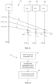
- FIG. 1 schematically shows a measurement system 1 comprising a main electronic device, hereinafter central device 5, e.g. a smartphone or laptop, and a plurality of electronic measuring devices, hereinafter measuring devices 10, e.g. wearable devices such as smart watches, augmented reality glasses, etc.
- central device 5 e.g. a smartphone or laptop
- measuring devices 10 e.g. wearable devices such as smart watches, augmented reality glasses, etc.
- the plurality of measuring devices 10 includes a first, a second and a third measuring device 10A, 10B, 10C, which are equal to each other.
- the measuring devices 10 are each configured to communicate with the central device 5 via a wireless connection channel, for example via a Bluetooth, Wi-Fi or other type of connection.
- the central device 5 is configured to send measurement instructions, such as start and end instructions of a data acquisition interval, to the measuring devices 10; the measuring devices 10 are configured to receive and execute such measurement instructions.
- the measuring devices 10 are configured to send the data acquired during each data acquisition interval to the central device 5; the central device 5 is configured to receive such acquired data for further processing.
- the measurement system 1 is configured such that the central device 5 is able to determine a plurality of delays ⁇ i (one for each measuring device 10), with which sending a plurality of measurement packets P k , each one comprising a respective measurement instruction, to the measuring devices 10, so that the measurement instructions are executed substantially simultaneously by the measuring devices 10 and thereby compensating for any asynchronies between the measuring devices 10.
- the central device 5 comprises a control unit 13, a transceiver module 15 and a synchronisation unit 17, operatively coupled to each other.
- the transceiver module 15 is configured to exchange, i.e. send and receive, data packets with the measuring devices 10.
- the transceiver module 15 additionally comprises a buffer 20.
- the control unit 13 includes at least one processing unit 21, a memory 22 and a clock 23, which are coupled with each other (although this is not shown in Figure 1 ).
- the clock 23 is any type of electronic oscillator, derived from or based on quartz oscillators, such as a voltage-controlled oscillator, and determines the frequency of the operations performed by the central device 5.
- the clock 23 comprises a respective clock register 24, wherein the current value of a counter associated with the operation of the clock 23 is stored, which is indicative of time elapsing in the time reference system of the central device 5.
- the control unit 13 is configured to read packets received by the transceiver module 15 from the measuring devices 10, and to send data to the transceiver module 15 to be included in packets that are sent to the measuring devices 10.
- the synchronisation unit 17 is configured to determine the aforementioned delays ⁇ i , by which the transceiver module 15 sends the measurement packets P k , comprising the measurement instructions, to the measuring devices 10, according to the method described in detail hereinafter.
- the measuring devices 10 each comprise a respective control unit 26, a respective transceiver module 27 and a respective detection unit 28, operatively coupled to each other.
- the first, second and third measuring devices 10A, 10B, 10C are equal to each other; therefore, for simplicity, the control units 26, the transceiver modules 27 and the detection units 28 of the first, second and third measuring devices 10A, 10B, 10C are respectively denoted by the same reference numbers.
- the transceiver module 27 of each measuring device 10 is configured to exchange, i.e. send and receive, data packets with the central device 5.
- the detection unit 28 of each measuring device 10 comprises one or more sensors, for example an accelerometer and/or a gyroscope or other type of sensor, and is configured to detect one or more physical quantities associated with the use of the respective measuring device 10 and generate a corresponding electrical signal indicative of such measured quantities.
- each detection unit 28 is configured to acquire samples of the corresponding quantity over time.
- the control unit 26 of each measuring device 10 includes at least one processing unit 29 and a memory 30 and also includes a respective clock 31, which determines the operating frequency of the respective measuring device 10.
- the clock 31 may be any type of electronic oscillator, derived from or based on quartz oscillators, e.g. a voltage-controlled oscillator, such as a free-running clock.
- the clock 31 of each measuring device 10 comprises a respective clock register 32, where the current value of a counter associated with the operation of the clock 31 is stored, which is indicative of the time elapsing in the time reference system of the corresponding measuring device 10.
- the processing unit 29, the memory 30 and the clock 31 of each measuring device 10 are coupled with each other.
- the measuring devices 10 are configured to operate at an equal nominal operating frequency.
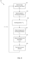
- the measurement system 1 is configured to execute the synchronisation method denoted by number 35 and schematically shown by the flowchart in Figure 2 and the diagram in Figure 3 .
- the subscript "i" is used as an index to refer indistinctly, and without losing generality, to any one of the first, second and third measuring devices 10A, 10B, 10C.
- Figure 3 refers only to a generic i-th measuring device 10.
- the synchronization method 35 is formed by a plurality of measurement cycles, one of which is shown in Figures 2 and 3 , which are equal to each other; hereinafter, these cycles are indexed by means of a k index.
- a corresponding measurement instruction is associated with it, which is sent, by insertion in a corresponding measurement packet P k , from the central device 5 to the measuring devices 10, and which is intended to be executed substantially simultaneously by the measuring devices 10.
- the measurement instruction may be, for example, an instruction for the detection unit 28 of each measuring device 10 to command, for example, a start or an end of a data acquisition interval, that is to command storing in the memory 30 of the samples acquired by the detection unit 28 in the data acquisition interval, in view of a later transmission of the stored samples to the central device 5.
- the measurement instruction may consist in an instruction which, when executed by the measuring device 10, causes the start or end of storage of the acquired samples.
- the measurement instruction may be an instruction that commands the positioning of a time mark in the memory 30 (and, therefore, among the samples acquired during the data acquisition interval) of the measuring devices 10, upon request by a user.
- a time mark marks the sample of the corresponding quantity acquired by the detection unit 28; such information may be used later, for example during a subsequent processing, by the central device 5, of the data acquired by the measuring devices 10.
- the k-th measurement cycle comprises the execution of a sequence of cycle instructions 36, as described in detail hereinafter.
- the sequence of cycle instructions 36 comprises executing: a central time stamp instruction (block INS1), a first local time stamp instruction (block INS2), a measurement instruction (block INS3) comprising one of the aforementioned measurement instructions, and a second local time stamp instruction (block INS4).
- the first local time stamp instruction, the instruction to be synchronized and the second local time stamp instruction are each associated with an instruction to send, to the measuring devices 10, a plurality of first time packets T1, a plurality of measurement packets P k , and, respectively, a plurality of second time packets T2.
- the first time packets T1, the second time packets T2 and the measurement packets P k may be placed one after the other in the buffer 20, so that these packets are sent in sequence to each other when specific conditions occur.
- the k-th measurement cycle of the synchronization method 35 is triggered by the reception, at instant t 1 , by the central device 5, in particular by the control unit 13, of a measurement command from a user of the measurement system 1, i.e. when the user commands the execution of a measurement instruction.
- the central device 5 can be commanded by the user so as to allow the latter to send the aforementioned measurement command to the control unit 13, and thus cause the execution of the corresponding measurement instruction.
- a step S1 follows, wherein the central device 5 determines a reference time stamp T MD (k), as described hereinafter.
- the control unit 13 executes the above-mentioned central time stamp instruction (block INS1 of Figure 4 ), which commands the reading, by the control unit 13 of the central device 5, of the current value in the respective clock register 24.
- the control unit 13 stores the reference time stamp T MD (k) in the respective memory 22.
- the central device 5 in particular the respective control unit 13, causes the determination of a plurality of first measurement time stamps t i,t1 , one for each measuring device 10, as described below.
- control unit 13 executes the aforementioned instruction to send a plurality of first time packets T1 and the central device 5 simultaneously sends, at the instant t st1 , a plurality of first time packets T1, one for each measuring device 10.
- control unit 13 of the central device 5 may be configured to generate a first control signal after reading and storing of the reference time stamp T MD (k).
- the first control signal commands the execution of the instruction to send a plurality of first time packets T1.
- the first time packets T1 each include the first local time stamp instruction, which is the same for each first time packet T1.
- the first time packets T1 have the same payload, which comprises the first local time stamp instruction, and differ from each other in the address of the measuring device 10 to which each one is delivered.
- the measuring devices 10 each receive their respective first time packet T1 at respective instants t i,rt1 .
- the first measuring device 10A receives the respective first time packet T1 at an instant t 1,rt1 .
- the time difference between the instant t st1 and the instant t 1,rt1 depends on multiple factors, such as the physical distance between the central device 5 and the first measuring device 10A and the quality of the wireless connection channel.
- the control unit 26 of each measuring device 10 is configured to process the respective first time packet T1 and execute the first local time stamp instruction (block INS2 in Figure 4 ).
- the first local time stamp instruction causes the control unit 26 of each measuring device 10 to determine the respective first measurement time stamp t i,t1 .
- the first measurement time stamp t i,t1 of a measuring device 10 corresponds to the current time, in the time reference system of the central device 10, at which the first local time stamp instruction is executed.
- the first local time stamp instruction commands the reading, by the control unit 26, of the current value in the respective clock register 32.
- the first, second and third measuring devices 10A-10C each send to the central device 5, each at a respective instant t i,a1 , a respective first acknowledgement packet AC1, the payload of which comprises the respective first measurement time stamp t i,t1 .
- the central device 5 After receiving the first acknowledgement packets AC1, the central device 5, in particular the respective control unit 13, stores the first measurement time stamps t i,t1 in the respective memory 22.
- the instant t ra1 in Figure 3 indicates the instant when the central device 5 has received the last of the first acknowledgement packets AC1.
- the time difference between the instant t 1,rt1 when the transceiver module 27 of the first measuring device 10A receives the respective first time packet T1 and the instant when the central device 5 receives the first acknowledgement packet AC1 from the first measuring device 10A depends on multiple factors, such as the quality of the connection channel, delays in executing instructions, having a software, hardware or different origin.
- the aforesaid time difference may vary between the first, second and third measuring devices 10A-10C, e.g. due to different operating conditions, differences between the respective connection channels with the central device 5, etc.
- the measuring devices 10 each execute the measurement instruction (block INS3 of Figure 4 ), after receiving, at an instant t i,rc1 , the respective measurement packet P k , in a respective execution window EW i .
- the execution windows Ewi i of each of the first, second and third measuring devices 10A, 10B, 10C may have variable durations, since they each depend on the respective clock 31.
- the measurement packets P k are sent after the central device 5 has received the first acknowledgement packets AC1 of each of the first, second and third measuring devices 10A-10C.
- the control unit 13 of the central device 5 may be configured to generate a second control signal after receiving, at the instant t ra1 , all the first acknowledgement packets AC1.
- the second control signal commands the execution, at a send instant ts, of the instruction to send the measurement packets P k .
- the central device 5 is configured to send the measurement packets P k each with a respective delay ⁇ i (k) with respect to the send instant t s .
- the delays ⁇ i (k) are stored in the central device 5, e.g. in the memory 22 of the respective control unit 13, and are determined by the central device 5, in particular the synchronization unit 17, in the k-1-th measurement cycle, as explained in detail below.
- the central device 5 sends the respective measurement packet P k to the first measuring device 10A with a first delay ⁇ 1 (k), to the second measurement device 10B with a second delay ⁇ 2 (k) and to the third measurement device 10C with a third delay ⁇ 3 (k), herein according to the relation ⁇ 3 > ⁇ 1 > ⁇ 2 .
- the first, second and third delays ⁇ 1 (k), ⁇ 2 (k), ⁇ 3 (k) cause the measurement instruction (such as the instruction causing the start or end of storing the acquired samples or the instruction commanding the positioning of a mark), to be executed substantially simultaneously by the first, second and third measuring devices 10A-10C.
- the first, second and third delays ⁇ 1 (k), ⁇ 2 (k), ⁇ 3 (k) are such that the execution windows EW 1 , EW 2 , EW 3 of the first, second and third measuring devices 10A, 10B, 10C, respectively, are substantially aligned with each other in time.
- the measuring devices 10 After the measuring devices 10 have executed the measurement instruction, the measuring devices 10 each send a respective second acknowledgement packet AC2 to the central device 5 at a respective instant t i,a2 .
- the instant t ra2 in Figure 3 indicates the instant when the central device 5 has received the last of the second acknowledgement packets AC2 from the measuring devices 10.
- a step S4 follows, wherein the central device 5, in particular the respective control unit 13, causes the determination of a plurality of second measurement time stamps t i,t2 , one for each measuring device 10.
- control unit 13 executes the instruction to send a plurality of second time packets T2 and the central device 5 simultaneously sends, at the instant t st2 , a plurality of second time packets T2, one for each measuring device 10.
- control unit 13 of the central device 5 may be configured to generate a third control signal after the reception of all the second acknowledgement packets AC2.
- the third control signal commands the execution of the instruction to send a plurality of second time packets T2.
- the second time packets T2 are the same as the first time packets T1 and each comprise the second local time stamp instruction, which is the same for each second time packet T2.
- the second time packets T2 also have the same payload between each other, which comprises the second local time stamp instruction, and differ from each other in the address of the measuring device 10 to which each one is delivered.
- the measuring devices 10 each receive their respective second time packet T2 at a respective instant t i,rt2 .
- the first measuring device 10A receives the respective second time packet T2 at an instant t 1,rt2 .
- the time difference between the instant t st2 and the instant t 1,rt2 depends on several factors, such as the physical distance between the central device 5 and the first measuring device 10A and the quality of the wireless connection channel.
- the control unit 26 of each measuring device 10 is configured to process the second time packet T2 and execute the second local time stamp instruction (block INS4 of Figure 4 ).
- the second local time stamp instruction causes the control unit 26 of each measuring device 10 to determine a respective second measurement time stamp t i,t2 .
- the second measurement time stamp t i,t2 of a measuring device 10 corresponds to the current time, in the time reference system of the respective measuring device 10, at which the second local time stamp instruction is executed.
- the second local time stamp instruction commands the reading, by the control unit 26, of the current value in the respective clock register 32.
- the first, second and third measuring devices 10A-10C send to the central device 5, each at a respective instant t i,a3 , respective third acknowledgement packets AC3, the payloads of which comprise respective second measurement time stamps t i,t2 .
- the central device 5 After reception of the third acknowledgement packets AC3, the central device 5, in particular the respective control unit 13, stores the second measurement time stamps t i,t2 in the respective memory 22.
- the instant t ra3 of Figure 3 indicates the instant when the central device 5 has received the last of the third acknowledgement packets AC3.
- a step S5 follows, wherein the central device 5, and in particular the synchronization unit 17, determines, from the first measurement time stamps t i,t1 and the second measurement time stamps t i,t2 received in the k-th measurement cycle, a plurality of delays ⁇ i (k+1) using a neural network 38, shown in Figure 7 , as described in more detail hereinafter.
- the delays ⁇ i (k+1) are used by the central device 5 in the following k+1-th measurement cycle to send the measurement packets P k+1 to the measuring devices 10.
- a cycle interval ⁇ T c which can be selected by a user depending on the specific application, i.e. depending on the desired time distance between two successive measurement instructions, the k+1-th measurement cycle is executed, as described above in relation to the k-th measurement cycle.
- the step S5 of each k-th measurement cycle comprises a plurality of steps S6-S8.
- the synchronization unit 17 is configured to determine a plurality of time parameters I i (k), one for each measuring device 10.
- the synchronization unit 17 provides the time parameters I i (k) as input to the neural network 38, which processes the time parameters I i (k), as discussed hereinafter.
- the time parameter I i (k) of each measuring device 10 is a function of the respective first measurement time stamp t i,t1 and the respective second measurement time stamp t i,t2 , determined in the k-th measurement cycle.
- the time parameters I i (k) may each be given by the sum of the respective first measurement time stamp t i,t1 and the respective second measurement time stamp t i,t2 , or by their difference, their arithmetic average, weighted or non-weighted, or any other linear or non-linear combination of the first measurement time stamp t i,t1 and the second measurement time stamp t i,t2 .
- the neural network 38 is of the known type and may be, for example, a convolutional, recursive, deep, or reinforcement learning neural network.
- the neural network 38 has a plurality of inputs and a plurality of outputs (in the present example, three inputs and three outputs), and in particular has one input and one output for each measuring device 10.
- the inputs of the neural network 38 are connected to the outputs of the neural network 38 through a number of hidden layers, not herein shown, which may be chosen according to the specific application, using a plurality of weights W, which are defined during a training step, described hereinafter, and stored in the memory 22 of the central device 5.
- the neural network 38 has been previously trained to output a plurality of estimated time values t* MD,i , one for each output, representative of a corresponding time instant in the reference time system of the central device 5.
- the neural network 38 is trained so that the estimated time values t* MD,i are each an estimation of the reference time stamp T MD (k) determined in the k-th measurement cycle; i.e., in this embodiment, of the time instant at which the control unit 13 has executed the aforementioned determination instruction of reference time stamp T MD (k).
- the neural network 38 has been trained (as described hereinafter) so as to model the time relationship existing between the reference time stamp T MD (k) and the time parameters I i (k), and thus between the execution of the central time stamp instruction INS1 and the execution, by the measuring devices 10, of the first and second local time stamps INS2, INS4 contained in the respective first and second time packets T1, T2.
- the neural network 38 also models the time relationship existing between the execution of the central time stamp instruction by the central device 5 and the execution, by the measuring devices 10, of the measurement instruction contained in the respective measurement packets P k .
- each estimated time value t* MD,i represents an estimation (associated with the corresponding i-th measuring device 10) of the time instant at which the control unit 13 of the central device 5 should have executed the central time stamp instruction, such that the execution, by the measuring devices 10, of the first and second local time stamp instructions contained in the respective first and second time packets T1, T2 (and thus, also the executions of the measurement instructions contained in the measuring packets P k ) were temporally aligned with each other.
- the estimated time values t* MD,i are all equal to the reference time stamp T MD (k) only in the ideal case wherein the delays ⁇ i (k) have exactly compensated for the asynchrony factors currently present between the measuring devices 10 (different distances, different timings, different instruction execution speeds, etc.).
- an estimated time value t* MD,i (k) different from the reference time stamp T MD (k) is indicative of the fact that, between the k-1-th measurement cycle, wherein the delays ⁇ i (k) were determined, and the k-th measurement cycle, wherein the delays ⁇ i(k) are used to send the measurement packets P k , a time variation has occurred concerning a respective measuring device 10, which was therefore not provided by the neural network 38 in the k-1-t measurement cycle.
- said time variation may be caused by a change in the wireless connection channel between the central device 5 and the respective measuring device 10, or by software-derived delays in the respective measuring device 10, or by a change in behaviour, for example due to an offset or drift, of the respective clock 31.
- step S8 the estimated time values t* MD,i are processed by the central device 5, in particular by the control unit 13.
- the control unit 13 calculates the difference between the first estimated time value t* MD,1 (k) and the reference time stamp T MD (k).
- the control unit 13 calculates the difference between the second estimated time value t* MD,2 (k) and the reference time stamp T MD (k) and, for the third measuring device 10C, the control unit 13 calculates the difference between the third estimated time value t* MD,3 (k) and the reference time stamp T MD (k).
- the plurality of delays ⁇ i (k+1) is then obtained by normalising these differences with respect to the difference value of the second measuring device 10B.
- the measurement packets P 5 are then sent, by the central device 5, each with a delay of 0.02 s to the first measuring device 10A, with a delay of 0 s to the second measuring device 10B, and with a delay of 0.04 s to the third measuring device 10C, with respect to the send instant t s at which instruction to send measurement packets P k is executed.
- the normalisation executed in step S8 causes the measurement packet P 5 to be sent to the second measuring device 10B with a zero delay ⁇ 2 (5) with respect to the send instant ts.
- a training method 40 of the neural network 38 which may be executed prior to a first use of the measurement system 1, is hereinafter described, with reference to Figures 8-11 .
- the training method 40 is formed by a plurality of training cycles (indexed with an index k'), executed recursively one after the other.
- the training cycles comprise the same steps, except for the differences described hereinafter, as the measurement cycles described with reference to Figures 2 and 3 . Consequently, for the sake of clarity, the time instants and the packets shown in Figure 10 are indicated with an apex with respect to the corresponding time instants and packets shown in Figure 3 .
- the k'-th training cycle comprises the execution of a sequence of training instructions 41, which is the same as the sequence of cycle instructions 36, except for the differences described hereinafter.
- the sequence of training instructions 41 comprises executing: a central training time stamp instruction (block INS_T1), a first training local time stamp instruction (block INS_T2), a training instruction (block INS_T3), and a second training local time stamp instruction (block INS_T4).
- the first training local time stamp instruction, the training instruction, and the second training local time stamp instruction are each associated with an instruction to send, to the measuring devices 10, a plurality of first training time packets T1', a plurality of training packets P' k , and, respectively, a plurality of second training time packets T2', as described with reference to the synchronization method 35.
- the k'-th training cycle comprises a first step ST1, wherein the control unit 13 of the central device 5 executes the central training time stamp instruction (block INS_T1 of Figure 11 ) and a training reference time stamp T' MD (k') is then determined, in the same manner as described with reference to the reference time stamp T MD (k) (step S1 of the synchronisation method 35).
- a second training step ST2 follows, wherein the measuring devices 10 each execute a respective first training local time stamp instruction (block INS_T2 of Figure 11 ) and a plurality of first training time stamps t' i,t1 is then determined in the same way as described with reference to the first measurement time stamps t i,t1 (step S2 of the synchronization method 35).
- the central device 5 sends the plurality of training packets P' k' , one for each measuring device 10, after reception, at the instant t' ra1 , of the first acknowledgement packets AC1 by all the measuring devices 10, in the same way as described with reference to the measurement packets P k (step S3 of the synchronization method 35).
- the training packets P' k' each contain the training instruction, which is a functionally equivalent instruction with respect to a measurement instruction discussed with reference to the third step S3 of the synchronization method 35.
- said functionally equivalent instruction may be a measurement instruction or an instruction such that the measuring devices 10 execute a number of machine cycles equal to those used for executing one of the aforementioned measurement instructions.
- the measuring devices 10 each execute said functionally equivalent instruction (block INST_T3 of figure 11 ) in a respective training execution window TEW i , the duration of which approximates the duration of the execution windows EW i .
- the training packets P' k' are sent simultaneously to the measuring devices 10.
- a fourth training step ST4 the measuring devices 10 each execute a respective second training local time stamp instruction (block INS_T4 of Figure 11 ) and a plurality of second training time stamps t' i,t2 is then determined in the same way as described with reference to the second measuring time stamps t i,t2 (step S4 of the synchronization method 35).
- a fifth training step ST5 the synchronization unit 17 determines, from the first training time stamps t' i,t1 and the second training time stamps t' i,t2 , a plurality of training time parameters I' i (k'), one for each measuring device 10.
- the training time parameters I' i (k') are calculated in the same way as the time parameters I i (k), as described above.
- the neural network 38 is subsequently trained, step ST6, using a known training algorithm, e.g., an algorithm of backpropagation, Stochastic Gradient Descent (SGD), Root Mean Square Propagation (RMSProp), Adaptive Gradient (AdaGrad), Adaptive moment estimation (Adam), Adaptive Learning Rate (AdaDelta), Adaptive Max (AdaMax), Nesterov-accelerated Adaptive Moment Estimation (Nadam), or Follow the Regularized Leader (FTRL).
- a known training algorithm e.g., an algorithm of backpropagation, Stochastic Gradient Descent (SGD), Root Mean Square Propagation (RMSProp), Adaptive Gradient (AdaGrad), Adaptive moment estimation (Adam), Adaptive Learning Rate (AdaDelta), Adaptive Max (AdaMax), Nesterov-accelerated Adaptive Moment Estimation (Nadam), or Follow the Regularized Leader (FTRL).
- SGD Stochastic Gradient Descent
- the training method 40 is of a supervised type and the training algorithm is provided, at input, with both the training time parameters I' i (k'), which are used as inputs of the neural network 38, and the value of the training reference time stamp T' MD (k), which is set on all outputs of the neural network 38.
- the training algorithm also receives as input a plurality of temporary weights W k'-1 , which are calculated by the training algorithm in the k'-1-th training cycle and stored in the memory 22.
- temporary weights connect the inputs and outputs of the neural network 38 through the plurality of hidden layers.
- the temporary weights W 1 may take on a default value, e.g. selected by a user.
- the training algorithm generates as output a plurality of corresponding temporary weights W k' of the neural network 38, which are stored in the memory 22 of the central device 5.
- the next k'+1-th training cycle is executed, wherein what has been described for the steps ST1-ST6 of the k'-th training cycle is executed again.
- the execution of the k'+1-th training cycle enables to determine a new plurality of corresponding temporary weights W k'+1 , which are then stored in the memory 22 of the central device 5, replacing the temporary weights W k' calculated in the previous k'-th training cycle.
- the training algorithm is such that the estimation error of the output values of the neural network 38 that is obtained using the temporary weights W k'+1 determined in the k'+1-th training cycle is smaller than the estimation error of the output values of the neural network 38 that is obtained using the temporary weights W k' determined in the previous k'-th training cycle.
- the training cycle interval ⁇ T' c and the number of training cycles may vary depending on the specific application.
- the training cycle interval ⁇ T' c may be between 5 s and 20 s, or even longer.
- the number of training cycles may be between 100 and 500.
- the training method 40 may be executed under different operating conditions of the measurement system 1. For example, a first number of training cycles may be executed by varying the operating temperature of the measuring devices 10 and the central device 5. In addition, a second number of training cycles may be executed by varying the distance and quality of the wireless connection channel between the central device 5 and the measuring devices 10. In addition or alternatively, further training cycles may be executed by varying the level of a battery of the peripheral devices 10, in the presence of additional devices having devices for connecting to a wireless network, while the central device 5 parallelly executes other functions or while the central device 5 is also connected to other peripheral devices.
- the neural network 38 makes it possible to implement a non-linear function that approximates, at each measurement cycle, the current time relation existing between the time reference system of the central device 5 and the time reference systems of the measuring devices 10.
- a discrepancy between the estimated value of the reference time stamp t* MD,i (k) and the actual value of the reference time stamp T MD (k) measured at the beginning of the respective k-th measurement cycle is indicative of a time variation concerning the measuring devices 10 with respect to the k-1-th measurement cycle, due for example to a change in the wireless connection channel or inside the measuring devices, for example an offset or drift of the respective clock 31.
- a function of the first training time stamp t' i,t1 (k') and the second training time stamp t' i,t2 (k') is also a function of the time taken for the propagation, reception and processing of the first and second time packets T1', T2' and the training packet P' k' , and thus a function of the variations in operation of the respective clocks 31 and of the wireless connection channel.
- the synchronisation unit 17 of the central device 5 is able, in use, to use the synchronization method 35, to estimate the time differences that are established in the measurement system 1, and to correct them, using the delays ⁇ i , so that the measuring devices 10 execute the measurement instructions substantially simultaneously; that is, that the respective execution windows EW i are aligned with each other.
- the data acquired by the detection units 28 of the measuring devices 10 between the execution of two successive measurement instructions are synchronized with each other.
- a high operating frequency of the measuring devices 10 is required in data acquisition, e.g. greater than 50 Hz, in particular up to 200 Hz, or even greater than 200 Hz, and wherein, therefore, even low levels of asynchrony in the execution of the measurement instructions, e.g. less than 1 ms, may cause a significant time mismatch in the acquired data, which would compromise proper subsequent processing thereof by the central device 5.
- the present synchronization method 35 is highly versatile in adapting to measurement systems comprising different types of measuring devices, e.g. having different technical specifications.
- the operations required by the synchronization method 35 to the measuring devices 10 require low computational resources.
- the measurement system 1 may comprise a different number of measuring devices 10 and/or the measuring devices 10 may be different from each other.
- the measuring devices 10 may be configured, by construction, to operate at a different nominal native frequency from each other.
- specific circuits and/or algorithms e.g. through downsampling of measuring devices 10 having higher nominal native frequencies, may be used to cause all measuring devices 10 to operate at the same nominal operating frequency, being the lowest nominal native frequency or fractions thereof.
- the instructions to be synchronised may be instructions different from the above-mentioned measurement instructions.
- the synchronization unit 17 may be incorporated into the control unit 13 and the neural network 38 may be implemented in a dedicated processing unit.
- the synchronization method 35 may be configured so as to use fewer measuring devices than the number of measuring devices 10 forming the measurement system 1.
- the neural network 38 may be trained using, as supervised output values, a reference time stamp that differs from what above described.
- the training reference time stamp (and consequently also the reference time stamp of the present synchronization method) may be determined as a response to the reception of the third acknowledgement packets AC3, i.e., the training central time stamp instruction may be executed (block INS_T1 of Figure 11 ) at the time instant t' ra3 .
- the training reference time stamp (and consequently also the reference time stamp of the present synchronization method) may be calculated as a linear or non-linear combination of a first reference time stamp, determined at the beginning of the k'-th training cycle as described for step ST1 of the training method 40, and a second reference time stamp, determined at the end of the k'-th training cycle, e.g. after reception of the third acknowledgement packets AC3, i.e. at the time instant t' ra3 .
- the training central time stamp instruction (and therefore also the central time stamp instruction) may comprise executing a first instruction, to determine the first reference time stamp, and a second instruction, to determine the second reference time stamp.
- time parameters I i (k) may be determined by the measuring devices 10.
- each measuring device 10 may temporarily store in the respective memory 30, for the k-th measurement cycle, the respective first measurement time stamp t i,t1 (k) and the respective second measurement time stamp t i,t2 (k), determine the respective time parameter I i (k) and send the respective time parameter I i (k) to the central device 5 by introducing it in the payload of the respective third acknowledgement packet AC3.
- the central device 5 may operate according to any operating system.
Landscapes
- Engineering & Computer Science (AREA)
- Computer Networks & Wireless Communication (AREA)
- Signal Processing (AREA)
- Synchronisation In Digital Transmission Systems (AREA)
- Mobile Radio Communication Systems (AREA)
Claims (13)
- Verfahren zum zentralen Synchronisieren der Ausführung von Befehlen durch eine Vielzahl von Peripheriegeräten (10) eines drahtlosen Netzwerks, das ein Zentralgerät (5) enthält, wobei die Peripheriegeräte (10) und das Zentralgerät (5) jeweils einen entsprechenden Taktgeber (31, 23) umfassen, wobei das Verfahren das Ausführen einer Sequenz von Betriebszyklen umfasst, wobei jeder Betriebszyklus Folgendes umfasst:- durch das Zentralgerät (5), Ausführen einer Anzahl von Referenzbefehlen (INS1), Bestimmen von Zeitpunkten (TMD(k)) relativ zu den Ausführungen der Referenzbefehle und bezogen auf den Taktgeber des Zentralgeräts (5), Bestimmen eines Referenzzeitstempels (TMD(k)) als Funktion der bestimmten Zeitpunkte (TMD(k)), und Veranlassen der Ausführung eines ersten und eines zweiten lokalen Befehls (INS2, INS4) durch jedes Peripheriegerät (10);- Bestimmen eines entsprechenden ersten peripheren Zeitstempels (ti,t1(k)) und eines entsprechenden zweiten peripheren Zeitstempels (ti,t2(k)) durch jedes Peripheriegerät (10), die relativ zu der Ausführung, durch das Peripheriegerät (10), jeweils der ersten und der zweiten lokalen Befehle sind und auf den Taktgeber (31) des Peripheriegeräts (10) bezogen sind;- durch das Zentralgerät (5), Veranlassen der Ausführung eines zu synchronisierenden Befehls (INS3) durch jedes Peripheriegerät (10), wobei der Schritt des Veranlassens der Ausführung eines zu synchronisierenden Befehls das Senden eines jeweiligen Befehlspakets (Pk), das den zu synchronisierenden Befehl enthält, durch das Zentralgerät (5) an jedes Peripheriegerät (10) umfasst, wobei die Befehlspakete jeweils mit einer jeweiligen Sendeverzögerung (τi(k)) in Bezug auf einen Sendereferenzzeitpunkt (ts) gesendet werden, so dass die Ausführung des zu synchronisierenden Befehls durch jedes Peripheriegerät (10) als Funktion der jeweiligen Sendeverzögerung verzögert wird, wobei die Sendeverzögerungen relativ zum vorherigen Betriebszyklus sind;- für jedes Peripheriegerät (10), Bestimmen, alternativ durch das Zentralgerät (5) oder das Peripheriegerät (10), eines entsprechenden Zeitparameters (Ii(k)), der eine Funktion der entsprechenden ersten und zweiten Peripheriezeitstempel (ti,t1(k), ti,t2 (k)) ist;wobei jeder Betriebszyklus ferner durch das Zentralgerät (5) Folgendes umfasst:- Ausführen, ausgehend von den bestimmten Zeitparametern (Ii(k)), eines maschinellen Lernalgorithmus, der trainiert wird, um für jedes Peripheriegerät (10) eine entsprechende Schätzung (t*MD,i(k)) des Referenzzeitstempels (TMD(k)) zu bestimmen; und- Berechnen der Sendeverzögerungen (τi(k+1)) relativ zum Betriebszyklus als Funktion der Schätzungen (t*MD,i(k)), die durch den maschinellen Lernalgorithmus bestimmt wurden, und des Referenzzeitstempels (TMD(k)) .
- Verfahren nach Anspruch 1, wobei der Schritt des Veranlassens der Ausführung eines ersten und eines zweiten lokalen Befehls (INS2, INS4) durch jedes Peripheriegerät (10) umfasst:- Senden eines jeweiligen ersten Zeitpakets (T1), das den ersten lokalen Befehl enthält, durch das Zentralgerät (5) an jedes Peripheriegerät (10); und- Senden eines jeweiligen zweiten Zeitpakets (T2), das den zweiten lokalen Befehl enthält, an jedes Peripheriegerät (10) durch das Zentralgerät (5);und wobei der Schritt des Bestimmens eines entsprechenden ersten peripheren Zeitstempels (ti,t1(k)) durch jedes Peripheriegerät (10) als Reaktion auf den Empfang des jeweiligen ersten Zeitpakets (T1) durch das Peripheriegerät (10) ausgeführt wird; und wobei der Schritt des Bestimmens eines entsprechenden zweiten peripheren Zeitstempels (ti,t2(k)) durch jedes Peripheriegerät (10) als Reaktion auf den Empfang des jeweiligen zweiten Zeitpakets (T2) durch das Peripheriegerät (10) ausgeführt wird; und wobei der Schritt des Sendens eines jeweiligen Befehlspakets (Pk) an jedes Peripheriegerät (10) durch das Zentralgerät (5) nach dem Schritt des Sendens eines jeweiligen ersten Zeitpakets (T1) an jedes Peripheriegerät (10) und vor dem Schritt des Sendens eines jeweiligen zweiten Zeitpakets (T2) an jedes Peripheriegerät (10) ausgeführt wird.
- Verfahren nach Anspruch 2, ferner umfassend die Ausführung der folgenden Schritte durch jedes Peripheriegerät (10):- nach der Bestimmung des jeweiligen ersten peripheren Zeitstempels (ti,t1(k)), Senden eines entsprechenden anfänglichen Bestätigungspakets (AC1), das den ersten peripheren Zeitstempel (ti,t1(k)) enthält, an das Zentralgerät (5);- nach der Bestimmung des jeweiligen zweiten peripheren Zeitstempels (ti,t2(k)), Senden eines entsprechenden abschließenden Bestätigungspakets (AC3), das den zweiten peripheren Zeitstempel (ti,t2(k)) enthält, an das Zentralgerät (5);und wobei der Schritt des Sendens eines jeweiligen Befehlspakets (Pk) an jedes Peripheriegerät (10) durch das Zentralgerät (5) ausgeführt wird, nachdem das Zentralgerät (5) alle anfänglichen Bestätigungspakete (AC1) empfangen hat.
- Verfahren nach Anspruch 3, das ferner den Schritt des Sendens eines entsprechenden Zwischenbestätigungspakets (AC2) an das Zentralgerät (5) durch jedes Peripheriegerät (10) nach dem Empfang des jeweiligen Befehlspakets (Pk) umfasst; und wobei der Schritt des Sendens eines jeweiligen zweiten Zeitpakets (T2) an jedes Peripheriegerät (10) durch das Zentralgerät (5) ausgeführt wird, nachdem das Zentralgerät (5) alle Zwischenbestätigungspakete (AC2) empfangen hat.
- Verfahren nach einem der vorhergehenden Ansprüche, wobei der maschinelle Lernalgorithmus (38) durch Ausführen einer Sequenz von Trainingszyklen trainiert wird, wobei jeder Trainingszyklus umfasst:- durch das Zentralgerät (5), Ausführen einer Anzahl von Trainingsreferenzbefehlen (INS T1), Bestimmen von Trainingszeitpunkten (T'MD(k')) relativ zu den Ausführungen der Trainingsreferenzbefehle und bezogen auf den Taktgeber des Zentralgeräts (5), und Bestimmen eines Trainingsreferenzzeitstempels (T'MD(k')) als Funktion der bestimmten Trainingszeitpunkten (T'MD(k'));- Senden eines jeweiligen ersten Zeitpakets (T1'), das einen ersten lokalen Trainingsbefehl (INS_T2) enthält, durch das Zentralgerät (5) an jedes Peripheriegerät (10);- durch jedes Peripheriegerät (10), Ausführen des ersten lokalen Trainingsbefehl und Bestimmen eines entsprechenden ersten peripheren Trainingszeitstempels (t'i,t1(k')), der relativ zu der Ausführung des ersten lokalen Trainingsbefehls durch das Peripheriegerät (10) ist und auf den Taktgeber (31) des Peripheriegeräts (10) bezogen ist, und Senden eines entsprechenden anfänglichen Bestätigungspakets (AC1'), das den ersten Trainingsperipheriezeitstempel (t'i,t1(k')) enthält, an das Zentralgerät (5);- Senden eines jeweiligen Trainingspakets (P'k'), das einen Trainingsbefehl enthält, durch das Zentralgerät (5) an jedes Peripheriegerät (10), wobei die Trainingspakete (P'k') gleichzeitig gesendet werden;- Ausführen des Trainingsbefehls (INS_T3) durch jedes Peripheriegerät (10) nach dem Empfang des jeweiligen Trainingspakets (P'k');- Senden eines jeweiligen zweiten Zeitpakets (T2'), das den zweiten lokalen Trainingsbefehl enthält, durch das Zentralgerät (5) an jedes Peripheriegerät (10);- durch jedes Peripheriegerät (10), Ausführen des zweiten lokalen Trainingsbefehls (INS_T4) und Bestimmen eines entsprechenden zweiten peripheren Trainingszeitstempels (t'i,t2(k')), der relativ zu der Ausführung des zweiten lokalen Trainingsbefehls durch das Peripheriegerät (10) ist und auf den Taktgeber (31) des Peripheriegeräts (10) bezogen ist, und Senden eines entsprechenden abschließenden Bestätigungspakets (AC3'), das den zweiten peripheren Trainingszeitstempel (t'i,t2(k')) enthält, an das Zentralgerät (5);- durch das Zentralgerät (5), Bestimmen eines entsprechenden Trainingszeitparameters (I'i(k')) für jedes Peripheriegerät (10), der eine Funktion des entsprechenden ersten und zweiten Trainingszeitstempels (t'i,t1(k'), t'i,t2(k')) ist, und Trainieren des maschinellen Lernalgorithmus (38) auf der Grundlage der Trainingszeitparameter (I'i(k')) und des Trainingsreferenzzeitstempels (T'MD(k')) in einer überwachten Weise.
- Verfahren nach Anspruch 5, wobei der maschinelle Lernalgorithmus (38) eine Vielzahl von Gewichten umfasst; und wobei jeder Trainingszyklus das Erfassen von Anfangswerten der Gewichte relativ zum Trainingszyklus umfasst; und wobei der Schritt des Trainings des maschinelle Lernalgorithmus (38) das Aktualisieren der Werte der Gewichte als Funktion der Trainingszeitparameter (I'i(k')) und des Trainingsreferenzzeitstempels (T'MD(k')) umfasst; und wobei die Anfangswerte der Gewichte relativ zu dem Trainingszyklus gleich den aktualisierten Werten der Gewichte relativ zu dem vorherigen Trainingszyklus sind.
- Verfahren nach einem der vorhergehenden Ansprüche, wobei der maschinelle Lernalgorithmus (38) ein neuronales Netzwerk (38) ist.
- Verfahren nach einem der vorhergehenden Ansprüche, wobei jedes Peripheriegerät (10) eine jeweilige Erfassungseinheit (28) umfasst, die so konfiguriert ist, dass sie eine physikalische Größe erfasst, die mit der Verwendung des Peripheriegeräts (10) durch einen Benutzer assoziiert ist, und die so konfiguriert ist, dass sie eine Vielzahl von ferngesteuerten Betrieben ausführt, wobei der zu synchronisierende Befehl, wenn er von dem Peripheriegerät (10) ausgeführt wird, die Ausführung einer der ferngesteuerten Betriebe befiehlt.
- Elektronisches Zentralgerät (5), das so konfiguriert ist, dass es drahtlos mit einer Vielzahl von elektronischen Peripheriegeräten (10) gekoppelt ist, die jeweils einen jeweiligen Taktgeber (31) umfassen, wobei das elektronische Zentralgerät einen jeweiligen Taktgeber (23) umfasst und so konfiguriert ist, dass es eine Vielzahl von Betriebszyklen ausführt, wobei jeder Betriebszyklus Folgendes umfasst:- Ausführen einer Anzahl von Referenzbefehlen (INS1), Bestimmen von Zeitpunkten (TMD(k)) relativ zu den Ausführungen der Referenzbefehle und bezogen auf den jeweiligen Taktgeber (23), Bestimmen eines Referenzzeitstempels (TMD(k)) als Funktion der bestimmten Zeitpunkte (TMD(k)) und Veranlassen der Ausführung eines ersten und eines zweiten lokalen Befehls (INS2, INS4) durch jedes elektronische Peripheriegerät (10);- Empfangen eines entsprechenden ersten peripheren Zeitstempels (ti,t1(k)) und eines entsprechenden zweiten peripheren Zeitstempels (ti,t2(k)) durch jedes elektronische Peripheriegerät (10), die relativ zu der Ausführung jeweils der ersten und der zweiten lokalen Befehle durch das elektronische Peripheriegerät (10) sind und auf den Taktgeber (31) des elektronischen Peripheriegeräts (10) bezogen sind;- Veranlassen der Ausführung eines zu synchronisierenden Befehls (INS3) durch jedes elektronischen Peripheriegerät (10), wobei der Schritt des Veranlassens der Ausführung eines zu synchronisierenden Befehls das Senden eines jeweiligen Befehlspakets (Pk), das den zu synchronisierenden Befehl enthält, an jedes elektronischen Peripheriegerät (10) umfasst, wobei die Befehlspakete jeweils mit einer jeweiligen Sendeverzögerung (τi(k)) in Bezug auf einen Sendereferenzzeitpunkt (ts) gesendet werden, so dass die Ausführung des zu synchronisierenden Befehls durch jedes Peripheriegerät (10) als Funktion der jeweiligen Sendeverzögerung verzögert wird, wobei die Sendeverzögerungen relativ zum vorherigen Betriebszyklus sind;- Bestimmen für jedes elektronische Peripheriegerät (10), oder alternativ Empfangen von jedem elektronischen Peripheriegerät (10), eines entsprechenden Zeitparameters (Ii(k)), der eine Funktion des entsprechenden ersten und zweiten peripheren Zeitstempels (ti,t1(k), ti,t2 (k)) ist;- Ausführen, ausgehend von den bestimmten Zeitparametern (Ii(k)), eines maschinellen Lernalgorithmus, der trainiert wird, um für jedes elektronische Peripheriegerät (10) eine entsprechende Schätzung (t*MD,i(k)) des Referenzzeitstempels (TMD(k)) zu bestimmen; und- Berechnen der Sendeverzögerungen (τi(k+1)) relativ zum Betriebszyklus als Funktion der Schätzungen (t*MD,i(k)), die durch den maschinellen Lernalgorithmus bestimmt wurden, und des Referenzzeitstempels (TMD(k)) .
- Elektronisches Zentralgerät (5) nach dem vorhergehenden Anspruch, das ferner dazu konfiguriert ist:- Senden eines jeweiligen ersten Zeitpakets (T1), das den ersten lokalen Befehl enthält, an jedes elektronische Peripheriegerät (10); und- Senden eines jeweiligen zweiten Zeitpakets (T2), das den zweiten lokalen Befehl enthält, an jedes elektronische Peripheriegerät (10);wobei das elektronische Zentralgerät (5) ferner so konfiguriert ist, dass es an jedes elektronische Peripheriegerät (10) das jeweilige Befehlspaket (Pk) sendet, nachdem es das jeweilige erste Zeitpaket (T1) an jedes Peripheriegerät (10) gesendet hat und bevor es das jeweilige zweite Zeitpaket (T2) an jedes Peripheriegerät (10) sendet.
- System mit einem elektronischen Zentralgerät (5) nach Anspruch 10 und einer Vielzahl von elektronischen Peripheriegeräten (10),
wobei jedes elektronische Peripheriegerät (10) so konfiguriert ist, dass es den jeweiligen ersten peripheren Zeitstempel (ti,t1(k)) und den jeweiligen zweiten peripheren Zeitstempel (ti,t2(k)) als Reaktion auf den Empfang jeweils des jeweiligen ersten Zeitpakets (T1) und des jeweiligen zweiten Zeitpakets (T2) bestimmt; und wobei jedes elektronische Peripheriegerät (10) ferner so konfiguriert ist, dass es nach der Bestimmung des jeweiligen ersten peripheren Zeitstempels (ti,t1(k)) ein entsprechendes anfängliches Bestätigungspaket (AC1), das den jeweiligen ersten peripheren Zeitstempel (ti,t1(k)) enthält, an das elektronische Zentralgerät (5) sendet; und wobei jedes elektronische Peripheriegerät (10) zudem so konfiguriert ist, dass es nach der Bestimmung des jeweiligen zweiten peripheren Zeitstempels (ti,t2(k)) ein entsprechendes abschließendes Bestätigungspaket (AC3), das den jeweiligen zweiten peripheren Zeitstempel (ti,t2(k)) enthält, an das elektronische Zentralgerät (5) sendet. - Computerprogramm, das Befehle umfasst, so dass sie, wenn sie von einem elektronischen Zentralgerät (5) ausgeführt werden, das einen entsprechenden Taktgeber (23) enthält und drahtlos mit einer Vielzahl von Peripheriegeräten (10) gekoppelt werden kann, die entsprechende Taktgeber (31) enthalten, das elektronische Zentralgerät veranlassen, eine Vielzahl von Betriebszyklen auszuführen, wobei jeder Betriebszyklus umfasst:- Ausführen einer Anzahl von Referenzbefehlen (INS1), Bestimmen von Zeitpunkten (TMD(k)) relativ zu den Ausführungen der Referenzbefehle und bezogen auf den jeweiligen Taktgeber (23), Bestimmen eines Referenzzeitstempels (TMD(k)) als Funktion der bestimmten Zeitpunkte (TMD(k)) und Veranlassen der Ausführung eines ersten und eines zweiten lokalen Befehls (INS2, INS4) durch jedes elektronische Peripheriegerät (10);- Empfangen eines entsprechenden ersten peripheren Zeitstempels (ti,t1(k)) und eines entsprechenden zweiten peripheren Zeitstempels (ti,t2(k)) durch jedes elektronische Peripheriegerät (10), die relativ zu der Ausführung jeweils der ersten und der zweiten lokalen Befehle durch das elektronische Peripheriegerät (10) sind und auf den Taktgeber (31) des elektronischen Peripheriegeräts (10) bezogen sind;- Veranlassen der Ausführung eines zu synchronisierenden Befehls (INS3) durch jedes elektronischen Peripheriegerät (10), wobei der Schritt des Veranlassens der Ausführung eines zu synchronisierenden Befehls das Senden eines jeweiligen Befehlspakets (Pk), das den zu synchronisierenden Befehl enthält, an jedes elektronischen Peripheriegerät (10) umfasst, wobei die Befehlspakete jeweils mit einer jeweiligen Sendeverzögerung (τi(k)) in Bezug auf einen Sendereferenzzeitpunkt (ts) gesendet werden, so dass die Ausführung des zu synchronisierenden Befehls durch jedes Peripheriegerät (10) als Funktion der jeweiligen Sendeverzögerung verzögert wird, wobei die Sendeverzögerungen relativ zum vorherigen Betriebszyklus sind;- Bestimmen, für jedes elektronische Peripheriegerät (10), oder alternativ Empfangen von jedem elektronischen Peripheriegerät (10), eines entsprechenden Zeitparameters (Ii(k)), der eine Funktion des entsprechenden ersten und zweiten peripheren Zeitstempels (ti,t1(k), ti,t2(k)) ist;- Ausführen, ausgehend von den bestimmten Zeitparametern (Ii(k)), eines maschinellen Lernalgorithmus, der trainiert wird, um für jedes elektronische Peripheriegerät (10) eine entsprechende Schätzung (t*MD,i(k)) des Referenzzeitstempels (TMD(k)) zu bestimmen; und- Berechnen der Sendeverzögerungen (τi(k+1)) relativ zum Betriebszyklus als Funktion der Schätzungen (t*MD,i(k)), die durch den maschinellen Lernalgorithmus bestimmt wurden, und des Referenzzeitstempels (TMD(k)).
- Computermedium, das das Computerprogramm nach Anspruch 12 speichert.
Applications Claiming Priority (2)
| Application Number | Priority Date | Filing Date | Title |
|---|---|---|---|
| IT102021000005234A IT202100005234A1 (it) | 2021-03-05 | 2021-03-05 | Metodo per sincronizzare in modo centralizzato l'esecuzione di istruzioni da parte di dispositivi periferici di una rete senza fili e sistema che implementa il metodo |
| PCT/IB2022/051941 WO2022185277A1 (en) | 2021-03-05 | 2022-03-04 | Method for centrally synchronizing the execution of instructions by peripheral devices of a wireless network and system that implements the method |
Publications (3)
| Publication Number | Publication Date |
|---|---|
| EP4302485A1 EP4302485A1 (de) | 2024-01-10 |
| EP4302485B1 true EP4302485B1 (de) | 2025-04-30 |
| EP4302485C0 EP4302485C0 (de) | 2025-04-30 |
Family
ID=75937050
Family Applications (1)
| Application Number | Title | Priority Date | Filing Date |
|---|---|---|---|
| EP22708239.3A Active EP4302485B1 (de) | 2021-03-05 | 2022-03-04 | Verfahren zum zentralen synchronisieren der ausführung von anweisungen durch peripheriegeräte eines drahtlosen netzwerks und system, das das verfahren implementiert |
Country Status (3)
| Country | Link |
|---|---|
| EP (1) | EP4302485B1 (de) |
| IT (1) | IT202100005234A1 (de) |
| WO (1) | WO2022185277A1 (de) |
Citations (1)
| Publication number | Priority date | Publication date | Assignee | Title |
|---|---|---|---|---|
| US20170041897A1 (en) * | 2013-11-12 | 2017-02-09 | Qualcomm Incorporated | Apparatus and methods for synchronizing a controller and sensors |
Family Cites Families (2)
| Publication number | Priority date | Publication date | Assignee | Title |
|---|---|---|---|---|
| EP3573386A1 (de) * | 2018-05-25 | 2019-11-27 | Sword Health, S.A. | Verfahren und vorrichtung zur synchronisierung von datenpaketen aus eingebetteten datensensoren zur überwachung der körperbewegung eines patienten |
| EP3621082B1 (de) * | 2018-09-10 | 2026-03-18 | Polar Electro Oy | Synchronisierung von physiologischen messdatenströmen |
-
2021
- 2021-03-05 IT IT102021000005234A patent/IT202100005234A1/it unknown
-
2022
- 2022-03-04 WO PCT/IB2022/051941 patent/WO2022185277A1/en not_active Ceased
- 2022-03-04 EP EP22708239.3A patent/EP4302485B1/de active Active
Patent Citations (1)
| Publication number | Priority date | Publication date | Assignee | Title |
|---|---|---|---|---|
| US20170041897A1 (en) * | 2013-11-12 | 2017-02-09 | Qualcomm Incorporated | Apparatus and methods for synchronizing a controller and sensors |
Also Published As
| Publication number | Publication date |
|---|---|
| WO2022185277A1 (en) | 2022-09-09 |
| EP4302485C0 (de) | 2025-04-30 |
| IT202100005234A1 (it) | 2022-09-05 |
| EP4302485A1 (de) | 2024-01-10 |
Similar Documents
| Publication | Publication Date | Title |
|---|---|---|
| US11917567B2 (en) | Method and device for synchronizing data packets from embedded data sensors monitoring body motion of a patient | |
| US8959381B2 (en) | Method and system for clock offset and skew estimation | |
| US10739814B2 (en) | Time-synchronizing a group of nodes | |
| EP3289706B1 (de) | Verfahren, system und vorrichtung zur taktsynchronisierung über zeitvariable und verlustbehaftete netzwerke | |
| KR102148943B1 (ko) | 프로그래머블 컨트롤러 시스템, 그 컨트롤러 | |
| EP2811672A1 (de) | Kommunikationsvorrichtung, -system und -verfahren zur Zeitsynchronisierung | |
| US10505652B2 (en) | Methods and systems for estimating offset skew and drift | |
| US10763868B2 (en) | Decentralized synchronization of multiple agents | |
| CN105334734B (zh) | 基于数据的网络化控制系统的时延和丢包补偿方法及装置 | |
| US20230010155A1 (en) | Time correction apparatus, time correction method, and computer readable medium | |
| JP2015004649A (ja) | スレーブ装置、マスタ・スレーブシステム、および時刻同期方法 | |
| JP2018088616A (ja) | 攻撃検知装置、攻撃検知方法、および、攻撃検知プログラム | |
| CN110752890A (zh) | 一种时间同步方法、时间同步系统及车辆 | |
| KR102291573B1 (ko) | 이더캣 기반의 슬레이브 시스템에 포함된 복수의 마이크로 프로세서간 동기화 방법 및 시스템 | |
| CN120281418A (zh) | 一种用于智能制造的边缘计算设备时钟同步方法及系统 | |
| EP4302485B1 (de) | Verfahren zum zentralen synchronisieren der ausführung von anweisungen durch peripheriegeräte eines drahtlosen netzwerks und system, das das verfahren implementiert | |
| JP5243786B2 (ja) | リモートi/oシステム及びリモートi/oシステムにおける時刻同期方法 | |
| Giannini et al. | Asynchronous consensus-based distributed target tracking | |
| CN120560444A (zh) | 基于交替极小化卡尔曼滤波的精确时间同步参数跟踪方法 | |
| JP6400553B2 (ja) | ユニット間での同期制御機能を有する数値制御システム | |
| CN112969229A (zh) | 一种时钟校正方法、装置以及网络设备 | |
| JP7094452B2 (ja) | 情報処理装置、プログラム及び情報処理方法 | |
| EP3732806B1 (de) | Verfahren, vorrichtung und system zur schätzung von offset-schräglage und drift | |
| US20250286799A1 (en) | Method for estimating latency in a network distributed system | |
| CN121770658A (zh) | 一种时间同步方法、电子设备及计算机可读存储介质 |
Legal Events
| Date | Code | Title | Description |
|---|---|---|---|
| STAA | Information on the status of an ep patent application or granted ep patent |
Free format text: STATUS: UNKNOWN |
|
| STAA | Information on the status of an ep patent application or granted ep patent |
Free format text: STATUS: THE INTERNATIONAL PUBLICATION HAS BEEN MADE |
|
| PUAI | Public reference made under article 153(3) epc to a published international application that has entered the european phase |
Free format text: ORIGINAL CODE: 0009012 |
|
| STAA | Information on the status of an ep patent application or granted ep patent |
Free format text: STATUS: REQUEST FOR EXAMINATION WAS MADE |
|
| 17P | Request for examination filed |
Effective date: 20230927 |
|
| AK | Designated contracting states |
Kind code of ref document: A1 Designated state(s): AL AT BE BG CH CY CZ DE DK EE ES FI FR GB GR HR HU IE IS IT LI LT LU LV MC MK MT NL NO PL PT RO RS SE SI SK SM TR |
|
| DAV | Request for validation of the european patent (deleted) | ||
| DAX | Request for extension of the european patent (deleted) | ||
| GRAP | Despatch of communication of intention to grant a patent |
Free format text: ORIGINAL CODE: EPIDOSNIGR1 |
|
| STAA | Information on the status of an ep patent application or granted ep patent |
Free format text: STATUS: GRANT OF PATENT IS INTENDED |
|
| INTG | Intention to grant announced |
Effective date: 20241105 |
|
| GRAS | Grant fee paid |
Free format text: ORIGINAL CODE: EPIDOSNIGR3 |
|
| GRAA | (expected) grant |
Free format text: ORIGINAL CODE: 0009210 |
|
| STAA | Information on the status of an ep patent application or granted ep patent |
Free format text: STATUS: THE PATENT HAS BEEN GRANTED |
|
| AK | Designated contracting states |
Kind code of ref document: B1 Designated state(s): AL AT BE BG CH CY CZ DE DK EE ES FI FR GB GR HR HU IE IS IT LI LT LU LV MC MK MT NL NO PL PT RO RS SE SI SK SM TR |
|
| REG | Reference to a national code |
Ref country code: CH Ref legal event code: EP Ref country code: GB Ref legal event code: FG4D |
|
| REG | Reference to a national code |
Ref country code: IE Ref legal event code: FG4D |
|
| REG | Reference to a national code |
Ref country code: DE Ref legal event code: R096 Ref document number: 602022013888 Country of ref document: DE |
|
| U01 | Request for unitary effect filed |
Effective date: 20250430 |
|
| U07 | Unitary effect registered |
Designated state(s): AT BE BG DE DK EE FI FR IT LT LU LV MT NL PT RO SE SI Effective date: 20250508 |
|
| PG25 | Lapsed in a contracting state [announced via postgrant information from national office to epo] |
Ref country code: ES Free format text: LAPSE BECAUSE OF FAILURE TO SUBMIT A TRANSLATION OF THE DESCRIPTION OR TO PAY THE FEE WITHIN THE PRESCRIBED TIME-LIMIT Effective date: 20250430 |
|
| PG25 | Lapsed in a contracting state [announced via postgrant information from national office to epo] |
Ref country code: NO Free format text: LAPSE BECAUSE OF FAILURE TO SUBMIT A TRANSLATION OF THE DESCRIPTION OR TO PAY THE FEE WITHIN THE PRESCRIBED TIME-LIMIT Effective date: 20250730 Ref country code: GR Free format text: LAPSE BECAUSE OF FAILURE TO SUBMIT A TRANSLATION OF THE DESCRIPTION OR TO PAY THE FEE WITHIN THE PRESCRIBED TIME-LIMIT Effective date: 20250731 |
|
| PG25 | Lapsed in a contracting state [announced via postgrant information from national office to epo] |
Ref country code: PL Free format text: LAPSE BECAUSE OF FAILURE TO SUBMIT A TRANSLATION OF THE DESCRIPTION OR TO PAY THE FEE WITHIN THE PRESCRIBED TIME-LIMIT Effective date: 20250430 |
|
| PG25 | Lapsed in a contracting state [announced via postgrant information from national office to epo] |
Ref country code: HR Free format text: LAPSE BECAUSE OF FAILURE TO SUBMIT A TRANSLATION OF THE DESCRIPTION OR TO PAY THE FEE WITHIN THE PRESCRIBED TIME-LIMIT Effective date: 20250430 |
|
| PG25 | Lapsed in a contracting state [announced via postgrant information from national office to epo] |
Ref country code: RS Free format text: LAPSE BECAUSE OF FAILURE TO SUBMIT A TRANSLATION OF THE DESCRIPTION OR TO PAY THE FEE WITHIN THE PRESCRIBED TIME-LIMIT Effective date: 20250731 |
|
| PG25 | Lapsed in a contracting state [announced via postgrant information from national office to epo] |
Ref country code: IS Free format text: LAPSE BECAUSE OF FAILURE TO SUBMIT A TRANSLATION OF THE DESCRIPTION OR TO PAY THE FEE WITHIN THE PRESCRIBED TIME-LIMIT Effective date: 20250830 |
|
| PG25 | Lapsed in a contracting state [announced via postgrant information from national office to epo] |
Ref country code: SM Free format text: LAPSE BECAUSE OF FAILURE TO SUBMIT A TRANSLATION OF THE DESCRIPTION OR TO PAY THE FEE WITHIN THE PRESCRIBED TIME-LIMIT Effective date: 20250430 |
|
| PG25 | Lapsed in a contracting state [announced via postgrant information from national office to epo] |
Ref country code: CZ Free format text: LAPSE BECAUSE OF FAILURE TO SUBMIT A TRANSLATION OF THE DESCRIPTION OR TO PAY THE FEE WITHIN THE PRESCRIBED TIME-LIMIT Effective date: 20250430 |
|
| PG25 | Lapsed in a contracting state [announced via postgrant information from national office to epo] |
Ref country code: SK Free format text: LAPSE BECAUSE OF FAILURE TO SUBMIT A TRANSLATION OF THE DESCRIPTION OR TO PAY THE FEE WITHIN THE PRESCRIBED TIME-LIMIT Effective date: 20250430 |
|
| PLBE | No opposition filed within time limit |
Free format text: ORIGINAL CODE: 0009261 |
|
| STAA | Information on the status of an ep patent application or granted ep patent |
Free format text: STATUS: NO OPPOSITION FILED WITHIN TIME LIMIT |
|
| REG | Reference to a national code |
Ref country code: CH Ref legal event code: L10 Free format text: ST27 STATUS EVENT CODE: U-0-0-L10-L00 (AS PROVIDED BY THE NATIONAL OFFICE) Effective date: 20260311 |
|
| U20 | Renewal fee for the european patent with unitary effect paid |
Year of fee payment: 5 Effective date: 20260213 |
|
| 26N | No opposition filed |
Effective date: 20260202 |
|
| PGFP | Annual fee paid to national office [announced via postgrant information from national office to epo] |
Ref country code: GB Payment date: 20260304 Year of fee payment: 5 |