EP4303061A1 - Procédé de commade de l'alimentation électrique dans un véhicule électrique à deux ou trois roues - Google Patents
Procédé de commade de l'alimentation électrique dans un véhicule électrique à deux ou trois roues Download PDFInfo
- Publication number
- EP4303061A1 EP4303061A1 EP22183610.9A EP22183610A EP4303061A1 EP 4303061 A1 EP4303061 A1 EP 4303061A1 EP 22183610 A EP22183610 A EP 22183610A EP 4303061 A1 EP4303061 A1 EP 4303061A1
- Authority
- EP
- European Patent Office
- Prior art keywords
- control
- driving apparatus
- battery power
- power unit
- signal
- Prior art date
- Legal status (The legal status is an assumption and is not a legal conclusion. Google has not performed a legal analysis and makes no representation as to the accuracy of the status listed.)
- Withdrawn
Links
- 230000005611 electricity Effects 0.000 title claims abstract description 70
- 238000000034 method Methods 0.000 title claims abstract description 64
- 238000012545 processing Methods 0.000 claims abstract description 40
- 102100029768 Histone-lysine N-methyltransferase SETD1A Human genes 0.000 claims abstract description 25
- 101000865038 Homo sapiens Histone-lysine N-methyltransferase SETD1A Proteins 0.000 claims abstract description 25
- 101150117538 Set2 gene Proteins 0.000 claims abstract description 24
- 238000004891 communication Methods 0.000 claims abstract description 19
- 230000006870 function Effects 0.000 claims description 54
- 230000001276 controlling effect Effects 0.000 claims description 24
- 238000005070 sampling Methods 0.000 claims description 15
- GNFTZDOKVXKIBK-UHFFFAOYSA-N 3-(2-methoxyethoxy)benzohydrazide Chemical compound COCCOC1=CC=CC(C(=O)NN)=C1 GNFTZDOKVXKIBK-UHFFFAOYSA-N 0.000 claims description 12
- 230000005540 biological transmission Effects 0.000 claims description 10
- FGUUSXIOTUKUDN-IBGZPJMESA-N C1(=CC=CC=C1)N1C2=C(NC([C@H](C1)NC=1OC(=NN=1)C1=CC=CC=C1)=O)C=CC=C2 Chemical compound C1(=CC=CC=C1)N1C2=C(NC([C@H](C1)NC=1OC(=NN=1)C1=CC=CC=C1)=O)C=CC=C2 FGUUSXIOTUKUDN-IBGZPJMESA-N 0.000 claims description 8
- 238000010801 machine learning Methods 0.000 claims description 6
- 230000001537 neural effect Effects 0.000 claims description 5
- 230000001105 regulatory effect Effects 0.000 claims description 3
- 238000013528 artificial neural network Methods 0.000 claims description 2
- 230000008859 change Effects 0.000 description 26
- 101100042371 Caenorhabditis elegans set-3 gene Proteins 0.000 description 9
- 230000009471 action Effects 0.000 description 4
- 230000004048 modification Effects 0.000 description 4
- 238000012986 modification Methods 0.000 description 4
- 238000012544 monitoring process Methods 0.000 description 4
- 238000010586 diagram Methods 0.000 description 3
- 230000000694 effects Effects 0.000 description 3
- 238000012549 training Methods 0.000 description 3
- 230000009286 beneficial effect Effects 0.000 description 2
- 230000008901 benefit Effects 0.000 description 2
- 238000012806 monitoring device Methods 0.000 description 2
- 238000013021 overheating Methods 0.000 description 2
- 230000004044 response Effects 0.000 description 2
- 230000002776 aggregation Effects 0.000 description 1
- 238000004220 aggregation Methods 0.000 description 1
- 230000003466 anti-cipated effect Effects 0.000 description 1
- 230000008878 coupling Effects 0.000 description 1
- 238000010168 coupling process Methods 0.000 description 1
- 238000005859 coupling reaction Methods 0.000 description 1
- 238000009472 formulation Methods 0.000 description 1
- 230000007257 malfunction Effects 0.000 description 1
- 238000007726 management method Methods 0.000 description 1
- 239000000463 material Substances 0.000 description 1
- 239000000203 mixture Substances 0.000 description 1
- 238000005457 optimization Methods 0.000 description 1
- 230000000737 periodic effect Effects 0.000 description 1
- 230000001681 protective effect Effects 0.000 description 1
- 230000036387 respiratory rate Effects 0.000 description 1
Images

Classifications
-
- B—PERFORMING OPERATIONS; TRANSPORTING
- B60—VEHICLES IN GENERAL
- B60L—PROPULSION OF ELECTRICALLY-PROPELLED VEHICLES; SUPPLYING ELECTRIC POWER FOR AUXILIARY EQUIPMENT OF ELECTRICALLY-PROPELLED VEHICLES; ELECTRODYNAMIC BRAKE SYSTEMS FOR VEHICLES IN GENERAL; MAGNETIC SUSPENSION OR LEVITATION FOR VEHICLES; MONITORING OPERATING VARIABLES OF ELECTRICALLY-PROPELLED VEHICLES; ELECTRIC SAFETY DEVICES FOR ELECTRICALLY-PROPELLED VEHICLES
- B60L50/00—Electric propulsion with power supplied within the vehicle
- B60L50/20—Electric propulsion with power supplied within the vehicle using propulsion power generated by humans or animals
-
- B—PERFORMING OPERATIONS; TRANSPORTING
- B60—VEHICLES IN GENERAL
- B60L—PROPULSION OF ELECTRICALLY-PROPELLED VEHICLES; SUPPLYING ELECTRIC POWER FOR AUXILIARY EQUIPMENT OF ELECTRICALLY-PROPELLED VEHICLES; ELECTRODYNAMIC BRAKE SYSTEMS FOR VEHICLES IN GENERAL; MAGNETIC SUSPENSION OR LEVITATION FOR VEHICLES; MONITORING OPERATING VARIABLES OF ELECTRICALLY-PROPELLED VEHICLES; ELECTRIC SAFETY DEVICES FOR ELECTRICALLY-PROPELLED VEHICLES
- B60L3/00—Electric devices on electrically-propelled vehicles for safety purposes; Monitoring operating variables, e.g. speed, deceleration or energy consumption
- B60L3/0023—Detecting, eliminating, remedying or compensating for drive train abnormalities, e.g. failures within the drive train
- B60L3/0046—Detecting, eliminating, remedying or compensating for drive train abnormalities, e.g. failures within the drive train relating to electric energy storage systems, e.g. batteries or capacitors
-
- B—PERFORMING OPERATIONS; TRANSPORTING
- B60—VEHICLES IN GENERAL
- B60L—PROPULSION OF ELECTRICALLY-PROPELLED VEHICLES; SUPPLYING ELECTRIC POWER FOR AUXILIARY EQUIPMENT OF ELECTRICALLY-PROPELLED VEHICLES; ELECTRODYNAMIC BRAKE SYSTEMS FOR VEHICLES IN GENERAL; MAGNETIC SUSPENSION OR LEVITATION FOR VEHICLES; MONITORING OPERATING VARIABLES OF ELECTRICALLY-PROPELLED VEHICLES; ELECTRIC SAFETY DEVICES FOR ELECTRICALLY-PROPELLED VEHICLES
- B60L3/00—Electric devices on electrically-propelled vehicles for safety purposes; Monitoring operating variables, e.g. speed, deceleration or energy consumption
- B60L3/0023—Detecting, eliminating, remedying or compensating for drive train abnormalities, e.g. failures within the drive train
- B60L3/0061—Detecting, eliminating, remedying or compensating for drive train abnormalities, e.g. failures within the drive train relating to electrical machines
-
- B—PERFORMING OPERATIONS; TRANSPORTING
- B60—VEHICLES IN GENERAL
- B60L—PROPULSION OF ELECTRICALLY-PROPELLED VEHICLES; SUPPLYING ELECTRIC POWER FOR AUXILIARY EQUIPMENT OF ELECTRICALLY-PROPELLED VEHICLES; ELECTRODYNAMIC BRAKE SYSTEMS FOR VEHICLES IN GENERAL; MAGNETIC SUSPENSION OR LEVITATION FOR VEHICLES; MONITORING OPERATING VARIABLES OF ELECTRICALLY-PROPELLED VEHICLES; ELECTRIC SAFETY DEVICES FOR ELECTRICALLY-PROPELLED VEHICLES
- B60L58/00—Methods or circuit arrangements for monitoring or controlling batteries or fuel cells, specially adapted for electric vehicles
- B60L58/10—Methods or circuit arrangements for monitoring or controlling batteries or fuel cells, specially adapted for electric vehicles for monitoring or controlling batteries
- B60L58/18—Methods or circuit arrangements for monitoring or controlling batteries or fuel cells, specially adapted for electric vehicles for monitoring or controlling batteries of two or more battery modules
- B60L58/21—Methods or circuit arrangements for monitoring or controlling batteries or fuel cells, specially adapted for electric vehicles for monitoring or controlling batteries of two or more battery modules having the same nominal voltage
-
- B—PERFORMING OPERATIONS; TRANSPORTING
- B62—LAND VEHICLES FOR TRAVELLING OTHERWISE THAN ON RAILS
- B62M—RIDER PROPULSION OF WHEELED VEHICLES OR SLEDGES; POWERED PROPULSION OF SLEDGES OR SINGLE-TRACK CYCLES; TRANSMISSIONS SPECIALLY ADAPTED FOR SUCH VEHICLES
- B62M6/00—Rider propulsion of wheeled vehicles with additional source of power, e.g. combustion engine or electric motor
- B62M6/40—Rider propelled cycles with auxiliary electric motor
- B62M6/45—Control or actuating devices therefor
- B62M6/50—Control or actuating devices therefor characterised by detectors or sensors, or arrangement thereof
-
- B—PERFORMING OPERATIONS; TRANSPORTING
- B60—VEHICLES IN GENERAL
- B60L—PROPULSION OF ELECTRICALLY-PROPELLED VEHICLES; SUPPLYING ELECTRIC POWER FOR AUXILIARY EQUIPMENT OF ELECTRICALLY-PROPELLED VEHICLES; ELECTRODYNAMIC BRAKE SYSTEMS FOR VEHICLES IN GENERAL; MAGNETIC SUSPENSION OR LEVITATION FOR VEHICLES; MONITORING OPERATING VARIABLES OF ELECTRICALLY-PROPELLED VEHICLES; ELECTRIC SAFETY DEVICES FOR ELECTRICALLY-PROPELLED VEHICLES
- B60L2200/00—Type of vehicles
- B60L2200/12—Bikes
-
- B—PERFORMING OPERATIONS; TRANSPORTING
- B60—VEHICLES IN GENERAL
- B60L—PROPULSION OF ELECTRICALLY-PROPELLED VEHICLES; SUPPLYING ELECTRIC POWER FOR AUXILIARY EQUIPMENT OF ELECTRICALLY-PROPELLED VEHICLES; ELECTRODYNAMIC BRAKE SYSTEMS FOR VEHICLES IN GENERAL; MAGNETIC SUSPENSION OR LEVITATION FOR VEHICLES; MONITORING OPERATING VARIABLES OF ELECTRICALLY-PROPELLED VEHICLES; ELECTRIC SAFETY DEVICES FOR ELECTRICALLY-PROPELLED VEHICLES
- B60L2240/00—Control parameters of input or output; Target parameters
- B60L2240/40—Drive Train control parameters
- B60L2240/42—Drive Train control parameters related to electric machines
-
- B—PERFORMING OPERATIONS; TRANSPORTING
- B60—VEHICLES IN GENERAL
- B60L—PROPULSION OF ELECTRICALLY-PROPELLED VEHICLES; SUPPLYING ELECTRIC POWER FOR AUXILIARY EQUIPMENT OF ELECTRICALLY-PROPELLED VEHICLES; ELECTRODYNAMIC BRAKE SYSTEMS FOR VEHICLES IN GENERAL; MAGNETIC SUSPENSION OR LEVITATION FOR VEHICLES; MONITORING OPERATING VARIABLES OF ELECTRICALLY-PROPELLED VEHICLES; ELECTRIC SAFETY DEVICES FOR ELECTRICALLY-PROPELLED VEHICLES
- B60L2240/00—Control parameters of input or output; Target parameters
- B60L2240/40—Drive Train control parameters
- B60L2240/54—Drive Train control parameters related to batteries
- B60L2240/545—Temperature
-
- B—PERFORMING OPERATIONS; TRANSPORTING
- B60—VEHICLES IN GENERAL
- B60L—PROPULSION OF ELECTRICALLY-PROPELLED VEHICLES; SUPPLYING ELECTRIC POWER FOR AUXILIARY EQUIPMENT OF ELECTRICALLY-PROPELLED VEHICLES; ELECTRODYNAMIC BRAKE SYSTEMS FOR VEHICLES IN GENERAL; MAGNETIC SUSPENSION OR LEVITATION FOR VEHICLES; MONITORING OPERATING VARIABLES OF ELECTRICALLY-PROPELLED VEHICLES; ELECTRIC SAFETY DEVICES FOR ELECTRICALLY-PROPELLED VEHICLES
- B60L2240/00—Control parameters of input or output; Target parameters
- B60L2240/40—Drive Train control parameters
- B60L2240/54—Drive Train control parameters related to batteries
- B60L2240/547—Voltage
-
- B—PERFORMING OPERATIONS; TRANSPORTING
- B60—VEHICLES IN GENERAL
- B60L—PROPULSION OF ELECTRICALLY-PROPELLED VEHICLES; SUPPLYING ELECTRIC POWER FOR AUXILIARY EQUIPMENT OF ELECTRICALLY-PROPELLED VEHICLES; ELECTRODYNAMIC BRAKE SYSTEMS FOR VEHICLES IN GENERAL; MAGNETIC SUSPENSION OR LEVITATION FOR VEHICLES; MONITORING OPERATING VARIABLES OF ELECTRICALLY-PROPELLED VEHICLES; ELECTRIC SAFETY DEVICES FOR ELECTRICALLY-PROPELLED VEHICLES
- B60L2240/00—Control parameters of input or output; Target parameters
- B60L2240/40—Drive Train control parameters
- B60L2240/54—Drive Train control parameters related to batteries
- B60L2240/549—Current
-
- B—PERFORMING OPERATIONS; TRANSPORTING
- B62—LAND VEHICLES FOR TRAVELLING OTHERWISE THAN ON RAILS
- B62M—RIDER PROPULSION OF WHEELED VEHICLES OR SLEDGES; POWERED PROPULSION OF SLEDGES OR SINGLE-TRACK CYCLES; TRANSMISSIONS SPECIALLY ADAPTED FOR SUCH VEHICLES
- B62M6/00—Rider propulsion of wheeled vehicles with additional source of power, e.g. combustion engine or electric motor
- B62M6/80—Accessories, e.g. power sources; Arrangements thereof
- B62M6/90—Batteries
Definitions
- the present invention relates to a method of controlling the supply of electricity in a two- or three-wheeled electric vehicle such as an electric bicycle, an electric motor bike or an electric scooter.
- the method of this invention also affords control of one or more components of the vehicle such as, for example, an electric motor.
- the present invention also relates to a two- or three-wheeled electric vehicle that can carry out the method of controlling the supply of electricity.
- Rechargeable batteries as used in electric vehicles such as bicycles become less efficient as they age due to various factors such as time, charge/discharge cycles, chemistry and operating temperatures. Therefore, methods and systems associated with electric vehicles are known in the art, which can monitor the performances of batteries and their motors, while accounting for the state of the batteries and the motor. Specifically, based on data acquired from batteries or electric motors, the methods and associated systems generate signals that advise the user about the battery state, such as residual charge level or the state of the electric motor, for example in terms of operating temperature or supplied electricity. Based on these generated signals, the prior art methods and systems may generate an alert signal if the identified parameters exceed pre-set thresholds so that the user can act on the vehicle.
- the object of the present invention is to provide a method and a two- or three-wheeled electric vehicle that can obviate the above discussed drawbacks of the prior art.
- a particular object of the present invention to provide a method that can optimize the operation and preserve the performances of battery power units associated with a twoor three-wheeled electric vehicle over time.
- the method and vehicle of the present invention afford improved use and performance of battery power units, thus saving both the capacity and the lifetime of the battery power unit.
- the method and vehicle of the present invention can improve the use, performance and durability of components associated with the vehicle such as the electric motor, the gearbox and brakes by also acting on the capacity and lifetime of the battery power unit.
- the method and vehicle of the invention can control and adjust the control parameters of the vehicle in view of optimizing the operation of the battery power unit and preserving its performance over time, as well as improving the use of the electric vehicle by acting on its components
- the method and vehicle of the present invention can predict any faults and malfunctions, where these cannot be automatically avoided, by appropriate modulation of the control parameters.
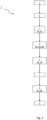
- the present invention relates to a method of controlling the supply of electricity in a two- or three-wheeled electric vehicle, generally designated by numeral 1 in the figures.
- a two- or three-wheeled electric vehicle generally designated by numeral 100 in the figures refers to an electric vehicle 100 comprising driving means 20 that are at least partially electrically powered and configured to impart motion to the vehicle 100 on a ground, and a battery-power unit 10 configured to power the driving means 20.
- driving means 20 that are at least partially electrically powered and configured to impart motion to the vehicle 100 on a ground
- battery-power unit 10 configured to power the driving means 20.
- the electric vehicle 100 may be driven/steered by a user on different types of terrain such as road and dirt patch.
- the electric vehicle 100 comprises control electronics for controlling and handling the battery power unit 10 and the driving means 20, namely one or more of their and mechanical components.
- control electronics are configured, for example, to regulate the supply of electricity and control the battery power unit 10 and the driving apparatus 20.
- the battery power unit 10 comprises a plurality of battery cells 11 and is configured to supply electric power to the electric vehicle 100
- the driving apparatus 20 comprises a plurality of mechanical and electronic components, whose combination imparts motion to the electric vehicle 100.
- the driving apparatus 20 comprises all the mechanical and electronic components required for relevant driving of the electric vehicle 100 such as, for example, a support frame 110, tires 120, an electric motor 130, transmission means 140 configured to transmit the driving force from the electric motor 130 to the tires 120, control means 150 configured to control at least the electric motor 130 and transmission means 120 and drive means 160 configured to maneuver the electric vehicle (for example, to control manual/automatic shift gearbox, brakes, dampers, etc.).
- the electric vehicle 100 may also have control and monitoring devices and/or user-wearable devices 200 associated therewith, such as smart watches for detecting vital signs of the user or a Global Positioning System (GPS).
- control and monitoring devices and/or user-wearable devices 200 associated therewith, such as smart watches for detecting vital signs of the user or a Global Positioning System (GPS).
- GPS Global Positioning System
- the method 1 of the present invention is configured to control and regulate the supply of electricity from the battery power unit 10 to the driving apparatus 20, preferably to its components as a function of an operating state of the battery power unit 10 and the driving apparatus 20. Preferably, this can be done by changing the battery control parameters that act directly on the battery power unit 10 and/or the driving apparatus 20. More preferably, the control signals that act on the relevant control electronics modify the battery control parameters to control the supply of electricity.
- the method 1 can control the supply of electricity from the battery cells 11 and the supply of electricity to the driving apparatus 20 as a function of their operating state.
- the method 1 is configured to regulate the amount of electricity to be supplied from the battery cells 11 and to supply it to the driving apparatus 20, in particular each of the components as a function of their operating states.
- this control action is carried out by changing the battery control parameters.
- the method 1 can optimize electricity management by controlling and monitoring the operating state of the electric vehicle.
- the method 1 of the present invention is also configured to control operating parameters of the battery power unit 10 and the driving apparatus 20.
- the method 1 makes it possible to further optimize the use of the battery power unit 10 as well as the driving apparatus 20.
- These operating control parameters are preferably associated with the components of the driving apparatus 20, such as the gearbox, the brake, the electric motor etc.
- the operating control parameters may also be associated with components of the battery power unit 10 such as temperature control
- the operating parameters of the electric vehicle 100 are parameters that can be monitored, whereas the battery control parameters and the operating control parameters are adjustable as a function of the operating state respectively to control the supply of electricity and to control the battery power unit 10 and the driving apparatus 20 respectively.
- these battery control and operating control parameters allow the control electronics of the battery power unit 10 and the driving apparatus 20 to be acted upon in view of changing their operating parameters and operating state.
- a change to a control parameter may have a direct or indirect effect after some time or immediately on an operating parameter of the battery power unit 10 and the driving apparatus 20.
- the method 1 comprises a step a) of acquiring, by a first set of sensors 30 associated with the battery power unit 10, a first dataset Set1 representative of operating parameters of the battery power unit 10.
- the set of sensors 30 comprises a plurality of sensors configured to acquire operating parameters of the battery power unit 10 and of each battery cell 11.
- Such plurality of sensors may be at least partially inserted inside and/or in the vicinity of the battery power unit 10, e.g. on a protective cover.
- the step a) includes acquiring, preferably in a periodic manner, data concerning the operation of the battery power unit 10 in terms of operating parameters representative of a corresponding sampling interval. This affords continuous monitoring of the battery power unit 10 and of each battery cell 11.
- the step a) can detect operating parameters for temperatures, voltages, charging currents and/or discharge currents of each battery cell 11. It should be noted that additional parameters may be detected, such as the overall temperature of the battery power unit 10 or the overall residual charge of the battery power unit 10.
- the first dataset Set1 comprises the operating parameters associated with the battery power unit 10, that can be acquired by the first set of sensors 30.
- the adjusting battery control parameters allows to modify the operating parameters of the electric vehicle 100 associated with the supply of electricity.
- the adjusting the operating control parameters affords modification of the operating parameters of the electric vehicle 100 associated with to the control of the mechanical and electrical components.
- the method 1 comprises a step b) of acquiring, by a second set of sensors 40 associated with the driving apparatus 20,a second dataset Set2 representative of operating parameters of the driving apparatus 20.
- the second set of sensors 40 comprises a plurality of sensors associated with the driving apparatus 20 preferably one or more sensors for each of its mechanical or electronic component.
- the step b) includes periodically acquiring data concerning the operation of the driving apparatus 20 in terms of operating parameters representative of a corresponding sampling interval.
- the step b) allows continuous monitoring of the operating state of the driving apparatus 20. Namely, the step b) can detect operating parameters for vehicle speed, torque delivered, motor temperatures and/or braking torque associated with the components of the driving apparatus 20.
- the second dataset Set2 comprises one or more operating parameters associated with the driving apparatus 20 and adapted to be acquired by the second set of sensors 40.
- adjustment of the operating control parameters allows modification of the operating parameters of the electric vehicle 100 associated with the control of the driving apparatus 20 as well as of the battery power unit 10.
- adjustment of battery control parameters allows modification of the operating parameters of the electric vehicle 100 associated with the supply of electricity, to be supplied to the driving apparatus 20.
- the sensors of the second set of sensors 40 may be associated with sensor devices 300 that can be associated with the electric vehicle 100 to acquire additional operating parameters of the apparatus such as: the vibration of the tires or the state of wear of the tires.
- the second dataset Set2 may also comprise additional operating parameters of the electric vehicle 100.
- the step b) includes acquiring overall operating data that can be associated with the electric vehicle 100, preferably with the driving apparatus 20.
- the sensors of the second set of sensors 40 can be associated with a user operating the electric vehicle 100 by means of corresponding user-wearable data acquisition devices 200.
- the step b) may acquire a third dataset Set3 representative of the user and comprising user-related parameters such as vital heart and/or respiratory rate parameters during use of the electric vehicle 100.
- This third dataset Set3 can then be associated with the first and second datasets Set1, Set2 to adjust the control parameters of the electric vehicle 100.
- step a) and the step b) include acquiring the first dataset Set1 and the second dataset Set2 and preferably the third dataset Set3, for each sampling time interval.
- the steps (a) and (b) can acquire datasets in temporally successive sampling intervals to continuously monitor the operating parameters of the electric vehicle 100.
- This sampling time period may range from 1 second to one or more days depending on the state of motion of the electric vehicle 100.
- the sampling interval may range from 1 second to 1 minute if the electric vehicle is moving along a path or from 1 hour to 10 hours if the electric vehicle is still relative to a reference system.
- the method allows the battery power unit to be monitored to prevent it from falling below the functionality limit of the cell even during idle periods.
- the first and second datasets, Set1, Set2 can be managed by a control unit 70 associated with the electric vehicle 100 and in signal communication with the sets of sensors 20, 30 and with the processing unit 50.
- control unit 70 is configured to control the supply of electricity from battery power unit 10 to driving apparatus 20 and to control the battery power unit 10 and the driving apparatus 20.
- the control unit 70 is configured to control the control electronics associated with the battery power unit 10 and the driving apparatus 20 preferably using battery control parameters and operating control parameters.
- the control unit 70 in signal communication with a controller 13 of the battery power unit 10 and a control unit 150 of the driving apparatus 20 is configured to control battery control parameters and operating control parameters.
- the step c) comprises a step c1) of sending the first dataset Set1 and the second dataset Set2 to the control unit 70.
- the step c) comprises a step c2) of sending, by the control unit 70, the first dataset Set1 and the second data set Set2 to the processing unit 50 in signal communication with the control unit 70.
- the method 1 includes a step d) of generating, by the processing unit 50, a system state signal Ss representative of an operating state of the electric vehicle 100.
- the system state signal Ss is a function of an operating state of the battery power unit 10 and of an operating state of the driving apparatus 20.
- the system state signal Ss can organize the set of the operating parameters acquired to define an operating state of the system at the time of sampling by the sensors.
- the state signal Ss is the aggregation, preferably organized and processed, of the acquired operating parameters that determines the operating state of the electric vehicle over the sampling interval.
- the system state signal Ss is also a function of a user state so that the control unit 70 can act on the driving apparatus 20 and/or the battery power unit 10 while also accounting for the user state.
- this system state signal Ss is representative of the operating state of the electric vehicle 100 in the sampling interval and may change to through successive sampling intervals, for example, in response to a change in the control parameters and/or a change in the use of the electric vehicle 100 by the user.
- the step d) includes generating a system state signal Ss for each sampling interval preferably designed to be stored in processing unit 50.
- the method 1 comprises a step e) of comparing, by the processing unit 50, the generated system state signal Ss with reference signals Sr associated with reference states of the Electric vehicle 100 as stored in a database 60 associated with the processing unit 50.
- the step e) includes comparing the system state signal Ss to the reference signals Sr as a function of the operating parameters to recognize the operating state of the electric vehicle 100 among the reference operating states associated with the reference signals Sr.
- this recognition allows the operating state of the system to be recognized among those available so that control signals can be later generated to optimize the use of the battery power unit 10 and/or the driving apparatus 20.
- control signals By generating control signals, as explained below, the operating state may be acted upon and changed to attain a preferred operating state.
- the step e) includes identifying a reference state for the electric vehicle 100 and associating it to the operating state of the electric vehicle 100 by comparing the operating parameters of the reference signals Sr and the system state signal Ss as a function of preset ranges of values.
- each reference signal Sr for a reference state of the electric vehicle 100 is associated with a combination of operating parameters of the battery power unit 10 and of the driving apparatus 20 having an associated preset range of values associated therewith.
- the step e) comprises the step e1) of comparing each operating parameter associated with the system state signal Ss with the operating parameters associated with the reference signals Sr via preset ranges of values.
- the step e1) includes comparing each system state signal operating parameter Ss with preset ranges of values associated with corresponding operating parameters of reference signals Sr. It should be noted that the comparison may be made also between groups of operating parameters.
- the step e) includes the step e2) of associating a reference signal with the system state signal Ss if one or more of the operating parameters associated with the system state signal Ss fall within the preset ranges of values associated with the operating parameters of the reference signals Sr.
- the step e) recognizes the operating state from the reference states.
- the temperature operating parameter of the battery power unit may be associated with a temperature range that identifies a reference state of the battery at the correct temperature and a temperature range that identifies a reference state of the critical temperature battery. If by comparison of the system state signal Sc, the battery power unit temperature falls within the correct temperature range, the method allows the correct temperature reference state to be identified as the operating state.
- the electric vehicle 100 can be acted upon by optimizing the use of the battery power unit 10 and the driving apparatus 20.
- the recognition of the operating state and/or the recognition of a sequence of operating states allows prediction by comparison of the evolution of the operating state of the electric vehicle with the reference states, whereby actions can be accordingly taken on the control parameters.
- the method 1 includes a step f) of generating a first control signal Sc1 as a function of the comparison between the generated system state signal Ss and the reference signals Sr.
- the step f) includes generating a first control signal Sc1 if an operating state has been identified from the reference states.
- each reference state has one or more actions to be taken on the electric vehicle 100 associated therewith, such as controlling the supply of electricity or controlling the battery power unit 10 and/or controlling the driving apparatus 20.
- each control signal is representative of one or more instructions to be executed on the electric vehicle 100. It should be noted that these instructions for the first control signal Sc1 are associated with changes in battery control parameters to regulate the supply of electricity.
- each first control signal is representative of a change to the battery control parameters for controlling the supply of electricity.
- This first control signal Sc1 with its modification to the battery control parameters can act on the recognized operating state and change it if needed.
- an action on the battery control parameters results in a direct or indirect change of the operating parameters that can be detected by the sensors, which might change the operating state of the electric vehicle 100 in a subsequent sampling interval. Therefore, the step f) includes generating a first control signal Sc1 to control the battery control parameters as a function of the operating state in the sampling interval.
- the first control signal Sc1 is representative of the electricity to be supplied from the battery power unit 10.
- the first control signal Sc1 can control the supply of electricity from the battery power unit 10 by controlling each battery cell 11 and/or by controlling the power supply to components of the driving apparatus 30 to be electrically powered by changing the battery parameters.
- the method can afford more efficient use of the battery power unit 10 and the driving apparatus 30 in its components.
- the first control signal Sc1 is configured to change battery control parameters such as the selection of a battery cell 11 from which the electricity will be supplied. the amount of electricity to be supplied to avoid overheating or whether a certain level of pedal assist should be activated to extend the life of the battery power unit 20.
- the method 1 comprises a step g) of regulating, by a control unit 70 in signal communication with the processing unit 50, the supply of electricity from the battery power unit 10 according to the first control signal Sc1 that has been generated.
- the step g) includes controlling by changing the battery control parameters associated with the battery power unit 10 and the driving apparatus 20 to control the supply of electricity.
- the step g) includes changing the battery control parameters to control the supply of electricity from the battery power unit 10 and to power the driving apparatus 20.
- the step g) includes acting on the control electronics of the battery power unit 10 and/or the driving apparatus 20 by the first control signal Sc1 and changing the battery control parameters.
- the step g) is conducted by means of the control unit 70 in combination with the battery power unit 10 and the driving apparatus 20.
- the step g) includes the step g1) of controlling the supply of electricity for each battery cell 11 to power the driving apparatus 20 as a function of the first control signal Sc1 by changing battery control parameters.
- the step g1) includes acting on each battery cell 11 to regulate the electricity flow from one or more battery cells 11 to the driving apparatus 11 for example to power the electric motor 130.
- the step g1) includes changing the battery control parameters as a function of the first control signal Sc1 to act on the control electronics of the battery power unit 10. More preferably, the step g1) includes switching on or off electricity supply control devices 12, e.g.
- the step g1) can modulate the electricity to be supplied from one or more battery cells 11 by changing the battery control parameters as a function of the first control signal Sc1.
- the step g) also comprises a step g2), conducted in combination with or instead of the step g1), of controlling the supply of electricity between the power battery unit 10 and the driving apparatus 20 as a function of the first control signal Sc1 by changing battery control parameters.
- the step g2) includes changing the battery control parameters as a function of the first control signal Sc1 to act on the control electronics of the driving apparatus 20 and to power or not the driving apparatus 20, namely its components.
- the step g2) includes switching on or off power devices 21 associated with the driving apparatus 20 to control the supply of electricity to the driving apparatus 20.
- the step g2) can modulate the current to power the driving apparatus 20 by changing the battery control parameters as a function of the first control signal Sc1.
- the step g2) controls the power supply to one or more components of the driving apparatus.
- the step g1) includes controlling the amount of electricity to be supplied and from which battery cells 11, while the step g2) includes checking whether the driving apparatus 20, namely its components, have to be powered.
- the step g) may change the battery control parameters to control the supply of electricity to the electric vehicle 100 as a function of the identified operating state.
- the change of the battery control parameters may correspond to a change of the operating parameters associated with the battery power unit 10 and preferably also associated with the driving apparatus 20. Such a change may accordingly lead, depending on the extent of the change in the operating parameters, to a change in operating state in subsequent sampling intervals.
- a change in the battery control parameters can allow the method to change the operating state of the electric vehicle. This will afford efficient optimization and regulation of electricity with as more efficient use of the battery power unit 10 and of the driving apparatus 20.
- the step f) includes generating, according to the comparison, a second control signal Sc2 representative of a feedback check of the battery power unit 10 and the driving apparatus 20 as a function of the operating state of the battery power unit 10 and the driving apparatus 20.
- the second control signal Sc2 is representative of changes to the operating control parameters associated with an active regulation of the components of the driving apparatus 30, such as the pedal assist level, and of the battery power unit, such as the internal temperature. More preferably, the control signal Sc2 can act on the control electronics of the battery power unit 10 and/or the driving apparatus 20 by changing the operating control parameters.
- each second control signal Sc2 is associated with changes of operating control parameters to control the battery power unit 10 and the driving apparatus 20.
- each second control signal Sc2 is representative of a change to the operating control parameters for controlling the battery power unit 10 and/or the driving apparatus 20.
- the operating control parameters can regulate one or more components of the driving apparatus 20. It should be noted that a change to the operating control parameters may lead to a consequent change to the battery control parameters to regulate the supply of electricity.
- the step g) includes checking the operating control parameters of the battery power unit 10 and the driving apparatus 20 as a function of the second control signal Sc2.
- the second control signal Sc2 can be also affected by the third user-related dataset Set3, e.g. excessive heartbeat fatigue in a given range can affect the second control signal Sc2 to increase assistance to the driving force.
- This control is conducted by means corresponding control electronics of the battery power unit 10 and the driving apparatus 20.
- the step g) can change the operating control parameters of the driving apparatus 20 and the battery power unit 10 as a function of the identified operating state. As a result, by changing the control parameters the operating state can also be changed
- a change to the operating control parameters may allow the method to change the operating state of the electric vehicle.
- the driving apparatus 20 and the battery power unit 10 can be controlled to improve vehicle performance while further optimizing the utilization of the battery power unit 10 and the driving apparatus 20
- the method identifies an operating state which corresponds to a reference state where more driving torque is required but the electric motor is in a critical condition (e.g. Excessive temperature or speed). Therefore, the method generates a first control signal that prevents the supply of electricity to avoid overheating.
- a critical condition e.g. Excessive temperature or speed.
- the method generates a first control signal to avoid an additional electricity demand from the overloaded cell and supply the electricity required from the other cells.
- steps a)-g) are repeated periodically as a function of the comparison between the system state signal Ss and the reference signals Sr.
- the method affords continuous and active control of the electric vehicle 100.
- the repetition of steps a) to g) also provides autonomous and/or semi-autonomous control of the electronics associated with the electric vehicle 100.
- the method comprises a step h) of periodically repeating the steps a) to g) as a function of the identified operating state and the generated control signals.
- the step h) includes continuously monitoring the operating state of the electric vehicle 100 as a function of the changes to the control parameters if made.
- the electric vehicle can be kept in a certain operating state between stored reference states in an autonomous and/or semi-autonomous manner.
- this determined operating state is a specific operating state suitable for the electric vehicle 100.
- the method 1 affords continuous and autonomous and/or semi-autonomous control of the battery power unit 10 and the driving apparatus 20 by managing their respective control electronics.
- the step h) also includes generating performance signals associated with the performance of the electric vehicle 100.
- These performance signals are sent to user interfaces that can be displayed by mobile devices, such as smartphones, tablets, smart watches, or fixed devices such as computers.
- the operating state of the electric vehicle 100 can also be monitored in terms of performance, such as residual charge, speed, position, etc.
- These signals can also be stored for later reference in the relevant fixed or mobile device memory areas or in the database 60.
- these performance signals may be associated with additional alarm signals if they exceed certain thresholds. These warning signals alert the user about any particular problem or state of the electric vehicle 100.
- the step h) also includes sending the performance and alarm signals to the user via the data processing unit 50 and/or the control unit 70.
- the step e) and the step f) are conducted using based on neural network- or machine learning-based algorithm resident in the processing unit 50.
- the algorithm can afford recognition of an operating state from reference states and generate corresponding control signals to be generated for active operation on the electric vehicle 100. More preferably, the algorithm can also predict the evolution of the operating state via the reference states and generate the corresponding control signals.
- the step d) of generating a system state signal Ss shall be conducted by the neural network- or machine learning-based algorithm resident in processing unit 50 so that the operating parameters will be aggregated to define a system state signal Ss representative of the operating state of the electric vehicle 100.
- the neural network-based algorithm is trained to recognize the system operating state from the reference states by associating each reference state with operating parameters of the battery power unit 10, operating parameters of the driving apparatus 20 or a combination thereof to compare them with preset ranges of values.
- the algorithm is trained by loading reference states of the electric vehicle into the database 60.
- the algorithm can also generate the control signals to change the control parameters as a function of the identified operating state by accounting for the training and the associated effect that changes of previous control features have had on the operating state.
- the method includes a step of continuously training the neural network- or machine learning-based algorithm by storing system state signals with their operating parameters and continuously updating the reference states also in relation to the ranges of values.
- This training step may also account for the effect on the operating state of the change in the control parameters as well as on the effective life of the battery power unit and driving apparatus.
- the steps d)-f) may also be conducted using comparison and recognition algorithms.
- comparison and recognition algorithms employ mathematical formulations developed for the field of application, with the aim of creating Digital Twins for reference.
- a further object of the present invention also relates to a two or three-wheeled electric vehicle 100 configured to perform the method as described above.
- the electric vehicle 20 may be driven by a user, as anticipated, who may control certain parameters to regulate driving.
- the driving apparatus 20 as mentioned above, comprises a plurality of electrical and mechanical components.
- the driving apparatus 20 comprises a support frame 110 configured to support the battery power unit 10 and the components of the driving apparatus 20.
- the support frame 110 maybe made of different materials and have different shapes.
- the driving apparatus 20 comprises tires 120 pivotally coupled to the support frame 110.
- the tires 120 are configured to provide ground contact when the electric vehicle 100 is driving, by rotating about their respective rotation axes defined by the coupling with the support frame 110, such as a pivot pin.
- the driving apparatus 20 comprises an electric motor 130 at least partially powered by the battery power unit 10 and electrically connected to the battery power unit 10.
- the electric motor 130 is entirely powered by the battery power unit 10.
- the electric motor 130 is configured to generate a driving force to drive the 120 tires.
- the driving apparatus 20 also includes transmission means 140 configured to transmit the driving force from the electric motor 130 to the tires 120. It should be noted that, according to certain embodiments, such as electric bicycles, the transmission means 140 are also configured to transmit the driving power supplied by the user to the tires 120 via the pedals.
- the transmission means 140 are also configured to transmit any driving forces from the tires to the battery power unit for charging the battery cells 11.
- the transmission means 140 may be regulated, for example, by switching the gear to control the driving force to be supplied.
- the transmission means 140 are associated with an adjustable gear switch.
- the driving apparatus 20 comprises one or more power devices 21 configured to control the supply of electricity to the driving apparatus 20 as a function of the first control signal Sc1.
- the driving apparatus 20 comprises control electronics associated with the electrical components of the driving apparatus 20 and configured to control those components as a function of the control signals that have been generated.
- this control electronics is configured to control the electricity supply control devices 21 to regulate the power supply and the electronic components.
- the equipment 20 comprises control means 150 configured to control and regulate the control parameters for the driving apparatus 10 as a function of the control signals.
- the control means 150 are associated with the electric motor 130 and the transmission means 140.
- the control means 150 are configured to control the electric motor 130 and the transmission means 140 as a function of the second control signal Sc2.
- the control means 150 are also configured to control the additional components of driving apparatus 20 such as the braking equipment, the gearbox, the lighting means as a function of the second control signal Sc2.
- the control means 150 are configured to control the supply of electricity to the driving apparatus, in particular its components as a function of the first control signal Sc1.
- the control means 150 comprise the control electronics associated with the driving apparatus 20.
- the driving apparatus 20 also includes steering equipment 160 configured to steer the electric vehicle 100 on a path of the electric vehicle 100.
- the steering means 160 comprise a handlebar or a steering wheel and corresponding steering elements associated with the 110 tires.
- the steering means 160 can adjust the direction of one or more tires 110 and hence the direction of the electric vehicle 100.
- the driving apparatus 20 also includes braking devices configured to apply a braking torque to the tires 110, lighting equipment to control the lighting of the ground and to indicate the presence of the vehicle on the ground. More preferably, the driving apparatus 20 can include electronic and mechanical components known in the art for bicycles, scooters and electric motor bikes.
- the electric vehicle 20 comprises a battery power unit 10 electrically connected to the driving apparatus 20 and configured to power the driving apparatus 20.
- the battery power unit 10 comprises a plurality of battery cells 11.
- the battery power unit 10 comprises groups of serially connected battery cells, where each group of battery cells is connected in parallel with the other groups.
- each battery cell 11 is associated with an electricity supply control device 12, such as mosfets.
- electricity supply control device 12 is configured to control the electricity supply from a corresponding battery cell 11 as a function of the first control signal Sc1.
- the battery power unit 10 may comprise additional mechanical and electronic components for the operation of the unit.
- the battery power unit 20 comprises control electronics associated with the electronic components of the battery power unit 10 and configured to control them as a function of the generated control signals.
- this control electronics is configured to control the electricity supply control devices 12 to regulate the power supply by changing the battery control parameters.
- This control electronics is also configured to control the additional components of the battery power unit 10 by changing the operating control parameters.
- the battery power unit 10 comprises a controller 13 configured to control the supply of electricity as a function of the first control signal Sc1 by adjusting the battery control parameters.
- the controller 13 is also configured to control the components of the battery power unit 20 as a function of the second control signal Sc2 by adjusting the operating control parameters.
- the battery power unit 10 comprises means for charging the battery cells 11 that can be associated with corresponding public and/or private charging stations.
- the electric vehicle 20 comprises a control unit 70 in signal communication with the driving apparatus 20 and the battery power unit 11.
- the control unit 70 is configured to regulate the supply of electricity from each battery cell 11 to the driving apparatus 20 and to control the driving apparatus 20 and preferably the battery power unit 10.
- the control unit 70 is associated with the control electronics of the battery power unit 10 and the driving apparatus 20.
- the control unit 70 is configured to change the control parameters as a function of the received control signals.
- the control unit 70 is in signal communication with control unit 150 for controlling the driving apparatus 20 and with the controller 13 for controlling the battery power unit 13.
- control unit 70 integrates the control unit 150 and the controller 13 and hence the control electronics of the battery power unit 10 and the driving apparatus 20 to directly control the driving apparatus 20 and the battery power unit 13 as a function of the control signals by changing the control parameters.
- control unit 70 is in signal communication with the electric motor via can BUS and an appropriate protocol, and in signal communication with the other components of the driving apparatus 20 via Can-BUS and/or Bluetooth and/or Ant+ and/or WiFi.
- the electric vehicle 20 comprises a first set of sensors 30 associated with the battery power unit 10 and configured to acquire a first dataset Set1 for the operating parameters of the battery power unit 10.
- the electric vehicle 1 also comprises a second set of sensors 40 associated with the driving apparatus 20 and configured to acquire a second dataset Set2, for the operating parameters of the driving apparatus 20.
- the second set of sensors 30 can also be associated with operating parameter-acquisition devices 300 that can be installed on the electric vehicle.
- the second set of sensors 40 may be also associated with user-wearable devices 200 for acquiring the third dataset Set3.
- the electric vehicle 20 comprises a processing unit 50 in signal communication with the control unit 70 and configured to receive the first and second datasets Set1, Set2 and generate a system state signal Ss as a function of the first dataset Set1 and the second dataset Set2 and preferably the third dataset Set3.
- the processing unit 50 is also configured to generate battery signals Sb, apparatus signals Sa and user signals Su to eventually generate the system state signals Ss.
- the processing unit 50 is also configured to generate a first control signal Sc1 and a second control signal Sc2 to be sent to the control unit 70 to regulate the supply of electricity, the battery power unit 10 and the driving apparatus 20.
- the processing unit comprises a plurality of modules configured to generate the different signals and compare them if needed.
- the electric vehicle 20 comprises a database 60 associated with the processing unit 50 and configured to store reference signals Sr.
- the processing unit 50 preferably with the database 60 is housed in a compartment formed on the electric vehicle 100.
- the processing unit 50 and the control unit 70 may be in wireless or wired signal communication.
- the processing unit 50 preferably in combination with the database 60, is remote from the electric vehicle 100, for example in a facility.
- the processing unit 50 and the control unit 70 may be in wireless signal communication.
- the present invention also relates to a system comprising the two- or three-wheeled electric vehicle 100 as described above, the control and monitoring devices and/or the user-worn devices 200 and sensor devices 300 associated with the vehicle.
Landscapes
- Engineering & Computer Science (AREA)
- Power Engineering (AREA)
- Transportation (AREA)
- Mechanical Engineering (AREA)
- Life Sciences & Earth Sciences (AREA)
- Sustainable Development (AREA)
- Sustainable Energy (AREA)
- Chemical & Material Sciences (AREA)
- Combustion & Propulsion (AREA)
- Electric Propulsion And Braking For Vehicles (AREA)
Priority Applications (2)
| Application Number | Priority Date | Filing Date | Title |
|---|---|---|---|
| EP22183610.9A EP4303061A1 (fr) | 2022-07-07 | 2022-07-07 | Procédé de commade de l'alimentation électrique dans un véhicule électrique à deux ou trois roues |
| PCT/EP2023/068439 WO2024008742A1 (fr) | 2022-07-07 | 2023-07-04 | Procédé de commande d'alimentation en électricité dans un véhicule électrique à deux ou trois roues |
Applications Claiming Priority (1)
| Application Number | Priority Date | Filing Date | Title |
|---|---|---|---|
| EP22183610.9A EP4303061A1 (fr) | 2022-07-07 | 2022-07-07 | Procédé de commade de l'alimentation électrique dans un véhicule électrique à deux ou trois roues |
Publications (1)
| Publication Number | Publication Date |
|---|---|
| EP4303061A1 true EP4303061A1 (fr) | 2024-01-10 |
Family
ID=83193173
Family Applications (1)
| Application Number | Title | Priority Date | Filing Date |
|---|---|---|---|
| EP22183610.9A Withdrawn EP4303061A1 (fr) | 2022-07-07 | 2022-07-07 | Procédé de commade de l'alimentation électrique dans un véhicule électrique à deux ou trois roues |
Country Status (2)
| Country | Link |
|---|---|
| EP (1) | EP4303061A1 (fr) |
| WO (1) | WO2024008742A1 (fr) |
Citations (3)
| Publication number | Priority date | Publication date | Assignee | Title |
|---|---|---|---|---|
| EP1223653A1 (fr) * | 1999-08-03 | 2002-07-17 | Tokyo R & D Co., Ltd. | Dispositif electrique avec chargeur de batterie et procede de charge et decharge correspondant |
| US20120133310A1 (en) * | 2009-07-02 | 2012-05-31 | Chong Uk Lee | Reconfigurable battery |
| US20170005371A1 (en) * | 2015-06-30 | 2017-01-05 | Faraday&Future Inc. | Vehicle energy-storage systems |
-
2022
- 2022-07-07 EP EP22183610.9A patent/EP4303061A1/fr not_active Withdrawn
-
2023
- 2023-07-04 WO PCT/EP2023/068439 patent/WO2024008742A1/fr not_active Ceased
Patent Citations (3)
| Publication number | Priority date | Publication date | Assignee | Title |
|---|---|---|---|---|
| EP1223653A1 (fr) * | 1999-08-03 | 2002-07-17 | Tokyo R & D Co., Ltd. | Dispositif electrique avec chargeur de batterie et procede de charge et decharge correspondant |
| US20120133310A1 (en) * | 2009-07-02 | 2012-05-31 | Chong Uk Lee | Reconfigurable battery |
| US20170005371A1 (en) * | 2015-06-30 | 2017-01-05 | Faraday&Future Inc. | Vehicle energy-storage systems |
Also Published As
| Publication number | Publication date |
|---|---|
| WO2024008742A1 (fr) | 2024-01-11 |
Similar Documents
| Publication | Publication Date | Title |
|---|---|---|
| CN108569365B (zh) | 自行车用控制装置及包括该控制装置的自行车用驱动装置 | |
| EP0808738B1 (fr) | Mecanisme de securite pour un vehicule electrique | |
| EP0635423B1 (fr) | Véhicule propulsé par la force musculaire | |
| US10023139B2 (en) | Bicycle control system | |
| CN1283517C (zh) | 自行车用距离显示系统及距离显示装置 | |
| CN102730134B (zh) | 自行车部件控制设备 | |
| EP2028098A2 (fr) | Système de surveillance de pression de la pédale pour bicyclette dirigée électriquement | |
| EP3168122B1 (fr) | Machine de propulsion électrique et unité de batterie | |
| EP2368745A1 (fr) | Appareil de contrôle de système pour carrosserie mobile et carrosserie mobile | |
| CN103580103A (zh) | 自行车电源系统 | |
| EP3795412A1 (fr) | Système d'alimentation | |
| CN211568218U (zh) | 自行车共享系统 | |
| EP3066002A1 (fr) | Dispositif de changement de vitesse auto-alimenté pour bicyclettes | |
| WO2021186315A1 (fr) | Système d'assistance de pédale pour bicyclette électrique et bicyclette associée | |
| EP4303061A1 (fr) | Procédé de commade de l'alimentation électrique dans un véhicule électrique à deux ou trois roues | |
| JP2021107176A (ja) | 人力駆動車用のドライブユニットおよび人力駆動車 | |
| JP2025061597A (ja) | 通信システムおよび制御装置 | |
| DE102020204201B4 (de) | Steuervorrichtung für ein Elektrofahrrad und Elektrofahrrad | |
| US20180029492A1 (en) | Dynamo for bicycles | |
| WO2023175518A1 (fr) | Procédé et système pour optimiser la gestion d'énergie et la qualité d'utilisation de véhicules assurant la mobilité de personnes et de matériaux et qui sont équipés d'une propulsion électrique ou électrifiée | |
| JP3493906B2 (ja) | 電気自転車 | |
| CN107370225A (zh) | 应用于自行车的充电控制系统和控制方法 | |
| CN115959237B (zh) | 用于人力驱动车辆的控制设备 | |
| CN119428227A (zh) | 一种重型电动工程装备智能行驶控制方法、装置 | |
| CN209833765U (zh) | 混合动力拖拉机 |
Legal Events
| Date | Code | Title | Description |
|---|---|---|---|
| PUAI | Public reference made under article 153(3) epc to a published international application that has entered the european phase |
Free format text: ORIGINAL CODE: 0009012 |
|
| STAA | Information on the status of an ep patent application or granted ep patent |
Free format text: STATUS: THE APPLICATION HAS BEEN PUBLISHED |
|
| AK | Designated contracting states |
Kind code of ref document: A1 Designated state(s): AL AT BE BG CH CY CZ DE DK EE ES FI FR GB GR HR HU IE IS IT LI LT LU LV MC MK MT NL NO PL PT RO RS SE SI SK SM TR |
|
| STAA | Information on the status of an ep patent application or granted ep patent |
Free format text: STATUS: THE APPLICATION IS DEEMED TO BE WITHDRAWN |
|
| 18D | Application deemed to be withdrawn |
Effective date: 20240711 |