EP4303828A2 - Videoanalysevorrichtung, videoanalyseverfahren und programm - Google Patents
Videoanalysevorrichtung, videoanalyseverfahren und programm Download PDFInfo
- Publication number
- EP4303828A2 EP4303828A2 EP23183584.4A EP23183584A EP4303828A2 EP 4303828 A2 EP4303828 A2 EP 4303828A2 EP 23183584 A EP23183584 A EP 23183584A EP 4303828 A2 EP4303828 A2 EP 4303828A2
- Authority
- EP
- European Patent Office
- Prior art keywords
- display
- information
- interval
- persons
- video
- Prior art date
- Legal status (The legal status is an assumption and is not a legal conclusion. Google has not performed a legal analysis and makes no representation as to the accuracy of the status listed.)
- Pending
Links
Images






Classifications
-
- G—PHYSICS
- G06—COMPUTING OR CALCULATING; COUNTING
- G06V—IMAGE OR VIDEO RECOGNITION OR UNDERSTANDING
- G06V20/00—Scenes; Scene-specific elements
- G06V20/50—Context or environment of the image
- G06V20/52—Surveillance or monitoring of activities, e.g. for recognising suspicious objects
- G06V20/53—Recognition of crowd images, e.g. recognition of crowd congestion
-
- G—PHYSICS
- G06—COMPUTING OR CALCULATING; COUNTING
- G06V—IMAGE OR VIDEO RECOGNITION OR UNDERSTANDING
- G06V20/00—Scenes; Scene-specific elements
- G06V20/40—Scenes; Scene-specific elements in video content
-
- G—PHYSICS
- G06—COMPUTING OR CALCULATING; COUNTING
- G06V—IMAGE OR VIDEO RECOGNITION OR UNDERSTANDING
- G06V40/00—Recognition of biometric, human-related or animal-related patterns in image or video data
- G06V40/10—Human or animal bodies, e.g. vehicle occupants or pedestrians; Body parts, e.g. hands
-
- G—PHYSICS
- G06—COMPUTING OR CALCULATING; COUNTING
- G06V—IMAGE OR VIDEO RECOGNITION OR UNDERSTANDING
- G06V10/00—Arrangements for image or video recognition or understanding
- G06V10/40—Extraction of image or video features
- G06V10/62—Extraction of image or video features relating to a temporal dimension, e.g. time-based feature extraction; Pattern tracking
Definitions
- the present invention relates to a video analysis apparatus, a video analysis method, and a program.
- PTL 1 discloses a congestion state notification system for promoting elimination of overcrowding.
- the congestion state notification system generates, based on an image acquired by photographing a monitoring target area, a privacy-protected image subjected to image processing in such a way that a person in the photographed image is displayed only with skeletal information.
- the congestion state notification system displays a loop line indicating an outer edge of each circular area within a predetermined distance from each person at an actual distance in the monitoring target area, in a superimposed manner in the privacy-protected image while moving the loop line according to movement of each person.
- the congestion state notification system transmits, as congestion information, the privacy-protected image in which the loop line is displayed in a superimposed manner.
- PTL 2 International Patent Publication No. WO 2021/084677 describes a technique of calculating a feature value of each of a plurality of keypoints of a human body included in an image, searching for an image including a human body having a similar pose or a human body having a similar motion, based on the calculated feature value, and classifying images with similar poses or motions together.
- NPL 1 Zhe Cao, Tomas Simon, Shih-En Wei, Yaser Sheikh, [Realtime Multi-Person 2D Pose Estimation using Part Affinity Fields];, The IEEE Conference on Computer Vision and Pattern Recognition (CVPR), 2017, PP. 7291-7299 ) describes a technique related to skeleton estimation of a person.
- PTL 1 does not describe using a result of analyzing an interval between persons included in a video, in addition to transmitting the privacy-protected image.
- PTL 2 and NPL 1 also do not disclose a technique for utilizing a result of analyzing an interval between persons included in a video.
- An example object of an embodiment of the present invention is to provide a video analysis apparatus, a video analysis method, a program and the like that solve the above-described problem of utilizing a result of analyzing an interval between persons included in a video.
- a video analysis apparatus including: an interval acquisition means for acquiring an interval between persons included in a video acquired by photographing a target region; and a display control means for causing a display means to display a time-series transition of first information relating to the number of persons with the acquired interval being equal to or less than a reference value.
- a video analysis apparatus including: an interval acquisition means for acquiring an interval between persons included in a video acquired by photographing a target region; and a display control means for causing a display means to display third information indicating, in at least three stages, a dense level of the persons in a superimposed manner on an image indicating the target region, the third information being acquired based on the acquired interval.
- a video analysis method including, by a computer: acquiring an interval between persons included in a video acquired by photographing a target region; and causing a display means to display a time-series transition of first information relating to the number of persons with the acquired interval being equal to or less than a reference value.
- a video analysis method including, by a computer: acquiring an interval between persons included in a video acquired by photographing a target region; and causing a display means to display third information indicating, in at least three stages, a dense level of the persons in a superimposed manner on an image indicating the target region, the third information being acquired based on the acquired interval.
- Fig. 1 is a diagram illustrating an outline of a video analysis apparatus 100 according to a first example embodiment.
- the video analysis apparatus 100 includes an interval acquisition unit 110 and a display control unit 113.
- the interval acquisition unit 110 acquires an interval between persons included in a video acquired by photographing a target region.
- the display control unit 113 causes a display unit to display a time-series transition of first information relating to the number of persons with the acquired interval being equal to or less than a reference value.
- the video analysis apparatus 100 it is possible to utilize a result of analyzing the interval between persons included in the video.
- Fig. 2 is a diagram illustrating an outline of a video analysis system 120 according to the first example embodiment.
- the video analysis system 120 includes a video analysis apparatus 100, at least one photographing apparatus 121_1, and an analysis apparatus 122.
- the photographing apparatus 121_1 is an apparatus that generates a video by photographing a target region.
- the analysis apparatus 122 analyzes the video and thereby detects a person included in the video, and at the same time, determines the position of the person.
- the video analysis system 120 it is possible to utilize the result of analyzing the interval between persons included in the video.
- Fig. 3 is a flowchart illustrating an example of video analysis processing according to the first example embodiment.
- the interval acquisition unit 110 acquires an interval between persons included in a video acquired by photographing a target region (step S101).
- the display control unit 113 causes a display unit to display a time-series transition of first information relating to the number of persons with the acquired interval being equal to or less than a reference value (step S104).
- the video analysis processing it is possible to utilize a result of analyzing the interval between persons included in the video.
- Fig. 4 is a diagram illustrating a detailed example of a configuration of the video analysis system 120 according to the present example embodiment.
- the video analysis system 120 includes a video analysis apparatus 100, K photographing apparatuses 121_1 to 121_K including the photographing apparatus 121_1, and an analysis apparatus 122.
- K is an integer of 1 or more.
- the video analysis apparatus 100, each of the photographing apparatuses 121_1 to 121_K, and the analysis apparatus 122 are connected to each other via a communication network N configured by wire, radio, or a combination thereof.
- the video analysis apparatus 100, each of the photographing apparatuses 121_1 to 121_K, and the analysis apparatus 122 transmit and receive information to and from each other via the communication network N.
- Each of the photographing apparatuses 121_2 to 121_K is an apparatus that generates a video acquired by photographing a target region, similarly to the above-described photographing apparatus 121_1.
- Each of the photographing apparatuses 121_1 to 121_K is, for example, a camera installed in order to photograph a predetermined photographing region in a predetermined target region.
- the target region may be a building, a facility, a municipality, a prefecture, or the like, and may be a range appropriately determined among these.
- the photographing regions of the photographing apparatuses 121_1 to 121_K may partially overlap one another, or may be regions different from one another.
- the video photographed by any one of the photographing apparatuses 121_2 to 121_K is composed of, for example, a time-series frame image (hereinafter, also simply referred to as "image") photographed at a predetermined frame rate.
- Each of the photographing apparatuses 121_2 to 121_K transmits a video acquired by photographing to the analysis apparatus 122 via the communication network N, for example, in real time.
- the analysis apparatus 122 analyzes a video acquired by photographing performed by each of the photographing apparatuses 121_1 to 121_K. As illustrated in Fig. 4 , the analysis apparatus 122 includes an analysis unit 123 and an analysis storage unit 124.
- the analysis unit 123 acquires image information 124a including images constituting the video from each of the photographing apparatuses 121_1 to 121_K, and stores the acquired image information 124a in the analysis storage unit 124.
- the analysis unit 123 analyzes an image included in each of the acquired image information 124a.
- the analysis unit 123 generates analysis information 124b indicating a result of analyzing the image, and stores the analysis information in the analysis storage unit 124.
- the analysis unit 123 transmits the image information 124a and the analysis information 124b to the video analysis apparatus 100 via the communication network N.
- the analysis unit 123 analyzes an image by using a plurality of types of engines.
- Various types of engines have a function for analyzing an image and detecting a detection target included in the image.
- the detection target includes a person.
- the detection target may include a predetermined object such as an automobile or a bag.
- the analysis unit 123 may acquire an appearance attribute of a person included in the image by analyzing the image using a plurality of types of engines.
- the appearance attribute is an attribute on the appearance of a person.
- the appearance attribute includes, for example, one or more of age group, gender, type of clothing (e.g., casual, formal, etc.) or color of clothing, type of shoes (e.g., sneakers, leather shoes, high heels, etc.) or color of shoes, hairstyle, wearing or non-wearing of a hat, wearing or non-wearing of a tie, wearing or non-wearing eyeglasses, carrying or not carrying an umbrella, and the like.
- Examples of the engine type include (1) an object detection engine, (2) a face analysis engine, (3) a humanoid analysis engine, (4) a pose analysis engine, (5) a behavior analysis engine, (6) an appearance attribute analysis engine, (7) a gradient feature analysis engine, (8) a color feature analysis engine, and (9) a flow line analysis engine.
- the analysis apparatus 122 may include at least one of an engine of the type exemplified here and an engine of another type.
- the flow line analysis engine can also acquire a flow line that straddles a plurality of images acquired by photographing different photographing regions.
- the engines of (1) to (9) can acquire reliability of the feature values acquired by the engines.
- the video analysis apparatus 100 may include an analysis unit having a function of the analysis apparatus 122.
- the analysis storage unit 124 is a storage unit for storing various kinds of information such as the image information 124a and the analysis information 124b.
- the image information 124a is information indicating each of a plurality of images.
- Fig. 5 is a diagram illustrating a configuration example of the image information 124a.
- the image information 124a associates, for example, an image ID, a photographing apparatus ID, a photographing time, and an image.
- the image ID is information (image identification information) for identifying each of the images constituting the video.
- the photographing apparatus ID is information (photographing identification information) for identifying each of the photographing apparatuses 121_1 to 121_K.
- the photographing time is information indicating a time at which an image is photographed.
- the photographing time includes, for example, a date and a time.
- an image ID and an image identified by using the image ID are associated with each other.
- a photographing apparatus ID for identifying the photographing apparatuses 121_1 to 121_K that photograph the image identified by using the image ID and a photographing time indicating a time at which the image indicated by the image ID is photographed are associated with each other.
- Fig 6 is a diagram illustrating a configuration example of the analysis information 124b.
- the analysis information 124b associates the image ID, the photographing apparatus ID, the photographing time, and an analysis result.
- the image ID, the photographing apparatus ID, and the photographing time, which are associated in the analysis information 124b, are the same as the image ID, the photographing apparatus ID, and the photographing time, which are associated in the image information 124a, respectively.
- the analysis result is information indicating a result of analyzing the image identified by using the image ID associated with the analysis result.
- an image ID for identifying an image to be analyzed in order to acquire the analysis result is associated with the analysis result.
- the analysis result associates, for example, a person ID and a position.
- the person ID is information (person identification information) for identifying a person detected from an image.
- the person ID is information for identifying a person included in the image identified by using the image ID associated with the person ID.
- the person ID is information for identifying each of the images associated to the person detected from each of a plurality of images regardless of whether or not the detection target is the same person as another.
- the person ID may be information for identifying each of persons indicated by the image associated to the person detected from each of the plurality of images.
- the person ID becomes the same person ID when the detection target is the same person as another, and becomes a different person ID when the detection target is a different person from another.
- the position is information indicating a position of a person.
- the position of the person is represented, for example, by means of a position in the image. Note that the position may be represented by using a position in the real space.
- the position indicates a position of a person identified by using the person ID associated therewith.
- the appearance attribute indicates an appearance attribute of a person.
- the appearance attribute indicates an appearance attribute of the person identified by using the person ID associated therewith.
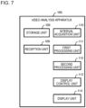
- Fig. 7 is a diagram illustrating a detailed example of a functional configuration of the video analysis apparatus 100 according to the present example embodiment.
- the video analysis apparatus 100 includes a storage unit 108, a reception unit 109, an interval acquisition unit 110, a first processing unit 111, a second processing unit 112, a display control unit 113, and a display unit 114.
- the video analysis apparatus 100 may include the analysis unit 123, and in this case, the video analysis system 120 may not include the analysis apparatus 122.
- the storage unit 108 is a storage unit for storing various kinds of information.
- the reception unit 109 receives various kinds of information such as the image information 124a and the analysis information 124b from the analysis apparatus 122 via the communication network N.
- the reception unit 109 may receive the image information 124a and the analysis information 124b from the analysis apparatus 122 in real time, or may receive the information as necessary in a case of using for processing in the video analysis apparatus 100, or the like.
- the reception unit 109 stores the received information in the storage unit 108.
- the information stored in the storage unit 108 in the present example embodiment includes the image information 124a and the analysis information 124b.
- the reception unit 109 may receive the image information 124a from the photographing apparatuses 121_1 to 121_K via the communication network N, and store the received information in the storage unit 108.
- the reception unit 109 may receive the image information 124a and the analysis information 124b from the analysis apparatus 122 via the communication network N as necessary, in a case of using for processing in the video analysis apparatus 100, or the like. In this case, the image information 124a and the analysis information 124b may not be stored in the storage unit 108.
- the analysis apparatus 122 may not hold the image information 124a and the analysis information 124b.
- the interval acquisition unit 110 acquires an interval between persons included in a video acquired by the photographing apparatuses 121_1 to 121_K photographing a target region. Specifically, the interval acquisition unit 110 determines a combination of persons included in each image constituting the video, based on the analysis information 124b. The interval acquisition unit 110 acquires an interval between persons by using the position of the analysis information 124b for each determined combination.
- the first processing unit 111 generates first information relating to the number of persons whose interval acquired by the interval acquisition unit 110 is equal to or less than a reference value.
- the reference value is a value predetermined with respect to the interval between persons, for example, 1 meter, 2 meters, or the like.
- the first processing unit 111 holds the reference value in advance, for example, based on an input from the user.
- the first information is information relating to the number of persons whose interval is equal to or less than the reference value.
- the first information may include, for example, at least one of the number of persons whose interval is equal to or less than a reference value, a ratio thereof, and the like among the persons included in each image acquired by photographing an inside of the target region.
- the first processing unit 111 acquires, for example, the total number of persons included in each image, and acquires a ratio by dividing the number of persons whose interval is equal to or less than the reference value by the total number.
- the second processing unit 112 Based on the analysis information 124b, the second processing unit 112 performs statistical processing on the appearance attribute of the person whose interval acquired by the interval acquisition unit 110 is equal to or less than the reference value. Then, the second processing unit 112 generates second information indicating a result of the statistical processing.
- the second information is information indicating a result of performing statistical processing on the appearance attribute of the person whose acquired interval is equal to or less than the reference value.
- the second information may include at least one of the number of persons according to the appearance attribute, a composition ratio, and the like for a person whose interval is equal to or less than the reference value in each image acquired by photographing the inside of the target region.
- the second processing unit 112 acquires, for example, the total number of persons included in each image, and acquires a ratio by dividing the number of persons by the appearance attribute of the person whose interval is equal to or less than the reference value by the total number.
- the second information may include at least one of an appearance attribute having the largest number of belonging persons, the number of persons who belongs to this appearance attribute, and the like, as for a person whose interval is equal to or less than a reference value in each image acquired by photographing the inside of the target region.
- the second information may include a list of appearance attributes arranged in descending order of the number of the belonging persons.
- the display control unit 113 causes the display unit 114 (for example, a display) to display various kinds of information.
- the display control unit 113 causes the display unit 114 to display a time-series transition of the first information generated by the first processing unit 111. Further, for example, the display control unit 113 causes the display unit 114 to display the second information generated by the second processing unit 112.
- the display control unit 113 may accept specification of at least one of a display target period and a display target region. When the specification of at least one of the display target period and the display target region is accepted, the display control unit 113 may cause the display unit 114 to display the time-series transition of the first information, the second information, and the like, based on the accepted specification.
- the display control unit 113 may cause the display unit 114 to display, for example, a time-series transition of the first information based on the video photographed in the display target period, the second information, and the like.
- the display control unit 113 may cause the display unit 114 to display, for example, a time-series transition of the first information based on the video associated to the display target period, the second information, and the like.
- the display target period may be specified by a date, a time zone, a combination of a date and a time zone, or the like.
- the display target area may be specified by using one or more photographing apparatus IDs.
- the display control unit 113 may set the photographing regions of the photographing apparatuses 121_1 to 121_K identified by using the specified photographing apparatus ID in the display target region.
- the display control unit 113 may cause the display unit 114 to display a video acquired by the photographing apparatuses 121_1 to 121_K photographing the target region.
- the display control unit 113 may accept specification of the display target period by accepting the specification of the image associated to each of a start time and an end time of the display target period.
- the display control unit 113 may accept specification of the display target region by accepting the specification of the region in the image constituting the video.
- Fig. 8 is a diagram illustrating an example of a physical configuration of the video analysis apparatus 100 according to the present example embodiment.
- the video analysis apparatus 100 includes a bus 1010, a processor 1020, a memory 1030, a storage device 1040, a network interface 1050, and a user interface 1060.
- the bus 1010 is a data transmission path through which the processor 1020, the memory 1030, the storage device 1040, the network interface 1050, and the user interface 1060 transmit and receive data to and from each other.
- a method of connecting the processors 1020 and the like to each other is not limited to the bus connection.
- the processor 1020 is a processor achieved by Central Processing Unit (CPU), Graphics Processing Unit (GPU), or the like.
- the memory 1030 is a main storage apparatus achieved by a Random Access Memory (RAM) or the like.
- RAM Random Access Memory
- the storage device 1040 is an auxiliary storage apparatus achieved by a Hard Disk Drive (HDD), a Solid State Drive (SSD), a memory card, a Read Only Memory (ROM), or the like.
- the storage device 1040 stores program modules for achieving the functions of the video analysis apparatus 100.
- the processor 1020 reads the program modules into the memory 1030 and executes the program modules, thereby achieving functions associated to the program modules.
- the network interface 1050 is an interface for connecting the video analysis apparatus 100 to the communication network N.
- the user interface 1060 is a touch panel, a keyboard, a mouse, or the like as an interface for the user to input information, and a liquid crystal panel, an organic Electro-Luminescence (EL) panel, or the like as an interface for presenting information to the user.
- EL organic Electro-Luminescence
- the analysis apparatus 122 may be physically configured in the same manner as the video analysis apparatus 100 (see Fig. 8 ).
- Fig. 9 is a flowchart illustrating an example of analysis processing according to the present example embodiment.
- the analysis processing is processing for analyzing the image photographed by the photographing apparatuses 121_1 to 121_K.
- the analysis processing is repeatedly executed, for example, during the operation of the photographing apparatuses 121_1 to 121_K and the analysis unit 123.
- the analysis unit 123 acquires the image information 124a from each of the photographing apparatuses 121_1 to 121_K, for example, in real time via the communication network N (step S201).
- the analysis unit 123 causes the analysis storage unit 124 to store the image information 124a acquired in step S201, and analyzes the image included in the image information 124a (step S202). Accordingly, the analysis unit 123 generates the analysis information 124b.
- the analysis unit 123 stores the analysis information 124b generated by performing the analysis in step S202 in the analysis storage unit 124, and transmits the analysis information to the video analysis apparatus 100 via the communication network N (step S203). At this time, the analysis unit 123 may transmit the image information 124a acquired in step S201 to the video analysis apparatus 100 via the communication network N.
- the reception unit 109 receives the analysis information 124b transmitted in step S203 via the communication network N (step S204). At this time, the reception unit 109 may receive the image information 124a transmitted in step S203 via the communication network N.
- the reception unit 109 stores the analysis information 124b received in step S204 in the storage unit 108 (step S205), and ends the analysis processing. At this time, the reception unit 109 may receive the image information 124a received in step S204 via the communication network N.
- video analysis processing is processing for analyzing an interval between persons included in a video by using a result of analyzing an image, and utilizing the result.
- the video analysis processing is started, for example, when the user logs in, and the display control unit 113 causes the display unit 114 to display a processing target specification screen 131.
- the processing target specification screen 131 is a screen for accepting specification of a user.
- Fig. 10 is a diagram illustrating an example of the processing target specification screen 131 according to the present example embodiment.
- the processing target specification screen 131 illustrated in Fig. 10 is a screen for specifying a processing target region and a processing target period.
- the processing target region and the processing target period are a region and a time to be processed by the interval acquisition unit 110 for acquiring an interval between persons.
- the processing target region is specified by using, for example, one or more photographing apparatus IDs. In this case, photographing regions of the photographing apparatuses 121_1 to 121_K identified by using the specified photographing apparatus ID are set in the processing target region.
- the processing target specification screen 131 includes an input field associated to each of the processing target region and the processing target period. For example, the user specifies a processing target region and a processing target period by inputting them in each input field.
- Fig. 10 illustrates an example in which three photographing apparatus IDs "photographing apparatus 1", “photographing apparatus 2", and “photographing apparatus 3" are specified by using an input field associated with the "processing target region".
- Fig. 10 illustrates an example in which a processing target period is specified with "April 1, 2022 10:00" as a start time, and "April 1, 2022 11:00" as an end time, by using an input field associated with the "processing target period”.
- the video analysis apparatus 100 starts video analysis processing illustrated in Fig. 11 .
- Fig. 11 is a flowchart illustrating a detailed example of the video analysis processing according to the present example embodiment.
- the interval acquisition unit 110 acquires an interval between persons included in a video acquired by the photographing apparatuses 121_1 to 121_K photographing a target region, for example, based on the analysis information 124b stored in the storage unit 108 (step S101).
- the interval acquisition unit 110 determines all combinations of two persons for each person included in the image. Then, the interval acquisition unit 110 acquires the interval between the persons by using the position of the analysis information 124b for each determined combination.
- Fig. 12 is a diagram illustrating an example of an interval between persons. It is assumed that the analysis information 124b includes persons with person IDs "P1", “P2", and "P3". In this case, the interval acquisition unit 110 determines a combination of the person IDs "P1” and “P2", a combination of the person IDs "P1” and “P3”, and a combination of the person IDs "P2" and “P3" as all the combinations.
- the interval acquisition unit 110 acquires an interval D1-2 for the combination of the person IDs "P1” and “P2”, based on the positions associated with these person IDs.
- the interval acquisition unit 110 acquires an interval D1-3 for the combination of the person IDs "P1” and “P3”, based on the positions associated with these person IDs.
- the interval acquisition unit 110 acquires an interval D2-3 for the combination of the person IDs "P2" and “P3", based on the positions associated with the person IDs.
- the first processing unit 111 generates first information relating to the number of persons whose interval is equal to or less than a reference value, based on the interval acquired in step S101 (step S102).
- the second processing unit 112 Based on the analysis information 124b, the second processing unit 112 performs statistical processing on an appearance attribute of the person whose interval acquired by the interval acquisition unit 110 is equal to or less than the reference value, and generates second information indicating a result of the statistical processing (step S103).
- the second processing unit 112 acquires the person ID of the person whose interval acquired in step S101 is equal to or less than the reference value and appearance information associated with the person ID.
- the second processing unit 112 performs statistical processing on the appearance attribute of the person whose interval is equal to or less than the reference value, based on the acquired person ID and appearance information.
- the display control unit 113 causes the display unit 114 to display at least one of the first information generated in step S102 and the second information generated in step S103 (step S104).
- the display control unit 113 receives a specification of a unit time for displaying a time-series transition of the first information. Upon receiving the specification of the unit time, the display control unit 113 causes the display unit 114 to display information indicating the time-series transition of the first information at time intervals according to the accepted unit time.
- Fig. 13 is a diagram illustrating an example of a number-of-persons display screen 132.
- the number-of-persons display screen 132 is an example of a screen for displaying the first information on the display unit 114.
- the number-of-persons display screen 132 illustrated in Fig. 13 is an example in which the total number of persons included in the image and the number of persons whose interval is equal to or less than the reference value are indicated by a line graph with the unit time being 10 minutes.
- the time-series transition of the first information is not limited to the line graph, and may be indicated by a bar graph or the like.
- Fig. 14 is a diagram illustrating an example of a ratio display screen 133.
- the ratio display screen 133 is another example of a screen for displaying the first information on the display unit 114.
- the ratio display screen 133 illustrated in Fig. 14 is an example in which the unit time is set to 10 minutes and the ratio of the persons whose interval is equal to or less than the reference value is indicated by a line graph.
- the time-series transition of the first information is not limited to the line graph, and may be indicated by a bar graph or the like.
- the ratio display screen 133 illustrated in Fig. 14 includes the second information of each time zone together with the ratio of the persons whose interval is equal to or less than the reference value.
- the second information illustrated in Fig. 14 is an appearance attribute having the largest number of belonging persons.
- the second information associated with a time period of, for example, 10:00 to 10:10 indicates that the appearance attribute having the largest number of belonging persons is "casual" clothing.
- the display control unit 113 may determine a mode of the screen to be displayed on the display unit 114 (for example, the number-of-persons display screen 132 or the ratio display screen 133), based on, for example, the specification of the user.
- the video analysis apparatus 100 includes the interval acquisition unit 110 and the display control unit 113.
- the interval acquisition unit 110 acquires an interval between persons included in a video acquired by photographing a target region.
- the display control unit 113 causes the display unit 114 to display a time-series transition of first information relating to the number of persons whose acquired interval is equal to or less than the reference value.
- the user can view the time-series transition of the first information relating to the number of persons whose interval is equal to or less than the reference value as for the persons included in the video. Therefore, it is possible to utilize a result of analyzing the interval between persons included in the image.
- the first information includes at least one of a ratio of persons whose interval is equal to or less than the reference value, and the number of persons whose interval is equal to or less than the reference value.
- the user can view at least one time-series transition of the ratio of persons whose interval is equal to or less than the reference value and the number of persons whose interval is equal to or less than the reference value. Therefore, it is possible to utilize the result of analyzing the interval between persons included in the image.
- the display control unit 113 further causes the display unit 114 to display second information indicating a result of performing statistical processing on an appearance attribute of the person whose acquired interval between persons is equal to or less than the reference value.
- the user can view the second information indicating the result of performing the statistical processing on the appearance attribute of the person whose interval is equal to or less than the reference value as for the persons included in the video. Therefore, it is possible to utilize the result of analyzing the interval between persons included in the image.
- the display control unit 113 when the specification of at least one of the display target period and the display target region is accepted, the display control unit 113 causes the display unit 114 to display the time-series transition of the first information, based on the accepted specification.
- the user can view the time-series transition of the first information relating to the number of persons whose interval is equal to or less than the reference value as for the persons included in the video associated to at least one of a desired display target period and a desired display target region. Therefore, it is possible to utilize the result of analyzing the interval between persons included in the image.
- the display control unit 113 when the specification of the unit time for displaying the time-series transition is accepted, the display control unit 113 causes the display unit 114 to display information indicating the time-series transition of the first information at a time interval according to the unit time.
- the user can view the time-series transition of the first information at time intervals according to the unit time. Therefore, it is possible to utilize the result of analyzing the interval between persons included in the image.
- the time-series transition of the first information or the like is displayed on the display unit 114, based on the interval between persons included in the video.
- the method of utilizing the result of analyzing the interval between persons included in the video is not limited to this.
- an example will be explained in which a dense level of persons is displayed on the display unit 114, based on the interval between the persons included in a video.
- difference points from the first example embodiment will be mainly explained, and the explanation that overlaps with the first example embodiment will be appropriately omitted.
- Fig. 15 is a diagram illustrating an outline of a video analysis apparatus 200 according to the second example embodiment.
- the video analysis apparatus 200 includes an interval acquisition unit 110 similar to that of the first example embodiment, and a display control unit 213 instead of the display control unit 113 according to the first example embodiment.
- the display control unit 213 causes the display unit to display third information indicating the dense level of the persons acquired based on the acquired interval in at least three stages in a superimposed manner on an image indicating a target region.
- the video analysis apparatus 200 it is possible to utilize a result of analyzing the interval between persons included in the video.
- Fig. 16 is a diagram illustrating an outline of a video analysis system 220 according to the second example embodiment.
- the video analysis system 220 includes a video analysis apparatus 200 instead of the video analysis apparatus 100 according to the first example embodiment, and at least one photographing apparatus 121_1 and one analysis apparatus 122 similar to the first example embodiment.
- the video analysis system 220 it is possible to utilize the result of analyzing the interval between persons included in the video.
- Fig. 17 is a flowchart illustrating an example of video analysis processing according to the second example embodiment.
- the video analysis processing according to the present example embodiment includes the same step S101 as in the first example embodiment, and a step S214 instead of the step S104 according to the first example embodiment.
- step S214 the display control unit 213 causes the display unit to display the third information indicating the dense level of the persons acquired based on the acquired interval in at least three stages in a superimposed manner on the image indicating the target region.
- the video analysis processing it is possible to utilize the result of analyzing the interval between persons included in the video.
- Fig. 18 is a diagram illustrating a detailed example of a configuration of the video analysis system 220 according to the present example embodiment.
- the video analysis system 220 includes a video analysis apparatus 200 instead of the video analysis apparatus 100 according to the first example embodiment, and photographing apparatuses 121_1 to 121_K and an analysis apparatus 122 similar to the first example embodiment.
- Fig. 19 is a diagram illustrating a detailed example of a functional configuration of the video analysis apparatus 200 according to the present example embodiment.
- the video analysis apparatus 200 includes a storage unit 108, a reception unit 109, an interval acquisition unit 110, and a display unit 114 similar to those in the first example embodiment.
- the video analysis apparatus 200 further includes a third processing unit 215 in place of the first processing unit 111 and the second processing unit 112 according to the first example embodiment, and a display control unit 213 in place of the display control unit 113 according to the first example embodiment.
- the third processing unit 215 generates third information acquired based on the interval between persons acquired by the interval acquisition unit 110.
- the third information is information indicating the dense level of the persons in at least three stages.
- the third processing unit 215 determines, for each segment acquired by dividing the target region by a predetermined method, the number of persons whose interval acquired by the interval acquisition unit 110 is equal to or less than the reference value.
- the third processing unit 215 determines a dense level of each segment, based on a predetermined criterion and the number of persons whose interval for each segment is equal to or less than the reference value.
- the third processing unit 215 generates third information, based on the determined dense level.
- the third processing unit 215 may further generate the third information, based on the analysis information 124b.
- the third processing unit 215 may store the generated third information in the storage unit 108.
- Fig. 20 is a diagram illustrating a configuration example of third information according to the present example embodiment.
- the third information is information associating image information similar to the analysis information 124b with dense information acquired based on the image information.
- the dense information is information about a dense region.
- the dense information associates a dense region ID (dense region identification information) for identifying a dense region, a person ID of a person in the dense region, an appearance attribute of a person in the dense region, and a dense level associated to the dense region.
- a dense region ID dense region identification information
- the display control unit 213 causes the display unit 114 (for example, a display) to display various kinds of information.
- the display control unit 213 causes the display unit 114 to display the third information generated by the third processing unit 215 in a superimposed manner on the image indicating the target region.
- the display control unit 213 may cause the display unit 114 to display the time-series transition of the third information, based on the accepted specification.
- the display control unit 213 may cause the display unit 114 to display information indicating the time-series transition of the third information at time intervals according to the unit time.
- the image analysis apparatus 200 may be physically configured in the same manner as the video analysis apparatus 100 according to the first example embodiment (see Fig. 8 ).
- the video analysis system 220 executes analysis processing similar to that of the first example embodiment and video analysis processing different from that of the first example embodiment.
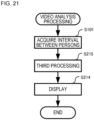
- Fig. 21 is a flowchart illustrating a detailed example of the video analysis processing according to the present example embodiment.
- the video analysis processing may be started by, for example, accepting the specification of the processing target region and the processing target period on the processing target specification screen 131 (see Fig. 11 ) similar to that in the first example embodiment, and the user pressing a start button 131a.
- the video analysis processing according to the present example embodiment includes the same step S101 as in the first example embodiment, a step S215 instead of the steps S102 to S103 according to the first example embodiment, and a step S214 instead of the step S104 according to the first example embodiment.
- step S215 the third processing unit 215 generates the third information, based on the interval between the persons acquired by the interval acquisition unit 110 and the analysis information 124b.
- the third processing unit 215 determines the dense level of each segment, based on a predetermined criterion and the number of persons whose interval for each segment is equal to or less than the reference value, and generates the third information.
- the method of generating the third information is not limited to this.
- the third processing unit 215 may determine a person whose interval between persons acquired by the interval acquisition unit 110 is equal to or less than the reference value. In this case, the third processing unit 215 may determine, based on the analysis information 124b, a person region that is a circular region centered on the position of each person whose interval is equal to or less than the reference value and whose radius is the reference value.
- the third processing unit 215 may integrate, when there are person regions at least partially overlapping each other, the overlapping person regions. As a result, the third processing unit 215 can determine a region (dense region) in which a person whose interval acquired by the interval acquisition unit 110 is equal to or less than the reference value exists.
- the third processing unit 215 determines a density of the person in the dense region (a unit is [person/square meter], for example).
- the third processing unit 215 may determine a dense level associated to the dense region, based on the predetermined reference and density.
- step S214 the display control unit 213 causes the display unit 114 to display the third information generated in step S215 together with the image on which the third information is generated.
- Fig. 22 is a diagram illustrating an example of a dense level display screen 134.
- the dense level display screen 134 is a screen for causing the display unit 114 to display the dense level together with the image.
- the dense level display screen 134 illustrated in Fig. 22 is an example of a screen in which dense regions equivalent to levels 2 and 3 are detected among the three dense levels, and the dense regions of levels 2 and 3 are displayed together with an image.
- the dense regions of different dense levels may be displayed in different manners.
- the level 2 dense regions are dotted, and the level 3 dense regions are hatched.
- the mode for displaying dense regions of different dense levels is not limited to patterns such as hatching and dots, and may include color, color density, and the like.
- Fig. 22 in the dense level display screen 134, images constituting a video may be displayed in time series. Then, the display control unit 213 may cause the display unit 114 to display the dense level display screen 134 including the third information associated to the image being displayed together with the images. As a result, it is possible to cause the display unit 114 to display the information indicating the time-series transition of the third information.
- the video analysis apparatus 200 includes the interval acquisition unit 110 and the display control unit 213.
- the display control unit 213 causes the display unit 114 to display the third information indicating the dense level of the person acquired based on the acquired interval in at least three stages, by superimposing the third information on the image indicating the target region.
- the user can view the third information indicating the dense level of the person, which is acquired based on the interval between the persons included in the video, in at least three stages, together with the image indicating the target region. Therefore, it is possible to utilize the result of analyzing the interval between persons included in the image.
- the display control unit 213 when the specification of at least one of the display target period and the display target region is accepted, the display control unit 213 causes the display unit 114 to display a time-series transition of the third information, based on the accepted designation.
- the user can view the third information acquired based on the interval between the persons included in the video associated to at least one of the desired display target period and display target region, together with the image indicating the target region. Therefore, it is possible to utilize the result of analyzing the interval between persons included in the image.
- the display control unit 213 when the specification of the unit time for displaying the time-series transition is accepted, the display control unit 213 causes the display unit 114 to display information indicating the time-series transition of the third information at a time interval according to the unit time.
- the user can view the third information at time intervals according to the unit time. Therefore, it is possible to utilize the result of analyzing the interval between persons included in the image.
- the video analysis apparatus may include the first processing unit 111 and the second processing unit 112 according to the first example embodiment, and the third processing unit 215 according to the second example embodiment.
- Fig. 23 is a diagram illustrating an example of a functional configuration of a video analysis apparatus 300 according to the present modified example.
- the video analysis apparatus 300 includes a third processing unit 215 in addition to the functional configuration of the video analysis apparatus 100 according to the first example embodiment, and a display control unit 313 in place of the display control unit 113.
- the display control unit 313 causes the display unit 114 to display at least one of the first information, the second information, and the third information in accordance with an instruction from the user.
- the user can view at least one of the first information, the second information, and the third information. Therefore, it is possible to utilize the result of analyzing the interval between persons included in the image.
Landscapes
- Engineering & Computer Science (AREA)
- Physics & Mathematics (AREA)
- General Physics & Mathematics (AREA)
- Multimedia (AREA)
- Theoretical Computer Science (AREA)
- Human Computer Interaction (AREA)
- Image Analysis (AREA)
- Closed-Circuit Television Systems (AREA)
- Testing, Inspecting, Measuring Of Stereoscopic Televisions And Televisions (AREA)
Applications Claiming Priority (1)
| Application Number | Priority Date | Filing Date | Title |
|---|---|---|---|
| JP2022108650A JP2024007265A (ja) | 2022-07-05 | 2022-07-05 | 映像分析装置、映像分析方法、及びプログラム |
Publications (2)
| Publication Number | Publication Date |
|---|---|
| EP4303828A2 true EP4303828A2 (de) | 2024-01-10 |
| EP4303828A3 EP4303828A3 (de) | 2024-03-20 |
Family
ID=87158175
Family Applications (1)
| Application Number | Title | Priority Date | Filing Date |
|---|---|---|---|
| EP23183584.4A Pending EP4303828A3 (de) | 2022-07-05 | 2023-07-05 | Videoanalysevorrichtung, videoanalyseverfahren und programm |
Country Status (3)
| Country | Link |
|---|---|
| US (1) | US20240013534A1 (de) |
| EP (1) | EP4303828A3 (de) |
| JP (1) | JP2024007265A (de) |
Citations (2)
| Publication number | Priority date | Publication date | Assignee | Title |
|---|---|---|---|---|
| JPH0464214B2 (de) | 1984-04-09 | 1992-10-14 | Ainsu Kk | |
| WO2021084677A1 (ja) | 2019-10-31 | 2021-05-06 | 日本電気株式会社 | 画像処理装置、画像処理方法及び画像処理プログラムが格納された非一時的なコンピュータ可読媒体 |
Family Cites Families (3)
| Publication number | Priority date | Publication date | Assignee | Title |
|---|---|---|---|---|
| JP2019200715A (ja) * | 2018-05-18 | 2019-11-21 | キヤノン株式会社 | 画像処理装置、画像処理方法及びプログラム |
| US20220028535A1 (en) * | 2020-07-27 | 2022-01-27 | VergeSense, Inc. | Method for mitigating disease transmission in a facility |
| JP7520663B2 (ja) * | 2020-09-24 | 2024-07-23 | エヌ・ティ・ティ・コミュニケーションズ株式会社 | 情報処理装置、情報処理方法、及びプログラム |
-
2022
- 2022-07-05 JP JP2022108650A patent/JP2024007265A/ja active Pending
-
2023
- 2023-06-28 US US18/215,540 patent/US20240013534A1/en active Pending
- 2023-07-05 EP EP23183584.4A patent/EP4303828A3/de active Pending
Patent Citations (2)
| Publication number | Priority date | Publication date | Assignee | Title |
|---|---|---|---|---|
| JPH0464214B2 (de) | 1984-04-09 | 1992-10-14 | Ainsu Kk | |
| WO2021084677A1 (ja) | 2019-10-31 | 2021-05-06 | 日本電気株式会社 | 画像処理装置、画像処理方法及び画像処理プログラムが格納された非一時的なコンピュータ可読媒体 |
Non-Patent Citations (1)
| Title |
|---|
| ZHE CAOTOMAS SIMONSHIH-EN WEIYASER SHEIKH: "Realtime Multi-Person 2D Pose Estimation using Part Affinity Fields", THE IEEE CONFERENCE ON COMPUTER VISION AND PATTERN RECOGNITION (CVPR, 2017, pages 7291 - 7299, XP055712609, DOI: 10.1109/CVPR.2017.143 |
Also Published As
| Publication number | Publication date |
|---|---|
| JP2024007265A (ja) | 2024-01-18 |
| EP4303828A3 (de) | 2024-03-20 |
| US20240013534A1 (en) | 2024-01-11 |
Similar Documents
| Publication | Publication Date | Title |
|---|---|---|
| EP3779772B1 (de) | Trajektorieverfolgungsverfahren und -einrichtung und computervorrichtung und speichermedium | |
| EP3800613A1 (de) | Bildanalysevorrichtung, personensuchsystem und personensuchverfahren | |
| WO2012013711A2 (en) | Semantic parsing of objects in video | |
| JP7318321B2 (ja) | 情報処理装置、情報処理方法、人物検索システムおよび人物検索方法 | |
| JP2008243093A (ja) | 辞書データの登録装置及び辞書データの登録方法 | |
| US11908157B2 (en) | Image processing device, image processing method, and recording medium in which program is stored | |
| KR20160120674A (ko) | 그래픽 처리 장치를 이용한 의류 추천 시스템 | |
| CN112915539A (zh) | 一种虚拟对象检测方法、装置以及可读存储介质 | |
| JP6947005B2 (ja) | 属性認識装置、属性認識方法、及び機械学習装置 | |
| CN110569918B (zh) | 一种样本分类的方法以及相关装置 | |
| CN110096983A (zh) | 一种基于神经网络的图像中施工工人安全服饰检测方法 | |
| CN114550201A (zh) | 服装规范化检测方法及装置 | |
| JP7362076B2 (ja) | 情報処理装置、情報処理方法及び情報処理プログラム | |
| WO2018155594A1 (ja) | 情報処理装置、情報処理方法、及びコンピュータ読み取り可能な記録媒体 | |
| EP4303828A2 (de) | Videoanalysevorrichtung, videoanalyseverfahren und programm | |
| HK40102789A (en) | Video analysis apparatus, video analysis method, and program | |
| JP2019128824A (ja) | 画像処理装置および画像処理方法 | |
| Dong et al. | GIAD: Generative inpainting-based anomaly detection via self-supervised learning for human monitoring | |
| CN113673351A (zh) | 一种行为检测方法、设备以及存储介质 | |
| EP4336464A1 (de) | Bildanalysevorrichtung, bildanalyseverfahren und programm | |
| US20250232614A1 (en) | Processing apparatus, processing method, and non-transitory computer-readable medium | |
| CN110633723B (zh) | 图像处理装置和方法及存储介质 | |
| EP4303829A1 (de) | Videoanalysevorrichtung, videoanalyseverfahren und programm | |
| US20220051054A1 (en) | Image processing device, image processing method, and program recording medium | |
| US20250111699A1 (en) | Image processing system, image processing method, and computer-readable medium |
Legal Events
| Date | Code | Title | Description |
|---|---|---|---|
| PUAI | Public reference made under article 153(3) epc to a published international application that has entered the european phase |
Free format text: ORIGINAL CODE: 0009012 |
|
| STAA | Information on the status of an ep patent application or granted ep patent |
Free format text: STATUS: THE APPLICATION HAS BEEN PUBLISHED |
|
| AK | Designated contracting states |
Kind code of ref document: A2 Designated state(s): AL AT BE BG CH CY CZ DE DK EE ES FI FR GB GR HR HU IE IS IT LI LT LU LV MC ME MK MT NL NO PL PT RO RS SE SI SK SM TR |
|
| PUAL | Search report despatched |
Free format text: ORIGINAL CODE: 0009013 |
|
| AK | Designated contracting states |
Kind code of ref document: A3 Designated state(s): AL AT BE BG CH CY CZ DE DK EE ES FI FR GB GR HR HU IE IS IT LI LT LU LV MC ME MK MT NL NO PL PT RO RS SE SI SK SM TR |
|
| RIC1 | Information provided on ipc code assigned before grant |
Ipc: G06V 20/52 20220101ALI20240213BHEP Ipc: G06V 20/40 20220101AFI20240213BHEP |
|
| REG | Reference to a national code |
Ref country code: HK Ref legal event code: DE Ref document number: 40102789 Country of ref document: HK |
|
| STAA | Information on the status of an ep patent application or granted ep patent |
Free format text: STATUS: REQUEST FOR EXAMINATION WAS MADE |
|
| 17P | Request for examination filed |
Effective date: 20240920 |
|
| RBV | Designated contracting states (corrected) |
Designated state(s): AL AT BE BG CH CY CZ DE DK EE ES FI FR GB GR HR HU IE IS IT LI LT LU LV MC ME MK MT NL NO PL PT RO RS SE SI SK SM TR |
|
| STAA | Information on the status of an ep patent application or granted ep patent |
Free format text: STATUS: EXAMINATION IS IN PROGRESS |
|
| 17Q | First examination report despatched |
Effective date: 20251201 |