EP4303943A2 - Récipient, système, procédé et appareil pour remplir un électrolyte d'un élément de batterie - Google Patents
Récipient, système, procédé et appareil pour remplir un électrolyte d'un élément de batterie Download PDFInfo
- Publication number
- EP4303943A2 EP4303943A2 EP23177842.4A EP23177842A EP4303943A2 EP 4303943 A2 EP4303943 A2 EP 4303943A2 EP 23177842 A EP23177842 A EP 23177842A EP 4303943 A2 EP4303943 A2 EP 4303943A2
- Authority
- EP
- European Patent Office
- Prior art keywords
- container
- electrolyte
- battery cell
- filling
- opening
- Prior art date
- Legal status (The legal status is an assumption and is not a legal conclusion. Google has not performed a legal analysis and makes no representation as to the accuracy of the status listed.)
- Granted
Links
Images


Classifications
-
- H—ELECTRICITY
- H01—ELECTRIC ELEMENTS
- H01M—PROCESSES OR MEANS, e.g. BATTERIES, FOR THE DIRECT CONVERSION OF CHEMICAL ENERGY INTO ELECTRICAL ENERGY
- H01M50/00—Constructional details or processes of manufacture of the non-active parts of electrochemical cells other than fuel cells, e.g. hybrid cells
- H01M50/60—Arrangements or processes for filling or topping-up with liquids; Arrangements or processes for draining liquids from casings
- H01M50/673—Containers for storing liquids; Delivery conduits therefor
-
- H—ELECTRICITY
- H01—ELECTRIC ELEMENTS
- H01M—PROCESSES OR MEANS, e.g. BATTERIES, FOR THE DIRECT CONVERSION OF CHEMICAL ENERGY INTO ELECTRICAL ENERGY
- H01M50/00—Constructional details or processes of manufacture of the non-active parts of electrochemical cells other than fuel cells, e.g. hybrid cells
- H01M50/60—Arrangements or processes for filling or topping-up with liquids; Arrangements or processes for draining liquids from casings
- H01M50/609—Arrangements or processes for filling with liquid, e.g. electrolytes
- H01M50/627—Filling ports
-
- Y—GENERAL TAGGING OF NEW TECHNOLOGICAL DEVELOPMENTS; GENERAL TAGGING OF CROSS-SECTIONAL TECHNOLOGIES SPANNING OVER SEVERAL SECTIONS OF THE IPC; TECHNICAL SUBJECTS COVERED BY FORMER USPC CROSS-REFERENCE ART COLLECTIONS [XRACs] AND DIGESTS
- Y02—TECHNOLOGIES OR APPLICATIONS FOR MITIGATION OR ADAPTATION AGAINST CLIMATE CHANGE
- Y02E—REDUCTION OF GREENHOUSE GAS [GHG] EMISSIONS, RELATED TO ENERGY GENERATION, TRANSMISSION OR DISTRIBUTION
- Y02E60/00—Enabling technologies; Technologies with a potential or indirect contribution to GHG emissions mitigation
- Y02E60/10—Energy storage using batteries
Definitions
- the invention relates to a container for filling a battery cell with electrolyte and a system comprising the container and a battery cell that can be filled with electrolyte.
- the invention further relates to a method and a device for filling a battery cell with electrolyte using the system.
- the basic unit of a rechargeable battery consists of a galvanic cell that includes a series of electrodes that are capable of transporting ions to each other using an electrolyte liquid bath.
- a rechargeable battery has several such cells.
- the battery cells, or more precisely their electrodes are completely wetted with electrolyte.
- long filling and wetting times of sometimes over 90 minutes per battery cell must be accepted.
- Filling battery cells on an industrial scale is therefore cost-intensive and requires a large number of machines and a large amount of space. It is therefore desirable to reduce the filling times of battery cells with electrolyte.
- One approach to reducing filling time is to use a pressure gradient so that electrolyte flows into the battery cell more quickly.
- An example is from the US 2015/0364746 A1 known. Described there is a device and a method for filling a battery cell via a piston that is open at the top.
- the piston has an outlet opening in the base plate for connecting to the opening of a battery cell.
- Using a vacuum pump the battery cell is pumped out via the piston placed on it.
- the piston is then filled with electrolyte and the pressure outside the piston, i.e. above the electrolyte level in the piston, is increased by filling the vacuum.
- the resulting pressure gradient between the non-vacuum above the electrolyte and the vacuum below the electrolyte drives the electrolyte into the battery cell.
- the filling time is reduced.
- the process can be further accelerated by not only filling the vacuum above the electrolyte level, but also by filling it Pressure above atmospheric pressure is applied, so an even greater pressure gradient is used to fill the battery cell with electrolyte.
- the invention is based on the object of providing a method and a device for filling a battery cell with electrolyte, which simplifies the filling of the battery cell and further reduces the filling time.
- the object according to the invention is achieved by a container, a system, a method and a device according to the independent patent claims. Preferred further training is the subject of the respective dependent claims.
- a first aspect relates to a container for filling a battery cell with electrolyte.
- the container includes a first inlet opening for filling electrolyte with a first valve for opening and closing the first inlet opening, a second inlet opening for filling inert gas with a second valve for opening and closing the second inlet opening, and an outlet opening for discharging electrolyte with a third valve for opening and blocking the outlet opening.
- a container is an object that has a cavity in its interior, which serves the particular purpose of separating its contents from its environment (compartmentalization).
- the first, the second and/or the third valve can preferably be actuated electromotively, electromagnetically, pneumatically or hydraulically.
- the container is preferably designed in one piece.
- the container also preferably has a round or square basic shape, particularly preferably a cylindrical, elliptical, rectangular or square basic shape.
- the basic shape is preferably determined by an outlet side of the container on which the outlet opening is arranged.
- the basic shape of the outlet side corresponds to a basic shape of a side of a battery cell, on which an opening for filling the battery cell is arranged.
- the container Due to the openings provided with valves, the container is sealed from the ambient air, in particular from a non-dry atmosphere. Through this Electrolyte contained in the container is advantageously protected without the need to provide the costly dry room atmosphere. Furthermore, the location of filling the sealed container with electrolyte is fundamentally freely selectable. Therefore, the filling process of the container with electrolyte can be decoupled from the location of the filling station and an advantageous relief of the filling stations can be achieved. During the actual filling process of the battery cell, the container can be pressurized via the second opening (by introducing inert gas) in order to force the electrolyte from the container via the outlet opening into the battery cell and to reduce the filling time.
- the container placed on a battery cell also protects the interior of the battery cell from a non-dry room atmosphere.
- the container can remain on the battery cell until the battery cell is closed in order to protect the electrolyte. This means that the closing process of the battery cell can also be decoupled from the location of the filling station and a further advantageous reduction in the load on the filling stations can be achieved.
- the filling step of the known pistons is often followed by a separate heating step, the so-called high-temperature (HT) soaking, which also has to be carried out in a dry room atmosphere.
- HT high-temperature
- the container according to the invention allows the dry room atmosphere to be dispensed with and, on the other hand, that the HT soaking and the pressurization of the container by the inert gas supply can be carried out at the same time. This not only simplifies the filling of the battery cells, but also significantly reduces the space required by the machines for filling the battery cells.
- the first valve and/or the third valve comprise a flow valve or a pressure valve (obstruction dependent on the pressure).
- Flow valves and pressure valves are valves that can selectively open or block flow in both directions. With the pressure valve, the flow is opened or blocked depending on the pressure applied or present.
- Such a valve configuration advantageously makes it possible to apply a negative pressure, preferably a vacuum, via the first inlet opening and the outlet opening in the battery cell and to use this negative pressure while filling the battery cell with electrolyte to suck the electrolyte from the container into the battery cell. This further reduces the filling time.
- By simultaneously applying pressure to the container filled with electrolyte by introducing inert gas The pressure difference between the container pressure and the battery cell pressure is further increased via the second opening in order to further reduce the filling time.
- the second valve comprises a check valve, in particular a spring-locked check valve.
- a check valve only allows flow in one direction.
- the second valve is preferably designed as a check valve in such a way that it allows a flow into the container, preferably from a pressure above 2 bar, particularly preferably above 4 bar, particularly preferably above 5 bar, but an outflow from the container through the second inlet opening prevented.
- a check valve designed in this way can advantageously be used with a filling pressure of the inert gas of up to 6 bar.
- first inlet opening and/or the second inlet opening is arranged on an inlet side and the outlet opening on an outlet side of the container, with the outlet side being opposite the inlet side.
- the container comprises a heating element for introducing thermal energy into the container and/or a heat transfer element for transferring thermal energy into the container.
- a heating element for introducing thermal energy into the container and/or a heat transfer element for transferring thermal energy into the container.
- the heat transfer element preferably comprises a large number of heating fins or fins for absorbing ambient heat.
- the ambient heat can be used during HT soaking to heat the container and achieve a convective heat transfer into the container. This allows the heating of the electrolyte in the container to be accelerated in order to achieve shorter filling and wetting times.
- the heating fins or fins are on one Arranged on the outer surface of the container. This significantly increases the surface area for convective heat transfer.
- the heating element preferably comprises a heating plate for heating the container.
- a heating plate represents a heat source.
- the heating plate is preferably arranged in direct contact with the surface of the container. This means that the heat is specifically generated in the immediate vicinity of the electrolyte to be heated, which reduces unwanted heating of surrounding objects and saves energy.
- the electrolyte can be thermally (pre-)treated independently of HT soaking.
- a system for filling a battery cell with electrolyte which comprises a container with the features described above and a battery cell that can be filled with electrolyte and has an opening, in particular an opening for filling electrolyte.
- the features of the above container described as optional can also be used analogously for the container of the system.
- the container is oriented with the outlet side towards a side of the battery cell that includes the opening.
- the outlet side of the container is preferably the side of the container that includes the outlet opening.
- the container is arranged with the outlet side on the side of the opening of the battery cell.
- the outlet opening is arranged on the outlet side in such a way that it is congruent with the opening of the battery cell.
- the outlet opening and the opening of the battery cell are preferably arranged directly one above the other when the container for filling the battery cell with electrolyte is placed on the battery cell. This has the advantage that electrolyte left out of the container flows directly into the opening of the battery cell.
- a filling neck and/or a filling hose can be provided for connecting the outlet opening to the opening of the battery cell.
- a filling neck and/or a filling hose can be provided for connecting the outlet opening to the opening of the battery cell.
- An external dimension of the outlet side is also preferably designed so that it corresponds to an external dimension of the side of the battery cell comprising the opening of a battery cell to be filled with electrolyte.
- the container preferably forms one Shadow area of the battery cell. This allows the container and battery cell to be easily stacked together. This also makes it easier to put the container on.
- the container is in a fluid connection, particularly preferably in a sealed fluid connection, with the battery cell above the outlet opening and the opening of the battery cell.
- the fluid connection can be realized, for example, using a filling nozzle or hose.
- the system comprises a fastening means for fastening the container to the battery cell.
- the fastening means is preferably a support structure for bracing the container and the battery cell.
- the support structure preferably surrounds the container and the battery cell.
- the support structure can contain recesses to save material.
- the support structure not only advantageously fastens the container and the battery cell to one another, but at the same time increases the resistance of the battery cell to a pressure gradient between the interior and exterior of the battery cell, as occurs, for example, when applying a vacuum or when introducing the inert gas into the container.
- the support structure represents a counterforce on the battery cell. Therefore, a larger pressure gradient can be used to further reduce the filling and wetting time without damaging the battery cell.
- the system can include a plurality of containers with the features described above and a plurality of battery cells that can be filled with electrolyte, each with an opening.
- the plurality of containers preferably corresponds to the plurality of battery cells, so that each battery cell can be filled with a container with electrolyte, in particular filled at the same time.
- a large number of battery cells can be filled with electrolyte without the need for a dry room atmosphere.
- the container is preferably filled with electrolyte and then placed on the battery cell in order to fill it with electrolyte.
- the container can be placed on the battery cell and then filled with electrolyte.
- the latter option offers the additional advantage that a vacuum in the battery cell can be easily created via the container, in particular via the first opening of the container. This is not possible if the container is already filled with electrolyte.
- the method includes the step of heating the container and the electrolyte.
- HT soaking of the system occurs to increase the viscosity of the electrolyte.
- the step of heating the container and the electrolyte particularly preferably takes place simultaneously with the filling of inert gas. This allows two process steps to be advantageously combined into one process step, so that the filling time of the battery cell is further reduced.
- the inert gas is preferably introduced into the container at a pressure of over 2 bar and/or up to a maximum of 10 bar, particularly preferably at a pressure of up to 6 bar.
- a step of attaching a fastening means, preferably a support structure, to the system takes place before the inert gas is introduced. This increases the resistance of the battery cell to a pressure gradient between the interior and exterior of the battery cell and a larger pressure gradient can be used to force the electrolyte into the battery cell. This further reduces the filling time of the battery cell.
- a further aspect relates to a device for filling a battery cell.
- the device comprises a system for filling a battery cell with electrolyte with the features described above, a first line connected to an electrolyte source for providing electrolyte and a second line connected to an inert gas source for providing inert gas.
- the inert gas source is preferably set up to introduce inert gas into the container at a pressure of at least 2 bar and/or up to a maximum of 10 bar, particularly preferably at a pressure of up to 6 bar.
- the first and/or second lines are preferably designed as piping.
- the piping can each consist of a tube which opens into a large number of connecting pieces, such as capillary-like end pipes or hoses.
- the individual connectors of the variety Connectors can then be used to connect to individual containers.
- the device comprises a support structure for fixing the container and the battery cell or an airtight chamber that is in fluid communication with a pressure pump.
- the support structure advantageously serves to increase the resistance of the battery cell to a pressure gradient between the interior and exterior of the battery cell.
- the pressure pump can be used to increase a chamber pressure of the airtight chamber in order to reduce the pressure gradient between the interior and exterior of the battery cell.
- the airtight chamber is dimensioned so large that the battery cell or a large number of battery cells can be filled in the chamber.
- the pressure pump is set up to set the pressure in the airtight chamber at the same level as the introduced inert gas pressure. Consequently, greater inert gas pressure can be used to force the electrolyte into the battery cell. This further reduces the filling time of the battery cell.
- the device comprises a vacuum pump.
- the vacuum pump is preferably connected via the respective first opening of the container in order to be able to create a vacuum in the battery cell.
- the vacuum can be used to create a pressure gradient.
- the device comprises a heating element or a sealed oven, which is dimensioned large enough to allow the battery cell or a plurality of battery cells to be filled. HT soaking can be performed using the heating element or oven to further reduce filling and wetting time.
- Figure 1 shows a schematic representation of a container 10 according to the invention according to one embodiment.
- the container 10 is suitable for filling a battery cell 20 with electrolyte.
- the container 10 is shown on the left in a perspective top view from above and on the right in a perspective top view from below, i.e. in an upside down position.
- the container 10 comprises on an inlet side (top) a first inlet opening 12 for filling in electrolyte and a second inlet opening 14 for filling in inert gas and on an outlet side (bottom) an outlet opening 16 for letting out electrolyte.
- the openings 12, 14, 16 each form access to an inner cavity of the container 10 that can be filled with electrolyte.
- the container 10 is preferably a cup.
- the container 10 has a rectangular basic shape.
- each of the three openings 12, 14, 16 includes a valve (not shown) for opening and blocking the corresponding opening 12, 14, 16. If all valves are blocked, the container 10 is opposite sealed in a non-dry atmosphere and electrolyte contained in the container 10, in particular electrolyte filled via the first opening 12, is advantageously protected without the need to provide a costly dry room atmosphere.
- the inner cavity can be pressurized in order to drive the electrolyte for filling a battery cell 20 from the container 10 via the outlet opening 16 into the battery cell 20. Pressurizing the container 10 via the inert gas supply creates a Pressure gradient between the inner cavity of the container 10 and an inner cavity of the battery cell 20, which serves the purpose of reducing the filling time.
- the first valve and the third valve are designed as electromagnetically actuated flow valves in order to enable the battery cell 20 to be pumped out before filling with electrolyte - as will be described later.
- the second valve is a spring-locked check valve to prevent the supplied inert gas from escaping from the container 10.
- the container 10 also has a heating element 18 for heating the container 10 in the form of a heating plate.
- the heating plate is arranged in direct contact with the surface of the container 10. This allows the container 10 to be heated directly to heat electrolyte contained therein.
- the electrolyte can be thermally pretreated before the actual filling of the battery cell 20 in order to achieve an increase in viscosity. This enables faster distribution of the electrolyte in the battery cell 20 and faster and better wetting of the battery cell 20.
- the container 10 allows the electrolyte to be heated (HT soaking) and the container 10 to be pressurized by means of an inert gas supply at the same time. This simplifies the filling of the battery cells 20 and reduces the space required by the machines for filling the battery cells 20.
- FIG 2 shows a schematic representation of a system 50 according to the invention according to one embodiment.
- the system 50 includes a variety of the in Figure 1 containers 10 shown and a plurality of battery cells 20 that can be filled with electrolyte, each with an opening 22.
- the containers 10 are each placed with the outlet side on a side of a battery cell 20 containing the opening 22.
- the basic shape of the containers 10 each corresponds to a basic shape of the battery cells 20.
- the external dimensions of the containers 10 are adapted to the basic shape of the battery cells 20 in order to enable the containers 10 to be easily placed on the battery cells 20.
- the outlet opening 16 of the respective containers 10 is located directly above the opening 22 of the respective battery cells 20.
- the outlet openings 16 are each in sealed fluid communication with the respective opening 22 in order to enable the battery cell 20 to be pumped out or filled with electrolyte.
- the containers 10 placed on the battery cells 20 seal the inner cavity of the respective battery cells 20 from a non-dry room atmosphere.
- a dry room atmosphere for filling the battery cells 20 with electrolyte is not required.
- a first method step 100 the system 50 is turned off Figure 2 provided.
- a support structure 210 is used to brace the containers 10 and the battery cells 20 (see Figure 4 ) attached to the system 50.
- the support structure 210 forms a stable frame that surrounds the system 50 and includes circumferential recesses.
- the resistance of the battery cells 20 to a pressure drop between the inner cavity and the surroundings of the battery cells 20, such as occurs, for example, when applying a vacuum or when introducing the inert gas into the container 10, is increased. Since the battery cells 20 can thereby withstand a larger pressure gradient, the filling and wetting time can be further reduced by larger pressure gradients without the battery cells 20 being damaged.
- the recesses in the support structure 210 at the level of the battery cells 20 can also be omitted if necessary in order to further increase the resistance of the battery cells 20.
- a third method step 104 the battery cells 20 are pumped out in order to obtain a negative pressure, preferably a vacuum, in the battery cell 20.
- the battery cells 20 are pumped out via a pressure pump, preferably a vacuum pump, which is connected via the first opening 10 of the container 10 and is thereby in sealed fluid connection with the battery cells 20.
- a pressure pump preferably a vacuum pump
- the third valve in the outlet opening 16 of the containers 10 can be blocked and the vacuum pump can be separated from the containers 10.
- a fourth method step 106 electrolyte is filled into the inner cavity of the containers 10 via the first opening 10 of the containers 10. After the containers 10 have been filled with electrolyte, the first valve in the first opening 10 of the containers 10 is blocked in order to seal the inner cavity of the containers 10.
- a fifth method step 108 the battery cells 20 are filled with electrolyte from the containers 10.
- the third valve of the outlet opening 16 of the container 10 is opened.
- the negative pressure (vacuum) prevailing in the battery cells 20 sucks the electrolyte into the battery cells 20.
- a sixth 110 and a seventh 112 process step take place simultaneously.
- the temperature of the electrolyte is increased by activating the heating elements 18 of the individual containers 10 and releasing heat to the containers 10.
- the heat from the containers 10 is passed on to the electrolyte located in the containers 10.
- inert gas for example nitrogen
- inert gas for example nitrogen
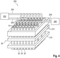
- Figure 4 shows a schematic representation of a device 200 according to the invention for filling a plurality of battery cells 20 with electrolyte according to one embodiment.
- the device 200 includes the system 50 Figure 2 , wherein the containers 10 and the battery cells 20 are held together by the previously described support structure 210.
- the device 200 also includes a first line 204 connected to an electrolyte source 202 for providing electrolyte and a second line 208 connected to an inert gas source 206 for providing inert gas.
- first 204 and the second 208 lines open into capillary-like ends, which can each be connected to the first 12 and the second 14 openings of the containers 10 in order to ensure a sealed fluid connection of the electrolyte source 202 with the first
- the first 204 and second 208 lines shown with arrows are only exemplary in nature and are not limited to the specific number of arrows shown.
Landscapes
- Chemical & Material Sciences (AREA)
- Chemical Kinetics & Catalysis (AREA)
- Electrochemistry (AREA)
- General Chemical & Material Sciences (AREA)
- Filling, Topping-Up Batteries (AREA)
Applications Claiming Priority (1)
| Application Number | Priority Date | Filing Date | Title |
|---|---|---|---|
| DE102022114793.2A DE102022114793A1 (de) | 2022-06-13 | 2022-06-13 | Behälter, System, Verfahren und Vorrichtung zum Befüllen einer Batteriezelle mit Elektrolyt |
Publications (3)
| Publication Number | Publication Date |
|---|---|
| EP4303943A2 true EP4303943A2 (fr) | 2024-01-10 |
| EP4303943A3 EP4303943A3 (fr) | 2024-06-05 |
| EP4303943B1 EP4303943B1 (fr) | 2025-08-06 |
Family
ID=86732054
Family Applications (1)
| Application Number | Title | Priority Date | Filing Date |
|---|---|---|---|
| EP23177842.4A Active EP4303943B1 (fr) | 2022-06-13 | 2023-06-07 | Récipient, système, procédé et appareil pour remplir un électrolyte d'un élément de batterie |
Country Status (4)
| Country | Link |
|---|---|
| EP (1) | EP4303943B1 (fr) |
| CN (1) | CN117239365A (fr) |
| DE (1) | DE102022114793A1 (fr) |
| ES (1) | ES3041138T3 (fr) |
Families Citing this family (1)
| Publication number | Priority date | Publication date | Assignee | Title |
|---|---|---|---|---|
| DE102025114488B3 (de) | 2025-03-03 | 2026-05-13 | GM Global Technology Operations LLC | System zur beschleunigung der elektrolytbefüllung von batteriezellen durch elektrolytdampf-vorbehandlung |
Citations (1)
| Publication number | Priority date | Publication date | Assignee | Title |
|---|---|---|---|---|
| US20150364746A1 (en) | 2013-01-30 | 2015-12-17 | CMWTEC technologie GmbH | Apparatus and method for filling a cell of a rechargeable battery with electrolyte liquid |
Family Cites Families (4)
| Publication number | Priority date | Publication date | Assignee | Title |
|---|---|---|---|---|
| US7150936B2 (en) | 2000-10-25 | 2006-12-19 | Nec Tokin Tochigi, Ltd. | Sealed battery and method for manufacturing sealed battery |
| US20060260713A1 (en) | 2005-04-22 | 2006-11-23 | Pyszczek Michael F | Method and apparatus for providing a sealed container containing a detectable gas |
| US20180301743A1 (en) | 2017-04-18 | 2018-10-18 | Tubz, Llc | Method and apparatus for manufacturing energy storage devices |
| CN110021733A (zh) * | 2019-04-12 | 2019-07-16 | 东莞天予天正新能源科技有限公司 | 一种锂离子电池注液装置及方法 |
-
2022
- 2022-06-13 DE DE102022114793.2A patent/DE102022114793A1/de active Pending
-
2023
- 2023-06-07 EP EP23177842.4A patent/EP4303943B1/fr active Active
- 2023-06-07 ES ES23177842T patent/ES3041138T3/es active Active
- 2023-06-13 CN CN202310700508.1A patent/CN117239365A/zh active Pending
Patent Citations (1)
| Publication number | Priority date | Publication date | Assignee | Title |
|---|---|---|---|---|
| US20150364746A1 (en) | 2013-01-30 | 2015-12-17 | CMWTEC technologie GmbH | Apparatus and method for filling a cell of a rechargeable battery with electrolyte liquid |
Also Published As
| Publication number | Publication date |
|---|---|
| ES3041138T3 (en) | 2025-11-07 |
| EP4303943A3 (fr) | 2024-06-05 |
| CN117239365A (zh) | 2023-12-15 |
| DE102022114793A1 (de) | 2023-12-14 |
| EP4303943B1 (fr) | 2025-08-06 |
Similar Documents
| Publication | Publication Date | Title |
|---|---|---|
| DE3138274A1 (de) | Vorrichtung zum haerten von stahlrohren | |
| DE102015005780A1 (de) | Vorrichtung zum Herstellen von dreidimensionalen Objekten | |
| EP4358286A1 (fr) | Tête de remplissage | |
| EP2876341A1 (fr) | Procédé de fonctionnement d'une soupape | |
| DE102014106631B4 (de) | Vorrichtung und Verfahren zum Herstellen von Lötverbindungen | |
| EP4303943B1 (fr) | Récipient, système, procédé et appareil pour remplir un électrolyte d'un élément de batterie | |
| DE102018108760A1 (de) | Verfahren und Vorrichtung zum Befüllen von Behältern mit karbonisiertem Füllgut und dem anschließenden Verschließen der gefüllten Behälter | |
| WO2022013830A1 (fr) | Module fonctionnel à rapprocher d'un poste de dosage positionné dans une chambre de traitement d'une enceinte de confinement, et procédé associé | |
| DE102015225148A1 (de) | Greifvorrichtung, Transportanordnung und Verfahren zum Greifen eines Gegenstandes | |
| EP3600730B1 (fr) | Dispositif, procédé et système de fabrication de pièces par impression 3d | |
| EP3663255A1 (fr) | Dispositif et procédé de remplissage d'un produit de remplissage dans un récipient à remplir dans une installation d'embouteillage | |
| WO2001066818A1 (fr) | Machine servant a revetir des corps creux | |
| EP3831500B1 (fr) | Dispositif d'arrimage, dispositif de dosage et récipient | |
| DE2510258B2 (de) | Verfahren und vorrichtung zum verschweissen eines behaelters aus kunststoff mit einem deckel | |
| DE102009054385B4 (de) | Kupplungsvorrichtung und damit ausgestattete Streckblasvorrichtung | |
| DE3928181A1 (de) | Kuehlvorrichtung fuer ein hochtemperatur-, hochdruckgefaess | |
| DE1813972A1 (de) | Verfahren und Vorrichtung zur Waermebehandlung von Produkten in luftdicht verschlossenen Behaeltern | |
| EP1525918B1 (fr) | Dispositif d'expérimenter | |
| DE102016204209A1 (de) | Einsetzvorrichtung und Verfahren zum Einsetzen eines Rondenrings in einen Außenring einer Ronde | |
| WO2008040497A1 (fr) | Dispositif de déformation sous haute pression intérieure | |
| CH626550A5 (en) | Process for producing a sintered body by hot-pressing powder of a metallic or non-metallic composition | |
| DE10027079A1 (de) | Verfahren und Vorrichtung zum Umformen eines plattenförmigen Werkstücks | |
| DE10314040B3 (de) | Verfahren und Vorrichtung zum Härten ringförmiger Werkstücke | |
| EP1767660A1 (fr) | Four sous vide à seule chambre pour trempe en hydrogène | |
| DE10211125B4 (de) | Formwerkzeug zum Tiefziehen von Behältern aus thermoplastischem Kunststoff |
Legal Events
| Date | Code | Title | Description |
|---|---|---|---|
| PUAI | Public reference made under article 153(3) epc to a published international application that has entered the european phase |
Free format text: ORIGINAL CODE: 0009012 |
|
| STAA | Information on the status of an ep patent application or granted ep patent |
Free format text: STATUS: THE APPLICATION HAS BEEN PUBLISHED |
|
| AK | Designated contracting states |
Kind code of ref document: A2 Designated state(s): AL AT BE BG CH CY CZ DE DK EE ES FI FR GB GR HR HU IE IS IT LI LT LU LV MC ME MK MT NL NO PL PT RO RS SE SI SK SM TR |
|
| PUAL | Search report despatched |
Free format text: ORIGINAL CODE: 0009013 |
|
| AK | Designated contracting states |
Kind code of ref document: A3 Designated state(s): AL AT BE BG CH CY CZ DE DK EE ES FI FR GB GR HR HU IE IS IT LI LT LU LV MC ME MK MT NL NO PL PT RO RS SE SI SK SM TR |
|
| RIC1 | Information provided on ipc code assigned before grant |
Ipc: H01M 50/673 20210101ALI20240430BHEP Ipc: H01M 50/636 20210101ALI20240430BHEP Ipc: H01M 50/627 20210101ALI20240430BHEP Ipc: H01M 50/618 20210101ALI20240430BHEP Ipc: H01M 50/609 20210101ALI20240430BHEP Ipc: H01M 10/04 20060101ALI20240430BHEP Ipc: H01M 4/00 20060101AFI20240430BHEP |
|
| STAA | Information on the status of an ep patent application or granted ep patent |
Free format text: STATUS: REQUEST FOR EXAMINATION WAS MADE |
|
| 17P | Request for examination filed |
Effective date: 20241204 |
|
| RBV | Designated contracting states (corrected) |
Designated state(s): AL AT BE BG CH CY CZ DE DK EE ES FI FR GB GR HR HU IE IS IT LI LT LU LV MC ME MK MT NL NO PL PT RO RS SE SI SK SM TR |
|
| GRAP | Despatch of communication of intention to grant a patent |
Free format text: ORIGINAL CODE: EPIDOSNIGR1 |
|
| STAA | Information on the status of an ep patent application or granted ep patent |
Free format text: STATUS: GRANT OF PATENT IS INTENDED |
|
| RIC1 | Information provided on ipc code assigned before grant |
Ipc: H01M 50/673 20210101ALI20241220BHEP Ipc: H01M 50/636 20210101ALI20241220BHEP Ipc: H01M 50/627 20210101ALI20241220BHEP Ipc: H01M 50/618 20210101ALI20241220BHEP Ipc: H01M 50/609 20210101ALI20241220BHEP Ipc: H01M 10/04 20060101ALI20241220BHEP Ipc: H01M 4/00 20060101AFI20241220BHEP |
|
| INTG | Intention to grant announced |
Effective date: 20250120 |
|
| RAP1 | Party data changed (applicant data changed or rights of an application transferred) |
Owner name: POWERCO SE |
|
| GRAS | Grant fee paid |
Free format text: ORIGINAL CODE: EPIDOSNIGR3 |
|
| P01 | Opt-out of the competence of the unified patent court (upc) registered |
Free format text: CASE NUMBER: APP_17134/2025 Effective date: 20250408 |
|
| GRAA | (expected) grant |
Free format text: ORIGINAL CODE: 0009210 |
|
| STAA | Information on the status of an ep patent application or granted ep patent |
Free format text: STATUS: THE PATENT HAS BEEN GRANTED |
|
| AK | Designated contracting states |
Kind code of ref document: B1 Designated state(s): AL AT BE BG CH CY CZ DE DK EE ES FI FR GB GR HR HU IE IS IT LI LT LU LV MC ME MK MT NL NO PL PT RO RS SE SI SK SM TR |
|
| REG | Reference to a national code |
Ref country code: GB Ref legal event code: FG4D Free format text: NOT ENGLISH |
|
| REG | Reference to a national code |
Ref country code: CH Ref legal event code: EP |
|
| REG | Reference to a national code |
Ref country code: IE Ref legal event code: FG4D Free format text: LANGUAGE OF EP DOCUMENT: GERMAN |
|
| REG | Reference to a national code |
Ref country code: DE Ref legal event code: R096 Ref document number: 502023001505 Country of ref document: DE |
|
| REG | Reference to a national code |
Ref country code: ES Ref legal event code: FG2A Ref document number: 3041138 Country of ref document: ES Kind code of ref document: T3 Effective date: 20251107 |
|
| REG | Reference to a national code |
Ref country code: NL Ref legal event code: MP Effective date: 20250806 |
|
| PG25 | Lapsed in a contracting state [announced via postgrant information from national office to epo] |
Ref country code: IS Free format text: LAPSE BECAUSE OF FAILURE TO SUBMIT A TRANSLATION OF THE DESCRIPTION OR TO PAY THE FEE WITHIN THE PRESCRIBED TIME-LIMIT Effective date: 20251206 |
|
| PG25 | Lapsed in a contracting state [announced via postgrant information from national office to epo] |
Ref country code: NO Free format text: LAPSE BECAUSE OF FAILURE TO SUBMIT A TRANSLATION OF THE DESCRIPTION OR TO PAY THE FEE WITHIN THE PRESCRIBED TIME-LIMIT Effective date: 20251106 |
|
| REG | Reference to a national code |
Ref country code: LT Ref legal event code: MG9D |
|
| PG25 | Lapsed in a contracting state [announced via postgrant information from national office to epo] |
Ref country code: PT Free format text: LAPSE BECAUSE OF FAILURE TO SUBMIT A TRANSLATION OF THE DESCRIPTION OR TO PAY THE FEE WITHIN THE PRESCRIBED TIME-LIMIT Effective date: 20251209 |
|
| PG25 | Lapsed in a contracting state [announced via postgrant information from national office to epo] |
Ref country code: FI Free format text: LAPSE BECAUSE OF FAILURE TO SUBMIT A TRANSLATION OF THE DESCRIPTION OR TO PAY THE FEE WITHIN THE PRESCRIBED TIME-LIMIT Effective date: 20250806 |
|
| PG25 | Lapsed in a contracting state [announced via postgrant information from national office to epo] |
Ref country code: HR Free format text: LAPSE BECAUSE OF FAILURE TO SUBMIT A TRANSLATION OF THE DESCRIPTION OR TO PAY THE FEE WITHIN THE PRESCRIBED TIME-LIMIT Effective date: 20250806 Ref country code: NL Free format text: LAPSE BECAUSE OF FAILURE TO SUBMIT A TRANSLATION OF THE DESCRIPTION OR TO PAY THE FEE WITHIN THE PRESCRIBED TIME-LIMIT Effective date: 20250806 |
|
| PG25 | Lapsed in a contracting state [announced via postgrant information from national office to epo] |
Ref country code: GR Free format text: LAPSE BECAUSE OF FAILURE TO SUBMIT A TRANSLATION OF THE DESCRIPTION OR TO PAY THE FEE WITHIN THE PRESCRIBED TIME-LIMIT Effective date: 20251107 |
|
| PG25 | Lapsed in a contracting state [announced via postgrant information from national office to epo] |
Ref country code: SE Free format text: LAPSE BECAUSE OF FAILURE TO SUBMIT A TRANSLATION OF THE DESCRIPTION OR TO PAY THE FEE WITHIN THE PRESCRIBED TIME-LIMIT Effective date: 20250806 |
|
| PG25 | Lapsed in a contracting state [announced via postgrant information from national office to epo] |
Ref country code: LV Free format text: LAPSE BECAUSE OF FAILURE TO SUBMIT A TRANSLATION OF THE DESCRIPTION OR TO PAY THE FEE WITHIN THE PRESCRIBED TIME-LIMIT Effective date: 20250806 |
|
| PG25 | Lapsed in a contracting state [announced via postgrant information from national office to epo] |
Ref country code: BG Free format text: LAPSE BECAUSE OF FAILURE TO SUBMIT A TRANSLATION OF THE DESCRIPTION OR TO PAY THE FEE WITHIN THE PRESCRIBED TIME-LIMIT Effective date: 20250806 Ref country code: PL Free format text: LAPSE BECAUSE OF FAILURE TO SUBMIT A TRANSLATION OF THE DESCRIPTION OR TO PAY THE FEE WITHIN THE PRESCRIBED TIME-LIMIT Effective date: 20250806 |
|
| PG25 | Lapsed in a contracting state [announced via postgrant information from national office to epo] |
Ref country code: RS Free format text: LAPSE BECAUSE OF FAILURE TO SUBMIT A TRANSLATION OF THE DESCRIPTION OR TO PAY THE FEE WITHIN THE PRESCRIBED TIME-LIMIT Effective date: 20251106 |
|
| PG25 | Lapsed in a contracting state [announced via postgrant information from national office to epo] |
Ref country code: SM Free format text: LAPSE BECAUSE OF FAILURE TO SUBMIT A TRANSLATION OF THE DESCRIPTION OR TO PAY THE FEE WITHIN THE PRESCRIBED TIME-LIMIT Effective date: 20250806 |
|
| PG25 | Lapsed in a contracting state [announced via postgrant information from national office to epo] |
Ref country code: DK Free format text: LAPSE BECAUSE OF FAILURE TO SUBMIT A TRANSLATION OF THE DESCRIPTION OR TO PAY THE FEE WITHIN THE PRESCRIBED TIME-LIMIT Effective date: 20250806 |
|
| PG25 | Lapsed in a contracting state [announced via postgrant information from national office to epo] |
Ref country code: IT Free format text: LAPSE BECAUSE OF FAILURE TO SUBMIT A TRANSLATION OF THE DESCRIPTION OR TO PAY THE FEE WITHIN THE PRESCRIBED TIME-LIMIT Effective date: 20250806 |
|
| PG25 | Lapsed in a contracting state [announced via postgrant information from national office to epo] |
Ref country code: CZ Free format text: LAPSE BECAUSE OF FAILURE TO SUBMIT A TRANSLATION OF THE DESCRIPTION OR TO PAY THE FEE WITHIN THE PRESCRIBED TIME-LIMIT Effective date: 20250806 |
|
| PG25 | Lapsed in a contracting state [announced via postgrant information from national office to epo] |
Ref country code: EE Free format text: LAPSE BECAUSE OF FAILURE TO SUBMIT A TRANSLATION OF THE DESCRIPTION OR TO PAY THE FEE WITHIN THE PRESCRIBED TIME-LIMIT Effective date: 20250806 Ref country code: SK Free format text: LAPSE BECAUSE OF FAILURE TO SUBMIT A TRANSLATION OF THE DESCRIPTION OR TO PAY THE FEE WITHIN THE PRESCRIBED TIME-LIMIT Effective date: 20250806 |
|
| REG | Reference to a national code |
Ref country code: DE Ref legal event code: R097 Ref document number: 502023001505 Country of ref document: DE |
|
| PLBE | No opposition filed within time limit |
Free format text: ORIGINAL CODE: 0009261 |
|
| STAA | Information on the status of an ep patent application or granted ep patent |
Free format text: STATUS: NO OPPOSITION FILED WITHIN TIME LIMIT |
|
| REG | Reference to a national code |
Ref country code: CH Ref legal event code: L10 Free format text: ST27 STATUS EVENT CODE: U-0-0-L10-L00 (AS PROVIDED BY THE NATIONAL OFFICE) Effective date: 20260617 |
|
| PG25 | Lapsed in a contracting state [announced via postgrant information from national office to epo] |
Ref country code: LT Free format text: LAPSE BECAUSE OF FAILURE TO SUBMIT A TRANSLATION OF THE DESCRIPTION OR TO PAY THE FEE WITHIN THE PRESCRIBED TIME-LIMIT Effective date: 20250806 |
|
| PGFP | Annual fee paid to national office [announced via postgrant information from national office to epo] |
Ref country code: DE Payment date: 20260630 Year of fee payment: 4 |
|
| 26N | No opposition filed |
Effective date: 20260507 |
|
| PGFP | Annual fee paid to national office [announced via postgrant information from national office to epo] |
Ref country code: AT Payment date: 20260714 Year of fee payment: 4 |
|
| PGFP | Annual fee paid to national office [announced via postgrant information from national office to epo] |
Ref country code: FR Payment date: 20260622 Year of fee payment: 4 |