EP4304802B1 - Dispositif et procédé de découpe laser d'une pièce et production de pièces - Google Patents
Dispositif et procédé de découpe laser d'une pièce et production de pièces Download PDFInfo
- Publication number
- EP4304802B1 EP4304802B1 EP22711546.6A EP22711546A EP4304802B1 EP 4304802 B1 EP4304802 B1 EP 4304802B1 EP 22711546 A EP22711546 A EP 22711546A EP 4304802 B1 EP4304802 B1 EP 4304802B1
- Authority
- EP
- European Patent Office
- Prior art keywords
- laser beam
- movement
- cutting head
- unit
- parameter
- Prior art date
- Legal status (The legal status is an assumption and is not a legal conclusion. Google has not performed a legal analysis and makes no representation as to the accuracy of the status listed.)
- Active
Links
Images





Classifications
-
- B—PERFORMING OPERATIONS; TRANSPORTING
- B23—MACHINE TOOLS; METAL-WORKING NOT OTHERWISE PROVIDED FOR
- B23K—SOLDERING OR UNSOLDERING; WELDING; CLADDING OR PLATING BY SOLDERING OR WELDING; CUTTING BY APPLYING HEAT LOCALLY, e.g. FLAME CUTTING; WORKING BY LASER BEAM
- B23K26/00—Working by laser beam, e.g. welding, cutting or boring
- B23K26/36—Removing material
- B23K26/38—Removing material by boring or cutting
-
- B—PERFORMING OPERATIONS; TRANSPORTING
- B23—MACHINE TOOLS; METAL-WORKING NOT OTHERWISE PROVIDED FOR
- B23K—SOLDERING OR UNSOLDERING; WELDING; CLADDING OR PLATING BY SOLDERING OR WELDING; CUTTING BY APPLYING HEAT LOCALLY, e.g. FLAME CUTTING; WORKING BY LASER BEAM
- B23K26/00—Working by laser beam, e.g. welding, cutting or boring
- B23K26/02—Positioning or observing the workpiece, e.g. with respect to the point of impact; Aligning, aiming or focusing the laser beam
- B23K26/03—Observing, e.g. monitoring, the workpiece
-
- B—PERFORMING OPERATIONS; TRANSPORTING
- B23—MACHINE TOOLS; METAL-WORKING NOT OTHERWISE PROVIDED FOR
- B23K—SOLDERING OR UNSOLDERING; WELDING; CLADDING OR PLATING BY SOLDERING OR WELDING; CUTTING BY APPLYING HEAT LOCALLY, e.g. FLAME CUTTING; WORKING BY LASER BEAM
- B23K26/00—Working by laser beam, e.g. welding, cutting or boring
- B23K26/02—Positioning or observing the workpiece, e.g. with respect to the point of impact; Aligning, aiming or focusing the laser beam
- B23K26/06—Shaping the laser beam, e.g. by masks or multi-focusing
- B23K26/064—Shaping the laser beam, e.g. by masks or multi-focusing by means of optical elements, e.g. lenses, mirrors or prisms
- B23K26/0643—Shaping the laser beam, e.g. by masks or multi-focusing by means of optical elements, e.g. lenses, mirrors or prisms comprising mirrors
-
- B—PERFORMING OPERATIONS; TRANSPORTING
- B23—MACHINE TOOLS; METAL-WORKING NOT OTHERWISE PROVIDED FOR
- B23K—SOLDERING OR UNSOLDERING; WELDING; CLADDING OR PLATING BY SOLDERING OR WELDING; CUTTING BY APPLYING HEAT LOCALLY, e.g. FLAME CUTTING; WORKING BY LASER BEAM
- B23K26/00—Working by laser beam, e.g. welding, cutting or boring
- B23K26/02—Positioning or observing the workpiece, e.g. with respect to the point of impact; Aligning, aiming or focusing the laser beam
- B23K26/06—Shaping the laser beam, e.g. by masks or multi-focusing
- B23K26/064—Shaping the laser beam, e.g. by masks or multi-focusing by means of optical elements, e.g. lenses, mirrors or prisms
- B23K26/0648—Shaping the laser beam, e.g. by masks or multi-focusing by means of optical elements, e.g. lenses, mirrors or prisms comprising lenses
-
- B—PERFORMING OPERATIONS; TRANSPORTING
- B23—MACHINE TOOLS; METAL-WORKING NOT OTHERWISE PROVIDED FOR
- B23K—SOLDERING OR UNSOLDERING; WELDING; CLADDING OR PLATING BY SOLDERING OR WELDING; CUTTING BY APPLYING HEAT LOCALLY, e.g. FLAME CUTTING; WORKING BY LASER BEAM
- B23K26/00—Working by laser beam, e.g. welding, cutting or boring
- B23K26/08—Devices involving relative movement between laser beam and workpiece
- B23K26/082—Scanning systems, i.e. devices involving movement of the laser beam relative to the laser head
- B23K26/0821—Scanning systems, i.e. devices involving movement of the laser beam relative to the laser head using multifaceted mirrors, e.g. polygonal mirror
-
- B—PERFORMING OPERATIONS; TRANSPORTING
- B23—MACHINE TOOLS; METAL-WORKING NOT OTHERWISE PROVIDED FOR
- B23K—SOLDERING OR UNSOLDERING; WELDING; CLADDING OR PLATING BY SOLDERING OR WELDING; CUTTING BY APPLYING HEAT LOCALLY, e.g. FLAME CUTTING; WORKING BY LASER BEAM
- B23K26/00—Working by laser beam, e.g. welding, cutting or boring
- B23K26/08—Devices involving relative movement between laser beam and workpiece
- B23K26/0869—Devices involving movement of the laser head in at least one axial direction
- B23K26/0876—Devices involving movement of the laser head in at least one axial direction in at least two axial directions
-
- B—PERFORMING OPERATIONS; TRANSPORTING
- B23—MACHINE TOOLS; METAL-WORKING NOT OTHERWISE PROVIDED FOR
- B23K—SOLDERING OR UNSOLDERING; WELDING; CLADDING OR PLATING BY SOLDERING OR WELDING; CUTTING BY APPLYING HEAT LOCALLY, e.g. FLAME CUTTING; WORKING BY LASER BEAM
- B23K26/00—Working by laser beam, e.g. welding, cutting or boring
- B23K26/08—Devices involving relative movement between laser beam and workpiece
- B23K26/0869—Devices involving movement of the laser head in at least one axial direction
- B23K26/0876—Devices involving movement of the laser head in at least one axial direction in at least two axial directions
- B23K26/0884—Devices involving movement of the laser head in at least one axial direction in at least two axial directions in at least three axial directions, e.g. manipulators, robots
-
- B—PERFORMING OPERATIONS; TRANSPORTING
- B23—MACHINE TOOLS; METAL-WORKING NOT OTHERWISE PROVIDED FOR
- B23K—SOLDERING OR UNSOLDERING; WELDING; CLADDING OR PLATING BY SOLDERING OR WELDING; CUTTING BY APPLYING HEAT LOCALLY, e.g. FLAME CUTTING; WORKING BY LASER BEAM
- B23K26/00—Working by laser beam, e.g. welding, cutting or boring
- B23K26/08—Devices involving relative movement between laser beam and workpiece
- B23K26/082—Scanning systems, i.e. devices involving movement of the laser beam relative to the laser head
-
- B—PERFORMING OPERATIONS; TRANSPORTING
- B23—MACHINE TOOLS; METAL-WORKING NOT OTHERWISE PROVIDED FOR
- B23K—SOLDERING OR UNSOLDERING; WELDING; CLADDING OR PLATING BY SOLDERING OR WELDING; CUTTING BY APPLYING HEAT LOCALLY, e.g. FLAME CUTTING; WORKING BY LASER BEAM
- B23K31/00—Processes relevant to this subclass, specially adapted for particular articles or purposes, but not covered by any single one of main groups B23K1/00 - B23K28/00
- B23K31/12—Processes relevant to this subclass, specially adapted for particular articles or purposes, but not covered by any single one of main groups B23K1/00 - B23K28/00 relating to investigating the properties, e.g. the weldability, of materials
-
- B—PERFORMING OPERATIONS; TRANSPORTING
- B23—MACHINE TOOLS; METAL-WORKING NOT OTHERWISE PROVIDED FOR
- B23K—SOLDERING OR UNSOLDERING; WELDING; CLADDING OR PLATING BY SOLDERING OR WELDING; CUTTING BY APPLYING HEAT LOCALLY, e.g. FLAME CUTTING; WORKING BY LASER BEAM
- B23K31/00—Processes relevant to this subclass, specially adapted for particular articles or purposes, but not covered by any single one of main groups B23K1/00 - B23K28/00
- B23K31/12—Processes relevant to this subclass, specially adapted for particular articles or purposes, but not covered by any single one of main groups B23K1/00 - B23K28/00 relating to investigating the properties, e.g. the weldability, of materials
- B23K31/125—Weld quality monitoring
Definitions
- the spot size of the focused laser beam is adapted to the metal sheet thickness and the material of the sheet.
- Approaches that go a step further in adapting the laser beam tool to the machining process are those in which the intensity distribution and/or the beam quality of the laser beam, for example the beam parameter product (BPP), can also be adapted to the laser application.
- BPP beam parameter product
- High frequency beam oscillation is one of the technologies of dynamic beam shaping (DBS).
- DBS dynamic beam shaping
- the laser beam or in the case of a focussed laser beam its focal point, is moved at frequencies of, for example, 100 Hz to 10 kHz, in particular perpendicular to the direction of propagation of the laser beam.
- a DBS system integrated in a laser machining head.
- the dynamic properties of a DBS system such as speed and acceleration, are significant, for example a factor of 1000 or more higher than those of the mechanical axes of the laser machining device.
- the working range of the DBS system is small, for example a few hundred micrometres to a few millimetres.
- Better cutting results can be achieved using a laser tool adapted to the DBS system, see e.g., Wetzig et al.: Fast Beam Oscillations Improve Laser Cutting of Thick Materials, State of the Art and Outlook, PhotonicsViews, 3/2020 ; Goppold et al.: Chancen undducten der dynamischen Strahlformung, Deutscher Schneidkongress, 2018 ; Goppold, et al.: Dynamic Beam Shaping Improves Laser Cutting of Thick Steel Plates, Industrial Photonics, 2017 ; Goppold, et al.: Laserschmelzclose mit dynamischer Strahlformung, Fraunhofer IWSpreferablybericht, 2015 ; Mahrle et al.: theoretical aspects of fibre laser cutting, Journal of Physics D
- the working range of the mechanical axes of a laser cutting device in X and Y directions is large, the dynamics of the mechanical axes are small, for example 1m/s, respectively 10m/s ⁇ 2. Due to the dynamic limits of the mechanical axes, the speed of the cutting head movement is typically reduced when laser cutting in corners and small radii of the workpiece parts to be produced. Dynamic limits of the mechanical axes are often deliberately chosen to be smaller than physically possible in order to reduce errors in the contours, what are termed contour errors, of the workpiece parts to be cut. However, this requires significantly more time for the laser cutting process and significantly reduces the productivity of the laser cutting device.
- a rounding of the geometry to be cut or of the trajectory of the cutting head can be applied, especially at corners and small radii of the workpiece parts.
- the rounding can result in undesirable contour errors as a deviation from the target contour of the workpiece.
- US 2020/398373 A1 which forms the closest prior art, discloses an optical device for shaping an electromagnetic wave beam, having an optical element positioned within beam propagation direction, and an exciter means functionally connected to the optical element for inducing an oscillation of the focal point in at least one of an x direction and any direction of a plane perpendicular to the beam propagation direction along a focal point oscillation path.
- EP 3747588 A1 discloses a processing device for laser processing of a workpiece in a processing zone, with at least one stationary laser beam guidance device with at least one movable surface, the at least one movable surface being adjustable in such a way that it modifies the focal length of the optical system and/or the beam parameter product of the time-integrated processing laser beam in at least one operating mode.
- DE 102018220336 A1 describes a device for beam shaping.
- a second optical deflection element is designed to shift a point of impact of the laser beam on a workpiece surface
- a first optical deflection element is designed to position a focal plane of the laser beam relative to the workpiece surface by a translational movement and/or to change an intensity distribution within a beam cross section of the laser beam.
- DE 102019120830 A1 discloses a guide device for guiding a laser beam, comprising a deflection unit for guiding a laser focus of the laser beam along a trajectory, said deflection unit comprising at least one movable optical element arranged in the beam path of the laser beam and serving for deflecting the laser beam, and comprising a control unit for controlling the at least one movable optical element, said control unit comprising a trajectory planning program for planning the trajectory of the laser focus.
- a guide device for guiding a laser beam comprising a deflection unit for guiding a laser focus of the laser beam along a trajectory, said deflection unit comprising at least one movable optical element arranged in the beam path of the laser beam and serving for deflecting the laser beam, and comprising a control unit for controlling the at least one movable optical element, said control unit comprising a trajectory planning program for planning the trajectory of the laser focus.
- a laser beam is deflected two-dimensionally by means of at least one reflective, pivotable element and is directed onto the surface of the workpiece together with a cutting gas using focusing optics through a cutting nozzle.
- a two-axis relative movement between the workpiece and the laser beam is carried out with elements accommodated in a cutting head.
- US 2020/246920 A1 discloses a laser cutting device including a control unit that controls operations of laser machining robot and laser oscillator.
- One embodiment of the invention relates to a device for laser cutting a workpiece, preferably a workpiece made of or containing at least one metal, and producing workpiece parts, comprising a cutting head.
- the cutting head has an interface for a laser source for generating a machining laser beam with a power of at least 200 W, preferably at least 1 kW, more preferably 1 kW to 40 kW, an exit aperture for the machining laser beam, and laser beam optics between the interface and the exit aperture.
- the laser beam optics have at least one dynamic laser beam movement unit for producing a high frequency beam-shaping movement of the machining laser beam at least perpendicular to its direction of propagation.
- the device for laser cutting is provided with a cutting head movement unit for performing a movement of the machining laser beam over the workpiece via the cutting head; and a control unit for controlling the cutting head movement unit and the laser beam movement unit.
- the control unit has:
- the optimisation module is configured for optimising the movement trajectory by redundantly partitioning the movement trajectory of the machining laser beam between the cutting head movement unit and the laser beam movement unit.
- the optimisation module can be configured for optimising the movement trajectory of the machining laser beam in at least one workpiece plane by redundantly partitioning the movement trajectory of the machining laser beam between the cutting head movement unit and the laser beam movement unit.
- the movement trajectory of the machining laser beam in at least one workpiece plane can be reorganized by reallocating components of the movement trajectory of the laser beam to the slow mechanical axes of the cutting head movement unit and/or by reallocating components of the movement trajectory of the laser beam to the at least one fast dynamic laser beam movement unit, based on the at least one predetermined parameter selected from the movement parameter of the cutting head movement unit, the movement parameter of the laser beam movement unit and the parameter of a deviation of a cut contour from the predetermined contour.
- the movement trajectory of the machining laser beam can be sophisticatedly, flexibly and/or continuously or discontinuously changed and/or varied along its length at least at regions thereof, in which deviations of the actual cut contour from the target contour occur, and thus optimised.
- the movement trajectory of the machining laser beam is decisively improved as compared to a simple superposition of the movement of the machining laser beam over the workpiece via the cutting head and of the high frequency beam-shaping movement of the machining laser beam at least perpendicular to its direction of propagation.
- the optimisation module can be configured for adjusting, e.g. increasing or reducing, and/or for optimising at least one parameter selected from the movement parameter of the cutting head movement unit, the movement parameter of the laser beam movement unit and the parameter of a deviation of a cut contour from the predetermined contour and/or for thus predetermining the respective parameter.
- at least one of the respective other at least one parameters can be optimised and/or thus predetermined.
- at least one rounding tolerance of the cutting head movement unit and/or at least one dynamic limit of the cutting head movement unit can be adapted, e.g. increased.
- a movement parameter of the dynamic laser beam movement unit can be adapted and/or optimised, in order to optimise the eventual movement trajectory of the machining laser beam.
- undesired deviations of the movement trajectory from an ideal movement trajectory corresponding to the predetermined contour of the workpiece parts to be produced, such as a cutting plan can be compensated for and/or avoided in this manner.
- path deviations of the cutting head movement unit induced by the dynamics of the cutting head movement unit and/or contour errors and/or surface defects of the workpiece parts to be produced, such as scoring, surface roughness or adhering burr can be reduced or avoided.
- the cutting process can be shortened in time, as the optimised movement trajectory means that the speed of the cutting head need not be reduced in corners and small radii of the workpiece parts to be produced.
- the parameter of a deviation of a cut contour from the predetermined contour can be at least one of an estimated deviation, a parameter resulting from a measured deviation, a rounding of the cut contour at an angle of the predetermined contour, a rounding of the cut contour at a radius of the predetermined contour, an estimated surface defect of a cut edge, and a parameter resulting from a measured surface defect of a cut edge.
- the movement trajectory of the machining laser beam can be adjusted by the optimisation module and thus be optimised. This can be realised by suitably partitioning the movement trajectory of the machining laser beam between the cutting head movement unit and the laser beam movement unit. In this way, an optimised movement of the cutting head movement unit, in particular of its mechanical axes, can be achieved. Furthermore, contour errors of the workpiece parts to be produced can be reduced or avoided.
- the optimisation module can be designed to adjust the movement trajectory based on at least one increased rounding tolerance of the cutting head movement unit.
- the optimisation module can further be designed to compensate for the deviation of the cut contour from the predetermined contour resulting from the at least one increased rounding tolerance, in particular a larger deviation. This allows the machining laser beam to move via the cutting head movement unit at increased speeds in corners and small radii of the workpiece parts to be produced. This means that considerably less time is required for the laser cutting process per workpiece part and the productivity of the device for laser cutting is significantly increased.
- the memory unit can store a machine model representing the kinematic behaviour of the moving cutting head and estimating state data of the cutting head movement as a movement parameter of the cutting head movement unit, and as a further parameter a resulting deviation of the cut contour from the predetermined contour, and wherein the optimisation module is in data communication with the memory unit for reading the machine model.
- contour errors can be estimated in a model-based manner at the TCP and on this basis the movement trajectory can be adjusted by the optimisation module.
- the optimisation module can be designed to adjust the movement trajectory based on at least one increased dynamic limit of the cutting head movement unit.
- the optimisation module can further be designed to compensate for the deviation of the cut contour from the predetermined contour resulting from the at least one increased dynamic limit.
- the contour errors can be increased due to the at least one increased dynamic limit.
- the thus magnified contour errors can be reduced or eliminated by embodiments of the device and/or method.
- the productivity of the device for laser cutting can be increased in this manner.
- a model for estimating a surface defect of a cut edge in particular scoring, can be stored in the memory unit, which estimates as parameters a surface defect and a resulting deviation of the cut contour from the predetermined contour, and wherein the optimisation module is in data communication with the memory unit in order to read the model for estimating a surface defect.
- a deviation between corresponding actual state data and corresponding target state data can be estimated.
- a resulting parameter can be determined and taken into account by the optimisation module when optimising the movement trajectory. This is another way to compensate for surface defects that occur during cutting, such as scoring created during thermal cutting.
- the optimisation module can take into account a distance of the optical axis of the machining laser beam from the central axis of the exit aperture of the laser machining head as a predetermined parameter when adjusting the movement trajectory.
- the distance can be set temporarily or permanently and/or be constant or variable.
- the adjustment of the distance of the optical axis relative to the central axis of the exit aperture can, for example, be assigned to and realised by the dynamic laser beam movement unit. In this way, the movement trajectory of the machining laser beam in corners and small radii can be used advantageously to optimise quality.
- the optimisation module can take into account a surface texture to be produced on the workpiece parts by the laser beam movement unit as a predetermined parameter when adjusting the movement trajectory. This can be advantageous in a downstream machining process, such as producing an adhesive bond, due to the larger surface area resulting from the surface structure.
- the optimisation module can take into account an adjusted, in particular optimised, kerf width as a predetermined parameter when adjusting the movement trajectory.
- the kerf width can be adjusted to the thickness of a workpiece, a dimension of the gas jet, a dimension of the exit aperture of the cutting head and/or a distance of the workpiece parts to be produced from one another or from workpiece offcuts or workpiece remnants.
- the adjustment of the kerf width can, for example, be assigned to and realised by the dynamic laser beam movement unit. This allows the melt expulsion by the cutting gas to be optimised, for example by adjusting the diameter of the machining laser beam, in particular the diameter of the focal point, to the diameter of the cutting gas jet and/or to the dimension of the exit aperture of the cutting head.
- the optimisation module can consider a predetermined kerf width as a predetermined parameter when adjusting the movement trajectory.
- the kerf width can be kept constant at least in sections during laser cutting.
- Setting and/or maintaining the predetermined, i.e., defined, kerf width can, for example, be assigned to and realised by the dynamic laser beam movement unit.
- the defined kerf width can simplify the unloading of the produced workpiece parts, for example when using automated unloading systems.
- a compromise between a desired kerf width and the laser machining time can be achieved.
- the optimisation module can consider a varying kerf width as a predetermined parameter when adjusting the movement trajectory. In this manner, it can be achieved that the varying kerf width, for example undesired fluctuations of the kerf width, are compensated for. Furthermore, the tool correction can be compensated for in this way. In addition, the size and/or thickness of the zone of melt produced on the workpiece during cutting can be kept substantially constant. Compensation for the varying kerf width can, for example, be assigned to and realised by the dynamic laser beam movement unit.
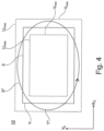
- the laser beam movement unit can be designed to induce a high frequency oscillation of the focal point of the machining laser beam on a focal point oscillation path in the form of a Lissajous figure or a combination of more than one Lissajous figure and to vary the size of the Lissajous figure or the combination of more than one Lissajous figure.
- a further embodiment relates to a use of a device according to one of the above embodiments and modifications for laser cutting a workpiece, in particular a workpiece made of or containing at least one metal.
- One embodiment of the invention relates to a method for laser cutting a workpiece, preferably a workpiece of or comprising at least one metal, and producing workpiece parts with a device for laser cutting a workpiece and producing workpiece parts according to one of the above embodiments and modifications, wherein a laser source for generating a machining laser beam with a power of at least 200 W, preferably at least 1 kW, is provided at the interface, wherein the method comprises the steps of:
- the adjusting includes optimising the movement trajectory by redundantly partitioning the movement trajectory of the machining laser beam between the cutting head movement unit and the laser beam movement unit.
- At least one parameter selected from the movement parameter of the cutting head movement unit, the movement parameter of the laser beam movement unit and the parameter of a deviation of a cut contour from the predetermined contour can be adjusted, e.g. increased or reduced, and/or optimised and/or thus predetermined.
- at least one of the respective other parameters can be optimised and/or thus predetermined.
- the adjusting and/or optimising can include increasing at least one rounding tolerance of the cutting head movement unit and/or at least one dynamic limit of the cutting head movement unit.
- a movement parameter of the dynamic laser beam movement unit can be adapted and/or optimised, in order to optimise the eventual movement trajectory of the machining laser beam.
- the adjustment can be performed based on at least one increased rounding tolerance of the cutting head movement unit.
- the adjustment can further include compensating for the deviation of the cut contour from the predetermined contour resulting from the at least one increased rounding tolerance.
- the memory unit can store a machine model representing the kinematic behaviour of the moving cutting head and estimating state data of the cutting head movement as a movement parameter of the cutting head movement unit and as a further parameter a resulting deviation of the cut contour from the predetermined contour, and wherein the adjustment includes reading the machine model from the memory unit into the optimisation module.
- the adjustment can be performed based on at least one increased dynamic limit of the cutting head movement unit.
- the adjustment can further include compensating for the deviation of the cut contour from the predetermined contour resulting from the at least one increased dynamic limit.
- the memory unit can store a process model representing the laser cutting process and estimating as parameters state data of the laser cutting process and a resulting deviation of the cut contour from the predetermined contour, and wherein the adjustment comprises reading the process model from the memory unit into the optimisation module.
- a deviation between corresponding actual state data and corresponding target state data can be estimated.
- the method can be performed after a previous laser cutting of the workpiece, which was performed with the at least one movement trajectory determined by the determination module, in particular without using the optimisation module.
- surface defects on the workpiece, in particular on the cut edge such as adhering melt and/or melt droplets and burrs, can be reduced and/or removed by re-machining the produced workpiece parts with the machining laser beam optimised by the optimisation module and targeted melting and blowing out with a cutting gas or vaporisation.
- the movement trajectory also referred to as the trajectory, is understood to mean the temporal processing of the movement trajectory curves or movement trajectory points for the machining laser beam obtained by the determination module and/or the optimisation module.
- the movement trajectory can comprise at least one segment of the movement path for the machining laser.
- dynamic laser beam movement unit and “laser beam movement unit” are used synonymously here.
- movement of the machining laser beam via the cutting head and variations thereof mean movement of the machining laser beam by moving the cutting head with the cutting head movement unit.
- cut edge is understood to mean one or more cut edges of a produced, i.e., cut, workpiece part.
- the terms “device for laser cutting a workpiece and for producing workpiece parts” and “device for laser cutting” are used synonymously here.
- the terms “machining laser beam” and “laser beam” are also used synonymously.
- the term “movement trajectory” includes a complete movement trajectory and/or one or more segments of a movement trajectory.
- predetermined contour includes a complete predetermined contour and/or one or more segments of a predetermined contour.
- cut contour includes a complete cut contour and/or one or more segments of a cut contour.
- high frequency beam-shaping movement or “dynamic movement” of the laser beam or “moved at high frequency” or “dynamically moved” laser beam and variations thereof mean in the present context that the laser beam is moved at high frequency, for example at frequencies of 10 Hzto 15 kHz, in particular above 500 Hz.
- dynamic beam shaping means that beam shaping is performed by dynamically movable, orientable and/or adjustable elements of the laser beam movement unit, for example with frequencies of 10 Hz to 15 kHz, in particular above 500 Hz. The same applies to the term “dynamically movable”.
- the laser source for generating a machining laser beam can be designed such that a continuous and/or discontinuous, in particular pulsed, machining laser beam is provided.
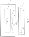
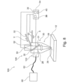
- Figure 1 schematically shows, as a first exemplary embodiment, a device 10 for laser cutting a workpiece 12 and for producing workpiece parts.
- the workpiece 12 is a sheet of precious metal from which workpiece parts with a predetermined contour are produced by laser cutting.
- the device 10 for laser cutting is provided with a cutting head 20.
- the cutting head 20 has an interface 22 for a laser source to generate a machining laser beam 24 with a power of 1 kW.
- the interface 22 is arranged at a first end of the cutting head 20.
- the interface 22 can also be provided on the side of the cutting head 20 to introduce the laser beam 24 laterally into the cutting head.
- An exit aperture 26 for the machining laser beam 24 is provided at a second end of the cutting head 20 opposite the first end.
- Laser beam optics 28 are provided between the interface 22 and the exit aperture 26. If the interface 22 is arranged at the first end of the cutting head, the laser beam 24 is guided through the cutting head by means of the laser beam optics 28 with its direction of propagation being essentially parallel to the central axis of the cutting head. If the interface 22 is provided in one side of the cutting head 20, the laser beam 24 is deflected at least once by means of the laser beam optics 28 and guided through the exit aperture 26 of the cutting head 20.
- the laser beam optics 28 have at least one dynamic laser beam movement unit 30 for producing a high frequency beam-shaping movement, in particular a high frequency oscillation, of the machining laser beam 24 at least perpendicular to its direction of propagation, for example a DBS system.
- a dynamically movable optical element 31 for beam shaping of the laser beam is provided as the dynamic laser beam movement unit 30, which is positioned or can be positioned in the beam path of the laser beam 24.
- the optical element 31 is a focusing lens that can be tilted dynamically with one or more piezo actuators (not shown), which dynamically moves to shape the laser beam 24 and move the machining laser beam 24 perpendicular to its direction of propagation.
- the focusing lens in this example has a mass of approximately 30 g.
- the focusing lens is dynamically movable with the actuator, in particular high frequency movable over one or more time periods, with frequencies above 100 Hz, preferably above 500 Hz.
- At least one movable surface reflecting the machining laser beam 24 is provided as an optical element 31 of the dynamic laser beam movement unit 30, which is arranged and aligned in the beam path in such a way that it deflects the machining beam 24.
- the machining laser beam 24, when introduced laterally into the cutting head 20, can thus be deflected within the cutting head, for example by 90°, before being directed onto the workpiece 12.
- the reflective surface is at least partially dynamically adjustable by means of at least one or more actuators, for example piezo actuators.
- the at least one movable surface can be dynamically adjusted as a whole by means of at least one actuator.
- the at least one movable surface can provide a surface unit of the laser beam guiding device, the surface geometry of which, in particular its curvature, can be dynamically adjusted with actuators.
- the machining laser beam be shaped and/or moved at least perpendicularly to its direction of propagation, but also the divergence of the machining laser beam can be changed and/or the focal position of the machining laser beam can be shifted parallel to its direction of propagation.
- the laser beam movement unit 30 can include, as the optical element 31, a dynamically orientable and planar mirror made of, for example, coated SiC (silicon carbide), which provides the movable surface that reflects the machining laser beam.
- a piezo actuator is provided as the actuator, with which the mirror can be moved dynamically and thereby be oriented.
- the unit consisting of a mirror and at least one actuator is also called a piezo scanner.
- each piezo actuator can be controlled individually.
- it is a piezo actuator based on a modified PZT (lead zirconate titanate) ceramic with a typical drive voltage of 120 V.
- the mirror with the movable surface is tilted by the at least one piezo actuator such that the machining laser beam 24 is deflected.
- the surface is dynamically moved by the piezo actuators, providing suitable tilt angles for the deflection, so that the machining laser beam 24 is dynamically moved.
- the beam parameter product of the machining laser beam 24 and/or the intensity distribution of the laser beam spot on the workpiece 12 is shaped as desired for laser cutting, since the focal point of the machining laser beam 24 is dynamically moved to be at least perpendicular to its direction of propagation at frequencies between, for example, 10 Hz and 15 kHz, thus shaping the laser beam spot striking the workpiece.
- the laser beam movement unit 30 includes as the optical element 31 at least two movable reflective surfaces that are part of a galvanometer scanner.
- the galvanometer scanner can contain two mirrors, each of which provides a movable surface. These can be moved individually and dynamically as actuators, for example by means of individually controllable galvanometers.
- the galvanometer scanner is provided, for example, with two mirrors orientable such that the machining laser beam 24 is deflected at least once at an angle greater than 90° and at least once at an angle smaller than 90°.
- the two mirrors are oriented and moved relative to one another such that the machining laser beam 15 is deflected twice and is simultaneously dynamically moved.
- almost any intensity distributions of the beam spot and/or any beam parameter products of the machining laser beam 24 can be provided by means of dynamic beam shaping.
- the laser beam movement unit 30 has, as the reflective dynamically movable surface of the optical element 31, a segment mirror with a plurality of separate mirror segments arranged to be adjacent to one another to form a pattern.
- Each mirror segment has, for example, a gold coating, is reflective for the machining laser beam 24 and can be individually dynamically oriented by means of a piezo actuator.
- the laser beam movement unit 30 thus provides a segmented overall surface reflecting the machining laser beam 24, the surface geometry of which, in particular its curvature, is highly dynamically adjustable.
- the segment mirror is used for dynamic beam shaping.
- the surface of the segment mirror is changed with a sufficiently high frequency above 10 Hz, in particular above 100 Hz, such that the resulting focus on the workpiece 12 is moved dynamically at least laterally to the direction of propagation of the laser beam.
- the beam parameter product and/or the intensity distribution of the time-integrated machining laser beam can be modified as desired by the dynamic beam shaping.
- the laser beam movement unit 30 has a deformable mirror (DM, Dynamic Mirror) as a dynamic beam-shaping optical element 31 to provide a movable, reflective, continuous surface.
- the mirror is formed by a membrane made of deformable material, which is dynamically deformable by means of the actuators.
- a membrane made of deformable material, which is dynamically deformable by means of the actuators.
- the top of the membrane is coated with a highly reflective dielectric multilayer coating, which is suitable for laser beams up to 120 kW at a wavelength of 1060 to 1090 nm.
- the movable, reflective, continuous surface of the deformable mirror (DM, dynamic mirror) can be operated in the same way as the previously described segment mirror.
- the device 10 for laser cutting further includes a cutting head movement unit 32 which moves the cutting head 20, and thus the machining laser beam 24 guided therein, over the workpiece 12 at least in the X and/or Y direction.
- the cutting head 20 is mounted on a carriage (not shown) which is movable in the X direction on a bridge (not shown) which is movable in the Y direction, as schematically illustrated with arrows in Figure 1 .
- the inertial components of the cutting head movement unit 32 and the cutting head 20 have a combined mass of approximately 400 kg in this example.
- a movement of the cutting head 20 in the Z direction i.e., in a direction perpendicular to the workpiece, can also be performed with the cutting head movement unit 32.
- the device 10 for laser cutting is provided with a control unit 34 for controlling the cutting head movement unit 32 and the laser beam movement unit 30.
- the control unit 34 is connected, wirelessly or wired, in a data-transmitting manner to the cutting head movement unit 32 and the laser beam movement unit 30.
- the control unit 34 has a determination module 36 with which at least one movement trajectory of the machining laser beam 24 over the workpiece 12 can be determined. The movement trajectory is determined in at least one workpiece plane according to at least one predetermined contour of the workpiece parts to be produced.
- the control unit 34 further comprises a memory unit 38 in which at least one predetermined parameter selected from a movement parameter of the cutting head movement unit 32, a movement parameter of the laser beam movement unit 30 and a parameter of a deviation of a cut contour from the predetermined contour is stored and retrievable therefrom.
- the control unit 34 also includes an optimisation module 40 for adjusting the movement trajectory.
- the adjustment, i.e., optimisation, of the movement trajectory of the machining laser beam 24 is performed by overlaying the movement of the machining laser beam 24 via the cutting head 20 with the high frequency, beam-shaping movement of the machining laser beam 24 via the laser beam movement unit 30 on the basis of the at least one predetermined parameter retrievable from the memory unit 38.
- step S1 At least one movement trajectory X, Y of the machining laser beam 24 in at least one workpiece plane is determined by means of the determination module 40 of the control unit 34 in accordance with at least one predetermined contour X, Y of the workpiece parts to be produced.
- step S2 the optimisation module 40 of the control unit 34 adjusts the movement trajectory by overlaying the movement of the machining laser beam via the cutting head 20 with the high frequency beam-shaping movement of the machining laser beam via the dynamic laser beam movement unit 30 based on the at least one predetermined parameter retrievable from the memory unit 38.
- the movement trajectory is optimised by the optimisation module 40 by assigning a movement trajectory X*, Y* to the cutting head movement unit 32 and deflections U, V of the optical element, U in the X direction and V in the Y direction, to the laser beam movement unit 30, resulting in an adjusted movement trajectory X°, Y°.
- the machining laser beam 24 is generated with a power of at least 200 W, preferably at least 1 kW, and the workpiece 12 is cut with the machining laser beam 24.
- the optical element of the laser beam movement unit 30 can be an off-axis parabolic mirror having a centre with which the machining laser beam 24 is deflected and its focal point is oscillated on a focal point oscillation path.
- the cutting quality can be additionally improved, in particular the cutting quality for workpieces of higher thickness.
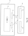
- Figure 10 schematically illustrates the interaction of the components of the device 100 for laser cutting according to an eighth exemplary embodiment.
- the eighth exemplary embodiment is a modification of the seventh exemplary embodiment.
- No detector 50 is provided on the device 100 in the eighth exemplary embodiment.
- a model MOD for estimating surface defects is stored in the memory unit 38 and is retrievable by the optimisation module 40.
- a model MOD for estimating surface defects for example, a model for estimating scoring can be used, with which the roughness, i.e., the amplitude and frequency, of the scores of the cut edge can be calculated by a damped oscillator with a disruptive term.
- the roughness can be modelled by an adaptive neuro-fuzzy inference system (ANFIS).
- AFIS adaptive neuro-fuzzy inference system
- the original movement trajectory X, Y of the cutting head 20 to be performed by the mechanical axes of the cutting head movement unit 32 is therefore not changed.
- an adjusted movement trajectory X°, Y° is obtained.
- the methods performable by the devices of the first to eighth exemplary embodiments can be performed after a previous laser cutting of the workpiece 12 performed with the at least one movement trajectory determined by the determination module 36 without using the optimisation module 40.
- melt and/or melt droplets adhering to the workpiece 12, in particular to the cut edge, and burrs or other surface defects, such as scoring can be reduced and/or removed by re-machining the workpiece or the produced workpiece parts with the machining laser beam 24 optimised by the optimisation module 40 and targeted melting and blowing out with a cutting gas or vaporisation.
Landscapes
- Physics & Mathematics (AREA)
- Optics & Photonics (AREA)
- Engineering & Computer Science (AREA)
- Plasma & Fusion (AREA)
- Mechanical Engineering (AREA)
- Robotics (AREA)
- Laser Beam Processing (AREA)
Claims (15)
- Dispositif (10 ; 100) de découpe laser d'une pièce (12) et de production de parties de pièce, comportant une tête de découpe (20),la tête de découpe comportant une interface (22) pour une source laser afin de générer un faisceau laser (24) d'usinage d'une puissance d'au moins 200 W, de préférence d'au moins 1 kW, une ouverture de sortie (26) pour le faisceau laser d'usinage, et une optique (28) de faisceau laser entre l'interface et l'ouverture de sortie,l'optique (28) de faisceau laser comportant au moins une unité de déplacement (30) dynamique de faisceau laser pour générer un déplacement de mise en forme de faisceau à haute fréquence du faisceau laser d'usinage au moins perpendiculairement à sa direction de propagation ;comportant une unité de déplacement (32) de la tête de découpe pour réaliser un déplacement du faisceau laser d'usinage sur la pièce (12) par l'intermédiaire de la tête de découpe (20) ; etune unité de commande (34) pour commander l'unité de déplacement (32) de tête de découpe et l'unité de déplacement (30) de faisceau laser,l'unité de commande comprenant- un module de détermination (36) pour déterminer au moins une trajectoire de déplacement (X, Y) du faisceau laser d'usinage dans au moins un plan de pièce en fonction d'au moins un contour (X, Y) prédéterminé des parties de pièce à produire ; et- une unité de mémoire (38) à partir de laquelle au moins un paramètre prédéterminé, sélectionné parmi un paramètre de déplacement de l'unité de déplacement (32) de tête de découpe, un paramètre de déplacement de l'unité de déplacement (30) de faisceau laser et un paramètre d'un écart d'un contour de découpe par rapport au contour prédéterminé, peut être récupéré ;caractérisé en ce que l'unité de commande comprend- un module d'optimisation (40) pour ajuster la trajectoire de déplacement (X, Y) par superposition du déplacement du faisceau laser d'usinage par l'intermédiaire de la tête de découpe (20) avec le déplacement de mise en forme de faisceau à haute fréquence du faisceau laser d'usinage par l'intermédiaire de l'unité de déplacement (30) de faisceau laser en fonction de l'au moins un paramètre prédéterminé récupérable à partir de l'unité de mémoire (38) ;dans lequel le module d'optimisation (40) est configuré pour optimiser la trajectoire de déplacement (X ; Y) par partitionnement de manière redondante de la trajectoire de déplacement du faisceau laser d'usinage entre l'unité de déplacement (32) de tête de découpe et l'unité de déplacement (30) de faisceau laser.
- Dispositif selon la revendication 1,
dans lequel le module d'optimisation (40) est configuré pour ajuster et/ou optimiser au moins un paramètre sélectionné parmi le paramètre de déplacement de l'unité de déplacement (32) de tête de découpe, le paramètre de déplacement de l'unité de déplacement (30) de faisceau laser et le paramètre d'un écart d'un contour de découpe par rapport au contour prédéterminé, en particulier pour prédéterminer l'au moins un paramètre prédéterminé. - Dispositif selon la revendication 1 ou 2,dans lequel le paramètre de déplacement de l'unité de déplacement de tête de découpe est au moins un paramètre sélectionné parmi- une limite dynamique (DG) de l'unité de déplacement de tête de découpe,- une tolérance d'arrondi (VT) de l'unité de déplacement de tête de découpe à un angle du contour prédéterminé, et- une tolérance d'arrondi (VT) de l'unité de déplacement de tête de découpe à un rayon du contour prédéterminé ;et/oudans lequel le paramètre de déplacement de l'unité de déplacement de faisceau laser est au moins un paramètre sélectionné parmi- une limite dynamique (DG) de l'unité de déplacement de faisceau laser et- une amplitude de déplacement maximale du faisceau laser d'usinage, laquelle peut être générée à l'aide de l'unité de déplacement de faisceau laser.
- Dispositif selon l'une quelconque des revendications précédentes,
dans lequel le paramètre d'un écart d'un contour de coupe par rapport au contour (X, Y) prédéterminé est au moins un paramètre sélectionné parmi- un écart estimé,- un paramètre résultant d'un écart mesuré,- un arrondi du contour découpé à un angle du contour prédéterminé,- un arrondi du contour découpé à un rayon du contour prédéterminé,- un défaut de surface (OD) estimé d'un bord découpé, et- un paramètre résultant d'un défaut de surface mesuré d'un bord découpé. - Dispositif selon l'une quelconque des revendications précédentes,
dans lequel le module d'optimisation (40) pour ajuster la trajectoire de déplacement est conçu en fonction d'au moins une tolérance d'arrondi (VT) accrue de l'unité de déplacement (32) de tête de découpe et sert à compenser l'écart résultant du contour de découpe par rapport au contour prédéterminé. - Dispositif selon l'une quelconque des revendications précédentes,
dans lequel un modèle de machine (MM) représentant le comportement cinématique de la tête de découpe (20) mobile est mémorisé dans l'unité de mémoire (38) et estime, en tant que paramètre de déplacement de l'unité de déplacement de tête de découpe, des données d'état du déplacement de tête de découpe et, en tant qu'autre paramètre, un écart résultant du contour de découpe par rapport au contour prédéterminé, et dans lequel le module d'optimisation (40) est en communication de données avec l'unité de mémoire (38) pour lire le modèle de machine. - Dispositif selon l'une quelconque des revendications précédentes,
dans lequel le module d'optimisation est conçu pour ajuster la trajectoire de déplacement en fonction d'au moins une limite dynamique (DG) accrue de l'unité de déplacement (32) de tête de découpe. - Dispositif selon l'une quelconque des revendications précédentes,
dans lequel un modèle de processus, représentant le processus de découpe laser et estimant comme paramètres des données d'état du processus de découpe laser et un écart résultant du contour de découpe par rapport au contour prédéterminé, est mémorisé dans l'unité de mémoire (38), et dans lequel le module d'optimisation (40) est en communication de données avec l'unité de mémoire pour lire le modèle de processus. - Dispositif selon l'une quelconque des revendications précédentes,dans lequel l'unité de commande (34) comprend une base de données de figures de Lissajous bidimensionnelles et/ou tridimensionnelles prédéterminées et l'unité de déplacement (30) de faisceau laser est conçue pour induire une oscillation à haute fréquence du point focal du faisceau laser d'usinage sur un trajet d'oscillation de point focal sous la forme d'une figure de Lissajous ou d'une combinaison de plusieurs figures de Lissajous en fonction de la base de données ; et/oudans lequel un dispositif détecteur (50) connecté de manière à transmettre des données à l'unité de mémoire (38) est fourni sur ou dans la tête de découpe (20) pour mesurer un défaut de surface d'un bord de découpe, en particulier un marquage, en tant que paramètre d'un écart du contour de découpe par rapport au contour (X, Y) prédéterminé ; et/ou dans lequel un modèle (MOD) pour estimer un défaut de surface d'un bord de découpe, en particulier de marquage, est mémorisé dans l'unité de mémoire (38), laquelle estime comme paramètre un défaut de surface (OD) et un écart résultant du contour de découpe par rapport au contour prédéterminé, et dans lequel le module d'optimisation (40) est en communication de données avec l'unité de mémoire pour lire le modèle afin d'estimer un défaut de surface.
- Procédé de découpe laser d'une pièce (12) et de production de parties de pièce à l'aide d'un dispositif (10 ; 100) de découpe laser d'une pièce et de production de parties de pièce selon l'une des revendications 1 à 9, dans lequel une source laser (60, 62) pour générer un faisceau laser d'usinage d'une puissance d'au moins 200 W, de préférence d'au moins 1 kW, est fournie au niveau de l'interface (22),le procédé comprenant les étapes suivantes- la détermination, au moyen du module de détermination (36) de l'unité de commande (34), d'au moins une trajectoire de déplacement du faisceau laser (24) d'usinage dans au moins un plan de pièce en fonction d'au moins un contour (X, Y) prédéterminé des parties de pièce (S1) à produire ;- l'ajustement, au moyen du module d'optimisation (40) de l'unité de commande (34), de la trajectoire de déplacement par superposition du déplacement du faisceau laser d'usinage par l'intermédiaire de la tête de découpe (20) avec le déplacement de mise en forme de faisceau à haute fréquence du faisceau laser d'usinage par l'intermédiaire de l'unité de déplacement (30) dynamique de faisceau laser en fonction de l'au moins un paramètre (S2) prédéterminé récupérable à partir de l'unité de mémoire ;- la production du faisceau laser (24) d'usinage d'une puissance d'au moins 200 W, de préférence d'au moins 1 kW, et la découpe de la pièce à l'aide du faisceau laser (S3) d'usinage ; et- le déplacement du faisceau laser (24) d'usinage sur la pièce par l'intermédiaire de la tête de découpe (20) et la réalisation d'un déplacement de mise en forme de faisceau à haute fréquence du faisceau laser d'usinage au moins perpendiculairement à sa direction de propagation par l'intermédiaire de l'unité de déplacement (30) de faisceau laser en fonction de la trajectoire de déplacement (X°, Y°) ajustée (S4) ;dans lequel l'ajustement comprend l'optimisation de la trajectoire de déplacement (X ; Y) par partitionnement de manière redondante de la trajectoire de déplacement du faisceau laser (24) d'usinage entre l'unité de déplacement (32) de tête de découpe et l'unité de déplacement (30) de faisceau laser.
- Procédé selon la revendication 10,dans lequel au moins un paramètre sélectionné parmi le paramètre de déplacement de l'unité de déplacement (32) de tête de découpe, le paramètre de déplacement de l'unité de déplacement (30) de faisceau laser et le paramètre d'un écart d'un contour de découpe par rapport au contour prédéterminé est ajusté et/ou optimisé, en particulier pour prédéterminer l'au moins un paramètre prédéterminé ; et/oudans lequel l'ajustement est réalisé en fonction d'au moins une tolérance d'arrondi (VT) accrue de l'unité de déplacement (32) de tête de découpe et comprend la compensation de l'écart résultant du contour de découpe par rapport au contour prédéterminé.
- Procédé selon l'une quelconque des revendications 10 à 11,dans lequel un modèle de machine (MM) représentant le comportement cinématique de la tête de découpe (20) mobile est mémorisé dans l'unité de mémoire (38) et estime, en tant que paramètre de déplacement de l'unité de déplacement (32) de tête de découpe, des données d'état du déplacement de tête de découpe et, en tant qu'autre paramètre, un écart résultant du contour de découpe par rapport au contour prédéterminé, et dans lequel l'ajustement comprend la lecture du modèle de machine à partir de l'unité de mémoire dans le module d'optimisation (40) ; et/oudans lequel l'ajustement est réalisé en fonction d'au moins une limite dynamique (DG) accrue de l'unité de déplacement (32) de tête de découpe.
- Procédé selon l'une quelconque des revendications 10 à 12,dans lequel l'unité de mémoire (38) mémorise un modèle de processus représentant le processus de découpe laser et estimant en tant que paramètres des données d'état du processus de découpe laser et un écart résultant du contour de découpe par rapport au contour prédéterminé, et dans lequel l'ajustement comprend la lecture du modèle de processus à partir de l'unité de mémoire dans le module d'optimisation ; et/oudans lequel l'unité de commande (38) comprend une base de données de figures de Lissajous bidimensionnelles et/ou tridimensionnelles prédéterminées et l'unité de déplacement (30) de faisceau laser induit une oscillation à haute fréquence du point focal du faisceau laser d'usinage sur un trajet d'oscillation de point focal sous la forme d'une figure de Lissajous ou d'une combinaison de plusieurs figures de Lissajous en fonction de la base de données.
- Procédé selon l'une quelconque des revendications 10 à 13,dans lequel un dispositif détecteur (50) connecté de manière à transmettre des données à l'unité de mémoire (38) est fourni sur ou dans la tête de découpe (120) et le dispositif détecteur mesure un défaut de surface d'un bord de découpe, en particulier un marquage, en tant que paramètre d'un écart du contour de découpe par rapport au contour prédéterminé ; et/oudans lequel un modèle (MOD) pour estimer un défaut de surface du bord de découpe, en particulier de marquage, est mémorisé dans l'unité de mémoire (38), laquelle estime en tant que paramètre un défaut de surface et un écart résultant du contour de découpe par rapport au contour prédéterminé, et dans lequel l'ajustement comprend la lecture du modèle pour l'estimation d'un défaut de surface à partir de l'unité de mémoire (38) dans le module d'optimisation (40) ; et/oudans lequel le procédé est mis en oeuvre après une découpe laser préalable de la pièce réalisée à l'aide de l'au moins une trajectoire de déplacement déterminée par le module de détermination (38).
- Produit de programme informatique comprenant au moins un module de programme, lequel amène le dispositif selon l'une quelconque des revendications 1 à 9 à mettre en oeuvre les étapes de procédé selon l'une quelconque des revendications 10 à 14, en particulier lorsque les modules de programme sont chargés dans une mémoire du dispositif, en particulier comprenant au moins un élément choisi parmi le module de détermination et le module d'optimisation.
Applications Claiming Priority (2)
| Application Number | Priority Date | Filing Date | Title |
|---|---|---|---|
| EP21161527.3A EP4056309A1 (fr) | 2021-03-09 | 2021-03-09 | Dispositif et procédé de découpe laser d'une pièce et production de pièces |
| PCT/EP2022/056022 WO2022189499A1 (fr) | 2021-03-09 | 2022-03-09 | Dispositif et procédé de découpe au laser d'une pièce et de production de parties de pièces |
Publications (2)
| Publication Number | Publication Date |
|---|---|
| EP4304802A1 EP4304802A1 (fr) | 2024-01-17 |
| EP4304802B1 true EP4304802B1 (fr) | 2025-01-29 |
Family
ID=74870583
Family Applications (2)
| Application Number | Title | Priority Date | Filing Date |
|---|---|---|---|
| EP21161527.3A Withdrawn EP4056309A1 (fr) | 2021-03-09 | 2021-03-09 | Dispositif et procédé de découpe laser d'une pièce et production de pièces |
| EP22711546.6A Active EP4304802B1 (fr) | 2021-03-09 | 2022-03-09 | Dispositif et procédé de découpe laser d'une pièce et production de pièces |
Family Applications Before (1)
| Application Number | Title | Priority Date | Filing Date |
|---|---|---|---|
| EP21161527.3A Withdrawn EP4056309A1 (fr) | 2021-03-09 | 2021-03-09 | Dispositif et procédé de découpe laser d'une pièce et production de pièces |
Country Status (5)
| Country | Link |
|---|---|
| US (1) | US12042880B2 (fr) |
| EP (2) | EP4056309A1 (fr) |
| JP (1) | JP7490898B2 (fr) |
| CN (1) | CN116669891B (fr) |
| WO (1) | WO2022189499A1 (fr) |
Families Citing this family (16)
| Publication number | Priority date | Publication date | Assignee | Title |
|---|---|---|---|---|
| KR102875674B1 (ko) * | 2020-07-21 | 2025-10-23 | 삼성디스플레이 주식회사 | 레이저 장치 및 표시 장치의 제조 방법 |
| WO2022205082A1 (fr) * | 2021-03-31 | 2022-10-06 | Yangtze Memory Technologies Co., Ltd. | Système laser destiné au découpage en dés d'une structure semi-conductrice et procédé de fonctionnement associé |
| DE102023105580A1 (de) * | 2023-03-07 | 2024-09-12 | TRUMPF Werkzeugmaschinen SE + Co. KG | Computerimplementiertes Verfahren zum Bestimmen von Schnittspaltbreiten für ein Laserschneidverfahren |
| CN116275217B (zh) * | 2023-03-14 | 2025-09-12 | 东北林业大学 | 一种利用李萨茹图形轨迹运动加工微通道结构的方法 |
| CN116871709B (zh) * | 2023-09-08 | 2023-12-08 | 常州市鹏瑞自动化设备有限公司 | 激光切割异形圆管件的方法 |
| CN117020399B (zh) * | 2023-10-10 | 2023-12-08 | 深圳市艾姆克斯科技有限公司 | 一种激光机调整光束聚焦的处理方法及系统 |
| DE102024106331A1 (de) * | 2024-03-05 | 2025-09-11 | TRUMPF Werkzeugmaschinen SE + Co. KG | Verfahren zum bearbeiten eines metallischen werkstücks sowie lasereinrichtung |
| CN118884899B (zh) * | 2024-09-30 | 2025-01-14 | 深圳市常丰激光刀模有限公司 | 智能模具的生产控制方法、装置、设备及存储介质 |
| CN119347779B (zh) * | 2024-11-29 | 2025-06-06 | 福建泉州环清电力设备有限公司 | 一种激光切割机寻轨路径规划优化方法及系统 |
| CN119689975B (zh) * | 2024-12-31 | 2025-09-09 | 昆山冠业达精密工业有限公司 | 用于异形零件的数控切割路径优化方法及系统 |
| CN119536125A (zh) * | 2025-01-08 | 2025-02-28 | 天津市诚智泰新能源科技有限公司 | 应用于激光切管机的多维度切割精度控制系统 |
| CN119810096B (zh) * | 2025-03-12 | 2025-06-27 | 深圳市正泰隆科技有限公司 | 一种抗蚀铝合金件的智能检测装置及检测方法 |
| CN120428652B (zh) * | 2025-04-30 | 2026-03-13 | 江苏麦森激光科技有限公司 | 一种激光切割自动控制方法及控制系统 |
| CN120395143B (zh) * | 2025-06-23 | 2025-11-07 | 江苏康业金属制品有限公司 | 一种工字轮缝隙处理用无缝焊接系统及其工艺 |
| CN120395196A (zh) * | 2025-06-26 | 2025-08-01 | 广州市君圣德纸业有限公司 | 一种基于人工智能的纸制品加工用激光切割装置 |
| CN121325770B (zh) * | 2025-10-30 | 2026-04-07 | 江苏和熠光显科技有限公司 | 用于oled柔性屏生产的异形切割控制方法、系统及存储介质 |
Citations (1)
| Publication number | Priority date | Publication date | Assignee | Title |
|---|---|---|---|---|
| DE102019115554A1 (de) * | 2019-06-07 | 2020-12-10 | Bystronic Laser Ag | Bearbeitungsvorrichtung zur Laserbearbeitung eines Werkstücks und Verfahren zur Laserbearbeitung eines Werkstücks |
Family Cites Families (22)
| Publication number | Priority date | Publication date | Assignee | Title |
|---|---|---|---|---|
| DE2821883C2 (de) | 1978-05-19 | 1980-07-17 | Ibm Deutschland Gmbh, 7000 Stuttgart | Vorrichtung zur Materialbearbeitung |
| US4532402A (en) | 1983-09-02 | 1985-07-30 | Xrl, Inc. | Method and apparatus for positioning a focused beam on an integrated circuit |
| US5109148A (en) | 1990-01-26 | 1992-04-28 | Mitsubishi Denki Kabushiki Kaisha | Positioning device for a machining apparatus |
| US5751585A (en) | 1995-03-20 | 1998-05-12 | Electro Scientific Industries, Inc. | High speed, high accuracy multi-stage tool positioning system |
| ITTO20050016A1 (it) | 2005-01-13 | 2006-07-14 | Prima Ind Spa | Macchina operatrice laser |
| ITTO20050578A1 (it) | 2005-08-16 | 2007-02-17 | Prima Ind Spa | Procedimento di gestione di sistemi dotati di attuatori ridondanti |
| DE102008053397B4 (de) | 2008-05-20 | 2012-12-27 | Fraunhofer-Gesellschaft zur Förderung der angewandten Forschung e.V. | Verfahren zum Schmelzschneiden von Werkstücken mit Laserstrahlung |
| DE102008027524B3 (de) * | 2008-06-04 | 2009-09-17 | Fraunhofer-Gesellschaft zur Förderung der angewandten Forschung e.V. | Vorrichtung und Verfahren zum schneidenden Bearbeiten von Werkstücken mit einem Laserstrahl |
| DE102010003750A1 (de) | 2010-04-08 | 2011-10-13 | Trumpf Laser- Und Systemtechnik Gmbh | Verfahren und Anordnung zum Verändern der Strahlprofilcharakteristik eines Laserstrahls mittels einer Mehrfachclad-Faser |
| JP5602300B2 (ja) | 2011-05-30 | 2014-10-08 | 三菱重工業株式会社 | レーザ加工ヘッド、レーザ加工装置、レーザ加工装置の光学系、レーザ加工方法、及びレーザ集束方法 |
| JP6063670B2 (ja) | 2011-09-16 | 2017-01-18 | 株式会社アマダホールディングス | レーザ切断加工方法及び装置 |
| US9250390B2 (en) | 2011-12-09 | 2016-02-02 | Lumentum Operations Llc | Varying beam parameter product of a laser beam |
| JP5832412B2 (ja) | 2012-11-12 | 2015-12-16 | 三菱重工業株式会社 | 光学系及びレーザ加工装置 |
| DE102013102442B4 (de) | 2013-03-12 | 2014-11-27 | Highyag Lasertechnologie Gmbh | Optische Vorrichtung zur Strahlformung |
| JP5941113B2 (ja) | 2014-09-30 | 2016-06-29 | ファナック株式会社 | 集光径を拡大できるレーザ加工装置 |
| DE102015101263B4 (de) | 2015-01-28 | 2016-12-15 | Precitec Gmbh & Co. Kg | Vorrichtung zur Materialbearbeitung mittels Laserstrahlung |
| CN107999967B (zh) * | 2017-11-30 | 2019-05-31 | 华中科技大学 | 一种大型三维零件表面并行激光刻蚀加工方法和装置 |
| EP3517241A1 (fr) * | 2018-01-29 | 2019-07-31 | Bystronic Laser AG | Dispositif optique permettant de mettre en forme un faisceau d'ondes électromagnétiques et son utilisation, dispositif de traitement de faisceau et son utilisation et procédé de traitement de faisceau |
| WO2019188155A1 (fr) * | 2018-03-26 | 2019-10-03 | パナソニックIpマネジメント株式会社 | Dispositif de découpe au laser et procédé de découpe au laser |
| DE102018220336A1 (de) * | 2018-11-27 | 2020-01-09 | Fraunhofer-Gesellschaft zur Förderung der angewandten Forschung e.V. | Vorrichtung und Verfahren zur Strahlformung und Strahlmodulation bei einer Lasermaterialbearbeitung |
| EP3747588A1 (fr) * | 2019-06-07 | 2020-12-09 | Bystronic Laser AG | Dispositif d'usinage destiné à l'usinage laser d'une pièce et procédé d'usinage laser d'une pièce |
| DE102019120830A1 (de) * | 2019-08-01 | 2021-02-04 | Scanlab Gmbh | Führungsvorrichtung zum Führen eines Laserstrahls zur Materialbearbeitung und/oder für medizinische Behandlungen |
-
2021
- 2021-03-09 EP EP21161527.3A patent/EP4056309A1/fr not_active Withdrawn
-
2022
- 2022-03-09 EP EP22711546.6A patent/EP4304802B1/fr active Active
- 2022-03-09 US US18/263,785 patent/US12042880B2/en active Active
- 2022-03-09 CN CN202280008430.0A patent/CN116669891B/zh active Active
- 2022-03-09 WO PCT/EP2022/056022 patent/WO2022189499A1/fr not_active Ceased
- 2022-03-09 JP JP2023540843A patent/JP7490898B2/ja active Active
Patent Citations (1)
| Publication number | Priority date | Publication date | Assignee | Title |
|---|---|---|---|---|
| DE102019115554A1 (de) * | 2019-06-07 | 2020-12-10 | Bystronic Laser Ag | Bearbeitungsvorrichtung zur Laserbearbeitung eines Werkstücks und Verfahren zur Laserbearbeitung eines Werkstücks |
Also Published As
| Publication number | Publication date |
|---|---|
| EP4304802A1 (fr) | 2024-01-17 |
| CN116669891B (zh) | 2024-07-30 |
| US20240033858A1 (en) | 2024-02-01 |
| CN116669891A (zh) | 2023-08-29 |
| WO2022189499A1 (fr) | 2022-09-15 |
| JP2023553511A (ja) | 2023-12-21 |
| JP7490898B2 (ja) | 2024-05-27 |
| US12042880B2 (en) | 2024-07-23 |
| EP4056309A1 (fr) | 2022-09-14 |
Similar Documents
| Publication | Publication Date | Title |
|---|---|---|
| EP4304802B1 (fr) | Dispositif et procédé de découpe laser d'une pièce et production de pièces | |
| JP7717128B2 (ja) | 多軸工作機械 | |
| EP4146429B1 (fr) | Méthode, unité de regulation et système de coupage laser pour la planification combinée des pistes et des processus laser pour systèmes en temps réel très dynamiques | |
| JP7464678B2 (ja) | 加工物のレーザ加工のための機械加工装置および加工物のレーザ加工のための方法 | |
| EP3541566B1 (fr) | Procédé de controle du taux de refroidissement d'un bain de fusion d'un lit de poudre, et système de fabrication par fusion directe de métal par laser avec un scanner laser "in-line" | |
| US6811069B2 (en) | Method and device for the separation of flat workpieces made from a brittle material | |
| US20220410315A1 (en) | Multi-axis machine tool, methods of controlling the same and related arrangements | |
| EP3049212B1 (fr) | Procédé de traitement par laser, système de traitement par laser et tête optique capable de dithering | |
| US11420288B2 (en) | Laser machining systems and methods | |
| JP4553967B2 (ja) | 切削加工装置、加工方法、およびその加工方法で加工した金型 | |
| GB2354845A (en) | Real time control of laser beam characteristics in a laser equipped machine tool | |
| US7371993B2 (en) | Method for laser micromachining | |
| KR100664573B1 (ko) | 레이저 가공 장치 및 방법 | |
| JP2020516459A (ja) | 動作レーザビームの焦点を制御するための方法及び装置ならびにそのような装置を有するレーザ加工ヘッド | |
| WO2024256562A1 (fr) | Dispositif d'usinage au laser pour l'usinage d'une pièce, son utilisation, procédé d'usinage au laser d'une pièce et produit-programme informatique correspondant | |
| JP2017001904A (ja) | ガラス基板のレーザ加工装置 | |
| Ukar et al. | 2D Scan-Head Motion Characterization and Machine-Tool Integration |
Legal Events
| Date | Code | Title | Description |
|---|---|---|---|
| STAA | Information on the status of an ep patent application or granted ep patent |
Free format text: STATUS: UNKNOWN |
|
| STAA | Information on the status of an ep patent application or granted ep patent |
Free format text: STATUS: THE INTERNATIONAL PUBLICATION HAS BEEN MADE |
|
| PUAI | Public reference made under article 153(3) epc to a published international application that has entered the european phase |
Free format text: ORIGINAL CODE: 0009012 |
|
| STAA | Information on the status of an ep patent application or granted ep patent |
Free format text: STATUS: REQUEST FOR EXAMINATION WAS MADE |
|
| 17P | Request for examination filed |
Effective date: 20230503 |
|
| AK | Designated contracting states |
Kind code of ref document: A1 Designated state(s): AL AT BE BG CH CY CZ DE DK EE ES FI FR GB GR HR HU IE IS IT LI LT LU LV MC MK MT NL NO PL PT RO RS SE SI SK SM TR |
|
| DAV | Request for validation of the european patent (deleted) | ||
| DAX | Request for extension of the european patent (deleted) | ||
| GRAP | Despatch of communication of intention to grant a patent |
Free format text: ORIGINAL CODE: EPIDOSNIGR1 |
|
| STAA | Information on the status of an ep patent application or granted ep patent |
Free format text: STATUS: GRANT OF PATENT IS INTENDED |
|
| INTG | Intention to grant announced |
Effective date: 20240925 |
|
| GRAS | Grant fee paid |
Free format text: ORIGINAL CODE: EPIDOSNIGR3 |
|
| GRAA | (expected) grant |
Free format text: ORIGINAL CODE: 0009210 |
|
| STAA | Information on the status of an ep patent application or granted ep patent |
Free format text: STATUS: THE PATENT HAS BEEN GRANTED |
|
| AK | Designated contracting states |
Kind code of ref document: B1 Designated state(s): AL AT BE BG CH CY CZ DE DK EE ES FI FR GB GR HR HU IE IS IT LI LT LU LV MC MK MT NL NO PL PT RO RS SE SI SK SM TR |
|
| REG | Reference to a national code |
Ref country code: GB Ref legal event code: FG4D |
|
| REG | Reference to a national code |
Ref country code: CH Ref legal event code: EP |
|
| REG | Reference to a national code |
Ref country code: DE Ref legal event code: R096 Ref document number: 602022010166 Country of ref document: DE |
|
| REG | Reference to a national code |
Ref country code: IE Ref legal event code: FG4D |
|
| P01 | Opt-out of the competence of the unified patent court (upc) registered |
Free format text: CASE NUMBER: APP_5201/2025 Effective date: 20250131 |
|
| PGFP | Annual fee paid to national office [announced via postgrant information from national office to epo] |
Ref country code: AT Payment date: 20250417 Year of fee payment: 4 |
|
| REG | Reference to a national code |
Ref country code: NL Ref legal event code: MP Effective date: 20250129 |
|
| PG25 | Lapsed in a contracting state [announced via postgrant information from national office to epo] |
Ref country code: NL Free format text: LAPSE BECAUSE OF FAILURE TO SUBMIT A TRANSLATION OF THE DESCRIPTION OR TO PAY THE FEE WITHIN THE PRESCRIBED TIME-LIMIT Effective date: 20250129 |
|
| PG25 | Lapsed in a contracting state [announced via postgrant information from national office to epo] |
Ref country code: RS Free format text: LAPSE BECAUSE OF FAILURE TO SUBMIT A TRANSLATION OF THE DESCRIPTION OR TO PAY THE FEE WITHIN THE PRESCRIBED TIME-LIMIT Effective date: 20250429 |
|
| PG25 | Lapsed in a contracting state [announced via postgrant information from national office to epo] |
Ref country code: FI Free format text: LAPSE BECAUSE OF FAILURE TO SUBMIT A TRANSLATION OF THE DESCRIPTION OR TO PAY THE FEE WITHIN THE PRESCRIBED TIME-LIMIT Effective date: 20250129 |
|
| PG25 | Lapsed in a contracting state [announced via postgrant information from national office to epo] |
Ref country code: PL Free format text: LAPSE BECAUSE OF FAILURE TO SUBMIT A TRANSLATION OF THE DESCRIPTION OR TO PAY THE FEE WITHIN THE PRESCRIBED TIME-LIMIT Effective date: 20250129 |
|
| PG25 | Lapsed in a contracting state [announced via postgrant information from national office to epo] |
Ref country code: ES Free format text: LAPSE BECAUSE OF FAILURE TO SUBMIT A TRANSLATION OF THE DESCRIPTION OR TO PAY THE FEE WITHIN THE PRESCRIBED TIME-LIMIT Effective date: 20250129 |
|
| REG | Reference to a national code |
Ref country code: LT Ref legal event code: MG9D |
|
| PG25 | Lapsed in a contracting state [announced via postgrant information from national office to epo] |
Ref country code: IS Free format text: LAPSE BECAUSE OF FAILURE TO SUBMIT A TRANSLATION OF THE DESCRIPTION OR TO PAY THE FEE WITHIN THE PRESCRIBED TIME-LIMIT Effective date: 20250529 Ref country code: NO Free format text: LAPSE BECAUSE OF FAILURE TO SUBMIT A TRANSLATION OF THE DESCRIPTION OR TO PAY THE FEE WITHIN THE PRESCRIBED TIME-LIMIT Effective date: 20250429 |
|
| REG | Reference to a national code |
Ref country code: AT Ref legal event code: MK05 Ref document number: 1762977 Country of ref document: AT Kind code of ref document: T Effective date: 20250129 |
|
| PG25 | Lapsed in a contracting state [announced via postgrant information from national office to epo] |
Ref country code: HR Free format text: LAPSE BECAUSE OF FAILURE TO SUBMIT A TRANSLATION OF THE DESCRIPTION OR TO PAY THE FEE WITHIN THE PRESCRIBED TIME-LIMIT Effective date: 20250129 |
|
| PG25 | Lapsed in a contracting state [announced via postgrant information from national office to epo] |
Ref country code: LV Free format text: LAPSE BECAUSE OF FAILURE TO SUBMIT A TRANSLATION OF THE DESCRIPTION OR TO PAY THE FEE WITHIN THE PRESCRIBED TIME-LIMIT Effective date: 20250129 Ref country code: PT Free format text: LAPSE BECAUSE OF FAILURE TO SUBMIT A TRANSLATION OF THE DESCRIPTION OR TO PAY THE FEE WITHIN THE PRESCRIBED TIME-LIMIT Effective date: 20250529 |
|
| PG25 | Lapsed in a contracting state [announced via postgrant information from national office to epo] |
Ref country code: BG Free format text: LAPSE BECAUSE OF FAILURE TO SUBMIT A TRANSLATION OF THE DESCRIPTION OR TO PAY THE FEE WITHIN THE PRESCRIBED TIME-LIMIT Effective date: 20250129 Ref country code: GR Free format text: LAPSE BECAUSE OF FAILURE TO SUBMIT A TRANSLATION OF THE DESCRIPTION OR TO PAY THE FEE WITHIN THE PRESCRIBED TIME-LIMIT Effective date: 20250430 |
|
| PGFP | Annual fee paid to national office [announced via postgrant information from national office to epo] |
Ref country code: CH Payment date: 20250401 Year of fee payment: 4 |
|
| PG25 | Lapsed in a contracting state [announced via postgrant information from national office to epo] |
Ref country code: AT Free format text: LAPSE BECAUSE OF FAILURE TO SUBMIT A TRANSLATION OF THE DESCRIPTION OR TO PAY THE FEE WITHIN THE PRESCRIBED TIME-LIMIT Effective date: 20250129 |
|
| PG25 | Lapsed in a contracting state [announced via postgrant information from national office to epo] |
Ref country code: SE Free format text: LAPSE BECAUSE OF FAILURE TO SUBMIT A TRANSLATION OF THE DESCRIPTION OR TO PAY THE FEE WITHIN THE PRESCRIBED TIME-LIMIT Effective date: 20250129 |
|
| PG25 | Lapsed in a contracting state [announced via postgrant information from national office to epo] |
Ref country code: SM Free format text: LAPSE BECAUSE OF FAILURE TO SUBMIT A TRANSLATION OF THE DESCRIPTION OR TO PAY THE FEE WITHIN THE PRESCRIBED TIME-LIMIT Effective date: 20250129 |
|
| PG25 | Lapsed in a contracting state [announced via postgrant information from national office to epo] |
Ref country code: DK Free format text: LAPSE BECAUSE OF FAILURE TO SUBMIT A TRANSLATION OF THE DESCRIPTION OR TO PAY THE FEE WITHIN THE PRESCRIBED TIME-LIMIT Effective date: 20250129 |
|
| PG25 | Lapsed in a contracting state [announced via postgrant information from national office to epo] |
Ref country code: MC Free format text: LAPSE BECAUSE OF FAILURE TO SUBMIT A TRANSLATION OF THE DESCRIPTION OR TO PAY THE FEE WITHIN THE PRESCRIBED TIME-LIMIT Effective date: 20250129 |
|
| PG25 | Lapsed in a contracting state [announced via postgrant information from national office to epo] |
Ref country code: CZ Free format text: LAPSE BECAUSE OF FAILURE TO SUBMIT A TRANSLATION OF THE DESCRIPTION OR TO PAY THE FEE WITHIN THE PRESCRIBED TIME-LIMIT Effective date: 20250129 Ref country code: EE Free format text: LAPSE BECAUSE OF FAILURE TO SUBMIT A TRANSLATION OF THE DESCRIPTION OR TO PAY THE FEE WITHIN THE PRESCRIBED TIME-LIMIT Effective date: 20250129 |
|
| PG25 | Lapsed in a contracting state [announced via postgrant information from national office to epo] |
Ref country code: RO Free format text: LAPSE BECAUSE OF FAILURE TO SUBMIT A TRANSLATION OF THE DESCRIPTION OR TO PAY THE FEE WITHIN THE PRESCRIBED TIME-LIMIT Effective date: 20250129 |
|
| PG25 | Lapsed in a contracting state [announced via postgrant information from national office to epo] |
Ref country code: SK Free format text: LAPSE BECAUSE OF FAILURE TO SUBMIT A TRANSLATION OF THE DESCRIPTION OR TO PAY THE FEE WITHIN THE PRESCRIBED TIME-LIMIT Effective date: 20250129 |
|
| REG | Reference to a national code |
Ref country code: DE Ref legal event code: R097 Ref document number: 602022010166 Country of ref document: DE |
|
| PG25 | Lapsed in a contracting state [announced via postgrant information from national office to epo] |
Ref country code: LU Free format text: LAPSE BECAUSE OF NON-PAYMENT OF DUE FEES Effective date: 20250309 |
|
| PLBE | No opposition filed within time limit |
Free format text: ORIGINAL CODE: 0009261 |
|
| STAA | Information on the status of an ep patent application or granted ep patent |
Free format text: STATUS: NO OPPOSITION FILED WITHIN TIME LIMIT |
|
| REG | Reference to a national code |
Ref country code: CH Ref legal event code: L10 Free format text: ST27 STATUS EVENT CODE: U-0-0-L10-L00 (AS PROVIDED BY THE NATIONAL OFFICE) Effective date: 20251210 |
|
| REG | Reference to a national code |
Ref country code: BE Ref legal event code: MM Effective date: 20250331 |
|
| 26N | No opposition filed |
Effective date: 20251030 |
|
| PG25 | Lapsed in a contracting state [announced via postgrant information from national office to epo] |
Ref country code: FR Free format text: LAPSE BECAUSE OF NON-PAYMENT OF DUE FEES Effective date: 20250329 |
|
| PG25 | Lapsed in a contracting state [announced via postgrant information from national office to epo] |
Ref country code: BE Free format text: LAPSE BECAUSE OF NON-PAYMENT OF DUE FEES Effective date: 20250331 |
|
| PG25 | Lapsed in a contracting state [announced via postgrant information from national office to epo] |
Ref country code: IE Free format text: LAPSE BECAUSE OF NON-PAYMENT OF DUE FEES Effective date: 20250309 |
|
| REG | Reference to a national code |
Ref country code: CH Ref legal event code: U11 Free format text: ST27 STATUS EVENT CODE: U-0-0-U10-U11 (AS PROVIDED BY THE NATIONAL OFFICE) Effective date: 20260401 |
|
| PGFP | Annual fee paid to national office [announced via postgrant information from national office to epo] |
Ref country code: GB Payment date: 20260209 Year of fee payment: 5 |
|
| PGFP | Annual fee paid to national office [announced via postgrant information from national office to epo] |
Ref country code: DE Payment date: 20260204 Year of fee payment: 5 |
|
| PGFP | Annual fee paid to national office [announced via postgrant information from national office to epo] |
Ref country code: IT Payment date: 20260220 Year of fee payment: 5 |