EP4306332A1 - Radmontageanordnung und fahrbare vorrichtung - Google Patents
Radmontageanordnung und fahrbare vorrichtung Download PDFInfo
- Publication number
- EP4306332A1 EP4306332A1 EP22184115.8A EP22184115A EP4306332A1 EP 4306332 A1 EP4306332 A1 EP 4306332A1 EP 22184115 A EP22184115 A EP 22184115A EP 4306332 A1 EP4306332 A1 EP 4306332A1
- Authority
- EP
- European Patent Office
- Prior art keywords
- axle
- adapter
- hole
- match
- mounting assembly
- Prior art date
- Legal status (The legal status is an assumption and is not a legal conclusion. Google has not performed a legal analysis and makes no representation as to the accuracy of the status listed.)
- Pending
Links
- 230000000712 assembly Effects 0.000 description 1
- 238000000429 assembly Methods 0.000 description 1
- 238000009434 installation Methods 0.000 description 1
- 238000000034 method Methods 0.000 description 1
- 230000002093 peripheral effect Effects 0.000 description 1
- 239000007787 solid Substances 0.000 description 1
Images




Classifications
-
- B—PERFORMING OPERATIONS; TRANSPORTING
- B60—VEHICLES IN GENERAL
- B60B—VEHICLE WHEELS; CASTORS; AXLES FOR WHEELS OR CASTORS; INCREASING WHEEL ADHESION
- B60B35/00—Axle units; Parts thereof ; Arrangements for lubrication of axles
- B60B35/004—Mounting arrangements for axles
- B60B35/005—Mounting arrangements for axles with adaptations at chassis structure
-
- B—PERFORMING OPERATIONS; TRANSPORTING
- B60—VEHICLES IN GENERAL
- B60B—VEHICLE WHEELS; CASTORS; AXLES FOR WHEELS OR CASTORS; INCREASING WHEEL ADHESION
- B60B27/00—Hubs
- B60B27/06—Hubs adapted to be fixed on axle
- B60B27/065—Hubs adapted to be fixed on axle characterised by the fixation of the hub to the axle
-
- B—PERFORMING OPERATIONS; TRANSPORTING
- B60—VEHICLES IN GENERAL
- B60B—VEHICLE WHEELS; CASTORS; AXLES FOR WHEELS OR CASTORS; INCREASING WHEEL ADHESION
- B60B3/00—Disc wheels, i.e. wheels with load-supporting disc body
- B60B3/14—Attaching disc body to hub ; Wheel adapters
- B60B3/142—Attaching disc body to hub ; Wheel adapters by central locking nut
-
- B—PERFORMING OPERATIONS; TRANSPORTING
- B60—VEHICLES IN GENERAL
- B60B—VEHICLE WHEELS; CASTORS; AXLES FOR WHEELS OR CASTORS; INCREASING WHEEL ADHESION
- B60B35/00—Axle units; Parts thereof ; Arrangements for lubrication of axles
- B60B35/004—Mounting arrangements for axles
- B60B35/006—Mounting arrangements for axles with mounting plates or consoles fitted to axles
-
- B—PERFORMING OPERATIONS; TRANSPORTING
- B60—VEHICLES IN GENERAL
- B60B—VEHICLE WHEELS; CASTORS; AXLES FOR WHEELS OR CASTORS; INCREASING WHEEL ADHESION
- B60B35/00—Axle units; Parts thereof ; Arrangements for lubrication of axles
- B60B35/02—Dead axles, i.e. not transmitting torque
- B60B35/025—Dead axles, i.e. not transmitting torque the wheels being removable
Definitions
- the present invention relates to the field of mechanical connecting. Especially, the invention relates to a wheel mounting assembly and travelling device.
- travelling device especially one that is adapted to different workloads with different wheels, or one that shares a modular frame with other travelling devices having wheels of different dimensions.
- the invention provides a wheel mounting assembly comprising at least one axle and an adapter, the axle configured to support a wheel assembly, the adapter configured to be fixed on a frame, the axle having a first match part at an axle mounting end, the adapter having a second match part at an adapter mounting end, the first match part and the second match part configured to be able to connect with each other in a manner of not relatively rotate with each other in a circumferential direction, the axle having at least one axle hole, the adapter having at least one adapter hole, the axle hole and the adapter hole configured to be passed through by a fastener.
- the invention is particularly, but not exclusively, advantageous for obtaining a simple structure for installing wheels of different dimensions and/or for easily installing or taking off wheels on a travelling device, as well as obtaining a low cost and high efficiency.
- the wheel mounting assembly comprising a plurality of axles and an adapter, at least two of the axles being of different dimensions.
- at least two of the axles have different lengths and/or different diameters.
- the first match part and the second match part configured to be able to connect with each other in a form-locked manner.
- the first match part is a convex part configured to face the second match part
- the second match part is a concave part configured to face the first match part
- the first match part is a concave part configured to face the second match part
- the second match part is a convex part configured to face the first match part
- the end face of the first match part is not in touch with the end face of the second match part. Therefore it is obtained that the first match part and the second match part could transmit torque from each other to the maximum.
- the height of the convex part is shorter than the depth of the concave part.
- the axle hole going through the first match par in a situation that the first match part being a convex part, the axle hole going through the first match par, and in a situation that the second match part being a convex part, the adapter hole going through the second match part.
- the adapter hole is a screw hole. Thereby just to use a bolt, one can install the wheel mounting assembly.
- the axle hole comprising a first hole part and a second hole part connecting to each other, the first hole part being configured to face the adapter and the second hole part being configured to face away from the adapter, inner diameter of the second hole part is larger than inner diameter of the first hole part, the fastener being a bolt, the second hole part configured to accommodate a bolt head of the bolt.
- the axle comprises a flange at an end opposite of the first match part, the flange being configured to be in contact with the wheel assembly.
- the wheel assembly could be positioned at one axial end by the flange.
- the axle comprises a main part and a washer part which being configured to be able to be detachable, the first match part being on the main part, the flange being part of the washer part.
- the washer part being not able to rotate relative to the main part.
- the adapter comprising a first part and a second part connecting to each other, outer diameter of the first part is larger than outer diameter of the second part, in axial direction, the first part configured to face away from the axle and the second part configured to face the axle.
- the invention provides a travelling device comprising:
- the adapter being welded on the frame.
- the frame comprising a mounting hole, the adapter being positioned partly in the mounting hole.
- the frame comprises a mounting hole, the adapter being positioned partly in the mounting hole, the adapter comprising a first part and a second part connecting to each other, outer diameter of the first part is larger than outer diameter of the second part, in axial direction, the first part configured to face away from the axle and the second part configured to face the axle, between the first part and the second part forming a shoulder, the shoulder being in contact with the frame.
- the travelling device is a pressure washer.
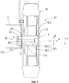
- FIG. 1 shows part of an exemplary embodiment of a travelling device D according to the invention, which for example could be a heavy-load vehicle or a movable pressure washer, especially a professional high-pressure washer.
- the travelling device comprises a frame F, at least one wheel mounting assembly M and at least one wheel assembly W.
- the wheel assembly W is particularly used as an idle wheel.
- the wheel mounting assembly M comprises an axle 1 and an adapter 2.
- the adapter 2 is fixed on the frame F.
- the axle 1 is installed on the adapter 2 in a manner of not relatively rotate with each other in the circumferential direction C.
- the wheel assembly W is installed on the axle 1, and the wheel can rotate relatively to the axle 1.
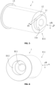
- the adapter 2 has a cylinder shape. In the axial direction A, define one end of the adapter 2 that facing the axle 1 as the adapter mounting end E21.
- the central part of the adapter 2 is concave to form a second match part 21.
- the outer part of the second match part 21 forms an outer rim 22.
- the second match part 21 is a blind hole with a slotted shape, which could match with a first match part 11 of the axle 1 to be introduced in the following description.
- the inner part of the adapter 2 forms an adapter hole H2.
- the adapter hole H2 is a screw hole, and it goes through the solid part of the adapter 2.
- the adapter 2 comprises a first part 2a and a second part 2b connecting with each other.
- the outer diameter of the first part 2a is larger than the outer diameter of the second part 2b.
- the surface between the first part 2a and the second part 2b forms a shoulder 2c.
- the shoulder 2c attributes to position the adapter 2 on the frame F.
- the frame F comprises a mounting hole F1.
- the inner diameter of the mounting hole F1 is approximately the same with the outer diameter of the second part 2b of the adapter 2, and the inner diameter of the mounting hole F1 is smaller than the outer diameter of the first part 2a of the adapter 2. So, the adapter 2 could be inserted in the mounting hole F1 with the second part 2b touching the inner surface of the mounting hole F1 and the shoulder 2c in contacting with the side wall of the frame F.
- the adapter 2 could further be welded on the frame. It should be noted that, in other embodiments, the adapter 2 could also be fixed on the frame F in other ways, for example by using some other fasteners.
- the adapter hole H2 could be a blind hole with an opening end facing the axle 1.
- the axle 1 has a cylinder shape. In the axial direction A, define one end of the axle 1 that facing the adapter 2 as the axle mounting end E11.
- the central part of the axle 1 is convex to form a first match part 11.
- the outer part of the first match part 11 forms an outer rim of axle 12.
- the first match part 11 has the same shape with the second match part 21, or in more precise words, when using a flat surface perpendicular to the axial direction to cut the first match part 11 and the second match part 21, the outline of the first match part 11 is approximately the same as the second match part 21. So, the first match part 11 and the second match part 21 can connect with each other in a form-locked manner to transmit torque.
- height d1 of the first match part 11 is shorter than the depth d2 (refer to FIG. 2 as well) of the second match part 21. So, in an assembled situation, there will be a gap G between the top of the first match part 11 and the bottom of the second match part 21. This ensures that when the axle 1 is assembled with the adapter 2, the outer rim 22 will be in contact with the outer rim of axle 12, to transfer a maximum torque between the axle 1 and the adapter 2.
- axle hole H1 The inner part of the axle 1 forms an axle hole H1.
- the axle hole H1 is an unthreaded hole, and it goes through the axle 1.
- the axle hole H1 comprises a first hole part H11 and a second hole part H12 connecting with each other in the axial direction A.
- the inner diameter of the second hole part H12 is larger than the inner diameter of the first hole part H11.
- the inner diameter of the first hole part H11 is a little bit larger than the inner diameter of the adapter hole H2.
- axle hole H1 could be of the same diameter in different axial position, which means the second hole part H12 is not necessary. And in situation without a second hole part H12, the screw head could be set out of the axle hole H1.
- the connecting structure of the first match part 11 and the second match part 21. could avoid the bolt from getting unscrewed. Even during the rotating movement of the wheel assembly W, the wheel hub W1 will transmit torque to the axle 1, the axle 1 will not rotate relative to the adapter 2, so the bolt is hardly rotating relative to the axle 1 or the adapter 2.
- the other end of the axle 1 facing away from the adapter 2 forms a flange 13.
- the flange 13 is in contact with the wheel hub W1 of the wheel assembly W.
- Fig. 7 shows a second embodiment of the axle 1 according to this invention.
- the diameter of the main body (where the wheel assembly is installed) of axle 1 is smaller, this makes the first match part 11 having almost the same diameter as the main body, and the outer rim of axle 12 could comprise two separate areas (not a circular area).
- the area of outer rim of axle 12 would be pretty small, so it is preferably that the end face 11e of the first match part 11 being in touch with the end face 21e of the second match part 21, or in other words, there will be no gap G (refer to Fig. 1 ) in this situation.
- Figs. 6-8 shows a third embodiment of the axle 1 according to this invention.
- the diameter of the main body of the axle 1 is smaller than the diameter of the first match part 11, and the axle 1 comprises a main part 1a and a washer part 1b.
- the wheel assembly W will be installed on the axle 1 from the flange end E12.
- the outer rim of axle 12 as showed in the first embodiment no longer exists. So, the height d1 of the first match part 11 could be shorter than, or equals to, or even longer than or the depth d2 of the second match part 12 (refer to FIG. 2 ), while it is preferable that the two parts are approximately at the same length. In any of the options that the height d1 and the depth d2 be chosen, the end face 11e of the first match part 11 would be in touch with the end face 21e of the second match part 21, or in other words, there would be no gap G (refer to Fig. 1 ) in this situation.
- the washer part 1b could be fixed on the main part 1a by the above-mentioned fastener, so that after installation, the wheel assembly could be positioned in the axial direction A.
- the main part 1a forms a first positioning part 14, while the washer part 1b forms a second positioning part 15.
- the first positioning part 14 matches with the second positioning part 15, so that the washer part 1b could not rotate relatively to the main part 1a.
- the first positioning part 14 is a slot
- the second positioning part 15 is a protrusion that could be inserted into the slot.
- the washer part 1b further comprises a rim 16.
- the rim 16 will be inserted in the axle hole H1, and the outer surface of the rim 16 touches the surface of the axle hole H1.
Landscapes
- Engineering & Computer Science (AREA)
- Mechanical Engineering (AREA)
- Automatic Assembly (AREA)
Priority Applications (1)
| Application Number | Priority Date | Filing Date | Title |
|---|---|---|---|
| EP22184115.8A EP4306332A1 (de) | 2022-07-11 | 2022-07-11 | Radmontageanordnung und fahrbare vorrichtung |
Applications Claiming Priority (1)
| Application Number | Priority Date | Filing Date | Title |
|---|---|---|---|
| EP22184115.8A EP4306332A1 (de) | 2022-07-11 | 2022-07-11 | Radmontageanordnung und fahrbare vorrichtung |
Publications (1)
| Publication Number | Publication Date |
|---|---|
| EP4306332A1 true EP4306332A1 (de) | 2024-01-17 |
Family
ID=82403653
Family Applications (1)
| Application Number | Title | Priority Date | Filing Date |
|---|---|---|---|
| EP22184115.8A Pending EP4306332A1 (de) | 2022-07-11 | 2022-07-11 | Radmontageanordnung und fahrbare vorrichtung |
Country Status (1)
| Country | Link |
|---|---|
| EP (1) | EP4306332A1 (de) |
Citations (4)
| Publication number | Priority date | Publication date | Assignee | Title |
|---|---|---|---|---|
| DE29604243U1 (de) * | 1996-03-07 | 1996-05-09 | Masters CY Industrial Co., Ltd., Tu Cheng Hsiang, Taipeh | Radmontageaufbau eines Golfwagens |
| US5887952A (en) * | 1993-08-18 | 1999-03-30 | Toora S.R.L. | Light alloy wheel assembly for an automobile |
| DE102018007072A1 (de) * | 2018-09-07 | 2020-03-12 | Scc Fahrzeugtechnik Gmbh | Zentralverschlusssystem mit Felge |
| KR102240074B1 (ko) * | 2020-08-11 | 2021-04-14 | 민상규 | 피 견인차량용 차축장치 |
-
2022
- 2022-07-11 EP EP22184115.8A patent/EP4306332A1/de active Pending
Patent Citations (4)
| Publication number | Priority date | Publication date | Assignee | Title |
|---|---|---|---|---|
| US5887952A (en) * | 1993-08-18 | 1999-03-30 | Toora S.R.L. | Light alloy wheel assembly for an automobile |
| DE29604243U1 (de) * | 1996-03-07 | 1996-05-09 | Masters CY Industrial Co., Ltd., Tu Cheng Hsiang, Taipeh | Radmontageaufbau eines Golfwagens |
| DE102018007072A1 (de) * | 2018-09-07 | 2020-03-12 | Scc Fahrzeugtechnik Gmbh | Zentralverschlusssystem mit Felge |
| KR102240074B1 (ko) * | 2020-08-11 | 2021-04-14 | 민상규 | 피 견인차량용 차축장치 |
Similar Documents
| Publication | Publication Date | Title |
|---|---|---|
| JP3781057B2 (ja) | リベッティング可能な要素、組立体、組立方法及びリベッティングダイ | |
| EP0066794A1 (de) | Befestigungsmittel und Methode zur Herstellung | |
| JP4921504B2 (ja) | ディスクロータ案内装置及び外径案内装置 | |
| US8353659B2 (en) | Fastening method for a fastening bolt of a sub frame to car body and a sub frame rigid collar for car used for the fastening method | |
| JPS6149528B2 (de) | ||
| CN113606242A (zh) | 一种防转螺母组件、转向器安装结构及安装方法 | |
| US11498193B2 (en) | Wheel hub bearing extraction tool | |
| US20080296965A1 (en) | Wheel Hub Comprising Axial Recesses Formed Between the Holes for Wheel Nuts | |
| US6406237B1 (en) | Method of attaching a fastener element to a panel and fastener element and panel assembly | |
| JP2011519325A (ja) | ハブ・ブレーキローター・アセンブリ | |
| EP2052877A1 (de) | Spannungsreduzierungssystem für Radnaben | |
| EP2735747B1 (de) | Drehverhinderungsstruktur für muttern | |
| JP2008537065A (ja) | 自動装着ファスナ並びにファスナとパネルの組立部材 | |
| US4982998A (en) | Two piece construction wheel for an automobile | |
| TW202246662A (zh) | 具多用途先導的自鎖式和自刺式結構元件 | |
| CN103352924A (zh) | 一种重载轮毂圆锥过盈联结结构及其装拆方法 | |
| US20070157444A1 (en) | Stud installation tool and method of stud installation | |
| US7631948B2 (en) | Wheel hub comprising axial recesses formed between the holes for wheel nuts | |
| JP4326191B2 (ja) | ピン型保持器 | |
| US20070253770A1 (en) | Joined connection, joining element and method for inserting a joining element into a component | |
| CN217152524U (zh) | 一种连接结构及发动机 | |
| CN109848917B (zh) | 一种组件与轴承分解工具 | |
| CN208559489U (zh) | 一种自动驾驶方向盘传动机构及地面车辆 | |
| JP2876383B2 (ja) | 組立式自動車ホイール | |
| CN217198094U (zh) | 一种安装小直径轮毂的碟刹后桥结构 |
Legal Events
| Date | Code | Title | Description |
|---|---|---|---|
| PUAI | Public reference made under article 153(3) epc to a published international application that has entered the european phase |
Free format text: ORIGINAL CODE: 0009012 |
|
| STAA | Information on the status of an ep patent application or granted ep patent |
Free format text: STATUS: THE APPLICATION HAS BEEN PUBLISHED |
|
| AK | Designated contracting states |
Kind code of ref document: A1 Designated state(s): AL AT BE BG CH CY CZ DE DK EE ES FI FR GB GR HR HU IE IS IT LI LT LU LV MC MK MT NL NO PL PT RO RS SE SI SK SM TR |
|
| STAA | Information on the status of an ep patent application or granted ep patent |
Free format text: STATUS: REQUEST FOR EXAMINATION WAS MADE |
|
| 17P | Request for examination filed |
Effective date: 20240717 |
|
| RBV | Designated contracting states (corrected) |
Designated state(s): AL AT BE BG CH CY CZ DE DK EE ES FI FR GB GR HR HU IE IS IT LI LT LU LV MC MK MT NL NO PL PT RO RS SE SI SK SM TR |