EP4306362A1 - Système d'éclairage de véhicule automobile - Google Patents
Système d'éclairage de véhicule automobile Download PDFInfo
- Publication number
- EP4306362A1 EP4306362A1 EP22185213.0A EP22185213A EP4306362A1 EP 4306362 A1 EP4306362 A1 EP 4306362A1 EP 22185213 A EP22185213 A EP 22185213A EP 4306362 A1 EP4306362 A1 EP 4306362A1
- Authority
- EP
- European Patent Office
- Prior art keywords
- motor vehicle
- area
- light
- signlight
- adaptive
- Prior art date
- Legal status (The legal status is an assumption and is not a legal conclusion. Google has not performed a legal analysis and makes no representation as to the accuracy of the status listed.)
- Granted
Links
Images


Classifications
-
- B—PERFORMING OPERATIONS; TRANSPORTING
- B60—VEHICLES IN GENERAL
- B60Q—ARRANGEMENT OF SIGNALLING OR LIGHTING DEVICES, THE MOUNTING OR SUPPORTING THEREOF OR CIRCUITS THEREFOR, FOR VEHICLES IN GENERAL
- B60Q1/00—Arrangement of optical signalling or lighting devices, the mounting or supporting thereof or circuits therefor
- B60Q1/02—Arrangement of optical signalling or lighting devices, the mounting or supporting thereof or circuits therefor the devices being primarily intended to illuminate the way ahead or to illuminate other areas of way or environments
- B60Q1/04—Arrangement of optical signalling or lighting devices, the mounting or supporting thereof or circuits therefor the devices being primarily intended to illuminate the way ahead or to illuminate other areas of way or environments the devices being headlights
- B60Q1/06—Arrangement of optical signalling or lighting devices, the mounting or supporting thereof or circuits therefor the devices being primarily intended to illuminate the way ahead or to illuminate other areas of way or environments the devices being headlights adjustable, e.g. remotely-controlled from inside vehicle
- B60Q1/08—Arrangement of optical signalling or lighting devices, the mounting or supporting thereof or circuits therefor the devices being primarily intended to illuminate the way ahead or to illuminate other areas of way or environments the devices being headlights adjustable, e.g. remotely-controlled from inside vehicle automatically
-
- B—PERFORMING OPERATIONS; TRANSPORTING
- B60—VEHICLES IN GENERAL
- B60Q—ARRANGEMENT OF SIGNALLING OR LIGHTING DEVICES, THE MOUNTING OR SUPPORTING THEREOF OR CIRCUITS THEREFOR, FOR VEHICLES IN GENERAL
- B60Q1/00—Arrangement of optical signalling or lighting devices, the mounting or supporting thereof or circuits therefor
- B60Q1/02—Arrangement of optical signalling or lighting devices, the mounting or supporting thereof or circuits therefor the devices being primarily intended to illuminate the way ahead or to illuminate other areas of way or environments
- B60Q1/04—Arrangement of optical signalling or lighting devices, the mounting or supporting thereof or circuits therefor the devices being primarily intended to illuminate the way ahead or to illuminate other areas of way or environments the devices being headlights
- B60Q1/14—Arrangement of optical signalling or lighting devices, the mounting or supporting thereof or circuits therefor the devices being primarily intended to illuminate the way ahead or to illuminate other areas of way or environments the devices being headlights having dimming means
- B60Q1/1415—Dimming circuits
- B60Q1/1423—Automatic dimming circuits, i.e. switching between high beam and low beam due to change of ambient light or light level in road traffic
- B60Q1/143—Automatic dimming circuits, i.e. switching between high beam and low beam due to change of ambient light or light level in road traffic combined with another condition, e.g. using vehicle recognition from camera images or activation of wipers
-
- B—PERFORMING OPERATIONS; TRANSPORTING
- B60—VEHICLES IN GENERAL
- B60Q—ARRANGEMENT OF SIGNALLING OR LIGHTING DEVICES, THE MOUNTING OR SUPPORTING THEREOF OR CIRCUITS THEREFOR, FOR VEHICLES IN GENERAL
- B60Q1/00—Arrangement of optical signalling or lighting devices, the mounting or supporting thereof or circuits therefor
- B60Q1/02—Arrangement of optical signalling or lighting devices, the mounting or supporting thereof or circuits therefor the devices being primarily intended to illuminate the way ahead or to illuminate other areas of way or environments
- B60Q1/04—Arrangement of optical signalling or lighting devices, the mounting or supporting thereof or circuits therefor the devices being primarily intended to illuminate the way ahead or to illuminate other areas of way or environments the devices being headlights
- B60Q1/06—Arrangement of optical signalling or lighting devices, the mounting or supporting thereof or circuits therefor the devices being primarily intended to illuminate the way ahead or to illuminate other areas of way or environments the devices being headlights adjustable, e.g. remotely-controlled from inside vehicle
- B60Q1/08—Arrangement of optical signalling or lighting devices, the mounting or supporting thereof or circuits therefor the devices being primarily intended to illuminate the way ahead or to illuminate other areas of way or environments the devices being headlights adjustable, e.g. remotely-controlled from inside vehicle automatically
- B60Q1/085—Arrangement of optical signalling or lighting devices, the mounting or supporting thereof or circuits therefor the devices being primarily intended to illuminate the way ahead or to illuminate other areas of way or environments the devices being headlights adjustable, e.g. remotely-controlled from inside vehicle automatically due to special conditions, e.g. adverse weather, type of road, badly illuminated road signs or potential dangers
-
- B—PERFORMING OPERATIONS; TRANSPORTING
- B60—VEHICLES IN GENERAL
- B60Q—ARRANGEMENT OF SIGNALLING OR LIGHTING DEVICES, THE MOUNTING OR SUPPORTING THEREOF OR CIRCUITS THEREFOR, FOR VEHICLES IN GENERAL
- B60Q1/00—Arrangement of optical signalling or lighting devices, the mounting or supporting thereof or circuits therefor
- B60Q1/0029—Spatial arrangement
- B60Q1/0041—Spatial arrangement of several lamps in relation to each other
- B60Q1/0047—Signalling unit mounted on a headlamp unit
-
- B—PERFORMING OPERATIONS; TRANSPORTING
- B60—VEHICLES IN GENERAL
- B60Q—ARRANGEMENT OF SIGNALLING OR LIGHTING DEVICES, THE MOUNTING OR SUPPORTING THEREOF OR CIRCUITS THEREFOR, FOR VEHICLES IN GENERAL
- B60Q1/00—Arrangement of optical signalling or lighting devices, the mounting or supporting thereof or circuits therefor
- B60Q1/02—Arrangement of optical signalling or lighting devices, the mounting or supporting thereof or circuits therefor the devices being primarily intended to illuminate the way ahead or to illuminate other areas of way or environments
- B60Q1/04—Arrangement of optical signalling or lighting devices, the mounting or supporting thereof or circuits therefor the devices being primarily intended to illuminate the way ahead or to illuminate other areas of way or environments the devices being headlights
- B60Q1/14—Arrangement of optical signalling or lighting devices, the mounting or supporting thereof or circuits therefor the devices being primarily intended to illuminate the way ahead or to illuminate other areas of way or environments the devices being headlights having dimming means
-
- B—PERFORMING OPERATIONS; TRANSPORTING
- B60—VEHICLES IN GENERAL
- B60R—VEHICLES, VEHICLE FITTINGS, OR VEHICLE PARTS, NOT OTHERWISE PROVIDED FOR
- B60R1/00—Optical viewing arrangements; Real-time viewing arrangements for drivers or passengers using optical image capturing systems, e.g. cameras or video systems specially adapted for use in or on vehicles
- B60R1/20—Real-time viewing arrangements for drivers or passengers using optical image capturing systems, e.g. cameras or video systems specially adapted for use in or on vehicles
- B60R1/22—Real-time viewing arrangements for drivers or passengers using optical image capturing systems, e.g. cameras or video systems specially adapted for use in or on vehicles for viewing an area outside the vehicle, e.g. the exterior of the vehicle
-
- G—PHYSICS
- G06—COMPUTING OR CALCULATING; COUNTING
- G06V—IMAGE OR VIDEO RECOGNITION OR UNDERSTANDING
- G06V20/00—Scenes; Scene-specific elements
- G06V20/50—Context or environment of the image
- G06V20/56—Context or environment of the image exterior to a vehicle by using sensors mounted on the vehicle
- G06V20/58—Recognition of moving objects or obstacles, e.g. vehicles or pedestrians; Recognition of traffic objects, e.g. traffic signs, traffic lights or roads
- G06V20/582—Recognition of moving objects or obstacles, e.g. vehicles or pedestrians; Recognition of traffic objects, e.g. traffic signs, traffic lights or roads of traffic signs
-
- H—ELECTRICITY
- H05—ELECTRIC TECHNIQUES NOT OTHERWISE PROVIDED FOR
- H05B—ELECTRIC HEATING; ELECTRIC LIGHT SOURCES NOT OTHERWISE PROVIDED FOR; CIRCUIT ARRANGEMENTS FOR ELECTRIC LIGHT SOURCES, IN GENERAL
- H05B45/00—Circuit arrangements for operating light-emitting diodes [LED]
- H05B45/30—Driver circuits
- H05B45/32—Pulse-control circuits
- H05B45/325—Pulse-width modulation [PWM]
-
- B—PERFORMING OPERATIONS; TRANSPORTING
- B60—VEHICLES IN GENERAL
- B60Q—ARRANGEMENT OF SIGNALLING OR LIGHTING DEVICES, THE MOUNTING OR SUPPORTING THEREOF OR CIRCUITS THEREFOR, FOR VEHICLES IN GENERAL
- B60Q2300/00—Indexing codes for automatically adjustable headlamps or automatically dimmable headlamps
- B60Q2300/05—Special features for controlling or switching of the light beam
- B60Q2300/054—Variable non-standard intensity, i.e. emission of various beam intensities different from standard intensities, e.g. continuous or stepped transitions of intensity
-
- B—PERFORMING OPERATIONS; TRANSPORTING
- B60—VEHICLES IN GENERAL
- B60Q—ARRANGEMENT OF SIGNALLING OR LIGHTING DEVICES, THE MOUNTING OR SUPPORTING THEREOF OR CIRCUITS THEREFOR, FOR VEHICLES IN GENERAL
- B60Q2300/00—Indexing codes for automatically adjustable headlamps or automatically dimmable headlamps
- B60Q2300/40—Indexing codes relating to other road users or special conditions
- B60Q2300/42—Indexing codes relating to other road users or special conditions oncoming vehicle
-
- B—PERFORMING OPERATIONS; TRANSPORTING
- B60—VEHICLES IN GENERAL
- B60Q—ARRANGEMENT OF SIGNALLING OR LIGHTING DEVICES, THE MOUNTING OR SUPPORTING THEREOF OR CIRCUITS THEREFOR, FOR VEHICLES IN GENERAL
- B60Q2300/00—Indexing codes for automatically adjustable headlamps or automatically dimmable headlamps
- B60Q2300/40—Indexing codes relating to other road users or special conditions
- B60Q2300/45—Special conditions, e.g. pedestrians, road signs or potential dangers
-
- B—PERFORMING OPERATIONS; TRANSPORTING
- B60—VEHICLES IN GENERAL
- B60Q—ARRANGEMENT OF SIGNALLING OR LIGHTING DEVICES, THE MOUNTING OR SUPPORTING THEREOF OR CIRCUITS THEREFOR, FOR VEHICLES IN GENERAL
- B60Q2400/00—Special features or arrangements of exterior signal lamps for vehicles
- B60Q2400/30—Daytime running lights [DRL], e.g. circuits or arrangements therefor
Definitions
- the invention relates to a motor vehicle lighting system comprising at least two adaptive motor vehicle headlights, an adaptive motor vehicle headlight being a headlight which is set up to generate a low beam distribution and an adaptive high beam distribution with a resolution of at least two, preferably at least seven, individually controllable segments, the low beam distribution being one for the area assigned to the traffic sign lighting, hereinafter referred to as the signlight area, which at least partially overlaps with an emission area that is assigned to the high beam distribution, has at least one camera system for detecting the surroundings of the motor vehicle lighting system and for outputting corresponding surroundings data, in that the camera system is used for detection and relative Position determination of road users measured in relation to the at least two adaptive motor vehicle headlights is set up, at least one control unit which is connected to the camera system for receiving the surrounding data and to the at least two adaptive motor vehicle headlights for controlling the adaptive motor vehicle headlights, the control unit being set up to do so Surrounding data by comparing a recorded relative position of a road user with a first position area that can be illuminate
- the light distributions of adjacent segments overlap one another at least partially to enable homogeneous illumination and to evenly illuminate transitions between the individual segments. This means that in practice, despite the segments in question being switched off individually, a residual amount of light is still emitted into the area to be blocked out by the high beam module.
- One object of the invention is to further reduce the likelihood of possible blinding of road users.
- control unit is further set up to carry out a comparison of its detected relative position with a second position area, which can be illuminated by the signlight area, in the presence of a road user to be hidden, and thereby to infer the presence of road users to be hidden within the second position range
- each adaptive motor vehicle headlight being further provided with a control means, each control means being set up to control the intensity of the illumination of the signlight area by the respective adaptive motor vehicle headlight deviating from the intensities of the remaining areas to regulate the low beam distribution, for this purpose the control unit is connected to the control means and the control means is controlled in such a way that if the presence of a road user to be hidden within the second position range is detected, the intensity of the light emitted into the signlight area is also compared to one condition, in in which no road user to be hidden is detected within the second position range.
- the invention makes it possible to create a lighting system that takes into account the superimposition of the radiation from all light sources active in a vehicle. More precisely, for example, in glare-free high beam operation, not only the radiation from the high beam module, but from all light modules that contribute to the radiation in the glare-relevant area, in particular in the so-called signlight area, which is intended for illuminating traffic signs and signs, can be monitored.
- the camera system can include, for example, an optical camera.
- the signlight area is also referred to as ZoneIII in the ECE_R149 regulation, for example. It can also be described as an area that is at least partially above the Patoscuro limit of a low beam distribution and is intended to illuminate traffic signs. In the US FMVSS No108 standard already mentioned, the term “OHS” is also used for this purpose.
- the segments are typically arranged in at least one horizontal row, but two or more rows can also be provided, the segments being arranged next to each other in a matrix-like manner, or one above the other in multi-row versions, and a row can have at least seven columns, for example.
- a horizontal resolution with at least 10 light segments can be useful, and this resolution can be achieved, for example, by superimposing the radiation of the individual segments of the left and right headlights.
- a left and a right headlight can each have, for example, seven individual segments that overlap mirror-asymmetrically and result in a total of, for example, 11 segments.
- High-resolution systems can have a large number of segments, allowing resolutions ⁇ 0.1° (horizontal).
- the reduction in the intensity of the light emitted into the signlight area is at least 30% compared to a state in which no road user to be hidden is detected within the signlight area.
- the reduction can be, for example, 50% or more.
- control means is designed as a current regulator of the light source that is responsible for emitting the signlight area.
- control means is designed in the form of a PWM dimming that is assigned to the light source that is responsible for emitting the signlight area.
- control means is designed as an adaptive light filter, the light transmission of which can be variably controlled, which is arranged, preferably exclusively, in the light path of the optical component that is intended for emission into the signlight area.
- the control means can be set up to absorb the light passing through the adaptive light filter depending on the surrounding data.
- each adaptive headlight which is set up exclusively for emission into the signlight area.
- Such a module can also be referred to as a “standalone” module.
- the signlight can also be implemented using a bi-functional reflector concept, for example by means of a paraboloid reflector, whereby the light source, in particular an LED light source, for the low beam light distribution (with the exception of the signlight portion) sits in the focus of the reflector and away from the focus point
- the light source in particular an LED light source
- An additional light source is provided specifically for Signlight and is positioned accordingly and can be controlled individually.
- the signlight radiation itself is segmented and in turn only areas of the signlight radiation that are relevant to glare are deactivated.
- a segmented filter and/or an arrangement can be used for this purpose comprising two or more light sources.
- an additional light source in particular an LED light source, is controlled using a matrix controller: Similar to before, only that certain light sources of a pixel light module are responsible for the signlight and these are controlled individually in the usual way.
- a signal light device is provided for emission into the sign light area, the signal light device preferably being a daytime running light module, a parking light module, a position light module, a boundary light module, an ambient light module and / or a design light module, each signal light device one control means is assigned to each.
- Signal light devices are understood to mean all light modules that are intended to increase visibility for third parties by emitting light.
- a control means in particular one control means each, is assigned to all light sources and/or light modules of the motor vehicle lighting system provided for emitting light, which are at least partially set up to emit light into the signlight area.
- the invention further relates to a motor vehicle comprising a motor vehicle lighting system according to the invention.
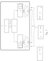
- FIG. 1 shows a schematic representation of a motor vehicle lighting system 1 according to the invention.
- the motor vehicle lighting system 1 comprises at least two adaptive motor vehicle headlights 2.
- An adaptive motor vehicle headlight 2 is a headlight that is used to generate a low beam distribution AL (see Fig. 2 ) and an adaptive high beam distribution FL (see Fig. 2 ) with a resolution of at least two, preferably at least seven, individually controllable segments FLs1, FLs2, FLs13 (see Fig. 4 ) is set up, whereby the low beam distribution AL has an area assigned to the traffic sign lighting, hereinafter referred to as the signlight area ALsl (see Fig. 2 ) called, which at least partially overlaps with a radiation area that is assigned to the high beam distribution FL.
- ALsl the signlight area
- the motor vehicle lighting system 1 has at least one camera system 3 for detecting the surroundings of the motor vehicle lighting system 1 and for outputting surrounding data D corresponding thereto.
- the environment is detected by the camera system 3 being set up to detect and determine the relative position Pos1, Pos2, Pos3 of road users 4, 4', 4" measured in relation to the at least two adaptive motor vehicle headlights 2.
- the motor vehicle lighting system 1 has at least one control unit 5, which is connected to the camera system 3 for receiving the surroundings data D and to the at least two adaptive motor vehicle headlights 2 for controlling the adaptive motor vehicle headlights 2, the control unit 5 being set up to transmit the surroundings data D
- the road user 4 is located according to position Pos 1 outside the first position range 2 ' (e.g. far to the side of the light-emitting system 1) and therefore does not have to be hidden - typically because the normal high beam distribution does not cause any glare in this constellation.
- Another road user 4' lies within the first position range 2' according to position Pos 2 and must therefore be hidden.
- a third road user 4" is also located within the first position area 2' according to Pos. 3 and must therefore be hidden.
- the control unit 5 is furthermore set up to compare the detected relative position Pos with a road user 4' and 4" to be hidden if there is a road user 4' and 4" to be hidden second position area 2", which can be illuminated by the signlight area ALsl, and thereby draw conclusions about the presence of road users 4 to be hidden within the second position area 2".
- Each adaptive motor vehicle headlight 2 is further provided with a control means 2a, each control means 2a being set up to regulate the intensity of the illumination of the signlight area ALsl by the respective adaptive motor vehicle headlight 2 deviating from the intensities of the remaining areas of the low beam distribution AL.
- control unit 5 is connected to the control means 2a and the control means 2a is controlled in such a way that if the presence of a road user 4" to be hidden within the second position area 2" is detected, the intensity of the light emitted into the signlight area ALsl is also compared is reduced to a state in which no road user 4 to be masked out is detected within the second position range 2", that is, an otherwise provided light intensity I1 is reduced to a lower light intensity I2.
- the light intensities I1 and I2 describe an absolute light intensity, which is determined by superimposition of the total amount of light emitted by light sources into the signlight area. In the case of the masking described, this is reduced from I1 to I2.
- the reduction in the intensity I2 of the light emitted into the signlight area ALsl compared to a state in which no road user 4 to be hidden is detected within the signlight area ALsl I1 is at least 30%, but can also be at least 50%, 80% or even 100%.
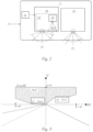
- Figure 2 shows a schematic representation of an adaptive motor vehicle headlight 2.
- This includes a light module 2b, which is set up to emit the low beam light distribution AL, which can also have a light source 2b ', which is exclusively responsible for emitting into a signlight area ALsl.
- an additional light module 2c can be provided that is intended exclusively for emitting the segmented high beam distribution FL, which is designed to be adaptive.
- Figure 3 shows a schematic representation of a signlight light distribution in the vicinity of road users 4, namely the one previously shown in Fig. 1 shown road users 4 'and 4".
- the road user 4" at Pos3 is within the signlight distribution, which is also referred to as Zone III, and represents the second position range 2", and the road user 4' at Pos2, however, lies outside the second position range 2".
- Figure 4 shows a schematic representation of individual controllable segments FLs1, FLs2, FLs13 of an adaptive high beam distribution FL.
- the segments were shown and labeled as examples. Their number, arrangement and size can vary depending on the application. They can also have different widths w1 and w2, both in the horizontal and vertical directions.
- Figure 5 shows schematically a masking scenario with the lanes 10' (left) and 10" (right), whereby the Pos3 of an oncoming road user 4" is hidden by deactivating the light segments FLs5 and FLs6 and this road user 4" does not experience any glare.
- This area in Traffic area is considered an “area of reduced intensity” ( Fig.6 ), within which the specifications for minimum and maximum light intensities of a low beam distribution, e.g. "lower beam pattern" LB2V according to Federal Motor Vehicle Safety Standards 108 in the USA, can be reliably met by the invention.
- Figure 6 describes for a specific driving situation (oncoming vehicle at a distance of 30 m) the “area of reduced intensity” 11 in a rectangle with the horizontal extent of 7.0°L to 2.0°L and the vertical extent of 0.4°D up to 3.0°U.
- ALsl-No1 [2°U,4°L]
- a maximum light intensity of 1000cd should not be exceeded along the horizontal measuring line ALsl-L1 at 0.5°U or a maximum light intensity of 700cd along the horizontal measuring line ALsl-L2 at 1.0°U.
- Transition zones 12a and 12b Adjacent to this are “transition zones” 12a and 12b, each of which should have an extent of ⁇ 1.0° and in which the maximum light intensity should be 75,000 cd. Outside this zone lies the area of "area of unreduced intensity" 13, in which the specifications for high beam distribution, for example "upper beam pattern" UB2 according to Federal Motor Vehicle Safety Standards 108 in the USA, are reliable should be adhered to.
- light intensities >40000cd and ⁇ 75000cd are prescribed in the HV measuring point, and more than 3000cd in the FL-No1 [H,9°L] measuring point.
- the overlapping areas of the signlight area ALsl and the area of reduced intensity should also be taken into account.
- Fig. 2 It is also shown by way of example that at least one light source 2b' is provided for each adaptive headlight 2, which is set up exclusively for emission into the signlight area ALsl.
- a signal light device 2d is provided for emission into the signlight area ALsl, the signal light device preferably being a daytime running light module, a parking light module, a position light module, a boundary light module, an ambient light module and / or a design light module, whereby Each signal light device 2d is assigned a control means 2a.
- a control means 2a is assigned to all light sources and/or light modules of the motor vehicle lighting system 1 intended for emitting light, which are at least partially set up to emit light into the signlight area Als1.
- Figure 7a shows a schematic representation of a first type of control of the intensity of the signlight radiation, in which the control means 2a is designed as a current regulator 2a 'of that light source 2b' of the signlight headlight 2b, which is responsible for the radiation of the signlight area ALsl. It can also be provided that the control means 2a is designed in the form of a PWM dimming, which is assigned to that light source 2b ', which is responsible for the emission of the signlight area ALsl.
- Figure 7b a schematic representation of a second type of control of the intensity of the signlight radiation, in which the control means 2a is designed as an adaptive light filter 2a ", the light transmission of which can be variably controlled, which is arranged, preferably exclusively, in the light path of that optical component 2b ', which is intended for emission into the signlight area ALsl.
- the control means 2a is designed as an adaptive light filter 2a ", the light transmission of which can be variably controlled, which is arranged, preferably exclusively, in the light path of that optical component 2b ', which is intended for emission into the signlight area ALsl.
- Figure 8 shows a schematic representation of a motor vehicle 6 comprising a motor vehicle lighting system 1 according to the invention.
Landscapes
- Engineering & Computer Science (AREA)
- Mechanical Engineering (AREA)
- Multimedia (AREA)
- Physics & Mathematics (AREA)
- General Physics & Mathematics (AREA)
- Theoretical Computer Science (AREA)
- Lighting Device Outwards From Vehicle And Optical Signal (AREA)
Priority Applications (3)
| Application Number | Priority Date | Filing Date | Title |
|---|---|---|---|
| EP22185213.0A EP4306362B1 (fr) | 2022-07-15 | 2022-07-15 | Système d'éclairage de véhicule automobile |
| CN202310653605.XA CN117400819A (zh) | 2022-07-15 | 2023-06-02 | 机动车辆灯光系统 |
| US18/214,868 US12351100B2 (en) | 2022-07-15 | 2023-06-27 | Motor vehicle lighting system |
Applications Claiming Priority (1)
| Application Number | Priority Date | Filing Date | Title |
|---|---|---|---|
| EP22185213.0A EP4306362B1 (fr) | 2022-07-15 | 2022-07-15 | Système d'éclairage de véhicule automobile |
Publications (2)
| Publication Number | Publication Date |
|---|---|
| EP4306362A1 true EP4306362A1 (fr) | 2024-01-17 |
| EP4306362B1 EP4306362B1 (fr) | 2025-10-15 |
Family
ID=82608347
Family Applications (1)
| Application Number | Title | Priority Date | Filing Date |
|---|---|---|---|
| EP22185213.0A Active EP4306362B1 (fr) | 2022-07-15 | 2022-07-15 | Système d'éclairage de véhicule automobile |
Country Status (3)
| Country | Link |
|---|---|
| US (1) | US12351100B2 (fr) |
| EP (1) | EP4306362B1 (fr) |
| CN (1) | CN117400819A (fr) |
Citations (5)
| Publication number | Priority date | Publication date | Assignee | Title |
|---|---|---|---|---|
| WO2002004247A1 (fr) * | 2000-07-09 | 2002-01-17 | 3Dv Systems, Ltd. | Procede et dispositif d'eclairage adaptatif |
| EP2085688A2 (fr) * | 2008-01-29 | 2009-08-05 | Koito Manufacturing Co., Ltd. | Appareil de phare d'automobile et procédé de commande |
| US20140071702A1 (en) * | 2011-03-02 | 2014-03-13 | Petko Faber | Method and control unit for influencing a lighting scene ahead of a vehicle |
| DE102015008729A1 (de) * | 2015-07-07 | 2017-01-12 | GM Global Technology Operations LLC (n. d. Ges. d. Staates Delaware) | Kraftfahrzeugscheinwerferanordnung, Kraftfahrzeugscheinwerfersystem, Kraftfahrzeug sowie Verfahren zum Betrieb eines Kraftfahrzeugs |
| DE102020126935A1 (de) * | 2020-10-14 | 2022-04-14 | Dr. Ing. H.C. F. Porsche Aktiengesellschaft | Verfahren zum Ansteuern eines Scheinwerfers eines Fahrzeugs mit Beleuchtungsfunktion von Überkopf-Straßenschildern und entsprechend konfigurierter Scheinwerfer |
Family Cites Families (5)
| Publication number | Priority date | Publication date | Assignee | Title |
|---|---|---|---|---|
| US7195379B2 (en) * | 2005-01-03 | 2007-03-27 | Ford Global Technologies, Llc | Anti-blinding system for a vehicle |
| DE102013001086A1 (de) * | 2013-01-23 | 2014-07-24 | Audi Ag | Kraftfahrzeug, umfassend mehrere der Beleuchtung des seitlichen oder rückwärtigen Fahrzeugumfelds dienende Leuchtmittel |
| US9566901B1 (en) * | 2016-05-03 | 2017-02-14 | Toyota Motor Engineering & Manufacturing North America, Inc. | Vehicle indicating side marker lighting systems |
| AT519767B1 (de) * | 2017-05-10 | 2018-10-15 | Zkw Group Gmbh | Verfahren und system zur steuerung bzw. zum trainieren des fahrverhaltens eines fahrers über dessen blicklenkung |
| DE102018200025A1 (de) * | 2018-01-02 | 2019-07-04 | Ford Global Technologies, Llc | Fahrzeugbeleuchtung |
-
2022
- 2022-07-15 EP EP22185213.0A patent/EP4306362B1/fr active Active
-
2023
- 2023-06-02 CN CN202310653605.XA patent/CN117400819A/zh active Pending
- 2023-06-27 US US18/214,868 patent/US12351100B2/en active Active
Patent Citations (5)
| Publication number | Priority date | Publication date | Assignee | Title |
|---|---|---|---|---|
| WO2002004247A1 (fr) * | 2000-07-09 | 2002-01-17 | 3Dv Systems, Ltd. | Procede et dispositif d'eclairage adaptatif |
| EP2085688A2 (fr) * | 2008-01-29 | 2009-08-05 | Koito Manufacturing Co., Ltd. | Appareil de phare d'automobile et procédé de commande |
| US20140071702A1 (en) * | 2011-03-02 | 2014-03-13 | Petko Faber | Method and control unit for influencing a lighting scene ahead of a vehicle |
| DE102015008729A1 (de) * | 2015-07-07 | 2017-01-12 | GM Global Technology Operations LLC (n. d. Ges. d. Staates Delaware) | Kraftfahrzeugscheinwerferanordnung, Kraftfahrzeugscheinwerfersystem, Kraftfahrzeug sowie Verfahren zum Betrieb eines Kraftfahrzeugs |
| DE102020126935A1 (de) * | 2020-10-14 | 2022-04-14 | Dr. Ing. H.C. F. Porsche Aktiengesellschaft | Verfahren zum Ansteuern eines Scheinwerfers eines Fahrzeugs mit Beleuchtungsfunktion von Überkopf-Straßenschildern und entsprechend konfigurierter Scheinwerfer |
Also Published As
| Publication number | Publication date |
|---|---|
| US20240017661A1 (en) | 2024-01-18 |
| EP4306362B1 (fr) | 2025-10-15 |
| US12351100B2 (en) | 2025-07-08 |
| CN117400819A (zh) | 2024-01-16 |
Similar Documents
| Publication | Publication Date | Title |
|---|---|---|
| EP3402694B1 (fr) | Système de phare et procédé de fourniture d'une fonction d'éclairage de virage | |
| EP2892759B1 (fr) | Phare pour véhicules | |
| DE102007040042A1 (de) | System zum Erzeugen eines Lichtbündels im Vorfeld eines Kraftfahrzeuges | |
| DE102018101686B3 (de) | Verfahren zur Erkennung von Pixelelementzuständen eines Matrixscheinwerfers eines Matrixscheinwerfersystems | |
| DE102012004817A1 (de) | Scheinwerfersystem für ein Kraftfahrzeug | |
| DE112017006833T5 (de) | Fahrzeugbeleuchtungssystem | |
| DE102016107252A1 (de) | Beleuchtungsvorrichtung für einen Fahrzeugscheinwerfer | |
| DE102010047697A1 (de) | Beleuchtungsvorrichtung zur Erzeugung einer blendfreien Fernlichtfunktion | |
| DE102019101710A1 (de) | Verfahren zum Betrieb einer Beleuchtungsvorrichtung für ein Kraftfahrzeug sowie Beleuchtungsvorrichtung für ein Kraftfahrzeug | |
| DE102020126491B4 (de) | Scheinwerfersystem für Fahrzeuge | |
| DE102021106573A1 (de) | Elektrochromes adaptives Fahrzeugscheinwerfersystem und Verfahren | |
| EP3899354B1 (fr) | Dispositif d'éclairage pour un phare de véhicule automobile ainsi que phare de véhicule automobile | |
| DE19811570A1 (de) | Licht.- bzw. Beleuchtungseinrichtung, insbesondere für Kraftfahrzeuge | |
| EP2147823A1 (fr) | Procédé et dispositif de détermination d'une répartition de lumière rayonnée par au moins un phare de véhicule | |
| EP2596990B1 (fr) | Procédé et appareil de commande pour la commande de phares principaux avec limite clair-obscur réglable pour éviter l'éblouissement d'objets | |
| DE102020126935B4 (de) | Verfahren zum Ansteuern eines Scheinwerfers eines Fahrzeugs mit Beleuchtungsfunktion von Überkopf-Straßenschildern und entsprechend konfigurierter Scheinwerfer | |
| DE102013006045A1 (de) | Verfahren zur Steuerung eines Scheinwerfers | |
| WO2023285343A1 (fr) | Phare pour un véhicule | |
| EP4306362B1 (fr) | Système d'éclairage de véhicule automobile | |
| WO2017009023A1 (fr) | Procédé de fonctionnement d'une première et d'une deuxième unité d'éclairage d'un véhicule à moteur et ensemble commutateur | |
| DE102017205768A1 (de) | Scheinwerfersystem für ein Fahrzeug | |
| DE102014102871B4 (de) | Beleuchtungsvorrichtung für Fahrzeuge | |
| EP3898327B1 (fr) | Système de modules lumineux et procédé de commande du système de modules lumineux | |
| DE102014002308B4 (de) | Beleuchtungsvorrichtung für ein Kraftfahrzeug sowie dazugehöriges Verfahren | |
| WO2019038074A1 (fr) | Procédé de commande d'au moins un module lumineux d'une unité lumineuse, unité lumineuse, produit programme d'ordinateur et support lisible par ordinateur |
Legal Events
| Date | Code | Title | Description |
|---|---|---|---|
| PUAI | Public reference made under article 153(3) epc to a published international application that has entered the european phase |
Free format text: ORIGINAL CODE: 0009012 |
|
| STAA | Information on the status of an ep patent application or granted ep patent |
Free format text: STATUS: THE APPLICATION HAS BEEN PUBLISHED |
|
| AK | Designated contracting states |
Kind code of ref document: A1 Designated state(s): AL AT BE BG CH CY CZ DE DK EE ES FI FR GB GR HR HU IE IS IT LI LT LU LV MC MK MT NL NO PL PT RO RS SE SI SK SM TR |
|
| STAA | Information on the status of an ep patent application or granted ep patent |
Free format text: STATUS: REQUEST FOR EXAMINATION WAS MADE |
|
| 17P | Request for examination filed |
Effective date: 20240705 |
|
| RBV | Designated contracting states (corrected) |
Designated state(s): AL AT BE BG CH CY CZ DE DK EE ES FI FR GB GR HR HU IE IS IT LI LT LU LV MC MK MT NL NO PL PT RO RS SE SI SK SM TR |
|
| GRAP | Despatch of communication of intention to grant a patent |
Free format text: ORIGINAL CODE: EPIDOSNIGR1 |
|
| STAA | Information on the status of an ep patent application or granted ep patent |
Free format text: STATUS: GRANT OF PATENT IS INTENDED |
|
| RIC1 | Information provided on ipc code assigned before grant |
Ipc: B60Q 1/00 20060101AFI20250624BHEP Ipc: B60Q 1/08 20060101ALI20250624BHEP |
|
| INTG | Intention to grant announced |
Effective date: 20250717 |
|
| GRAS | Grant fee paid |
Free format text: ORIGINAL CODE: EPIDOSNIGR3 |
|
| GRAA | (expected) grant |
Free format text: ORIGINAL CODE: 0009210 |
|
| STAA | Information on the status of an ep patent application or granted ep patent |
Free format text: STATUS: THE PATENT HAS BEEN GRANTED |
|
| AK | Designated contracting states |
Kind code of ref document: B1 Designated state(s): AL AT BE BG CH CY CZ DE DK EE ES FI FR GB GR HR HU IE IS IT LI LT LU LV MC MK MT NL NO PL PT RO RS SE SI SK SM TR |
|
| REG | Reference to a national code |
Ref country code: GB Ref legal event code: FG4D Free format text: NOT ENGLISH Ref country code: CH Ref legal event code: F10 Free format text: ST27 STATUS EVENT CODE: U-0-0-F10-F00 (AS PROVIDED BY THE NATIONAL OFFICE) Effective date: 20251015 |
|
| REG | Reference to a national code |
Ref country code: DE Ref legal event code: R096 Ref document number: 502022005767 Country of ref document: DE |
|
| REG | Reference to a national code |
Ref country code: IE Ref legal event code: FG4D Free format text: LANGUAGE OF EP DOCUMENT: GERMAN |
|
| P01 | Opt-out of the competence of the unified patent court (upc) registered |
Free format text: CASE NUMBER: UPC_APP_0014276_4306362/2025 Effective date: 20251121 |
|
| REG | Reference to a national code |
Ref country code: NL Ref legal event code: MP Effective date: 20251015 |
|
| PG25 | Lapsed in a contracting state [announced via postgrant information from national office to epo] |
Ref country code: NL Free format text: LAPSE BECAUSE OF FAILURE TO SUBMIT A TRANSLATION OF THE DESCRIPTION OR TO PAY THE FEE WITHIN THE PRESCRIBED TIME-LIMIT Effective date: 20251015 |
|
| PG25 | Lapsed in a contracting state [announced via postgrant information from national office to epo] |
Ref country code: ES Free format text: LAPSE BECAUSE OF FAILURE TO SUBMIT A TRANSLATION OF THE DESCRIPTION OR TO PAY THE FEE WITHIN THE PRESCRIBED TIME-LIMIT Effective date: 20251015 |
|
| REG | Reference to a national code |
Ref country code: LT Ref legal event code: MG9D |
|
| PG25 | Lapsed in a contracting state [announced via postgrant information from national office to epo] |
Ref country code: NO Free format text: LAPSE BECAUSE OF FAILURE TO SUBMIT A TRANSLATION OF THE DESCRIPTION OR TO PAY THE FEE WITHIN THE PRESCRIBED TIME-LIMIT Effective date: 20260115 |
|
| PG25 | Lapsed in a contracting state [announced via postgrant information from national office to epo] |
Ref country code: HR Free format text: LAPSE BECAUSE OF FAILURE TO SUBMIT A TRANSLATION OF THE DESCRIPTION OR TO PAY THE FEE WITHIN THE PRESCRIBED TIME-LIMIT Effective date: 20251015 Ref country code: FI Free format text: LAPSE BECAUSE OF FAILURE TO SUBMIT A TRANSLATION OF THE DESCRIPTION OR TO PAY THE FEE WITHIN THE PRESCRIBED TIME-LIMIT Effective date: 20251015 |
|
| PG25 | Lapsed in a contracting state [announced via postgrant information from national office to epo] |
Ref country code: RS Free format text: LAPSE BECAUSE OF FAILURE TO SUBMIT A TRANSLATION OF THE DESCRIPTION OR TO PAY THE FEE WITHIN THE PRESCRIBED TIME-LIMIT Effective date: 20260115 |
|
| PG25 | Lapsed in a contracting state [announced via postgrant information from national office to epo] |
Ref country code: IS Free format text: LAPSE BECAUSE OF FAILURE TO SUBMIT A TRANSLATION OF THE DESCRIPTION OR TO PAY THE FEE WITHIN THE PRESCRIBED TIME-LIMIT Effective date: 20260215 |
|
| PG25 | Lapsed in a contracting state [announced via postgrant information from national office to epo] |
Ref country code: PT Free format text: LAPSE BECAUSE OF FAILURE TO SUBMIT A TRANSLATION OF THE DESCRIPTION OR TO PAY THE FEE WITHIN THE PRESCRIBED TIME-LIMIT Effective date: 20260216 |
|
| PG25 | Lapsed in a contracting state [announced via postgrant information from national office to epo] |
Ref country code: PL Free format text: LAPSE BECAUSE OF FAILURE TO SUBMIT A TRANSLATION OF THE DESCRIPTION OR TO PAY THE FEE WITHIN THE PRESCRIBED TIME-LIMIT Effective date: 20251015 |
|
| PG25 | Lapsed in a contracting state [announced via postgrant information from national office to epo] |
Ref country code: LV Free format text: LAPSE BECAUSE OF FAILURE TO SUBMIT A TRANSLATION OF THE DESCRIPTION OR TO PAY THE FEE WITHIN THE PRESCRIBED TIME-LIMIT Effective date: 20251015 |
|
| PG25 | Lapsed in a contracting state [announced via postgrant information from national office to epo] |
Ref country code: BG Free format text: LAPSE BECAUSE OF FAILURE TO SUBMIT A TRANSLATION OF THE DESCRIPTION OR TO PAY THE FEE WITHIN THE PRESCRIBED TIME-LIMIT Effective date: 20251015 |