EP4306407B1 - Fixation de cloison de pressurisation - Google Patents
Fixation de cloison de pressurisation Download PDFInfo
- Publication number
- EP4306407B1 EP4306407B1 EP22382663.7A EP22382663A EP4306407B1 EP 4306407 B1 EP4306407 B1 EP 4306407B1 EP 22382663 A EP22382663 A EP 22382663A EP 4306407 B1 EP4306407 B1 EP 4306407B1
- Authority
- EP
- European Patent Office
- Prior art keywords
- fuselage
- section
- dome
- shaped
- coupling
- Prior art date
- Legal status (The legal status is an assumption and is not a legal conclusion. Google has not performed a legal analysis and makes no representation as to the accuracy of the status listed.)
- Active
Links
Images



Classifications
-
- B—PERFORMING OPERATIONS; TRANSPORTING
- B64—AIRCRAFT; AVIATION; COSMONAUTICS
- B64C—AEROPLANES; HELICOPTERS
- B64C1/00—Fuselages; Constructional features common to fuselages, wings, stabilising surfaces or the like
- B64C1/06—Frames; Stringers; Longerons ; Fuselage sections
- B64C1/068—Fuselage sections
-
- B—PERFORMING OPERATIONS; TRANSPORTING
- B64—AIRCRAFT; AVIATION; COSMONAUTICS
- B64C—AEROPLANES; HELICOPTERS
- B64C1/00—Fuselages; Constructional features common to fuselages, wings, stabilising surfaces or the like
- B64C1/06—Frames; Stringers; Longerons ; Fuselage sections
- B64C1/10—Bulkheads
-
- B—PERFORMING OPERATIONS; TRANSPORTING
- B64—AIRCRAFT; AVIATION; COSMONAUTICS
- B64C—AEROPLANES; HELICOPTERS
- B64C1/00—Fuselages; Constructional features common to fuselages, wings, stabilising surfaces or the like
- B64C1/06—Frames; Stringers; Longerons ; Fuselage sections
- B64C1/061—Frames
-
- B—PERFORMING OPERATIONS; TRANSPORTING
- B64—AIRCRAFT; AVIATION; COSMONAUTICS
- B64C—AEROPLANES; HELICOPTERS
- B64C1/00—Fuselages; Constructional features common to fuselages, wings, stabilising surfaces or the like
- B64C1/06—Frames; Stringers; Longerons ; Fuselage sections
- B64C1/068—Fuselage sections
- B64C1/069—Joining arrangements therefor
-
- B—PERFORMING OPERATIONS; TRANSPORTING
- B64—AIRCRAFT; AVIATION; COSMONAUTICS
- B64C—AEROPLANES; HELICOPTERS
- B64C1/00—Fuselages; Constructional features common to fuselages, wings, stabilising surfaces or the like
- B64C1/06—Frames; Stringers; Longerons ; Fuselage sections
- B64C1/12—Construction or attachment of skin panels
Definitions
- the present invention belongs to the field of aircraft parts, and particularly, it relates to the configuration and arrangement of 'rear pressure bulkheads' ('RPB').
- the invention is encompassed within the development programs of aircraft wherein a pressurized space -such as the cabin- is extended by enlarging the size of the fuselage.
- a pressurized space such as the cabin- is extended by enlarging the size of the fuselage.
- the present invention provides a structural modification of the rear pressure bulkhead in order to gain such pressurized space without enlarging the size of the aircraft fuselage while minimizing the auxiliary elements, such as fittings and stringers, required to attach the pressure bulkhead to a circumferential structural element of the aircraft.
- the internal volume defined by the aircraft fuselage is divided into a pressurized zone or space and a non-pressurized zone or space, where the separation of the two zones is delimited by the installation of the rear pressure bulkhead, which typically consists on a substantially circular composite part, either flat or slightly curved, attached to a circumferential frame of the fuselage.
- the pressurized space is designed to transport passengers, in conditions suitable for their comfort and habitability, while the non-pressurized space, such as the rear part of the aircraft, is intended to house all type of aircraft systems such as the APU (Auxiliar Power Unit) or the THSA (Trimmable Horizontal Stabiliser Actuator).
- APU Advanced Power Unit
- THSA Triplemmable Horizontal Stabiliser Actuator
- the rear pressure bulkhead interposed between said pressurized and non-pressurized zones, should ensure a correct air-tightness during all flight phases withstanding the varying pressure differences which may reach up to about 1300 hPa.
- the aircraft fuselage is typically manufactured in different parts that are assembled together at a later stage forming two main fuselage sections: a forward fuselage, which is the space intended to be pressurized at high altitude, and a non-pressurized rear fuselage. These two separate sections are connected by an orbital fuselage joint (also known as 'Buttstrap joint' or just 'Strap joint').
- Document EP 3 771 635 A1 discloses a rear pressure bulkhead comprising a dome-shaped structure, and a set of built-in extension components ("petals”) homogeneously distributed along the periphery of said dome-shaped structure, so that the dome-shaped structure is secured to a frame of the aircraft, whilst the extension components are secured to longitudinal structures of the aircraft.
- the present invention provides a section of fuselage for an aircraft according to claim 1, and an aircraft according to claim 15.
- preferred embodiments of the invention are defined.
- the invention provides a section of fuselage for an aircraft comprising:
- a 'circumferential structure' (such as a frame or a strap joint), it will be understood as a structure whose contour or edge corresponds substantially with the periphery of the cross section of the fuselage where the circumferential structure is mounted in. Therefore, as most of commercial aircraft have a substantially circular fuselage, it is provided with a substantially circular structure.
- circumferential structures (frames and strap joints), along with longitudinal structures such as longerons and beams, jointly form the primary structure of a section of fuselage for an aircraft, this providing aero-shape to the outer skin to which they are joined.
- the portions of the circumferential frame may be either metallic (such as aluminum or titanium) or made of composite such as Carbon Fiber Reinforced Plastic, 'CFRP'.
- the 'dome-shaped structure' is the main structure separating the internal volume defined by the section of fuselage for an aircraft into the pressurized zone (i.e. the cabin where passengers are carried) and the non-pressurized zone, where multiple aircraft systems such as APU are installed.
- the concave surface of the dome-shaped structure is oriented towards the pressurized area while the convex surface is oriented towards the non-pressurized area.
- the pressurized air exerts pressure homogeneously over the entire concave surface.
- the pressure bulkhead withstands static pressure from pressurized air (i.e. radial stresses normal to the pressure bulkhead surface) and redistributes it in the form of tangential stresses. Then, these tangential stresses are transferred from the pressure bulkhead to the circumferential structure to which it is attached via the coupling structure.
- pressurized air i.e. radial stresses normal to the pressure bulkhead surface
- tangential stresses are transferred from the pressure bulkhead to the circumferential structure to which it is attached via the coupling structure.
- the more uniform the stress distribution is for instance, by a quasi-circular frame), the better the load transferring may be.
- the inherent geometrical structure of the pressure bulkhead i.e., the dome-shaped structure
- the coupling structures provide a suitable load distribution which does not jeopardize the structural integrity of the assembly.
- At least one coupling structure extends from the edge of the dome-shaped structure obliquely towards a foot portion of the circumferential structure, to which said coupling structure is connected through its distal portion.
- a 'foot portion' of a circumferential structure is a portion thereof which is fastened directly to the skin (or, at least, the portion of the structure closest to the skin) of the section of fuselage of the aircraft.
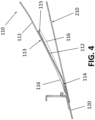
- the coupling structure extends from the edge of the dome-shaped structure at a certain angle with respect to the skin of the fuselage section, so as to approach progressively, that is, gradually at a lesser distance with respect to said skin, up to the point of contact with the foot portion to which it is connected by means of its distal portion.
- said coupling structure primarily works in tension, withstanding traction forces.
- the shearwebs of the prior art which are attached along their longitudinal length to the skin by means of a riveted joint, distribute the loads induced from the dome-shaped structure as shear stresses.
- said distance displaced is gained as additional pressurized area without enlarging the forward fuselage.
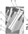
- the plate-shaped fittings (112) of the embodiment shown in Figures 3 and 4 comprise a stiffener (116). More in particular, the plate-shaped fittings (112) comprise two reinforcing walls (116) arranged on opposite surfaces of the plate-shaped fittings (112), between the edge of the dome-shaped structure (111) and the distal portion (113) of the plate-shaped fitting (112), in a plane of symmetry thereof.
Landscapes
- Engineering & Computer Science (AREA)
- Mechanical Engineering (AREA)
- Aviation & Aerospace Engineering (AREA)
- Pressure Vessels And Lids Thereof (AREA)
- Tires In General (AREA)
- Connection Of Plates (AREA)
Claims (15)
- Section de fuselage (100) pour un aéronef (200), comprenant :une cloison étanche (110) comprenant une structure en forme de dôme (111) et au moins une structure de couplage (112) s'étendant depuis le bord (113) de la structure en forme de dôme (111), etau moins une structure circonférentielle (120) agencée sur un revêtement (210) de la section de fuselage (100),dans laquelle la structure en forme de dôme (111) est fixée à la structure circonférentielle (120) par l'intermédiaire d'une partie distale (114) de la structure de couplage (112),dans laquelle ladite partie distale (114) est couplée à une partie de base (121) de la structure circonférentielle (120), la structure de couplage (112) s'étendant obliquement depuis la partie de base (121) de la structure circonférentielle (120), de manière telle que la distance entre le revêtement (210) de la section de fuselage (100) et la structure de couplage (112) augmente depuis la partie de base (121) jusqu'au bord (113) de la structure en forme de dôme (111).
- Section de fuselage (100) selon la revendication 1, dans laquelle au moins une structure de couplage (112) est une extension incorporée de la structure en forme de dôme (111).
- Section de fuselage (100) selon de quelconques des revendications précédentes, dans laquelle au moins une structure de couplage (112) est un raccord, en forme de plaque, couplé, par une partie proximale (115), au bord (113) de la structure en forme de dôme (111).
- Section de fuselage (100) selon la revendication 3, dans laquelle le raccord en forme de plaque (112) est fixé au bord (113) de la structure en forme de dôme (111) au moyen d'un joint riveté.
- Section de fuselage (100) selon de quelconques des revendications précédentes, dans laquelle la structure de couplage (112) est couplée à la structure circonférentielle (120) au moyen d'un joint riveté.
- Section de fuselage (100) selon de quelconques des revendications précédentes, dans laquelle la partie de base (121) de la structure circonférentielle (120) est en forme de plaque, et dans laquelle la partie distale (114) de la structure de couplage (112) comprend une partie sensiblement plate entrant en contact, le long de sa surface, avec une surface respective de la partie de base en forme de plaque (121).
- Section de fuselage selon de quelconques des revendications précédentes, dans laquelle la structure circonférentielle (120) est un cadre de la section de fuselage (100).
- Section de fuselage (100) selon de quelconques des revendications 1 à 6, dans laquelle la structure circonférentielle (120) est un couvre-joint configuré pour fixer ensemble le revêtement (210) de la section de fuselage (100) au revêtement d'une autre section de fuselage.
- Section de fuselage (100) selon de quelconques des revendications précédentes, dans laquelle la structure de couplage (112) comprend un raidisseur (116).
- Section de fuselage (100) selon la revendication 9, dans laquelle le raidisseur (116) est une paroi de renfort agencée depuis le bord de la structure en forme de dôme (111) jusqu'à la partie distale (113) de la structure de couplage (112).
- Section de fuselage (100) selon de quelconques des revendications 9 ou 10, dans laquelle le raidisseur (116) est agencé dans un plan de symétrie de la structure de couplage (112).
- Section de fuselage (100) selon de quelconques des revendications 10 ou 11, dans laquelle la structure de couplage (112) comprend deux parois de renfort (116) agencées sur des surfaces opposées de celle-ci, dans laquelle la hauteur d'une paroi de renfort (116), par rapport à la surface de la structure de couplage (112) à partir de laquelle elle fait saillie, diminue progressivement le long de la direction depuis le bord de la structure en forme de dôme (111) jusqu'à la partie distale (113) de la structure de couplage (112),
et dans laquelle
la hauteur de la paroi de renfort opposée (116), par rapport à la surface de la structure de couplage (112) à partir de laquelle elle fait saillie, diminue progressivement le long de la direction depuis la partie distale (113) de la structure de couplage (112) jusqu'au bord de la structure en forme de dôme (111). - Section de fuselage (100) selon de quelconques des revendications précédentes, comprenant en outre une pluralité de structures de couplage (112) s'étendant depuis le bord (113) de la structure en forme de dôme (111), dans laquelle la structure en forme de dôme (111) est fixée à la structure circonférentielle (120) par l'intermédiaire d'une partie distale (114) de chaque structure de couplage (112), dans laquelle chaque partie distale (114) est couplée à la partie de base (121) de la structure circonférentielle (120), chaque structure de couplage (120) s'étendant depuis la partie distale correspondante (114) obliquement par rapport à la partie de base (121) de la structure circonférentielle (120), de manière telle que la distance entre le revêtement (210) de la section de fuselage (100) et la structure de couplage (112) augmente depuis la partie distale (114) jusqu'au bord (113) de la structure en forme de dôme (111).
- Section de fuselage (100) selon la revendication 13, dans laquelle la pluralité de structures de couplage (112) est agencée par-dessus le bord (113) de la structure en forme de dôme (111) avec symétrie radiale.
- Aéronef (200), comprenant :une section de fuselage (100) selon de quelconques des revendications 1 à 14, etune seconde section de fuselage configurée pour être pressurisée.
Priority Applications (4)
| Application Number | Priority Date | Filing Date | Title |
|---|---|---|---|
| EP22382663.7A EP4306407B1 (fr) | 2022-07-13 | 2022-07-13 | Fixation de cloison de pressurisation |
| ES22382663T ES3032500T3 (en) | 2022-07-13 | 2022-07-13 | Pressure bulkhead attachment |
| CN202310863630.0A CN117401147A (zh) | 2022-07-13 | 2023-07-13 | 用于飞行器的机身区段和飞行器 |
| US18/351,865 US12409924B2 (en) | 2022-07-13 | 2023-07-13 | Pressure bulkhead attachment |
Applications Claiming Priority (1)
| Application Number | Priority Date | Filing Date | Title |
|---|---|---|---|
| EP22382663.7A EP4306407B1 (fr) | 2022-07-13 | 2022-07-13 | Fixation de cloison de pressurisation |
Publications (2)
| Publication Number | Publication Date |
|---|---|
| EP4306407A1 EP4306407A1 (fr) | 2024-01-17 |
| EP4306407B1 true EP4306407B1 (fr) | 2025-03-12 |
Family
ID=82608609
Family Applications (1)
| Application Number | Title | Priority Date | Filing Date |
|---|---|---|---|
| EP22382663.7A Active EP4306407B1 (fr) | 2022-07-13 | 2022-07-13 | Fixation de cloison de pressurisation |
Country Status (4)
| Country | Link |
|---|---|
| US (1) | US12409924B2 (fr) |
| EP (1) | EP4306407B1 (fr) |
| CN (1) | CN117401147A (fr) |
| ES (1) | ES3032500T3 (fr) |
Family Cites Families (12)
| Publication number | Priority date | Publication date | Assignee | Title |
|---|---|---|---|---|
| AT405813B (de) * | 1997-11-10 | 1999-11-25 | Fischer Adv Components Gmbh | Druckspant, insbesondere für flugzeuge |
| DE102007052140B4 (de) * | 2007-10-31 | 2012-10-25 | Airbus Operations Gmbh | Struktur, insbesondere Rumpfstruktur eines Luft- oder Raumfahrzeugs |
| DE102008040213B4 (de) * | 2008-07-07 | 2011-08-25 | Airbus Operations GmbH, 21129 | Verfahren zur Montage eines kalottenförmigen Druckschotts in einer Hecksektion eines Flugzeugs sowie Vorrichtung zur Durchführung des Verfahrens |
| ES2347122B1 (es) * | 2009-03-31 | 2011-08-11 | Airbus Operations, S.L. | Estructura de ensamblaje del mamparo de presion de una aeronave. |
| ES2376098B1 (es) * | 2009-07-24 | 2013-02-04 | Airbus Operations S.L. | Procedimiento de ensamblaje de secciones de fuselaje de una aeronave. |
| DE102009049007A1 (de) * | 2009-10-09 | 2011-04-21 | Airbus Operations Gmbh | Druckrumpf eines Flugzeuges mit heckseitiger Druckkalotte |
| RU2472671C1 (ru) * | 2011-09-01 | 2013-01-20 | Закрытое акционерное общество "Гражданские самолеты Сухого" | Узел стыка отсеков фюзеляжа самолета и его гермошпангоут |
| EP3064430B1 (fr) * | 2015-03-06 | 2018-11-14 | Airbus Operations GmbH | Cloison de pressurisation arrière étendue |
| ES2712855T3 (es) * | 2016-05-13 | 2019-05-16 | Airbus Operations Gmbh | Sistema de mamparo de presión |
| US10926857B2 (en) * | 2016-06-17 | 2021-02-23 | The Boeing Company | Pressurized bulkhead |
| US10926858B2 (en) * | 2017-08-07 | 2021-02-23 | The Boeing Company | Pressure bulkhead system |
| ES2909500T3 (es) * | 2019-07-30 | 2022-05-06 | Airbus Sas | Mamparo de presión |
-
2022
- 2022-07-13 EP EP22382663.7A patent/EP4306407B1/fr active Active
- 2022-07-13 ES ES22382663T patent/ES3032500T3/es active Active
-
2023
- 2023-07-13 CN CN202310863630.0A patent/CN117401147A/zh active Pending
- 2023-07-13 US US18/351,865 patent/US12409924B2/en active Active
Also Published As
| Publication number | Publication date |
|---|---|
| ES3032500T3 (en) | 2025-07-21 |
| CN117401147A (zh) | 2024-01-16 |
| US20240017813A1 (en) | 2024-01-18 |
| US12409924B2 (en) | 2025-09-09 |
| EP4306407A1 (fr) | 2024-01-17 |
Similar Documents
| Publication | Publication Date | Title |
|---|---|---|
| US8186622B2 (en) | Aircraft component | |
| EP2727821B1 (fr) | Raccord circonférentiel pour l'assemblage de coques | |
| CN102317154B (zh) | 一种复合结构桁架的方法与系统 | |
| US20120001023A1 (en) | Aircraft fuselage made out with composite material and manufacturing processes | |
| US12012198B2 (en) | Pressure bulkhead | |
| US10501163B2 (en) | Pressure bulkhead for an aircraft fuselage, and an aircraft comprising such a pressure bulkhead | |
| EP4112447A1 (fr) | Agencement structural pour un ensemble d'ailes haubanées d'un aéronef | |
| EP3257742B1 (fr) | Cloison sous pression | |
| US10364017B2 (en) | Structural component | |
| US11440634B2 (en) | Frame for fuselage shells of an aircraft and fuselage shell | |
| EP4306407B1 (fr) | Fixation de cloison de pressurisation | |
| US20030098396A1 (en) | Apparatus for load transfer between aerospace vehicle components, aerospace vehicles including same, and method of attachment of aerospace vehicle components | |
| EP3643600B1 (fr) | Ensemble de joint de cloison | |
| US20110073711A1 (en) | Joining of structural aircraft elements | |
| EP3636539A1 (fr) | Panneau pour aéronef |
Legal Events
| Date | Code | Title | Description |
|---|---|---|---|
| PUAI | Public reference made under article 153(3) epc to a published international application that has entered the european phase |
Free format text: ORIGINAL CODE: 0009012 |
|
| STAA | Information on the status of an ep patent application or granted ep patent |
Free format text: STATUS: THE APPLICATION HAS BEEN PUBLISHED |
|
| AK | Designated contracting states |
Kind code of ref document: A1 Designated state(s): AL AT BE BG CH CY CZ DE DK EE ES FI FR GB GR HR HU IE IS IT LI LT LU LV MC MK MT NL NO PL PT RO RS SE SI SK SM TR |
|
| STAA | Information on the status of an ep patent application or granted ep patent |
Free format text: STATUS: REQUEST FOR EXAMINATION WAS MADE |
|
| 17P | Request for examination filed |
Effective date: 20240530 |
|
| RBV | Designated contracting states (corrected) |
Designated state(s): AL AT BE BG CH CY CZ DE DK EE ES FI FR GB GR HR HU IE IS IT LI LT LU LV MC MK MT NL NO PL PT RO RS SE SI SK SM TR |
|
| GRAP | Despatch of communication of intention to grant a patent |
Free format text: ORIGINAL CODE: EPIDOSNIGR1 |
|
| STAA | Information on the status of an ep patent application or granted ep patent |
Free format text: STATUS: GRANT OF PATENT IS INTENDED |
|
| RIC1 | Information provided on ipc code assigned before grant |
Ipc: B64C 1/12 20060101ALN20240923BHEP Ipc: B64C 1/06 20060101ALI20240923BHEP Ipc: B64C 1/10 20060101AFI20240923BHEP |
|
| INTG | Intention to grant announced |
Effective date: 20241011 |
|
| GRAS | Grant fee paid |
Free format text: ORIGINAL CODE: EPIDOSNIGR3 |
|
| GRAA | (expected) grant |
Free format text: ORIGINAL CODE: 0009210 |
|
| STAA | Information on the status of an ep patent application or granted ep patent |
Free format text: STATUS: THE PATENT HAS BEEN GRANTED |
|
| AK | Designated contracting states |
Kind code of ref document: B1 Designated state(s): AL AT BE BG CH CY CZ DE DK EE ES FI FR GB GR HR HU IE IS IT LI LT LU LV MC MK MT NL NO PL PT RO RS SE SI SK SM TR |
|
| REG | Reference to a national code |
Ref country code: GB Ref legal event code: FG4D |
|
| REG | Reference to a national code |
Ref country code: CH Ref legal event code: EP |
|
| REG | Reference to a national code |
Ref country code: DE Ref legal event code: R096 Ref document number: 602022011693 Country of ref document: DE |
|
| REG | Reference to a national code |
Ref country code: IE Ref legal event code: FG4D |
|
| PG25 | Lapsed in a contracting state [announced via postgrant information from national office to epo] |
Ref country code: RS Free format text: LAPSE BECAUSE OF FAILURE TO SUBMIT A TRANSLATION OF THE DESCRIPTION OR TO PAY THE FEE WITHIN THE PRESCRIBED TIME-LIMIT Effective date: 20250612 |
|
| PG25 | Lapsed in a contracting state [announced via postgrant information from national office to epo] |
Ref country code: FI Free format text: LAPSE BECAUSE OF FAILURE TO SUBMIT A TRANSLATION OF THE DESCRIPTION OR TO PAY THE FEE WITHIN THE PRESCRIBED TIME-LIMIT Effective date: 20250312 |
|
| REG | Reference to a national code |
Ref country code: LT Ref legal event code: MG9D |
|
| PG25 | Lapsed in a contracting state [announced via postgrant information from national office to epo] |
Ref country code: NO Free format text: LAPSE BECAUSE OF FAILURE TO SUBMIT A TRANSLATION OF THE DESCRIPTION OR TO PAY THE FEE WITHIN THE PRESCRIBED TIME-LIMIT Effective date: 20250612 |
|
| PG25 | Lapsed in a contracting state [announced via postgrant information from national office to epo] |
Ref country code: HR Free format text: LAPSE BECAUSE OF FAILURE TO SUBMIT A TRANSLATION OF THE DESCRIPTION OR TO PAY THE FEE WITHIN THE PRESCRIBED TIME-LIMIT Effective date: 20250312 |
|
| REG | Reference to a national code |
Ref country code: NL Ref legal event code: MP Effective date: 20250312 |
|
| PG25 | Lapsed in a contracting state [announced via postgrant information from national office to epo] |
Ref country code: LV Free format text: LAPSE BECAUSE OF FAILURE TO SUBMIT A TRANSLATION OF THE DESCRIPTION OR TO PAY THE FEE WITHIN THE PRESCRIBED TIME-LIMIT Effective date: 20250312 |
|
| PG25 | Lapsed in a contracting state [announced via postgrant information from national office to epo] |
Ref country code: GR Free format text: LAPSE BECAUSE OF FAILURE TO SUBMIT A TRANSLATION OF THE DESCRIPTION OR TO PAY THE FEE WITHIN THE PRESCRIBED TIME-LIMIT Effective date: 20250613 Ref country code: BG Free format text: LAPSE BECAUSE OF FAILURE TO SUBMIT A TRANSLATION OF THE DESCRIPTION OR TO PAY THE FEE WITHIN THE PRESCRIBED TIME-LIMIT Effective date: 20250312 |
|
| REG | Reference to a national code |
Ref country code: ES Ref legal event code: FG2A Ref document number: 3032500 Country of ref document: ES Kind code of ref document: T3 Effective date: 20250721 |
|
| REG | Reference to a national code |
Ref country code: AT Ref legal event code: MK05 Ref document number: 1774838 Country of ref document: AT Kind code of ref document: T Effective date: 20250312 |
|
| PG25 | Lapsed in a contracting state [announced via postgrant information from national office to epo] |
Ref country code: NL Free format text: LAPSE BECAUSE OF FAILURE TO SUBMIT A TRANSLATION OF THE DESCRIPTION OR TO PAY THE FEE WITHIN THE PRESCRIBED TIME-LIMIT Effective date: 20250312 |
|
| PG25 | Lapsed in a contracting state [announced via postgrant information from national office to epo] |
Ref country code: SE Free format text: LAPSE BECAUSE OF FAILURE TO SUBMIT A TRANSLATION OF THE DESCRIPTION OR TO PAY THE FEE WITHIN THE PRESCRIBED TIME-LIMIT Effective date: 20250312 |
|
| PG25 | Lapsed in a contracting state [announced via postgrant information from national office to epo] |
Ref country code: SM Free format text: LAPSE BECAUSE OF FAILURE TO SUBMIT A TRANSLATION OF THE DESCRIPTION OR TO PAY THE FEE WITHIN THE PRESCRIBED TIME-LIMIT Effective date: 20250312 |
|
| PG25 | Lapsed in a contracting state [announced via postgrant information from national office to epo] |
Ref country code: PT Free format text: LAPSE BECAUSE OF FAILURE TO SUBMIT A TRANSLATION OF THE DESCRIPTION OR TO PAY THE FEE WITHIN THE PRESCRIBED TIME-LIMIT Effective date: 20250714 |
|
| PGFP | Annual fee paid to national office [announced via postgrant information from national office to epo] |
Ref country code: ES Payment date: 20250827 Year of fee payment: 4 |
|
| PGFP | Annual fee paid to national office [announced via postgrant information from national office to epo] |
Ref country code: DE Payment date: 20250722 Year of fee payment: 4 |
|
| PG25 | Lapsed in a contracting state [announced via postgrant information from national office to epo] |
Ref country code: IT Free format text: LAPSE BECAUSE OF FAILURE TO SUBMIT A TRANSLATION OF THE DESCRIPTION OR TO PAY THE FEE WITHIN THE PRESCRIBED TIME-LIMIT Effective date: 20250312 Ref country code: PL Free format text: LAPSE BECAUSE OF FAILURE TO SUBMIT A TRANSLATION OF THE DESCRIPTION OR TO PAY THE FEE WITHIN THE PRESCRIBED TIME-LIMIT Effective date: 20250312 |
|
| PG25 | Lapsed in a contracting state [announced via postgrant information from national office to epo] |
Ref country code: AT Free format text: LAPSE BECAUSE OF FAILURE TO SUBMIT A TRANSLATION OF THE DESCRIPTION OR TO PAY THE FEE WITHIN THE PRESCRIBED TIME-LIMIT Effective date: 20250312 |
|
| PGFP | Annual fee paid to national office [announced via postgrant information from national office to epo] |
Ref country code: FR Payment date: 20250725 Year of fee payment: 4 |
|
| PG25 | Lapsed in a contracting state [announced via postgrant information from national office to epo] |
Ref country code: EE Free format text: LAPSE BECAUSE OF FAILURE TO SUBMIT A TRANSLATION OF THE DESCRIPTION OR TO PAY THE FEE WITHIN THE PRESCRIBED TIME-LIMIT Effective date: 20250312 Ref country code: CZ Free format text: LAPSE BECAUSE OF FAILURE TO SUBMIT A TRANSLATION OF THE DESCRIPTION OR TO PAY THE FEE WITHIN THE PRESCRIBED TIME-LIMIT Effective date: 20250312 |
|
| PG25 | Lapsed in a contracting state [announced via postgrant information from national office to epo] |
Ref country code: RO Free format text: LAPSE BECAUSE OF FAILURE TO SUBMIT A TRANSLATION OF THE DESCRIPTION OR TO PAY THE FEE WITHIN THE PRESCRIBED TIME-LIMIT Effective date: 20250312 |
|
| PG25 | Lapsed in a contracting state [announced via postgrant information from national office to epo] |
Ref country code: SK Free format text: LAPSE BECAUSE OF FAILURE TO SUBMIT A TRANSLATION OF THE DESCRIPTION OR TO PAY THE FEE WITHIN THE PRESCRIBED TIME-LIMIT Effective date: 20250312 |
|
| PG25 | Lapsed in a contracting state [announced via postgrant information from national office to epo] |
Ref country code: IS Free format text: LAPSE BECAUSE OF FAILURE TO SUBMIT A TRANSLATION OF THE DESCRIPTION OR TO PAY THE FEE WITHIN THE PRESCRIBED TIME-LIMIT Effective date: 20250712 |
|
| REG | Reference to a national code |
Ref country code: DE Ref legal event code: R097 Ref document number: 602022011693 Country of ref document: DE |
|
| PG25 | Lapsed in a contracting state [announced via postgrant information from national office to epo] |
Ref country code: DK Free format text: LAPSE BECAUSE OF FAILURE TO SUBMIT A TRANSLATION OF THE DESCRIPTION OR TO PAY THE FEE WITHIN THE PRESCRIBED TIME-LIMIT Effective date: 20250312 |
|
| PLBE | No opposition filed within time limit |
Free format text: ORIGINAL CODE: 0009261 |
|
| STAA | Information on the status of an ep patent application or granted ep patent |
Free format text: STATUS: NO OPPOSITION FILED WITHIN TIME LIMIT |
|
| REG | Reference to a national code |
Ref country code: CH Ref legal event code: L10 Free format text: ST27 STATUS EVENT CODE: U-0-0-L10-L00 (AS PROVIDED BY THE NATIONAL OFFICE) Effective date: 20260121 |
|
| 26N | No opposition filed |
Effective date: 20251215 |
|
| REG | Reference to a national code |
Ref country code: CH Ref legal event code: H13 Free format text: ST27 STATUS EVENT CODE: U-0-0-H10-H13 (AS PROVIDED BY THE NATIONAL OFFICE) Effective date: 20260224 |
|
| PG25 | Lapsed in a contracting state [announced via postgrant information from national office to epo] |
Ref country code: LU Free format text: LAPSE BECAUSE OF NON-PAYMENT OF DUE FEES Effective date: 20250713 |
|
| REG | Reference to a national code |
Ref country code: BE Ref legal event code: MM Effective date: 20250731 |
|
| PG25 | Lapsed in a contracting state [announced via postgrant information from national office to epo] |
Ref country code: BE Free format text: LAPSE BECAUSE OF NON-PAYMENT OF DUE FEES Effective date: 20250731 |
|
| PG25 | Lapsed in a contracting state [announced via postgrant information from national office to epo] |
Ref country code: CH Free format text: LAPSE BECAUSE OF NON-PAYMENT OF DUE FEES Effective date: 20250731 |