EP4306410A1 - Fahrwerk mit einem dämpfungssystem - Google Patents
Fahrwerk mit einem dämpfungssystem Download PDFInfo
- Publication number
- EP4306410A1 EP4306410A1 EP23164249.7A EP23164249A EP4306410A1 EP 4306410 A1 EP4306410 A1 EP 4306410A1 EP 23164249 A EP23164249 A EP 23164249A EP 4306410 A1 EP4306410 A1 EP 4306410A1
- Authority
- EP
- European Patent Office
- Prior art keywords
- piston
- chamber
- gas
- wheel
- landing gear
- Prior art date
- Legal status (The legal status is an assumption and is not a legal conclusion. Google has not performed a legal analysis and makes no representation as to the accuracy of the status listed.)
- Granted
Links
Images

Classifications
-
- B—PERFORMING OPERATIONS; TRANSPORTING
- B64—AIRCRAFT; AVIATION; COSMONAUTICS
- B64C—AEROPLANES; HELICOPTERS
- B64C25/00—Alighting gear
- B64C25/32—Alighting gear characterised by elements which contact the ground or similar surface
- B64C25/58—Arrangements or adaptations of shock-absorbers or springs
- B64C25/60—Oleo legs
-
- B—PERFORMING OPERATIONS; TRANSPORTING
- B64—AIRCRAFT; AVIATION; COSMONAUTICS
- B64C—AEROPLANES; HELICOPTERS
- B64C25/00—Alighting gear
- B64C25/32—Alighting gear characterised by elements which contact the ground or similar surface
- B64C25/58—Arrangements or adaptations of shock-absorbers or springs
-
- F—MECHANICAL ENGINEERING; LIGHTING; HEATING; WEAPONS; BLASTING
- F16—ENGINEERING ELEMENTS AND UNITS; GENERAL MEASURES FOR PRODUCING AND MAINTAINING EFFECTIVE FUNCTIONING OF MACHINES OR INSTALLATIONS; THERMAL INSULATION IN GENERAL
- F16F—SPRINGS; SHOCK-ABSORBERS; MEANS FOR DAMPING VIBRATION
- F16F9/00—Springs, vibration-dampers, shock-absorbers, or similarly-constructed movement-dampers using a fluid or the equivalent as damping medium
- F16F9/02—Springs, vibration-dampers, shock-absorbers, or similarly-constructed movement-dampers using a fluid or the equivalent as damping medium using gas only or vacuum
- F16F9/0209—Telescopic
- F16F9/0218—Mono-tubular units
-
- F—MECHANICAL ENGINEERING; LIGHTING; HEATING; WEAPONS; BLASTING
- F16—ENGINEERING ELEMENTS AND UNITS; GENERAL MEASURES FOR PRODUCING AND MAINTAINING EFFECTIVE FUNCTIONING OF MACHINES OR INSTALLATIONS; THERMAL INSULATION IN GENERAL
- F16F—SPRINGS; SHOCK-ABSORBERS; MEANS FOR DAMPING VIBRATION
- F16F2230/00—Purpose; Design features
- F16F2230/42—Multiple pistons
-
- F—MECHANICAL ENGINEERING; LIGHTING; HEATING; WEAPONS; BLASTING
- F16—ENGINEERING ELEMENTS AND UNITS; GENERAL MEASURES FOR PRODUCING AND MAINTAINING EFFECTIVE FUNCTIONING OF MACHINES OR INSTALLATIONS; THERMAL INSULATION IN GENERAL
- F16F—SPRINGS; SHOCK-ABSORBERS; MEANS FOR DAMPING VIBRATION
- F16F9/00—Springs, vibration-dampers, shock-absorbers, or similarly-constructed movement-dampers using a fluid or the equivalent as damping medium
- F16F9/32—Details
- F16F9/3207—Constructional features
- F16F9/3214—Constructional features of pistons
-
- F—MECHANICAL ENGINEERING; LIGHTING; HEATING; WEAPONS; BLASTING
- F16—ENGINEERING ELEMENTS AND UNITS; GENERAL MEASURES FOR PRODUCING AND MAINTAINING EFFECTIVE FUNCTIONING OF MACHINES OR INSTALLATIONS; THERMAL INSULATION IN GENERAL
- F16F—SPRINGS; SHOCK-ABSORBERS; MEANS FOR DAMPING VIBRATION
- F16F9/00—Springs, vibration-dampers, shock-absorbers, or similarly-constructed movement-dampers using a fluid or the equivalent as damping medium
- F16F9/32—Details
- F16F9/3278—Details for lubrication
Definitions
- the present invention relates to a lander provided with a shock absorber system.
- an aircraft has landing gear.
- the landing gear is sometimes equipped with a plurality of undercarriages.
- the landing gear may include two main undercarriages and an auxiliary undercarriage, each of which may be swing or straight.
- An undercarriage of an aircraft may comprise at least one wheel and a shock absorber.
- an outrigger undercarriage may include an oscillating undercarriage leg, more simply called a “beam”.
- the landing gear leg is articulated to a supporting structure of the aircraft and carries at least one wheel. The landing gear leg can thus be retracted in flight into a landing gear box.
- a known pendulum undercarriage may include a strut which acts as a shock absorber and linear actuator. The strut is articulated to the undercarriage leg and to the supporting structure. The strut has a hydraulic retraction/deployment cylinder associated with a shock absorber.
- landing gears are of the wheel(s) type called “straight”, or even called “bell” or “semi-articulated”. These landing gears include a substantially vertical landing gear leg in the landing position, the landing gear leg having a shock absorber.
- a lander's shock absorber compresses and then relaxes.
- the shock absorber can also be compressed when the aircraft rolls on the ground.
- a landing gear shock absorber can take the form of an oleo-pneumatic shock absorber which produces stiffness by the compression of a gas and damping by the rolling of a liquid.
- the oleo-pneumatic shock absorber thus comprises at least one chamber filled with a gas as well as at least two chambers filled with a liquid and separated by a valve having at least one rolling passage placing the two chambers in communication with each other.
- Such an oleo-pneumatic shock absorber is interesting for a landing gear by making it possible to generate a particular reaction force during its compression.
- this reaction force increases rapidly at the start of compression of the shock absorber during a so-called “peak rolling” phase, mainly by the action of the liquid through the valve, when the compression speed of the shock absorber is maximum compared to the entire landing sequence.
- This force then increases more slowly as the shock absorber is compressed, during a phase during which the compression speed of the shock absorber will decrease and the reaction force results in an increasingly preponderant manner. of gas compression, up to a peak, and eventually decreases gently before growing again towards said peak.
- An oleo-pneumatic shock absorber is thus perfectly adapted to the needs of a lander by allowing a lot of energy to be absorbed quickly.
- Such an oleo-pneumatic shock absorber is dimensioned in order to absorb all the required energy, while minimizing both the peak of maximum effort and its size by adjusting the stroke of the piston.
- adjusting such an oleo-pneumatic shock absorber can be tricky.
- the oleo-pneumatic shock absorber can be defined to limit the risk of liquid leakage. Procedures can be put in place to detect such a leak before a flight.
- the behavior of the oleo-pneumatic shock absorber can vary depending on the temperature of the liquid.
- the compression of an oleo-pneumatic shock absorber can vary between two landings generating identical total energies, but in the presence of very different external temperatures.
- the temperature has an effect not only on the internal pressure of the gas, but also on the viscosity of the liquid, and therefore on the damping resulting from the rolling of the liquid.
- an aircraft is likely to operate in a wide range of temperatures. An oleo-pneumatic shock absorber is therefore sized to take this constraint into account.
- liquid rolling systems may include valves that are difficult to define due for example to manufacturing tolerances, dispersions in the stiffness of the springs possibly used, or even the expansion of materials in a wide range of temperatures. .
- a pneumatic block having two chambers comprising a compressed gas.
- a pneumatic block has two chambers filled with nitrogen in a body.
- a first chamber is delimited longitudinally by a control piston secured to a power rod emerging from the body, and by a floating piston.
- a second chamber is delimited by the floating piston and the body.
- the first bedroom and the second bedroom are configured to be compressed when the oleo-pneumatic shock absorber is compressed.
- the pressure prevailing in the second chamber is greater than the pressure prevailing in the first chamber at rest.
- the power rod sinks into the body. Initially, the pressure in the first chamber increases.
- Such an oleo-pneumatic shock absorber then comprises a pneumatic block having two chambers filled with gas which work in compression.
- Another type of damper has chambers filled with air and separated by at least one rolling passage.
- the documents CN 104632977 , KR10-1070893 , KR10-1551944 refer to air rolling systems.
- the object of the present invention is therefore to propose an alternative damping system aimed at limiting the risks linked to the use of chambers filled with liquid.
- the invention thus aims at a landing gear provided with at least one wheel cooperating with a damping device.
- the damper device comprises a first damper sub-assembly provided with a first chamber filled with a first gas, the first chamber being delimited by a first body and a first piston movable relative to the first body for confer a first variable volume to the first chamber sealed against the first gas, said damping device comprising a second damping sub-assembly provided with a second chamber filled with a second gas, the second chamber being delimited by a second body and by a second piston movable relative to the second body to give a second variable volume to the second chamber sealed against the second gas, the first chamber having a first pressure P1 which is maximum in a rest position of the lander preceding a landing, the second chamber having a second pressure P2 which is minimum in the rest position, a first pressure of the first gas in the first chamber decreasing when a second pressure of the second gas in the second chamber increases following the rest position during a landing.
- the first gas remains in the first chamber and the second gas remains in the second chamber during compression and extension of the shock absorber.
- the first pressure prevailing in the first chamber induces a first reaction force on the shock absorber, namely on the movable member among the first piston or the first body.
- the second pressure prevailing in the second chamber induces a second reaction force on the shock absorber, namely on the movable member among the second piston and/or the second body.
- the second reaction force resulting from the second pressure in the second chamber is directed in a direction in opposition to the direction of the first reaction force resulting from the first pressure in the first chamber. Furthermore, the second reaction force is always greater than the first reaction force. At rest, the first reaction effort is countered by the second reaction effort.
- the first body may comprise a first stop to limit the relative movement in a first direction of the first piston relative to the first body.
- the first stop thus prevents, by interference of shape with the first piston, the first pressure from exceeding the maximum pressure to be reached in the rest position, and ensures a stable rest position given that the action of the second chamber is preponderant relative to the action of the first chamber on the shock absorber.
- a first stop may comprise a shoulder.
- the second body may comprise a second stop to limit the relative movement in a second direction of the second piston relative to the second body.
- the second stop thus prevents, by interference of shape with the second piston, the second pressure from becoming lower than the minimum pressure to be reached in the rest position, and ensures a stable rest position taking into account that the action of the second chamber is preponderant in relation to the action of the first chamber on the shock absorber.
- a second stop may include a shoulder.
- the damping device does not have a fluid rolling system, which makes it possible to avoid the disadvantages linked to this technology.
- At least one wheel cooperating with a damping device means that the wheel(s) are mechanically connected to the damping device, and directly or indirectly to each damping sub-assembly, so that movement of the wheel(s) relative to a supporting structure of the aircraft stresses the damping device, for example from an activation threshold.
- each sub-assembly of the shock absorber device is activated to operate initially in a phase called “depression phase” by analogy with a conventional shock absorber followed by a phase called “return to normal phase” for convenience.
- the damper device innovatively comprises a first chamber and a second gas-filled chamber which operate separately, the first gas remaining in the first chamber and the second gas remaining in the second chamber in operation, one chamber expanding when the other chamber compresses.
- a movement of the wheel relative to a supporting structure of the aircraft in fact induces a relative movement of the first piston relative to the first body, and of the second piston relative to the second body.
- the first chamber and the second chamber behave differently.
- the first chamber relaxes during the “sinking phase” as the wheel and the supporting structure of the aircraft, for example, come closer together.
- the second chamber is compressed during the “sinking phase”.
- the second chamber conventionally operates in compression while the first chamber expands.
- the damping device thus makes it possible to generate when a wheel is driven towards the supporting structure a force which initially increases rapidly, then at a lower slope.
- This damping device can then operate in a manner substantially equivalent to a usual oleo-pneumatic damper.
- the damping device tends to return to its initial shape during the return to position phase. the normal.
- the damping device may include at least one braking system to optimize relaxation.
- the landing gear may also include one or more of the following characteristics, taken alone or in combination.
- said at least one wheel can be movable jointly with the first piston and the second piston or said at least one wheel can be movable jointly with the first body and the second body.
- the movement of the wheel(s) can generate either the movement of the first piston and the second piston respectively relative to the first body and the second body, or the movement of the first body and the second body respectively relative to the first piston and the second piston.
- the first gas and the second gas can be identical.
- the first gas and the second gas can be nitrogen for example.
- the first sub-assembly and the second sub-assembly can be arranged in series.
- the first subassembly and the second subassembly can form one and the same shock absorber module.
- a connecting rod may extend from the first piston to the second piston.
- the first piston and the second piston are thus integral in translation by being arranged one after the other in the direction of extension of the connecting rod.
- a control rod can be integral with the first piston, the control rod extending in the first chamber delimited by the first piston and outside the first body and second body, the control rod being mechanically connected to said at least one wheel or to a support.
- the first piston or the second body is then connected to the wheel or wheels.
- the control rod can pass through the first body to be mechanically connected to said at least one wheel, the second body being connected to said support.
- Sealing means can be arranged between the control rod and the first body, and/or between the first piston and the first body to maintain the first gas in the first chamber.
- the first body carries a joint along which the control rod slides.
- sealing means can be placed between the second piston and the second body to maintain the second gas in the second chamber.
- oil is trapped in a cavity of the first body, this oil being in contact with the control rod.
- This oil then has the sole function of ensuring lubrication and improving sealing, but does not provide a rolling function.
- control rod passes through the first body to be mechanically connected to the support, the second body being connected to said at least one wheel.
- Sealing means can be arranged between the control rod and the first body, and/or between the first piston and the first body to maintain the first gas in the first chamber.
- the first body carries a joint along which the control rod slides.
- sealing means can be placed between the second piston and the second body to maintain the second gas in the second chamber.
- oil is trapped in a cavity of the second body, this oil being in contact with the control rod.
- This oil then has the sole function of ensuring lubrication and improving sealing, but does not provide a rolling function.
- control rod can be articulated to the connecting rod, the control rod being mechanically connected to said at least one wheel.
- the control rod can be a connecting rod articulated by a ball joint to the connecting rod.
- This second alternative may have the advantage of not requiring sealing means between the control rod and the bodies.
- At least one of the bodies has a groove in which the control rod moves.
- This groove is configured to always be located outside the chamber delimited by this body, and whatever the position of the respective piston within an authorized movement range.
- the first body can be integral with the second body, or even the first body and the second body can form a single body open to the outside between the first piston and the second piston .
- the first piston can comprise a first surface in contact with the first gas, the second piston comprising a second surface in contact with the second gas, a first product of a first surface S1 of the first surface and the first maximum pressure P1 in the rest position being less than a second product of a second surface area S2 of the second surface and the second minimum pressure P2 in the rest position, i.e. P1*S1 ⁇ P2 *S2.
- the areas of these contact surfaces and the gas pressures in the chambers ensure that the first chamber will not relax in the absence of a threshold force generated during a landing. Only the depression of the wheel(s) towards the airframe of the aircraft will activate the damping device and the start of the depression phase.
- the first subassembly and the second subassembly can be arranged in parallel.
- the first subassembly and the second subassembly can form two separate shock absorber modules.
- the undercarriage can then comprise a train leg movable in rotation around a pivot axis, the train leg carrying said at least one wheel, a first mechanical connection extending from the first piston or the first body to there undercarriage leg, a second mechanical connection extending from the second piston or the second body to the undercarriage leg, the first mechanical connection and the second mechanical connection being hinged to the undercarriage leg on either side of the axle pivoting.
- the second mechanical connection can for example be articulated to the train leg between the pivot axis and an axis of rotation of said at least one wheel relative to the train leg.
- This architecture may in particular be of interest within an outrigger lander.
- this architecture can facilitate the arrangement of the damping device, in particular within an existing aircraft.
- the first piston can comprise a first surface in contact with the first gas, the second piston comprising a second surface in contact with the second gas, a first product of a first surface S1 of the first surface and the first maximum pressure P1 and a first distance D1 between the first mechanical connection and the pivot axis in the rest position being less than a second product of a second surface S2 of the second surface and the second minimum pressure P2 and a second distance D2 between the second mechanical connection and the pivot axis in the rest position, i.e. P1*S1*D1 ⁇ P2*S2*D2.
- the areas of these contact surfaces, the gas pressures in the chambers, the first distance and the second distance make it possible to guarantee that the first chamber will not relax in the absence of a threshold force generated during a landing. Only the driving of the wheel(s) towards the airframe of the aircraft will generate the activation of the damping device and the start of the depression phase.
- At least one of the first piston and second piston can comprise an annular cavity open on the first body or the second respective body, a lubricating fluid being maintained in said cavity.
- Fluid can be held in a cavity by seals.
- the first piston and/or the second piston then comprise a cavity filled with a fluid in contact against an internal face of the respective body.
- This fluid can be oil for example.
- the fluid only has the function of optimizing the friction between the piston concerned and the respective body, and does not provide any rolling type function. A small quantity of fluid can then be used.
- an aircraft can be equipped with at least one landing gear according to the invention.
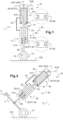
- the figures show various examples of a landing gear 10 carried by a cell 90 of an aircraft 1 according to the invention.
- the aircraft 1 can for example be an airplane, a rotorcraft or others.
- Cell 90 is represented schematically so as not to unnecessarily burden the figures for reasons of brevity.
- such a landing gear 10 is provided with at least one wheel 15 movable in rotation around an axis of rotation 16, and for example with one wheel 15 or two wheels 15.
- the wheel(s) 15 can be carried by a train leg 11 more or less complex.
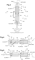
- the undercarriage leg 11 can be substantially vertical relative to the ground 100 as illustrated in the examples of figures 1 And 3 or can present another inclination as illustrated in the examples of figure 2 , 8 And 9 .
- the undercarriage leg 11 can optionally be retractable using a usual system.
- the undercarriage 10 is provided with a damping device 20 to cushion the movement of the cell 90 of the aircraft 1 towards the ground, during landing or taxiing of the aircraft on the ground 100.
- the damping device 20 can be an integral part of the train leg 11 as illustrated in the examples of figures 1 And 3 , or can cooperate with the train leg 11 according to the examples of figure 2 , 4 , 8 And 9 .
- the shock absorber device 20 comprises a first shock absorber sub-assembly 30.
- This first shock absorber sub-assembly 30 comprises a first chamber 33.
- the first chamber 33 is delimited by a first body 32 and a first piston 31 movable in a first longitudinal housing of the first body 32 to give a first variable volume to the first chamber 33.
- the first body 32 has the shape of a first tube extending from an end zone closed by a first bottom up to a first open end.
- the first chamber 33 is then delimited longitudinally along a first axis AX1 by the first bottom and the first piston 31, and radially relative to the first axis AX1 by the first tube.
- the first chamber 33 is filled in a sealed manner with a first gas 34, a first pressure P1 prevailing in the first chamber 33, and therefore a first pressure P1 of the first gas 34, varying as a function of the relative position of the first piston 31 relative to to the first body 32.
- a first surface 310 of the first piston is in contact against the first gas 34.
- the damper device 20 comprises a second damper sub-assembly 40.
- This second damper sub-assembly 40 comprises a second chamber 43.
- the second chamber 43 is delimited by a second body 42 and a second piston 41 movable in a second longitudinal housing of the second body 42 to give a second variable volume to the second chamber 43.
- the second body 42 has the shape of a second tube s extending from an end zone closed by a second bottom to a second open end.
- the second chamber 43 is then delimited longitudinally along a second axis AX2 by the second bottom and the second piston 41, and radially relative to the second axis AX2 by the second tube.
- the second chamber 43 is filled in a sealed manner with a second gas 44, a second pressure P2 prevailing in the second chamber 43, and therefore with the second gas 44, varying as a function of the position of the second piston 41 relative to the second body 42.
- a second surface 410 of the second piston is in contact against the second gas 44.
- the first gas 34 and the second gas 44 may be identical, and for example may be nitrogen.
- the first body and the second body may also include valves not shown for filling the first chamber and the second chamber, or even for taking pressure measurements as part of simple maintenance. A lack of pressure can then lead to refilling of the chambers, or even the replacement of any seals.
- At least one of the first piston 31 and second piston 41 may comprise an annular cavity 81, 83 open on the first body 32 or the second body 42 respectively.
- a lubricating fluid 82, 84 is maintained in the cavity 81, 83 between the piston 31,41 and the corresponding body 32,42, possibly using seals not shown so as not to burden the figures.
- a slice of the first piston 31 sliding along the first body 32, and in particular the first tube, can comprise a first annular cavity 81.
- a first lubricating fluid 82 oil for example, then fills the first cavity 81.
- a slice of the second piston 41 sliding along the second body 42, and in particular the second tube, may comprise a second annular cavity 83.
- the first pressure P1 in the first chamber 33 is maximum in a rest position of the undercarriage 10 preceding a landing, being equal to a pressure called "max pressure”.
- the first gas 34 exerts a force on the first surface 310 tending to move the first piston 31 to increase the first volume of the first chamber 33.
- the first pressure P1 will then be lower than the maximum pressure P1max.
- the second pressure P2 in the second chamber 43 is minimum in this rest position, being equal to a minimum pressure.
- the second pressure P2 will then be greater than the minimum pressure P2min.
- the first surface 310 of the first piston 31 can according to another aspect have a first surface S1 different from a second surface S2 of the second surface 410 of the second piston 41.
- first piston 31 as well as the second piston 41 and the wheel(s) 15 carried or the first body 32 as well as the second body 42 and the wheel(s) 15 carried are possibly movable jointly.
- a ruzement of the wheel(s) 15 and the cell 90 during a landing phase or when rolling the wheel(s) 15 on a stone or an equivalent concomitantly induces the relative movement of the first piston 31 relative to the first body 32 and the second piston 41 relative to the second body 42. Therefore, the first pressure P1 of the first gas 34 in the first chamber 33 decreases while the second pressure P2 of the second gas 44 in the second chamber 43 increases during a sinking phase, and vice versa during a return to normal phase.
- a connecting rod 50 secures the first piston 31 to the second piston 41.
- the connecting rod 50 extends from one end secured to the first piston 31 to a second end secured to the second piston 41.
- the assembly formed by the first piston 31, the connecting rod 50 and the second piston 41 can be in one piece or made up of several mechanical parts fixed to each other.
- the first axis AX1 and the second axis AX2 can be confused.
- the first axis AX1 and the second axis AX2 can form axes of symmetry respectively of the first body 32 and the second body 42.
- first longitudinal housing and the second longitudinal housing may face each other.
- the first body 32 can be made integral with the second body 42 by one or more links 55.
- At least one of the first shock absorber sub-assembly 30 and second shock absorber sub-assembly 40 can be attached to a support 5 of the cell 90.
- the first shock absorber sub-assembly 30 and the second shock absorber sub-assembly 40 are arranged in series.
- first surface area S1, the maximum pressure P1max, the second surface area S2 and the minimum pressure P2min can be defined so that a first product of the first surface area S1 and the maximum pressure P1 max is less than a second product of the second surface S2 and the minimum pressure P2min.
- a control rod 60 is integral with a reference piston 65, this reference piston 65 being the first piston 31. From then on, the control rod 60 extends into the first chamber 33 delimited by the reference piston 65 and outside the first body 32, and therefore the second body 42. The part of the control rod 60 outside the first chamber is then mechanically connected to the wheel(s) 15 of the undercarriage 10 or to a support 5 of cell 90.
- the control rod 60 then extends into the first chamber 33 and passes through a wall of the first body 31, in particular the first aforementioned bottom. Consequently, the control rod 60 is connected to the wheel(s) 15 in the usual manner, and for example to a wheel spindle according to the figure 1 or to a train leg 11 carrying a wheel spindle according to the figure 2 .
- the second body 42 is connected to a support 5, possibly via a joint in particular.
- the control rod 60 then extends into the first chamber 33 and passes through a wall of the first body 31, in particular the first aforementioned bottom. Subsequently, the control rod 60 is connected to a support 5 of the cell 90, possibly via a joint in particular.
- the second body 42 is on the contrary connected to the wheel(s) 15 in the usual manner, and for example to a wheel spindle.
- a control rod 60 is articulated to the connecting rod 50.
- the control rod 60 is then mechanically connected to the wheel(s) 15, and for example via a wheel spindle or even a train leg 11.
- the first body 32 and/or the second body 42 may comprise a groove in which the control rod 60 can in particular slide. A force exerted on the control rod 60 during movement of the wheel(s) 15 then induces a force in the connecting rod 50, and vice versa.
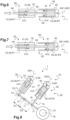
- THE figures 5 to 7 illustrate the operation of the damping device 20 of the first version.
- the damping device 20 corresponding to that of the figure 1 , but the following explanations apply to the other examples.
- the shock absorber device 20 is in a rest position just before the wheel or wheels 15 touch the ground before landing.
- the gas present in the first chamber 33 is compressed while the gas present in the second chamber 43 is expanded.
- the first piston 31 moves away according to the arrow illustrated from the first bottom, while on the contrary the second piston 41 approaches the second bottom.
- the first gas remains in the first chamber and the second gas remains in the second chamber.
- the first pressure P1 in the first chamber 33 decreases while the second pressure P2 in the second chamber 43 increases.
- the damping device 20 as a whole then generates a force which increases very quickly, the damping device absorbing a maximum of energy.
- the damping device 20 operates in a return-to-normal phase and tends to return to its initial shape.
- the damping device may include at least one braking system to optimize relaxation and avoid a rebound phenomenon.
- the undercarriage 10 comprises a train leg 11 movable in rotation around a pivot axis 12.
- This train leg 11 carries one or more wheels 15.
- the first shock absorber sub-assembly 30 and the second shock absorber sub-assembly 40 are arranged in parallel. Unlike the first version, the first shock absorber sub-assembly 30 and the second shock absorber sub-assembly 40 are separated.
- the first shock absorber sub-assembly 30 is articulated to a support 5 of the cell 90.
- the first shock absorber sub-assembly 30 is articulated by a first mechanical connection 70 to the train leg 11.
- a first distance D1 separates along the train leg 11 the pivot axis 12 and the first mechanical connection 70, and for example a first articulation 72 with a pivot or ball joint of the first mechanical connection 70 and the pivot axis 12.
- the first mechanical connection 70 extends from the first piston 31 to the train leg 11.
- This first mechanical connection 70 comprises for example a first shaft 71 secured to the first piston 31 and articulated by a first articulation 72 with a pivot or ball joint to the train leg 11, the first body 32 being able to be articulated to a support 5 of the cell 90.
- the first mechanical connection 70 comprises for example a first shaft secured to the first body 32 and articulated by a first articulation 72 with a pivot or ball joint to the train leg 11, the first piston 31 being able to be secured to a first rod articulated to a support 5 of cell 90.
- the second shock absorber sub-assembly 40 is articulated to a support 5 of the cell 90.
- the second shock absorber sub-assembly 40 is articulated by a second mechanical connection 75 to the train leg 11.
- a second distance D2 separates the long of the train leg 11 the pivot axis 12 and the second mechanical connection 75, and for example a second articulation 77 with pivot or ball joint of the second mechanical connection 75 and the pivot axis 12.
- the second mechanical connection 75 extends from the second piston 41 to the train leg 11.
- This second mechanical connection 75 comprises for example a second shaft 76 secured to the second piston 41 and articulated by a second articulation 77 with pivot or ball joint to the train leg 11, the second body 42 being able to be articulated to a support 5 of the cell 90.
- the second mechanical connection 75 comprises for example a second shaft secured to the second body 42 and articulated by a second pivot or ball joint 77 to the train leg 11, the second piston 41 being able to be secured to a second rod articulated to a support 5 of cell 90.
- first surface area S1, the maximum pressure P1max, the second surface area S2 and the minimum pressure P2min as well as the first distance D1 and the second distance D2 can be defined so that a first product of the first surface area S1 and the maximum pressure P1 max and the first distance D1 is less than a second product of the second surface area S2 and the minimum pressure P2min and the second distance D2.
- first mechanical connection 70 and the second mechanical connection 75 are articulated to the train leg 11 on either side of the pivot axis 12.
- the second mechanical connection 75 is articulated to the undercarriage leg 11 between the pivot axis 12 and the axis of rotation 16 of the wheel(s) 15 relative to the undercarriage leg 11 according to the alternative to “fixed body and movable piston” illustrated.
- the opposite is possible, for example for the alternative to “moving body and fixed piston”.
- a landing gear 10 operates in a manner substantially equivalent to a landing gear having an oleo-pneumatic shock absorber.
- FIG. 10 includes a diagram 95 showing on the abscissa the movement of a wheel and on the ordinate the reaction force generated by a damping device.
- the first curve C1 presents the evolution of the reaction force caused by an oleo-pneumatic shock absorber.
- the reaction force caused by a conventional oleopneumatic shock absorber corresponds substantially to the sum of the reaction force caused by the pneumatic part of the oleopneumatic shock absorber and illustrated by the curve C3 and the reaction force caused by the rolling of a liquid from the oleo-pneumatic shock absorber and illustrated by the curve C4.
- the second curve C2 presents the evolution of the reaction force caused by a shock absorber device 20 of the type of the invention.
- the reaction force caused by the oleo-pneumatic shock absorber of the invention corresponds substantially to the sum of the force reaction caused by the expansion of the first chamber of the oleo-pneumatic shock absorber and illustrated by the curve C5 and the reaction force caused by the compression of the second chamber and illustrated by the curve C6.
- first curve C1 and the second curve C2 grow rapidly in a similar manner.
- first curve C1 and the second curve C2 evolve differently but are substantially equivalent.
- first piston 31 and/or the second piston 41 of the figures 8 And 9 may include a cavity 81, 83 housing a lubricating fluid 82, 84 like the example of the figure 1 .
- first piston 31 and/or the second piston 41 of the figures 1 to 7 may be devoid of it.
Landscapes
- Engineering & Computer Science (AREA)
- Mechanical Engineering (AREA)
- General Engineering & Computer Science (AREA)
- Aviation & Aerospace Engineering (AREA)
- Fluid-Damping Devices (AREA)
Applications Claiming Priority (1)
| Application Number | Priority Date | Filing Date | Title |
|---|---|---|---|
| FR2207121A FR3137893B1 (fr) | 2022-07-12 | 2022-07-12 | Atterrisseur muni d’un système amortisseur |
Publications (2)
| Publication Number | Publication Date |
|---|---|
| EP4306410A1 true EP4306410A1 (de) | 2024-01-17 |
| EP4306410B1 EP4306410B1 (de) | 2025-01-15 |
Family
ID=83438346
Family Applications (1)
| Application Number | Title | Priority Date | Filing Date |
|---|---|---|---|
| EP23164249.7A Active EP4306410B1 (de) | 2022-07-12 | 2023-03-27 | Fahrwerk mit einem dämpfungssystem |
Country Status (3)
| Country | Link |
|---|---|
| EP (1) | EP4306410B1 (de) |
| CA (1) | CA3194127C (de) |
| FR (1) | FR3137893B1 (de) |
Citations (8)
| Publication number | Priority date | Publication date | Assignee | Title |
|---|---|---|---|---|
| US1904372A (en) | 1931-04-03 | 1933-04-18 | Peter W Kane | Pneumatic shock absorber |
| US2139192A (en) | 1935-01-28 | 1938-12-06 | Krekel Paul | Aircraft undercarriage |
| KR101070893B1 (ko) | 2004-06-16 | 2011-10-06 | 삼성테크윈 주식회사 | 에어 포일 베어링, 에어 포일 베어링의 충격 감쇠 시스템및 에어 포일 베어링의 충격 감쇠 방법 |
| CN203979249U (zh) | 2014-07-01 | 2014-12-03 | 浙江欣康科技有限公司 | 双活塞气弹簧结构 |
| CN104632977A (zh) | 2015-01-30 | 2015-05-20 | 常州市达文电动车辆配件厂 | 一种气压阻尼机构及应用该机构的气压阻尼减震器 |
| KR101551944B1 (ko) | 2010-04-09 | 2015-09-09 | 현대자동차주식회사 | 솔레노이드 밸브를 이용한 에어 댐핑 마운트 |
| US20190061867A1 (en) | 2017-08-28 | 2019-02-28 | Trvstper, Inc. | Inline Shock Absorber with Gas Spring for a Cycle Wheel Suspension Assembly |
| CN212360608U (zh) | 2020-05-20 | 2021-01-15 | 无锡骏逸通用设备有限公司 | 一种带有双向缓冲功能的双管串联结构的气弹簧 |
-
2022
- 2022-07-12 FR FR2207121A patent/FR3137893B1/fr active Active
-
2023
- 2023-03-24 CA CA3194127A patent/CA3194127C/fr active Active
- 2023-03-27 EP EP23164249.7A patent/EP4306410B1/de active Active
Patent Citations (8)
| Publication number | Priority date | Publication date | Assignee | Title |
|---|---|---|---|---|
| US1904372A (en) | 1931-04-03 | 1933-04-18 | Peter W Kane | Pneumatic shock absorber |
| US2139192A (en) | 1935-01-28 | 1938-12-06 | Krekel Paul | Aircraft undercarriage |
| KR101070893B1 (ko) | 2004-06-16 | 2011-10-06 | 삼성테크윈 주식회사 | 에어 포일 베어링, 에어 포일 베어링의 충격 감쇠 시스템및 에어 포일 베어링의 충격 감쇠 방법 |
| KR101551944B1 (ko) | 2010-04-09 | 2015-09-09 | 현대자동차주식회사 | 솔레노이드 밸브를 이용한 에어 댐핑 마운트 |
| CN203979249U (zh) | 2014-07-01 | 2014-12-03 | 浙江欣康科技有限公司 | 双活塞气弹簧结构 |
| CN104632977A (zh) | 2015-01-30 | 2015-05-20 | 常州市达文电动车辆配件厂 | 一种气压阻尼机构及应用该机构的气压阻尼减震器 |
| US20190061867A1 (en) | 2017-08-28 | 2019-02-28 | Trvstper, Inc. | Inline Shock Absorber with Gas Spring for a Cycle Wheel Suspension Assembly |
| CN212360608U (zh) | 2020-05-20 | 2021-01-15 | 无锡骏逸通用设备有限公司 | 一种带有双向缓冲功能的双管串联结构的气弹簧 |
Also Published As
| Publication number | Publication date |
|---|---|
| EP4306410B1 (de) | 2025-01-15 |
| FR3137893B1 (fr) | 2024-10-25 |
| CA3194127C (fr) | 2025-12-23 |
| CA3194127A1 (fr) | 2024-01-12 |
| FR3137893A1 (fr) | 2024-01-19 |
Similar Documents
| Publication | Publication Date | Title |
|---|---|---|
| CA1177500A (fr) | Amortisseur-verin | |
| EP2048408B1 (de) | Stoßdämpfer eines Fahrzeugs | |
| EP0246949B1 (de) | Flugzeugfahrwerk mit einem Schwenkbalken und geringerem Raumbedarf | |
| EP0072323B1 (de) | Mit einer Energieaufnahmevorrichtung durch plastische Verformung und/oder Kraftbegrenzung ausgerüstete Elemente, und Flugzeugfahrgestelle mit derartigen Elementen | |
| EP2048078B1 (de) | Einfahrzylinder und mit einem solchen Einfahrzylinder ausgestattetes Fahrwerk eines Drehflügelflugzeugs | |
| EP0275735A1 (de) | Landungsbein mit Dämpferheber und Flugzeugfahrgestelle, ausgerüstet mit einem derartigen Landungsbein | |
| EP0014660B1 (de) | Dämpfer und Dämpfer-Kraftzylinder, insbesondere für Fahrgestelle von Flugzeugen | |
| FR2686857A1 (fr) | Amortisseur de jambe de train d'atterrissage d'aeronef. | |
| FR2461852A1 (fr) | Perfectionnements aux amortisseurs et amortisseurs-verins notamment pour trains d'atterrissage d'aerodyne | |
| EP1493661B1 (de) | Einziehfahrwerk mit unabhängigen Fahrwerksbeinen und vertikaler Bewegung | |
| FR2689088A1 (fr) | Amortisseur-vérin destiné à l'équipement d'atterrisseurs d'aérodynes, notamment d'hélicoptères. | |
| EP4306410B1 (de) | Fahrwerk mit einem dämpfungssystem | |
| EP1581424A1 (de) | Fahrwerk-federbeindämpfer und diesen enthaltendes fahrwerk mit unabhängigen federbeinen | |
| EP2614269A1 (de) | Praktisch ölfreie stossdämpfer mit hoher dissipativer kapazität | |
| EP2481946A1 (de) | Verbesserte Zugdämpfungsvorrichtung | |
| EP3997356B1 (de) | Hydraulischer endanschlag für einen dämpfer | |
| FR2530763A1 (fr) | Amortisseur retractable | |
| EP1332963B1 (de) | Fahrwerkstossdämpfer und Fahrwerk mit unabhängigen Fahrgestellstreben mit solchem Stossdämpfer | |
| FR2472699A1 (fr) | Perfectionnements aux amortisseurs-verins | |
| FR2777058A1 (fr) | Dispositif de suspension et d'amortissement a deux combines suspension-amortisseur | |
| EP3546789A1 (de) | Hydroelastischer stossdämpfer, und luftfahrzeug | |
| FR3122714A1 (fr) | Systeme de butee hydraulique comprenant une bague comportant des moyens d’obstacle a l’ecoulement dans une chambre de compensation | |
| FR2988453A1 (fr) | Amortisseur hydraulique comprenant une chambre de compensation et une butee deportee | |
| BE417022A (de) | ||
| BE433160A (de) |
Legal Events
| Date | Code | Title | Description |
|---|---|---|---|
| PUAI | Public reference made under article 153(3) epc to a published international application that has entered the european phase |
Free format text: ORIGINAL CODE: 0009012 |
|
| STAA | Information on the status of an ep patent application or granted ep patent |
Free format text: STATUS: THE APPLICATION HAS BEEN PUBLISHED |
|
| AK | Designated contracting states |
Kind code of ref document: A1 Designated state(s): AL AT BE BG CH CY CZ DE DK EE ES FI FR GB GR HR HU IE IS IT LI LT LU LV MC ME MK MT NL NO PL PT RO RS SE SI SK SM TR |
|
| STAA | Information on the status of an ep patent application or granted ep patent |
Free format text: STATUS: REQUEST FOR EXAMINATION WAS MADE |
|
| 17P | Request for examination filed |
Effective date: 20240119 |
|
| P01 | Opt-out of the competence of the unified patent court (upc) registered |
Effective date: 20240119 |
|
| RBV | Designated contracting states (corrected) |
Designated state(s): AL AT BE BG CH CY CZ DE DK EE ES FI FR GB GR HR HU IE IS IT LI LT LU LV MC ME MK MT NL NO PL PT RO RS SE SI SK SM TR |
|
| GRAP | Despatch of communication of intention to grant a patent |
Free format text: ORIGINAL CODE: EPIDOSNIGR1 |
|
| STAA | Information on the status of an ep patent application or granted ep patent |
Free format text: STATUS: GRANT OF PATENT IS INTENDED |
|
| RIC1 | Information provided on ipc code assigned before grant |
Ipc: F16F 9/32 20060101ALI20240916BHEP Ipc: B64C 25/60 20060101ALI20240916BHEP Ipc: B60G 15/08 20060101ALI20240916BHEP Ipc: F16F 9/02 20060101ALI20240916BHEP Ipc: B64C 25/58 20060101AFI20240916BHEP |
|
| INTG | Intention to grant announced |
Effective date: 20241002 |
|
| GRAS | Grant fee paid |
Free format text: ORIGINAL CODE: EPIDOSNIGR3 |
|
| GRAA | (expected) grant |
Free format text: ORIGINAL CODE: 0009210 |
|
| STAA | Information on the status of an ep patent application or granted ep patent |
Free format text: STATUS: THE PATENT HAS BEEN GRANTED |
|
| AK | Designated contracting states |
Kind code of ref document: B1 Designated state(s): AL AT BE BG CH CY CZ DE DK EE ES FI FR GB GR HR HU IE IS IT LI LT LU LV MC ME MK MT NL NO PL PT RO RS SE SI SK SM TR |
|
| REG | Reference to a national code |
Ref country code: CH Ref legal event code: EP Ref country code: GB Ref legal event code: FG4D Free format text: NOT ENGLISH |
|
| REG | Reference to a national code |
Ref country code: DE Ref legal event code: R096 Ref document number: 602023001636 Country of ref document: DE |
|
| REG | Reference to a national code |
Ref country code: IE Ref legal event code: FG4D Free format text: LANGUAGE OF EP DOCUMENT: FRENCH |
|
| PGFP | Annual fee paid to national office [announced via postgrant information from national office to epo] |
Ref country code: AT Payment date: 20250417 Year of fee payment: 3 |
|
| REG | Reference to a national code |
Ref country code: NL Ref legal event code: MP Effective date: 20250115 |
|
| PG25 | Lapsed in a contracting state [announced via postgrant information from national office to epo] |
Ref country code: NL Free format text: LAPSE BECAUSE OF FAILURE TO SUBMIT A TRANSLATION OF THE DESCRIPTION OR TO PAY THE FEE WITHIN THE PRESCRIBED TIME-LIMIT Effective date: 20250115 |
|
| PG25 | Lapsed in a contracting state [announced via postgrant information from national office to epo] |
Ref country code: RS Free format text: LAPSE BECAUSE OF FAILURE TO SUBMIT A TRANSLATION OF THE DESCRIPTION OR TO PAY THE FEE WITHIN THE PRESCRIBED TIME-LIMIT Effective date: 20250415 |
|
| PG25 | Lapsed in a contracting state [announced via postgrant information from national office to epo] |
Ref country code: FI Free format text: LAPSE BECAUSE OF FAILURE TO SUBMIT A TRANSLATION OF THE DESCRIPTION OR TO PAY THE FEE WITHIN THE PRESCRIBED TIME-LIMIT Effective date: 20250115 |
|
| PG25 | Lapsed in a contracting state [announced via postgrant information from national office to epo] |
Ref country code: PL Free format text: LAPSE BECAUSE OF FAILURE TO SUBMIT A TRANSLATION OF THE DESCRIPTION OR TO PAY THE FEE WITHIN THE PRESCRIBED TIME-LIMIT Effective date: 20250115 |
|
| PG25 | Lapsed in a contracting state [announced via postgrant information from national office to epo] |
Ref country code: ES Free format text: LAPSE BECAUSE OF FAILURE TO SUBMIT A TRANSLATION OF THE DESCRIPTION OR TO PAY THE FEE WITHIN THE PRESCRIBED TIME-LIMIT Effective date: 20250115 |
|
| REG | Reference to a national code |
Ref country code: LT Ref legal event code: MG9D |
|
| PG25 | Lapsed in a contracting state [announced via postgrant information from national office to epo] |
Ref country code: IS Free format text: LAPSE BECAUSE OF FAILURE TO SUBMIT A TRANSLATION OF THE DESCRIPTION OR TO PAY THE FEE WITHIN THE PRESCRIBED TIME-LIMIT Effective date: 20250515 Ref country code: NO Free format text: LAPSE BECAUSE OF FAILURE TO SUBMIT A TRANSLATION OF THE DESCRIPTION OR TO PAY THE FEE WITHIN THE PRESCRIBED TIME-LIMIT Effective date: 20250415 |
|
| PGFP | Annual fee paid to national office [announced via postgrant information from national office to epo] |
Ref country code: IT Payment date: 20250331 Year of fee payment: 3 |
|
| REG | Reference to a national code |
Ref country code: AT Ref legal event code: MK05 Ref document number: 1759714 Country of ref document: AT Kind code of ref document: T Effective date: 20250115 |
|
| PG25 | Lapsed in a contracting state [announced via postgrant information from national office to epo] |
Ref country code: HR Free format text: LAPSE BECAUSE OF FAILURE TO SUBMIT A TRANSLATION OF THE DESCRIPTION OR TO PAY THE FEE WITHIN THE PRESCRIBED TIME-LIMIT Effective date: 20250115 |
|
| PG25 | Lapsed in a contracting state [announced via postgrant information from national office to epo] |
Ref country code: LV Free format text: LAPSE BECAUSE OF FAILURE TO SUBMIT A TRANSLATION OF THE DESCRIPTION OR TO PAY THE FEE WITHIN THE PRESCRIBED TIME-LIMIT Effective date: 20250115 Ref country code: PT Free format text: LAPSE BECAUSE OF FAILURE TO SUBMIT A TRANSLATION OF THE DESCRIPTION OR TO PAY THE FEE WITHIN THE PRESCRIBED TIME-LIMIT Effective date: 20250515 |
|
| PG25 | Lapsed in a contracting state [announced via postgrant information from national office to epo] |
Ref country code: GR Free format text: LAPSE BECAUSE OF FAILURE TO SUBMIT A TRANSLATION OF THE DESCRIPTION OR TO PAY THE FEE WITHIN THE PRESCRIBED TIME-LIMIT Effective date: 20250416 Ref country code: BG Free format text: LAPSE BECAUSE OF FAILURE TO SUBMIT A TRANSLATION OF THE DESCRIPTION OR TO PAY THE FEE WITHIN THE PRESCRIBED TIME-LIMIT Effective date: 20250115 |
|
| PG25 | Lapsed in a contracting state [announced via postgrant information from national office to epo] |
Ref country code: AT Free format text: LAPSE BECAUSE OF FAILURE TO SUBMIT A TRANSLATION OF THE DESCRIPTION OR TO PAY THE FEE WITHIN THE PRESCRIBED TIME-LIMIT Effective date: 20250115 |
|
| PG25 | Lapsed in a contracting state [announced via postgrant information from national office to epo] |
Ref country code: SE Free format text: LAPSE BECAUSE OF FAILURE TO SUBMIT A TRANSLATION OF THE DESCRIPTION OR TO PAY THE FEE WITHIN THE PRESCRIBED TIME-LIMIT Effective date: 20250115 |
|
| PG25 | Lapsed in a contracting state [announced via postgrant information from national office to epo] |
Ref country code: SM Free format text: LAPSE BECAUSE OF FAILURE TO SUBMIT A TRANSLATION OF THE DESCRIPTION OR TO PAY THE FEE WITHIN THE PRESCRIBED TIME-LIMIT Effective date: 20250115 |
|
| PG25 | Lapsed in a contracting state [announced via postgrant information from national office to epo] |
Ref country code: DK Free format text: LAPSE BECAUSE OF FAILURE TO SUBMIT A TRANSLATION OF THE DESCRIPTION OR TO PAY THE FEE WITHIN THE PRESCRIBED TIME-LIMIT Effective date: 20250115 |
|
| PG25 | Lapsed in a contracting state [announced via postgrant information from national office to epo] |
Ref country code: MC Free format text: LAPSE BECAUSE OF FAILURE TO SUBMIT A TRANSLATION OF THE DESCRIPTION OR TO PAY THE FEE WITHIN THE PRESCRIBED TIME-LIMIT Effective date: 20250115 |
|
| REG | Reference to a national code |
Ref country code: DE Ref legal event code: R097 Ref document number: 602023001636 Country of ref document: DE |
|
| PG25 | Lapsed in a contracting state [announced via postgrant information from national office to epo] |
Ref country code: EE Free format text: LAPSE BECAUSE OF FAILURE TO SUBMIT A TRANSLATION OF THE DESCRIPTION OR TO PAY THE FEE WITHIN THE PRESCRIBED TIME-LIMIT Effective date: 20250115 Ref country code: CZ Free format text: LAPSE BECAUSE OF FAILURE TO SUBMIT A TRANSLATION OF THE DESCRIPTION OR TO PAY THE FEE WITHIN THE PRESCRIBED TIME-LIMIT Effective date: 20250115 |
|
| PG25 | Lapsed in a contracting state [announced via postgrant information from national office to epo] |
Ref country code: RO Free format text: LAPSE BECAUSE OF FAILURE TO SUBMIT A TRANSLATION OF THE DESCRIPTION OR TO PAY THE FEE WITHIN THE PRESCRIBED TIME-LIMIT Effective date: 20250115 |
|
| PG25 | Lapsed in a contracting state [announced via postgrant information from national office to epo] |
Ref country code: SK Free format text: LAPSE BECAUSE OF FAILURE TO SUBMIT A TRANSLATION OF THE DESCRIPTION OR TO PAY THE FEE WITHIN THE PRESCRIBED TIME-LIMIT Effective date: 20250115 |
|
| PG25 | Lapsed in a contracting state [announced via postgrant information from national office to epo] |
Ref country code: LU Free format text: LAPSE BECAUSE OF NON-PAYMENT OF DUE FEES Effective date: 20250327 |
|
| PLBE | No opposition filed within time limit |
Free format text: ORIGINAL CODE: 0009261 |
|
| STAA | Information on the status of an ep patent application or granted ep patent |
Free format text: STATUS: NO OPPOSITION FILED WITHIN TIME LIMIT |
|
| REG | Reference to a national code |
Ref country code: BE Ref legal event code: MM Effective date: 20250331 |
|
| 26N | No opposition filed |
Effective date: 20251016 |
|
| PG25 | Lapsed in a contracting state [announced via postgrant information from national office to epo] |
Ref country code: BE Free format text: LAPSE BECAUSE OF NON-PAYMENT OF DUE FEES Effective date: 20250331 |
|
| PG25 | Lapsed in a contracting state [announced via postgrant information from national office to epo] |
Ref country code: IE Free format text: LAPSE BECAUSE OF NON-PAYMENT OF DUE FEES Effective date: 20250327 |
|
| PGFP | Annual fee paid to national office [announced via postgrant information from national office to epo] |
Ref country code: DE Payment date: 20260319 Year of fee payment: 4 |
|
| PGFP | Annual fee paid to national office [announced via postgrant information from national office to epo] |
Ref country code: FR Payment date: 20260323 Year of fee payment: 4 |