EP4306797B1 - Windenergieanlagen-rotorblatt und windenergieanlage - Google Patents
Windenergieanlagen-rotorblatt und windenergieanlage Download PDFInfo
- Publication number
- EP4306797B1 EP4306797B1 EP22184291.7A EP22184291A EP4306797B1 EP 4306797 B1 EP4306797 B1 EP 4306797B1 EP 22184291 A EP22184291 A EP 22184291A EP 4306797 B1 EP4306797 B1 EP 4306797B1
- Authority
- EP
- European Patent Office
- Prior art keywords
- rotor blade
- control element
- wind turbine
- air control
- passively
- Prior art date
- Legal status (The legal status is an assumption and is not a legal conclusion. Google has not performed a legal analysis and makes no representation as to the accuracy of the status listed.)
- Active
Links
Images


Classifications
-
- F—MECHANICAL ENGINEERING; LIGHTING; HEATING; WEAPONS; BLASTING
- F03—MACHINES OR ENGINES FOR LIQUIDS; WIND, SPRING, OR WEIGHT MOTORS; PRODUCING MECHANICAL POWER OR A REACTIVE PROPULSIVE THRUST, NOT OTHERWISE PROVIDED FOR
- F03D—WIND MOTORS
- F03D80/00—Details, components or accessories not provided for in groups F03D1/00 - F03D17/00
- F03D80/40—Ice detection; De-icing means
- F03D80/402—De-icing by convective heating
-
- F—MECHANICAL ENGINEERING; LIGHTING; HEATING; WEAPONS; BLASTING
- F03—MACHINES OR ENGINES FOR LIQUIDS; WIND, SPRING, OR WEIGHT MOTORS; PRODUCING MECHANICAL POWER OR A REACTIVE PROPULSIVE THRUST, NOT OTHERWISE PROVIDED FOR
- F03D—WIND MOTORS
- F03D80/00—Details, components or accessories not provided for in groups F03D1/00 - F03D17/00
- F03D80/40—Ice detection; De-icing means
-
- F—MECHANICAL ENGINEERING; LIGHTING; HEATING; WEAPONS; BLASTING
- F03—MACHINES OR ENGINES FOR LIQUIDS; WIND, SPRING, OR WEIGHT MOTORS; PRODUCING MECHANICAL POWER OR A REACTIVE PROPULSIVE THRUST, NOT OTHERWISE PROVIDED FOR
- F03D—WIND MOTORS
- F03D1/00—Wind motors with rotation axis substantially parallel to the air flow entering the rotor
- F03D1/06—Rotors
- F03D1/065—Rotors characterised by their construction elements
- F03D1/0675—Rotors characterised by their construction elements of the blades
-
- F—MECHANICAL ENGINEERING; LIGHTING; HEATING; WEAPONS; BLASTING
- F03—MACHINES OR ENGINES FOR LIQUIDS; WIND, SPRING, OR WEIGHT MOTORS; PRODUCING MECHANICAL POWER OR A REACTIVE PROPULSIVE THRUST, NOT OTHERWISE PROVIDED FOR
- F03G—SPRING, WEIGHT, INERTIA OR LIKE MOTORS; MECHANICAL-POWER PRODUCING DEVICES OR MECHANISMS, NOT OTHERWISE PROVIDED FOR OR USING ENERGY SOURCES NOT OTHERWISE PROVIDED FOR
- F03G7/00—Mechanical-power-producing mechanisms, not otherwise provided for or using energy sources not otherwise provided for
- F03G7/06—Mechanical-power-producing mechanisms, not otherwise provided for or using energy sources not otherwise provided for using expansion or contraction of bodies due to heating, cooling, moistening, drying or the like
- F03G7/064—Mechanical-power-producing mechanisms, not otherwise provided for or using energy sources not otherwise provided for using expansion or contraction of bodies due to heating, cooling, moistening, drying or the like characterised by its use
-
- Y—GENERAL TAGGING OF NEW TECHNOLOGICAL DEVELOPMENTS; GENERAL TAGGING OF CROSS-SECTIONAL TECHNOLOGIES SPANNING OVER SEVERAL SECTIONS OF THE IPC; TECHNICAL SUBJECTS COVERED BY FORMER USPC CROSS-REFERENCE ART COLLECTIONS [XRACs] AND DIGESTS
- Y02—TECHNOLOGIES OR APPLICATIONS FOR MITIGATION OR ADAPTATION AGAINST CLIMATE CHANGE
- Y02E—REDUCTION OF GREENHOUSE GAS [GHG] EMISSIONS, RELATED TO ENERGY GENERATION, TRANSMISSION OR DISTRIBUTION
- Y02E10/00—Energy generation through renewable energy sources
- Y02E10/70—Wind energy
- Y02E10/72—Wind turbines with rotation axis in wind direction
Definitions
- the present invention relates to a wind turbine rotor blade and a wind turbine.
- rotor blade heating can be used. This can be done either by installing a heater on the outside of the rotor blade or by providing heated air inside the rotor blade. This can be achieved, for example, by using a heating coil that generates warm air, which is then blown into the interior of the rotor blade.
- WO 2017/021350 A1 shows a wind turbine rotor blade with a rotor blade root region and a rotor blade tip region, as well as a rotor blade heater. Furthermore, at least one web is provided along a longitudinal axis of the rotor blade. A deflection unit in the form of a web droplet can be provided on the web to reduce air turbulence during deflection.
- WO 2018/211055 shows a wind turbine rotor blade with a rotor blade heater.
- the rotor blade has a web and a deflection unit in the area of the rotor blade tip for deflecting heated air.
- EP 3 048 296 A1 shows a rotor blade of a wind turbine with a rotor blade heater.
- EP 3 048 297 A1 shows a rotor blade of a wind turbine with a rotor blade heater.
- the passively controllable air control element has a temperature-dependent section that changes its shape depending on the temperature.
- the air control element thus reacts automatically to a change in temperature, which leads to a change in the air flow.
- the temperature-dependent change in shape can be used to influence the air flow to increase efficiency.
- at least one web is provided between the pressure side and the suction side along the longitudinal direction of the rotor blade.
- the air heated by the rotor blade heater can be blown along the web towards the rotor blade tip, where it is deflected so that the heated air can flow back on the other side of the web from the rotor blade tip area to the rotor blade root area.
- At least one passively controllable air control element can be provided along a web to influence the air flow.
- the passively controllable air control element has no active control elements, only passive controllable elements. There is therefore no active intervention in the air control elements.
- the passively controllable air control element allows for temperature-dependent passive control. To this end, the air control element allows for at least partial temperature-dependent deformation.
- the passively controllable air control element can comprise a bimaterial section with a first and a second material section.
- the material of the first material section has a different thermal expansion coefficient than the material of the second material section.
- a temperature change can cause the first and second material sections to expand differently, thus resulting in deformation of the bimaterial section.
- the bimaterial section is provided as a bimetallic section with a first and second metal section with different thermal expansion coefficients.
- the first and second metal sections which are coupled to each other, expand differently, resulting in a bending of the bimetallic section toward the metal section with the lower expansion coefficient. This change in shape influences the airflow of the heated air inside the rotor blade.
- the passively controllable air control element can be configured as a passively controlled static mixer.
- the mixer has a bimaterial section with a first and second material, which are coupled to one another and have different thermal expansion coefficients.
- an air guide element is coupled to the bimaterial section.
- the deformation of the bimaterial section leads to a change in the angle of the air guide element.
- an air flow in the air guide of the rotor blade heater within the rotor blade can be changed, for example, by the passively controlled static mixer.
- the bimaterial section deforms according to the temperature, and thus the position of the air guide unit changes, which in turn leads to a change in the air flow in the air flow.
- the passively controlled air control element can be configured as a passively controlled vortex generator.
- the vortex generator can have a bimaterial section comprising a first and second material with different thermal expansion coefficients. Heating or cooling the bimaterial section results in a deformation of the bimaterial section. This causes a change in the shape of the vortex generator, which changes the air flow in the air duct of the rotor blade heater within the rotor blade. Thus, a passively controlled change in the air flow within the air duct of the rotor blade can be achieved.
- the passively controllable air control element may comprise an element that exhibits a temperature-dependent change in length.
- This element may be provided with a baffle be coupled so that, for example, the angle of the baffle changes depending on the temperature. This can result in the air flow within the air duct being deflected by the baffle, which can cause turbulence in the different temperature layers. For example, the angle of the baffle can be increased as the temperature increases.
- the passively controllable air flow elements can also be retrofitted to existing rotor blades.
- the passively controlled air control elements are optionally used to locally improve the rotor blade heating by locally influencing the air flow of the rotor blade heating.
- the passively controllable air control element has at least a first and a second operating position, wherein the air control element is active in the first operating position and inactive in the second operating position.
- the air control element can be inactive in the first operating position and active in the second operating position.
- the transition from the first to the second operating position or from the second to the first operating position occurs as a function of the temperature.
- a transition between the first and second operating positions occurs due to a non-linear linear expansion of a bimaterial element which has a first and second material section with different thermal expansion coefficients.
- the passively controlled air control elements can be active in the initial position (vortex generators VG, static mixer, flap (open)) and inactive in the final position (vortex generator VG inactive, static mixer inactive, flap (closed)), or vice versa. This can be achieved through targeted positioning or preloading by the bimaterial element.
- the passively controllable air control element can be arranged on an inner wall of the rotor blade or on a web within the rotor blade.
- the passively controllable air control element can also be attached to other components inside the rotor blade.
- one end of the passive air control element can be attached to the web or the inner wall, so that the other end protrudes into the interior volume of the rotor blade and deforms depending on the temperature.
- the passively controllable air control element with the temperature-dependent deformation can be designed as a vortex generator, static mixer and/or deflection vane.
- a passively controllable air control element can be provided that only intervenes in the air flow when needed. This is advantageous because the passively controllable air control elements only intervene in the air flow when actually needed. This can prevent, for example, a permanent pressure loss due to the passively controllable air control elements interfering with the air flow of the rotor blade heater.
- the passively controllable air control elements placed along the rotor blade allow for localized control of the rotor blade heating airflow.
- specific sections of the rotor blade can be heated more effectively thanks to the passively controllable air flow elements, preventing or reducing ice buildup.
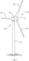
- Fig. 1 shows a schematic representation of a wind turbine according to the invention.
- the wind turbine 100 has a tower 102 and a nacelle 104 on the tower 102.
- An aerodynamic rotor 106 with three rotor blades 200 and a spinner 110 is provided on the nacelle 104.
- the aerodynamic rotor 106 is set in rotation by the wind and thus also rotates a rotor or rotor of a generator, which is directly or indirectly coupled to the aerodynamic rotor 106.
- the electrical generator is arranged in the nacelle and generates electrical energy.
- the pitch angles of the rotor blades 200 can be changed by pitch motors at the rotor blade roots 210 of the respective rotor blades 200.
- Fig. 2 shows a schematic section of the rotor blade of the wind turbine from Fig. 1 according to a first exemplary embodiment.
- the rotor blade 200 has a length 201, a rotor blade wall 202, an internal volume 203, a rotor blade root 210, a rotor blade tip 220, a leading edge 230, a trailing edge 240, a pressure side 250, and a suction side 260.
- An air guide 400 is provided within the rotor blade 200, which can be configured, for example, as a web 410.
- a rotor blade heater 300 can be provided in the region of the rotor blade root 210.
- the rotor blade heater 300 can have a fan 320 and a heating unit 310 and can generate warm air that can be directed into the interior of the rotor blade 200, i.e., the internal volume 203.
- At least one web 410, 411, 412 extends within the rotor blade along a longitudinal direction L of the rotor blade 200. This web is part of the air duct 400 or is already present for other reasons, and the air duct 400 merely represents a secondary function. Optionally, more than one web may be provided.
- the air heated by the rotor blade heater 300 can be guided along the web 411 - as part of the air guide 400 - in the direction of the rotor blade tip 220 and then deflected in the area of the rotor blade tip 220.
- a deflection section 402 can be provided in the area the rotor blade tip 220.
- the rotor blade tip 220 can be at least partially hollow so that a portion of the heated air can flow through the rotor blade tip 220 to also de-ice the rotor blade tip 220.
- the heated air can be generated by means of the rotor blade heater 300 either in the rotor blade root area by heating the air by means of a heating unit 310, or the heated air is supplied to the rotor blade 200 in the area of the rotor blade root 210.
- At least one passively controllable air control element 800 can be provided along the length L of the rotor blade 200 in the air guide 400.
- the passively controllable air control element 800 serves to control or influence the air flow of the rotor blade heater within the rotor blade 200, e.g., by temperature-dependent deformation.
- Fig. 3 shows a schematic representation of a rotor blade according to a second exemplary embodiment.
- the rotor blade 200 has a rotor blade root 210, a rotor blade tip 220, a leading edge 230, and a trailing edge 240.
- At least one web 410 is provided inside the rotor blade, which extends from the region of the rotor blade root 210 into the region of the rotor blade tip 220.
- the rotor blade 200 has at least one passively controllable air control element 800. Such a passively controllable air control element can be arranged along the length of the webs 410.
- the passively controllable air control element 800 may be provided at various locations along the length L of the rotor blade 200 and inside the rotor blade 200, for example between a web 411 and the rotor blade wall 202 or between a web 410 and a rotor blade trailing edge 230.
- the passively controllable air control element 800 serves to (locally) influence an air flow within the air duct of the rotor blade, e.g., by temperature-dependent deformation.
- Fig. 4 shows a schematic representation of a passively controllable air control element.
- the passively controllable air control element 800 can be designed as a passively controlled flow deflector 810.
- the flow deflector 810 has a bimaterial element 811 with a first material section and a second material section 812, 813, wherein the thermal expansion coefficients of the two material sections 812, 813 differ.
- the flow deflector 810 has a bimetallic element 811 with a first metal section and a second metal section 812, 813, wherein the thermal expansion coefficients of the two metal sections 812, 813 differ.
- the air control element 800 can be attached to a rotor blade wall and/or to a web 410 and can protrude into the interior volume 203 of the rotor blade 200.
- Fig. 5 shows a schematic representation of a passively controllable air control element.
- the air control element can be designed as a passively controlled static mixer 820.
- the mixer 820 has a bimaterial element 821 with a first and second material section 812, 813, each of which has a different thermal expansion coefficient.
- an air guide element 824 is provided, which is coupled to the bimaterial section 821. When heated, the bimaterial element 821 bends, so that the position of the air guide element 824 attached to it also changes. In particular, an angle of the air guide element 824 can be adjusted, as shown, for example, in Fig. 5 shown. This temperature-dependent change in shape results in a different influence on the air flow in the air duct 400.
- the air control element 800 can be attached to a rotor blade wall and/or to a web 410 and can protrude into the interior volume 203 of the rotor blade 200.
- Fig. 6 shows a schematic representation of a passively controllable air control element.
- the air control element can be configured, for example, as a passively controlled vortex generator 830.
- the passively controlled vortex generator 830 has a bimaterial element 831 with a first and second material section 832, 833, which have different thermal expansion coefficients, so that the bimaterial element 831 bends when heated.
- the bimaterial section can be configured as a bimetal section with two different metal sections with different thermal expansion coefficients. This can change the shape of the vortex generator 830.
- a passive control of the shape of the vortex generator 830 can thus be achieved, for example, depending on a temperature. This is particularly advantageous because it eliminates the need for active actuators to change the shape of the vortex generators.
- the air control element 800 can be attached to a rotor blade wall and/or to a web 410 and can extend into the interior volume 203 of the rotor blade 200.
- Fig. 7 shows a schematic representation of a passively controllable air control element.
- the air control element 800 can, for example, be configured as a passively controlled flap unit 840.
- the passively controlled flap unit 840 can have a bimaterial section 841 with a first and second material section 842, 843.
- the bimaterial section 841 can, for example, be coupled to a flap 844, so that the flap 844 can be opened or closed due to the deformation of the bimaterial section 841.
- a flap 844 can, for example, be provided in or on a web 410 within the rotor blade. By opening and closing the flap 844, an opening 410a in the web can thus be opened or closed, thereby influencing an air flow.
- the air control element 800 may be attached to a rotor blade wall and/or to a web 410 and may protrude into the interior volume 203 of the rotor blade 200.
- the passively controlled air control element can have a significant improvement on the air flow in the air duct for the rotor blade heater by an increased heat exchange at the surface to be heated (rotor blade wall).
- already installed rotor blades can be retrofitted with passively controlled air control elements to increase the efficiency of rotor blade heating.
- the passively controlled air control elements can be used particularly for rotor blades of a wind turbine, which are long and have a smaller internal cross-section.
- the use of passively controlled air control elements can significantly improve the airflow temperature at the rotor blade shell. While in the prior art, the airflow temperature at the shell can drop to as low as 50 °C, the aerodynamic mixers according to the invention can significantly increase the airflow temperature at the inner wall, in particular to 70-80 °C.
- an improved heat transfer from the heated air to the material of the rotor blade casing can be achieved without significantly increasing the pressure losses.
- a thermal exchange cooler with near-wall flow can be improved with warm far-wall flow without resulting in higher pressure losses.
- the elements can be activated (e.g. deformed) when needed.
- the passively controllable air control element 800 may have at least a first and second operating position. As shown in Fig. 4 As shown, a first operating position can be provided in which the air control element is designed straight. In a second operating position (right in the Fig. 4 shown), the passive air control element may be deformed. Between the first and second operating positions, for example as shown in Fig. 4 shown, there may have been a temperature change.
- the passive air control element can have a first operating position (left in Fig. 5 ) and a second operating position (right in Fig. 5 ). In the first operating position, the air control element can be designed straight and in the second operating position, the air control element can be designed deformed.
- the air control element can have a first operating position (left) and a second operating position (right). In the first operating position, the air control element can be straight, and in the second operating position, the air control element can be deformed.
- FIG. 7 A first operating position (top) and a second operating position (bottom) are shown. In the first operating position, the air control element can be straight, and in the second operating position, the air control element can be deformed.
- the passively controlled air control elements can be active or passive in the initial position. A change can be made by influencing the bimaterial section (ie temperature-dependent). If the air control elements are active, then the The vortex generators (VG) can be active, the static mixer can be active, and the damper can be open.
- the passively controlled air control elements can be inactive in their end position, i.e., the vortex generators (VG) are inactive, the static mixers are inactive, and the damper can be closed.
- the passively controlled air control elements can also be configured the other way around, i.e., the air guide elements are inactive in the initial position and active in the end position.
Landscapes
- Engineering & Computer Science (AREA)
- Chemical & Material Sciences (AREA)
- Combustion & Propulsion (AREA)
- Mechanical Engineering (AREA)
- General Engineering & Computer Science (AREA)
- Life Sciences & Earth Sciences (AREA)
- Sustainable Development (AREA)
- Sustainable Energy (AREA)
- Wind Motors (AREA)
- Air-Flow Control Members (AREA)
Description
- Die vorliegende Erfindung betrifft ein Windenergieanlagen-Rotorblatt und eine Windenergieanlage.
- Da Rotorblätter einer Windenergieanlage ungeschützt allen Witterungsbedingungen ausgesetzt sind, kann es bei bestimmten Temperaturen zu einer Vereisung der Rotorblätter kommen. Um dies zu verhindern, kann eine Rotorblattheizung verwendet werden. Hierbei kann entweder eine Heizung außen am Rotorblatt vorgesehen werden oder erwärmte Luft kann innerhalb des Rotorblattes bereitgestellt werden. Dies kann beispielsweise mittels eines Heizregisters erfolgen, das warme Luft erzeugt, welche dann in das Innere des Rotorblattes geblasen wird.
-
WO 2017/021350 A1 zeigt ein Windenergieanlagen-Rotorblatt mit einem Rotorblattwurzelbereich und einem Rotorblattspitzenbereich sowie einer Rotorblattheizung. Ferner ist mindestens ein Steg entlang einer Längsachse des Rotorblattes vorgesehen. An dem Steg kann eine Umlenkeinheit in Form eines Stegtropfens vorgesehen sein, um eine Verwirbelung der Luft beim Umlenken zu reduzieren. -
WO 2018/211055 zeigt ein Windenergieanlagen-Rotorblatt mit einer Rotorblattheizung. Das Rotorblatt weist einen Steg und eine Umlenkeinheit im Bereich der Rotorblattspitze zum Umlenken von erwärmter Luft auf. -
EP 3 048 296 A1 zeigt ein Rotorblatt einer Windenergieanlage mit einer Rotorblattheizung. -
EP 3 048 297 A1 zeigt ein Rotorblatt einer Windenergieanlage mit einer Rotorblattheizung. - Es ist eine Aufgabe der vorliegenden Erfindung, ein Windenergieanlagen-Rotorblatt vorzusehen, welches eine verbesserte Beheizung des Rotorblattes ermöglicht.
- Diese Aufgabe wird durch ein Windenergieanlagen-Rotorblatt nach Anspruch 1 gelöst.
- Somit wird ein Windenergieanlagen-Rotorblatt mit einer Rotorblattwurzel, einer Rotorblattspitze, einer Druckseite, einer Saugseite, einer Vorderkante und einer Hinterkante vorgesehen. Das Rotorblatt weist eine Längsrichtung auf. Mittels einer Rotorblattheizung wird warme Luft erzeugt, welche dann in das Innere des Rotorblattes geblasen wird. In der Luftführung innerhalb des Rotorblattes ist mindestens ein passiv steuerbares Luftsteuerungselement vorgesehen. Durch das Luftsteuerungselement wird erreicht, dass die Luftströmung in der Luftführung innerhalb des Rotorblattes beeinflusst oder gesteuert werden kann. Somit kann z.B. erreicht werden, dass sich die Luftmassen mit unterschiedlichen Temperaturen (warme Luft in der Mitte der Luftströmung und kältere Luft zur Rotorblattau-ßenseite) innerhalb des Rotorblattes besser vermischen.
- Das passiv steuerbare Luftsteuerungselement weist einen temperaturabhängigen Abschnitt auf, der seine Form temperaturabhängig ändert. Damit reagiert das Luftsteuerungselement automatisch auf eine Änderung der Temperatur, was zu einer Änderung der Luftführung führt. Durch die temperaturabhängige Formveränderung kann die Beeinflussung der Luftströmung zur Effizienzsteigerung erreicht werden. Optional ist mindestens ein Steg zwischen der Druckseite und der Saugseite entlang der Längsrichtung des Rotorblattes vorgesehen. Die von der Rotorblattheizung erwärmte Luft kann entlang des Steges in Richtung der Rotorblattspitze geblasen werden, wo sie umgelenkt wird, so dass die erwärmte Luft auf der anderen Seite des Steges zurück von dem Rotorblattspitzenbereich zu dem Rotorblattwurzelbereich strömen kann. Mindestens ein passiv steuerbares Luftsteuerungselement kann entlang eines Steges zur Beeinflussung der Luftströmung vorgesehen sein. Das passiv steuerbares Luftsteuerungselement weist keine aktiven Steuerelemente, sondern nur passive steuerbare Elemente auf. Es erfolgt damit kein aktives Eingreifen in die Luftsteuerungselemente. Das passiv steuerbare Luftsteuerungselement erlaubt eine temperaturabhängige passive Steuerung. Dazu ermöglicht das Luftsteuerungselement zumindest teilweise eine temperaturabhängige Verformung.
- Gemäß einem Aspekt kann das passiv steuerbare Luftsteuerelement einen Bimaterialabschnitt mit einem ersten und einem zweiten Materialabschnitt aufweisen. Das Material des ersten Materialabschnitts weist einen anderen thermischen Ausdehnungskoeffizienten als das Material des zweiten Materialabschnitts auf. Somit kann es bei einer Temperaturänderung dazu kommen, dass sich der erste und zweite Materialabschnitt unterschiedlich ausdehnen und es so zu einer Verformung des Bimaterialabschnittes kommt.
- Vorzugsweise ist der Bimaterialabschnitt als ein Bimetallabschnitt mit einem ersten und zweiten Metallabschnitt mit unterschiedlichen Wärmeausdehnungskoeffizienten vorgesehen. Bei zunehmender Temperatur dehnen sich der erste und zweite Metallabschnitt, welche miteinander gekoppelt sind, unterschiedlich aus, so dass es zu einer Verbiegung des Bimetallabschnittes in Richtung des Metallabschnitts mit dem geringeren Ausdehnungskoeffizienten kommt. Diese Formänderung bewirkt eine Beeinflussung der Luftströmung der erwärmten Luft im Inneren des Rotorblattes.
- Das passiv steuerbare Luftsteuerungselement kann als ein passiv gesteuerter statischer Mischer ausgestaltet sein. Der Mischer weist einen Bimaterialabschnitt mit einem ersten und zweiten Material auf, welche aneinandergekoppelt sind und unterschiedliche Wärmeausdehnungskoeffizienten aufweisen. Ferner ist an dem Bimaterialabschnitt ein Luftleitelement gekoppelt. Durch die Verformung des Bimaterialabschnittes kommt es beispielsweise zu einer Änderung des Winkels des Luftführungselementes. Somit kann ein Luftstrom in der Luftführung der Rotorblattheizung innerhalb des Rotorblattes beispielsweise durch den passiv gesteuerten statischen Mixer verändert werden. Entsprechend der Temperatur verformt sich der Bimaterialabschnitt und damit verändert sich die Lage der Luftleiteinheit, was wiederum zu einer Änderung der Luftströmung in der Luftströmung führt.
- Das passiv gesteuerte Luftsteuerungselement kann als ein passiv gesteuerter Wirbelgenerator ausgestaltet sein. Der Wirbelgenerator kann einen Bimaterialabschnitt mit einem ersten und zweiten Material mit unterschiedlichen Wärmeausdehnungskoeffizienten aufweisen. Bei Erwärmung bzw. Abkühlung des Bimaterialabschnittes kommt es zu einer Verformung des Bimaterialabschnittes. Damit kommt es zu einer Änderung der Form des Wirbelgenerators, wodurch die Luftströmung in der Luftführung der Rotorblattheizung innerhalb des Rotorblattes geändert wird. Somit kann eine passiv gesteuerte Änderung der Luftströmung innerhalb der Luftführung des Rotorblattes erreicht werden.
- Das passiv steuerbare Luftsteuerungselement kann ein Element aufweisen, welches eine temperaturabhängige Längenänderung aufweist. Dieses Element kann mit einem Leitblech gekoppelt sein, so dass sich beispielsweise ein Winkel des Leitblechs in Abhängigkeit von der Temperatur ändert. Dadurch kann erreicht werden, dass die Luftströmung innerhalb der Luftführung durch das Leitblech umgelenkt wird, so dass es zu einer Verwirbelung der verschiedenen Temperaturschichten kommen kann. Beispielsweise kann mit zunehmender Temperatur der Winkel des Leitblechs vergrößert werden.
- Die passiv steuerbaren Luftströmungselemente können auch bei bestehenden Rotorblättern nachgerüstet werden.
- Die passiv gesteuerten Luftsteuerungselemente dienen optional zur lokalen Verbesserung der Rotorblattheizung durch lokale Beeinflussung der Luftströmung der Rotorblattheizung.
- Das passiv steuerbare Luftsteuerungselement weist mindestens eine erste und zweite Betriebsposition auf, wobei in der ersten Betriebsposition das Luftsteuerungselement aktiv ist und in der zweiten Betriebsposition nicht aktiv ist. Alternativ dazu kann das Luftsteuerungselement in der ersten Betriebsposition nicht aktiv und in der zweiten Betriebsposition aktiv sein. Der Übergang von der ersten in die zweite Betriebsposition oder von der zweiten in die erste Betriebsposition erfolgt in Abhängigkeit der Temperatur. Insbesondere erfolgt ein Übergang zwischen der ersten und zweiten Betriebsposition aufgrund einer nicht linearen Längenausdehnung eines Bimaterialelementes, welches einen ersten und zweiten Materialabschnitt mit unterschiedlichen Wärmeausdehnungskoeffizienten aufweist.
- Die passiv gesteuerten Luftsteuerungselemente können in der Ausgangslage aktiv (Vortex Generatoren VG, statischer Mischer, Klappe (auf)) und in Endlage inaktiv (Vortex Generator VG inaktiv, statischer Mischer inaktiv, Klappe (zu)) sein oder umgekehrt. Dies kann mit gezielter Positionierung bzw. Vorspannung durch das Bimaterialelement erreicht werden.
- Das passiv steuerbare Luftsteuerungselement kann an einer Innenwandung des Rotorblattes oder an einem Steg innerhalb des Rotorblattes angeordnet sein. Alternativ dazu kann das passiv steuerbare Luftsteuerungselement auch an anderen Bauteilen im Inneren des Rotorblattes befestigt sein. Insbesondere kann hierbei ein Ende des passiven Luftsteuerungselementes an dem Steg oder der Innenwandung befestigt sein, so dass das andere Ende in das Innenvolumen des Rotorblattes hineinragt und sich temperaturabhängig verformt.
- Das passiv steuerbare Luftsteuerungselement mit der temperaturabhängigen Verformung kann als Wirbelgenerator, statischer Mischer und/oder Umlenkschaufel ausgestaltet sein.
- Durch die temperaturabhängige Veränderbarkeit (beispielsweise durch Verwendung von zwei Bimaterialelementen) kann ein passiv steuerbares Luftsteuerungselement vorgesehen sein, welches nur dann in die Luftströmung eingreift, wenn dies benötigt wird. Dies ist vorteilhaft, da die passiv steuerbaren Luftsteuerungselemente nur dann in die Luftströmung eingreifen, wenn dies tatsächlich benötigt wird. Somit kann beispielsweise ein dauerhafter Druckverlust aufgrund des Eingriffs der passiv steuerbaren Luftsteuerungselemente in die Luftströmung der Rotorblattheizung vermieden werden.
- Insbesondere wenn die passiv steuerbaren Luftsteuerungselemente in ihrer normalen Betriebsart keine Veränderung der Luftströmung der Rotorblattheizung bewirken, führt dies im Normalzustand auch nicht zu einer Beeinträchtigung der Luftströmung.
- Durch die entlang des Rotorblattes platzierten passiv steuerbaren Luftsteuerungselemente kann eine lokale Beeinflussung der Luftströmung der Rotorblattheizung erreicht werden. Somit können bestimmte Abschnitte des Rotorblattes aufgrund der passiv steuerbaren Luftströmungselemente verbessert lokal erwärmt werden, um einen Eisansatz zu verhindern oder zu reduzieren.
- Somit kann es möglich werden, dass nicht alle Bereiche des Rotorblattes beheizt werden, sondern dass eine lokale Änderung der Temperaturverteilung erreicht werden kann.
- Weitere Ausgestaltungen der Erfindung sind Gegenstand der Unteransprüche.
- Vorteile und Ausführungsbeispiele der Erfindung werden nachstehend unter Bezugnahme auf die Zeichnung näher erläutert.
- Fig. 1
- zeigt eine schematische Darstellung einer Windenergieanlage gemäß der Erfindung,
- Fig. 2
- zeigt eine schematische abschnittsweise Darstellung des Rotorblattes der Windenergieanlage von
Fig. 1 gemäß einem ersten Ausführungsbeispiel, - Fig. 3
- zeigt eine schematische Schnittansicht eines Rotorblattes einer Windenergieanlage von
Fig. 1 gemäß einem zweiten Ausführungsbeispiel, - Fig. 4
- zeigt eine schematische Darstellung eines passiv steuerbaren Luftsteuerungselementes,
- Fig. 5
- zeigt eine schematische Darstellung eines passiv steuerbaren Luftsteuerungselementes,
- Fig. 6
- zeigt eine schematische Darstellung eines passiv steuerbaren Luftsteuerungselementes, und
- Fig. 7
- zeigt eine schematische Darstellung eines passiv steuerbaren Luftsteuerungselementes.
-
Fig. 1 zeigt eine schematische Darstellung einer Windenergieanlage gemäß der Erfindung. Die Windenergieanlage 100 weist einen Turm 102 und eine Gondel 104 auf dem Turm 102 auf. An der Gondel 104 ist ein aerodynamischer Rotor 106 mit drei Rotorblättern 200 und einem Spinner 110 vorgesehen. Der aerodynamische Rotor 106 wird im Betrieb der Windenergieanlage durch den Wind in eine Drehbewegung versetzt und dreht somit auch einen Rotor oder Läufer eines Generators, welcher direkt oder indirekt mit dem aerodynamischen Rotor 106 gekoppelt ist. Der elektrische Generator ist in der Gondel angeordnet und erzeugt elektrische Energie. Die Pitchwinkel der Rotorblätter 200 können durch Pitchmotoren an den Rotorblattwurzeln 210 der jeweiligen Rotorblätter 200 verändert werden. -
Fig. 2 zeigt eine schematische abschnittsweise Darstellung des Rotorblattes der Windenergieanlage vonFig. 1 gemäß einem ersten Ausführungsbeispiel. Das Rotorblatt 200 weist eine Länge 201, eine Rotorblattwandung 202, ein Innenvolumen 203, eine Rotorblattwurzel 210, eine Rotorblattspitze 220, eine Vorderkante 230, eine Hinterkante 240, eine Druckseite 250 und eine Saugseite 260 auf. Innerhalb des Rotorblattes 200 ist eine Luftführung 400 vorgesehen, welche beispielsweise als ein Steg 410 ausgestaltet sein kann. Eine Rotorblattheizung 300 kann im Bereich der Rotorblattwurzel 210 vorgesehen sein. Die Rotorblattheizung 300 kann einen Lüfter 320 und eine Heizeinheit 310 aufweisen und warme Luft erzeugen, die in das Innere des Rotorblattes 200, d. h. das Innenvolumen 203, geleitet werden kann. - Entlang einer Längsrichtung L des Rotorblattes 200 erstreckt sich innerhalb des Rotorblattes mindestens ein Steg 410, 411, 412, der Teil der Luftführung 400 ist bzw. der aus anderen Gründen bereits vorhanden ist und die Luftführung 400 lediglich eine sekundäre Funktion darstellt. Optional kann mehr als ein Steg vorgesehen sein.
- Die durch die Rotorblattheizung 300 erwärmte Luft kann entlang des Steges 411 - als Teil der Luftführung 400 - in Richtung der Rotorblattspitze 220 geführt und dann im Bereich der Rotorblattspitze 220 umgelenkt werden. Dazu kann ein Umlenkabschnitt 402 im Bereich der Rotorblattspitze 220 vorhanden sein. Optional kann die Rotorblattspitze 220 zumindest teilweise hohl ausgestaltet sein, so dass ein Teil der erwärmten Luft durch die Rotorblattspitze 220 strömen kann, um auch die Rotorblattspitze 220 zu enteisen.
- Die erwärmte Luft kann mittels der Rotorblattheizung 300 entweder im Rotorblattwurzelbereich erzeugt werden, indem die Luft mittels einer Heizeinheit 310 erwärmt wird, oder die erwärmte Luft wird dem Rotorblatt 200 im Bereich der Rotorblattwurzel 210 zugeführt.
- Mindestens ein passiv steuerbares Luftsteuerungselement 800 kann entlang der Länge L des Rotorblattes 200 in der Luftführung 400 vorgesehen sein. Das passiv steuerbare Luftsteuerungselement 800 dient dazu, der Luftströmung der Rotorblattheizung innerhalb des Rotorblattes 200 z. B. durch temperaturabhängige Formänderung zu steuern oder zu beeinflussen.
-
Fig. 3 zeigt eine schematische Darstellung eines Rotorblattes gemäß einem zweiten Ausführungsbeispiel. Das Rotorblatt 200 weist eine Rotorblattwurzel 210, eine Rotorblattspitze 220, eine Vorderkante 230 und eine Hinterkante 240 auf. Im Inneren des Rotorblattes ist mindestens ein Steg 410 vorgesehen, welcher sich von dem Bereich der Rotorblattwurzel 210 in den Bereich der Rotorblattspitze 220 erstreckt. Das Rotorblatt 200 weist mindestens ein passiv steuerbares Luftsteuerungselement 800 auf. Ein derartiges passiv steuerbares Luftsteuerungselement kann entlang der Länge der Stege 410 angeordnet sein. - Gemäß einem Aspekt der vorliegenden Erfindung kann das passiv steuerbare Luftsteuerungselement 800 an verschiedenen Stellen entlang der Länge L des Rotorblattes 200 und im Inneren des Rotorblattes 200 beispielsweise zwischen einem Steg 411 und der Rotorblattwandung 202 oder zwischen einem Steg 410 und einer Rotorblatthinterkante 230 vorgesehen sein.
- Gemäß einem Aspekt der vorliegenden Erfindung dient das passiv steuerbares Luftsteuerungselement 800 dazu, eine Luftströmung innerhalb der Luftführung des Rotorblattes (lokal) z. B. durch temperaturabhängige Formänderung zu beeinflussen.
-
Fig. 4 zeigt eine schematische Darstellung eines passiv steuerbaren Luftsteuerungselementes. Das passiv steuerbare Luftsteuerungselement 800 kann als passiv gesteuerte Strömungsumlenkung 810 ausgestaltet sein. Die Strömungsumlenkung 810 weist ein Bimaterialelement 811 mit einem ersten Materialabschnitt und einem zweiten Materialabschnitt 812, 813 auf, wobei sich die Wärmeausdehnungskoeffizienten der beiden Materialabschnitte 812, 813 unterscheiden. Vorzugsweise weist die Strömungsumlenkung 810 ein Bimetallelement 811 mit einem ersten Metallabschnitt und einem zweiten Metallabschnitt 812, 813 auf, wobei sich die Wärmeausdehnungskoeffizienten der beiden Metallabschnitte 812, 813 unterscheiden. Dies hat zur Folge, dass bei einer Erwärmung der Strömungsumlenkung 810 einer der beiden Metallabschnitte sich größer ausdehnt als der andere und es damit zu einer Verbiegung der Strömungsumlenkung 810 kommt. Durch diese temperaturabhängige Formänderung kommt es zu einer unterschiedlichen Beeinflussung der Luftströmung in der Luftführung 400. Das Luftsteuerungselement 800 kann an einer Rotorblattwandung und/oder an einem Steg 410 befestigt sein und kann in das Innenvolumen 203 des Rotorblattes 200 hineinragen. -
Fig. 5 zeigt eine schematische Darstellung eines passiv steuerbaren Luftsteuerungselementes. Das Luftsteuerungselement kann als passiv gesteuerter statischer Mischer 820 ausgestaltet sein. Dazu weist der Mischer 820 ein Bimaterialelement 821 mit einem ersten und zweiten Materialabschnitt 812, 813 auf, welche jeweils einen unterschiedlichen Wärmeausdehnungskoeffizienten aufweisen. Ferner ist ein Luftleitelement 824 vorgesehen, welches mit dem Bimaterialabschnitt 821 gekoppelt ist. Bei Erwärmung verbiegt sich das Bimaterialelement 821, so dass sich auch damit die Position des daran befestigten Luftleitelements 824 verändert. Insbesondere kann ein Winkel des Luftleitelements 824 wie beispielsweise inFig. 5 dargestellt verändert werden. Durch diese temperaturabhängige Formänderung kommt es zu einer unterschiedlichen Beeinflussung der Luftströmung in der Luftführung 400. Das Luftsteuerungselement 800 kann an einer Rotorblattwandung und/oder an einem Steg 410 befestigt sein und kann in das Innenvolumen 203 des Rotorblattes 200 hineinragen. -
Fig. 6 zeigt eine schematische Darstellung eines passiv steuerbaren Luftsteuerungselementes. Das Luftsteuerungselement kann beispielsweise als ein passiv gesteuerter Wirbelgenerator 830 ausgestaltet sein. Der passiv gesteuerte Wirbelgenerator 830 weist ein Bimaterialelement 831 mit einem ersten und zweiten Materialabschnitt 832, 833 auf, welche unterschiedliche Wärmeausdehnungskoeffizienten aufweisen, so dass sich das Bimaterialelement 831 bei Erwärmung verbiegt. Der Bimaterialabschnitt kann als Bimetallabschnitt mit zwei unterschiedlichen Metallabschnitten mit unterschiedlichen Wärmeausdehnungskoeffizienten ausgestaltet sein. Damit kann erreicht werden, dass sich die Form des Wirbelgenerators 830 verändert. Insbesondere kann somit eine passive Steuerung der Form des Wirbelgenerators 830 beispielsweise in Abhängigkeit von einer Temperatur erreicht werden. Dies ist insbesondere vorteilhaft, weil damit keine aktiven Aktuatoren benötigt werden, um die Form der Wirbelgeneratoren zu ändern. Das Luftsteuerungselement 800 kann an einer Rotorblattwandung und/oder an einem Steg 410 befestigt sein und kann in das Innenvolumen 203 des Rotorblattes 200 hineinragen. -
Fig. 7 zeigt eine schematische Darstellung eines passiv steuerbaren Luftsteuerungselementes. Das Luftsteuerungselement 800 kann beispielsweise als passiv gesteuerte Klappeneinheit 840 ausgestaltet sein. Die passiv gesteuerte Klappeneinheit 840 kann einen Bimaterialabschnitt 841 mit einem ersten und zweiten Materialabschnitt 842, 843 aufweisen. Der Bimaterialabschnitt 841 kann beispielsweise mit einer Klappe 844 gekoppelt sein, so dass die Klappe 844 aufgrund der Verformung des Bimaterialabschnittes 841 geöffnet oder geschlossen werden kann. Eine derartige Klappe 844 kann beispielsweise in oder an einem Steg 410 innerhalb des Rotorblattes vorgesehen sein. Durch das Öffnen und Schließen der Klappe 844 kann somit eine Öffnung 410a im Steg geöffnet oder geschlossen sein, so dass damit eine Luftströmung beeinflusst wird. Das Luftsteuerungselement 800 kann an einer Rotorblattwandung und/oder an einem Steg 410 befestigt sein und kann in das Innenvolumen 203 des Rotorblattes 200 hineinragen. - Gemäß einem Aspekt der vorliegenden Erfindung kann das passiv gesteuerte Luftsteuerungselemente eine signifikante Verbesserung auf die Luftströmung in der Luftführung für die Rotorblattheizung durch einen erhöhten Wärmeaustausch an der zu erwärmenden Oberfläche (Rotorblattwandung) aufweisen.
- Gemäß einem Aspekt der vorliegenden Erfindung können bereits installierte Rotorblätter mit passiv gesteuerten Luftsteuerungselementen nachgerüstet werden, um die Effizienz der Rotorblatterwärmung zu steigern.
- Die passiv gesteuerten Luftsteuerungselementen lassen sich insbesondere bei Rotorblättern einer Windenergieanlage anwenden, welche eine große Länge aufweisen und einen geringeren Innenquerschnitt aufweisen.
- Gemäß einem Aspekt der vorliegenden Erfindung kann durch die Verwendung passiv gesteuerten Luftsteuerungselementen eine Temperatur der Luftströmung an der Rotorblattschale erheblich verbessert werden. Während im Stand der Technik die Temperatur der Luftströmung an der Schalung bereits auf 50 °C sinken kann, kann mit den erfindungsgemäßen aerodynamischen Mischern die Temperatur der Luftströmung an der Innenwandung erheblich gesteigert, insbesondere auf 70 - 80 °C gesteigert werden.
- Gemäß der Erfindung kann somit ein verbesserter Wärmeübergang von der erwärmten Luft auf das Material der Schalung des Rotorblattes erreicht werden, ohne dass hierbei die Druckverluste erheblich gesteigert werden.
- Gemäß der Erfindung kann somit ein thermischer Austauschkühler wandnaher Strömung mit warmer wandferner Strömung verbessert werden, ohne dass dabei höhere Druckverluste resultieren.
- Mit den passiv steuerbaren Luftsteuerungselementen können die Elemente hier aktiviert (d. h. z. B. verformt) werden, wenn sie benötigt werden.
- Das passiv steuerbare Luftsteuerungselement 800 kann mindestens eine erste und zweite Betriebsposition aufweisen. Wie in
Fig. 4 gezeigt, kann eine erste Betriebsposition vorgesehen sein, bei welcher das Luftsteuerungselement gerade ausgestaltet ist. In einer zweiten Betriebsposition (rechts in derFig. 4 dargestellt) kann das passive Luftsteuerungselement verformt sein. Zwischen der ersten und zweiten Betriebsposition, beispielsweise wie inFig. 4 dargestellt, kann es zu einer Temperaturänderung gekommen sein. - Wie beispielsweise in
Fig. 5 dargestellt, kann das passive Luftsteuerungselement eine erste Betriebsposition (links inFig. 5 ) und eine zweite Betriebsposition (rechts inFig. 5 ) aufweisen. In der ersten Betriebsposition kann das Luftsteuerungselement gerade ausgestaltet sein und in der zweiten Betriebsposition kann das Luftsteuerungselement verformt ausgestaltet sein. - In
Fig. 6 kann das Luftsteuerungselement eine erste Betriebsposition (links) und eine zweite Betriebsposition (rechts) aufweisen. In der ersten Betriebsposition kann das Luftsteuerungselement gerade ausgestaltet sein und in der zweiten Betriebsposition kann das Luftsteuerungselement verformt ausgestaltet sein. - In
Fig. 7 ist eine erste Betriebsposition (oben) und eine zweite Betriebsposition (unten) dargestellt. In der ersten Betriebsposition kann das Luftsteuerungselement gerade ausgestaltet sein und in der zweiten Betriebsposition kann das Luftsteuerungselement verformt ausgestaltet sein. - Die passiv gesteuerten Luftsteuerungselemente können in der Ausgangslage aktiv oder passiv sein. Eine Änderung kann durch Beeinflussung des Bimaterialabschnitts (d.h. temperaturabhängig) erfolgen. Wenn die Luftsteuerungselemente aktiv sind, dann können die Vortex Generatoren VG aktiv sein, der statische Mischer kann aktiv sein und die Klappe kann auf sein. Die passiv gesteuerten Luftsteuerungselemente können in ihrer Endlage inaktiv sein, d.h. die Vortex Generatoren VG sind inaktiv, die statischen Mischer sind inaktiv, und die Klappe kann zu. Alternativ dazu können die passiv gesteuerten Luftsteuerungselemente auch umgekehrt ausgestaltet sein, d.h. die Luftführungselemente sind in der Ausgangslage inaktiv und in der Endlage aktiv.
-
- 100
- Windenergieanlage
- 102
- Turm
- 104
- Gondel
- 106
- Rotor
- 110
- Spinner
- 200
- Rotorblätter
- 201
- Länge
- 202
- Rotorblattwandung
- 203
- Innenvolumen
- 210
- Rotorblattwurzel
- 220
- Rotorblattspitze
- 230
- Vorderkante
- 240
- Hinterkante
- 250
- Druckseite
- 260
- Saugseite
- 300
- Rotorblattheizung
- 310
- Heizeinheit
- 320
- Lüfter
- 400
- Luftführung
- 402
- Umlenkabschnitt
- 410
- Steg
- 410a
- Öffnung
- 411
- Steg
- 412
- Steg
- 800
- passiv steuerbares Luftsteuerungselement
- 810
- Strömungsumlenkelement
- 811
- Bimaterialelement/Bimetallelement
- 812
- erster Materialabschnitt/Metallabschnitt
- 813
- zweiter Materialabschnitt/Metallabschnitt
- 820
- passiv steuerbarer statischer Mischer
- 821
- Bimaterialelement/Bimetallelement
- 822
- erster Materialabschnitt/Metallabschnitt
- 823
- zweiter Materialabschnitt/Metallabschnitt
- 824
- Luftleitelement
- 830
- passiv gesteuerter Wirbelgenerator
- 831
- Bimaterialelement/Bimetallelement
- 832
- erster Materialabschnitt/Metallabschnitt
- 833
- zweiter Materialabschnitt/Metallabschnitt
- 840
- passiv gesteuerte Klappeneinheit
- 841
- Bimaterialelement/Bimetallelement
- 842
- erster Materialabschnitt/Metallabschnitt
- 843
- zweiter Materialabschnitt/Metallabschnitt
- 844
- Klappe
- L
- Längsrichtung
Claims (10)
- Windenergieanlagen-Rotorblatt (200), miteiner Länge (201)einer Rotorblattwurzel (210),einer Rotorblattspitze (220),einer Druckseite (250),einer Saugseite (260),einer Rotorblattwandung (202),einem Innenvolumen (203),einer Luftführung (400) für erwärmte Luft zum Führen von erwärmter Luft innerhalb des Rotorblattes (200) und entlang einer Längsrichtung (L) des Rotorblattes (200) von der Rotorblattwurzel (210) in Richtung der Rotorblattspitze (220), undmindestens einem passiv steuerbaren Luftsteuerungselement (800) zum Steuern oder Beeinflussen einer Luftströmung im Bereich der Luftführung (400) und in dem Innenvolumen (203),dadurch gekennzeichnet, dassdas passiv steuerbare Luftsteuerungselement (800) einen temperaturabhängigen Abschnitt (810, 820, 830, 840) aufweist, der seine Form temperaturabhängig ändert.
- Windenergieanlagen-Rotorblatt (200) nach Anspruch 1, wobeidie Luftführung (400) mindestens einen Steg (410) aufweist, welcher zwischen der Druckseite (250) und der Saugseite (260) angeordnet ist und sich entlang der Längsrichtung (L) des Rotorblattes (200) erstreckt,wobei das mindestens eine passiv steuerbare Luftsteuerungselement (800) entlang des mindestens einen Steges (410) angeordnet ist.
- Windenergieanlagen-Rotorblatt (200) nach Anspruch 1 oder 2, wobei
das passiv steuerbare Luftsteuerungselement (800) ein Bimaterialelement (811, 821, 831, 841) aufweist, welches einen ersten und zweiten Materialabschnitt (812, 813) mit unterschiedlichen Wärmeausdehnungskoeffizienten aufweist. - Windenergieanlagen-Rotorblatt (200) nach einem der Ansprüche 1 bis 3, wobei
das passiv steuerbare Luftsteuerungselement (800) als Strömungsumlenkelement (810) mit einem Bimetallelement (811) mit einem ersten und zweiten Bimetallabschnitt (812, 813) ausgestaltet ist. - Windenergieanlagen-Rotorblatt (200) nach einem der Ansprüche 1 bis 4, wobei
das passiv steuerbare Luftsteuerungselement (800) als ein passiv steuerbarer statischer Mischer (820) mit einem Bimaterialelement (821) ausgestaltet ist, dessen Form temperaturabhängig ist. - Windenergieanlagen-Rotorblatt (200) nach einem der Ansprüche 1 bis 5, wobeidas passiv steuerbare Luftsteuerungselement (800) mindestens einen passiv gesteuerten Wirbelgenerator (830) aufweist,wobei der passiv gesteuerte Wirbelgenerator (830) ein Bimaterialelement (831) mit einem ersten und zweiten Bimaterialabschnitt (832, 833) aufweist, deren Wärmeausdehnungskoeffizienten unterschiedlich sind.
- Windenergieanlagen-Rotorblatt (200) nach einem der Ansprüche 1 bis 6, wobeidas passiv steuerbare Luftsteuerungselement (800) mindestens eine erste und zweite Betriebsposition aufweist,wobei in der ersten Betriebsposition das passiv steuerbare Luftsteuerungselement (800) aktiv die Luftsteuerung beeinflusst und in der zweiten Betriebsposition keine Beeinflussung der Luftströmung erfolgt.
- Windenergieanlagen-Rotorblatt (200) nach einem der Ansprüche 1 bis 7, wobeidas passiv steuerbare Luftsteuerungselement (800) mindestens eine erste und zweite Betriebsposition aufweist,wobei in der ersten Betriebsposition das Steuerungselement die Luftströmung nicht beeinflusst und in der zweiten Betriebsposition das Luftsteuerungselement aktiv die Luftströmung beeinflusst.
- Windenergieanlagen-Rotorblatt (200) nach einem der Ansprüche 1 bis 8, wobei
das mindestens eine passiv steuerbare Luftsteuerungselement (800) entlang einer Innenwandung des Rotorblattes angeordnet ist. - Windenergieanlage mit mindestens einem Windenergieanlagen-Rotorblatt (200) nach einem der Ansprüche 1 bis 9.
Priority Applications (2)
| Application Number | Priority Date | Filing Date | Title |
|---|---|---|---|
| EP22184291.7A EP4306797B1 (de) | 2022-07-12 | 2022-07-12 | Windenergieanlagen-rotorblatt und windenergieanlage |
| US18/350,475 US12025103B2 (en) | 2022-07-12 | 2023-07-11 | Wind turbine rotor blade and wind turbine |
Applications Claiming Priority (1)
| Application Number | Priority Date | Filing Date | Title |
|---|---|---|---|
| EP22184291.7A EP4306797B1 (de) | 2022-07-12 | 2022-07-12 | Windenergieanlagen-rotorblatt und windenergieanlage |
Publications (3)
| Publication Number | Publication Date |
|---|---|
| EP4306797A1 EP4306797A1 (de) | 2024-01-17 |
| EP4306797B1 true EP4306797B1 (de) | 2025-04-30 |
| EP4306797C0 EP4306797C0 (de) | 2025-04-30 |
Family
ID=82458540
Family Applications (1)
| Application Number | Title | Priority Date | Filing Date |
|---|---|---|---|
| EP22184291.7A Active EP4306797B1 (de) | 2022-07-12 | 2022-07-12 | Windenergieanlagen-rotorblatt und windenergieanlage |
Country Status (2)
| Country | Link |
|---|---|
| US (1) | US12025103B2 (de) |
| EP (1) | EP4306797B1 (de) |
Families Citing this family (2)
| Publication number | Priority date | Publication date | Assignee | Title |
|---|---|---|---|---|
| EP4357605B1 (de) * | 2022-10-17 | 2025-04-30 | Wobben Properties GmbH | Windenergieanlagen-rotorblatt und windenergieanlage |
| EP4382745B1 (de) * | 2022-12-08 | 2025-07-30 | Wobben Properties GmbH | Windenergieanlage und verfahren zum steuern einer windenergieanlage |
Family Cites Families (5)
| Publication number | Priority date | Publication date | Assignee | Title |
|---|---|---|---|---|
| US20130255796A1 (en) * | 2012-03-30 | 2013-10-03 | General Electric Company | Flow-control device, component having a flow-control device, and method of producing a flow-control device |
| DE102015000636A1 (de) * | 2015-01-22 | 2016-07-28 | Senvion Gmbh | Verfahren zum Enteisen eines Rotorblatts einer Windenergieanlage |
| DE102015000635A1 (de) * | 2015-01-22 | 2016-07-28 | Senvion Gmbh | Rotorblattenteisungsvorrichtung einer Windenergieanlage |
| DE102015112643A1 (de) | 2015-07-31 | 2017-02-02 | Wobben Properties Gmbh | Windenergieanlagen-Rotorblatt |
| DE102017110797A1 (de) | 2017-05-18 | 2018-11-22 | Wobben Properties Gmbh | Windenergieanlagen-Rotorblatt |
-
2022
- 2022-07-12 EP EP22184291.7A patent/EP4306797B1/de active Active
-
2023
- 2023-07-11 US US18/350,475 patent/US12025103B2/en active Active
Also Published As
| Publication number | Publication date |
|---|---|
| EP4306797A1 (de) | 2024-01-17 |
| US12025103B2 (en) | 2024-07-02 |
| US20240018941A1 (en) | 2024-01-18 |
| EP4306797C0 (de) | 2025-04-30 |
Similar Documents
| Publication | Publication Date | Title |
|---|---|---|
| EP4306797B1 (de) | Windenergieanlagen-rotorblatt und windenergieanlage | |
| EP2455584B1 (de) | Gasturbine mit Steuerungsmittel zur Kühlung, welche teilweise aus einer Gedächtnislegierung bestehen | |
| EP3625454B1 (de) | Windenergieanlagen-rotorblatt | |
| EP2087206B1 (de) | Turbinenschaufel | |
| EP1524431B1 (de) | Rotorblatt einer Windenergieanlage mit Hinterkantenklappen | |
| EP2085610B1 (de) | Vertikalachsen-Windturbine mit Steuerungsvorrichtung sowie Verfahren zum aerodynamischen Bremsen | |
| EP3548732B1 (de) | Rotorblatt für eine windenergieanlage und windenergieanlage | |
| DE102017200684B4 (de) | Vorrichtung zum Steuern einer Temperatur | |
| EP2780586A2 (de) | Windenergieanlagen-rotorblatt und verfahren zum enteisen eines windenergieanlagen-rotorblattes | |
| EP3737856B1 (de) | Windenergieanlage mit endkantenströmungsklappe | |
| EP4180654B1 (de) | Windenergieanlagen-rotorblatt | |
| DE102010051296A1 (de) | Rotorblatt sowie Verfahren zum Enteisen des Rotorblatts einer Windenergieanlage | |
| EP4191053B1 (de) | Windenergieanlagen-rotorblatt | |
| EP3221172B1 (de) | Luftzufuhreinstellvorrichtung für ein kraftfahrzeug | |
| DE112019004838B4 (de) | Turbinenrotorschaufel, Turbine und Schaufelspalt-Messverfahren | |
| EP4486060A1 (de) | Leistungsteil und induktionskochfeld mit einem solchen leistungsteil | |
| EP4303436B1 (de) | Windenergieanlagen-rotorblatt und windenergieanlage | |
| EP4357605B1 (de) | Windenergieanlagen-rotorblatt und windenergieanlage | |
| DE102013016509A1 (de) | Luftmengenregelungseinrichtung für einen Kraftfahrzeugkühler | |
| EP4549732A1 (de) | Windenergieanlagen-rotorblatt | |
| EP4276300A1 (de) | Windenergieanlagen-rotorblatt und windenergieanlage | |
| EP1646519B1 (de) | Einbauanordnung für eine klimaanlage mit heizeinrichtung | |
| DE10246311A1 (de) | Belüftungseinrichtung für Motoren | |
| EP4382745A1 (de) | Windenergieanlage und verfahren zum steuern einer windenergieanlage | |
| EP4151856A1 (de) | Windenergieanlagen-rotorblatt |
Legal Events
| Date | Code | Title | Description |
|---|---|---|---|
| PUAI | Public reference made under article 153(3) epc to a published international application that has entered the european phase |
Free format text: ORIGINAL CODE: 0009012 |
|
| STAA | Information on the status of an ep patent application or granted ep patent |
Free format text: STATUS: THE APPLICATION HAS BEEN PUBLISHED |
|
| AK | Designated contracting states |
Kind code of ref document: A1 Designated state(s): AL AT BE BG CH CY CZ DE DK EE ES FI FR GB GR HR HU IE IS IT LI LT LU LV MC MK MT NL NO PL PT RO RS SE SI SK SM TR |
|
| STAA | Information on the status of an ep patent application or granted ep patent |
Free format text: STATUS: REQUEST FOR EXAMINATION WAS MADE |
|
| 17P | Request for examination filed |
Effective date: 20240717 |
|
| RBV | Designated contracting states (corrected) |
Designated state(s): AL AT BE BG CH CY CZ DE DK EE ES FI FR GB GR HR HU IE IS IT LI LT LU LV MC MK MT NL NO PL PT RO RS SE SI SK SM TR |
|
| GRAP | Despatch of communication of intention to grant a patent |
Free format text: ORIGINAL CODE: EPIDOSNIGR1 |
|
| STAA | Information on the status of an ep patent application or granted ep patent |
Free format text: STATUS: GRANT OF PATENT IS INTENDED |
|
| INTG | Intention to grant announced |
Effective date: 20241218 |
|
| GRAS | Grant fee paid |
Free format text: ORIGINAL CODE: EPIDOSNIGR3 |
|
| GRAA | (expected) grant |
Free format text: ORIGINAL CODE: 0009210 |
|
| STAA | Information on the status of an ep patent application or granted ep patent |
Free format text: STATUS: THE PATENT HAS BEEN GRANTED |
|
| AK | Designated contracting states |
Kind code of ref document: B1 Designated state(s): AL AT BE BG CH CY CZ DE DK EE ES FI FR GB GR HR HU IE IS IT LI LT LU LV MC MK MT NL NO PL PT RO RS SE SI SK SM TR |
|
| REG | Reference to a national code |
Ref country code: CH Ref legal event code: EP Ref country code: GB Ref legal event code: FG4D Free format text: NOT ENGLISH |
|
| RIN1 | Information on inventor provided before grant (corrected) |
Inventor name: GODENAU, DIETHELM Inventor name: MAHMOUD, MUHANAD Inventor name: DABOUL, HUSSAM |
|
| REG | Reference to a national code |
Ref country code: DE Ref legal event code: R096 Ref document number: 502022003735 Country of ref document: DE |
|
| REG | Reference to a national code |
Ref country code: IE Ref legal event code: FG4D Free format text: LANGUAGE OF EP DOCUMENT: GERMAN |
|
| U01 | Request for unitary effect filed |
Effective date: 20250430 |
|
| U07 | Unitary effect registered |
Designated state(s): AT BE BG DE DK EE FI FR IT LT LU LV MT NL PT RO SE SI Effective date: 20250508 |
|
| U20 | Renewal fee for the european patent with unitary effect paid |
Year of fee payment: 4 Effective date: 20250630 |
|
| PG25 | Lapsed in a contracting state [announced via postgrant information from national office to epo] |
Ref country code: ES Free format text: LAPSE BECAUSE OF FAILURE TO SUBMIT A TRANSLATION OF THE DESCRIPTION OR TO PAY THE FEE WITHIN THE PRESCRIBED TIME-LIMIT Effective date: 20250430 |
|
| PG25 | Lapsed in a contracting state [announced via postgrant information from national office to epo] |
Ref country code: NO Free format text: LAPSE BECAUSE OF FAILURE TO SUBMIT A TRANSLATION OF THE DESCRIPTION OR TO PAY THE FEE WITHIN THE PRESCRIBED TIME-LIMIT Effective date: 20250730 Ref country code: GR Free format text: LAPSE BECAUSE OF FAILURE TO SUBMIT A TRANSLATION OF THE DESCRIPTION OR TO PAY THE FEE WITHIN THE PRESCRIBED TIME-LIMIT Effective date: 20250731 |
|
| PG25 | Lapsed in a contracting state [announced via postgrant information from national office to epo] |
Ref country code: PL Free format text: LAPSE BECAUSE OF FAILURE TO SUBMIT A TRANSLATION OF THE DESCRIPTION OR TO PAY THE FEE WITHIN THE PRESCRIBED TIME-LIMIT Effective date: 20250430 |
|
| PG25 | Lapsed in a contracting state [announced via postgrant information from national office to epo] |
Ref country code: HR Free format text: LAPSE BECAUSE OF FAILURE TO SUBMIT A TRANSLATION OF THE DESCRIPTION OR TO PAY THE FEE WITHIN THE PRESCRIBED TIME-LIMIT Effective date: 20250430 |
|
| PG25 | Lapsed in a contracting state [announced via postgrant information from national office to epo] |
Ref country code: RS Free format text: LAPSE BECAUSE OF FAILURE TO SUBMIT A TRANSLATION OF THE DESCRIPTION OR TO PAY THE FEE WITHIN THE PRESCRIBED TIME-LIMIT Effective date: 20250731 |
|
| PG25 | Lapsed in a contracting state [announced via postgrant information from national office to epo] |
Ref country code: IS Free format text: LAPSE BECAUSE OF FAILURE TO SUBMIT A TRANSLATION OF THE DESCRIPTION OR TO PAY THE FEE WITHIN THE PRESCRIBED TIME-LIMIT Effective date: 20250830 |
|
| PG25 | Lapsed in a contracting state [announced via postgrant information from national office to epo] |
Ref country code: SM Free format text: LAPSE BECAUSE OF FAILURE TO SUBMIT A TRANSLATION OF THE DESCRIPTION OR TO PAY THE FEE WITHIN THE PRESCRIBED TIME-LIMIT Effective date: 20250430 |
|
| PG25 | Lapsed in a contracting state [announced via postgrant information from national office to epo] |
Ref country code: CZ Free format text: LAPSE BECAUSE OF FAILURE TO SUBMIT A TRANSLATION OF THE DESCRIPTION OR TO PAY THE FEE WITHIN THE PRESCRIBED TIME-LIMIT Effective date: 20250430 |
|
| PG25 | Lapsed in a contracting state [announced via postgrant information from national office to epo] |
Ref country code: SK Free format text: LAPSE BECAUSE OF FAILURE TO SUBMIT A TRANSLATION OF THE DESCRIPTION OR TO PAY THE FEE WITHIN THE PRESCRIBED TIME-LIMIT Effective date: 20250430 |
|
| REG | Reference to a national code |
Ref country code: CH Ref legal event code: H13 Free format text: ST27 STATUS EVENT CODE: U-0-0-H10-H13 (AS PROVIDED BY THE NATIONAL OFFICE) Effective date: 20260224 |
|
| PLBE | No opposition filed within time limit |
Free format text: ORIGINAL CODE: 0009261 |
|
| STAA | Information on the status of an ep patent application or granted ep patent |
Free format text: STATUS: NO OPPOSITION FILED WITHIN TIME LIMIT |
|
| REG | Reference to a national code |
Ref country code: CH Ref legal event code: L10 Free format text: ST27 STATUS EVENT CODE: U-0-0-L10-L00 (AS PROVIDED BY THE NATIONAL OFFICE) Effective date: 20260311 |
|
| 26N | No opposition filed |
Effective date: 20260202 |
|
| PG25 | Lapsed in a contracting state [announced via postgrant information from national office to epo] |
Ref country code: CH Free format text: LAPSE BECAUSE OF NON-PAYMENT OF DUE FEES Effective date: 20250731 |