EP4306830A1 - Check valve - Google Patents
Check valve Download PDFInfo
- Publication number
- EP4306830A1 EP4306830A1 EP22767193.0A EP22767193A EP4306830A1 EP 4306830 A1 EP4306830 A1 EP 4306830A1 EP 22767193 A EP22767193 A EP 22767193A EP 4306830 A1 EP4306830 A1 EP 4306830A1
- Authority
- EP
- European Patent Office
- Prior art keywords
- valve
- pipe body
- inlet pipe
- body part
- inflow port
- Prior art date
- Legal status (The legal status is an assumption and is not a legal conclusion. Google has not performed a legal analysis and makes no representation as to the accuracy of the status listed.)
- Pending
Links
- 239000012530 fluid Substances 0.000 claims abstract description 38
- 230000008878 coupling Effects 0.000 claims description 14
- 238000010168 coupling process Methods 0.000 claims description 14
- 238000005859 coupling reaction Methods 0.000 claims description 14
- 230000000994 depressogenic effect Effects 0.000 claims description 9
- 238000000926 separation method Methods 0.000 claims description 4
- 238000012856 packing Methods 0.000 description 22
- 239000000470 constituent Substances 0.000 description 9
- XLYOFNOQVPJJNP-UHFFFAOYSA-N water Substances O XLYOFNOQVPJJNP-UHFFFAOYSA-N 0.000 description 7
- 238000013459 approach Methods 0.000 description 5
- 238000003780 insertion Methods 0.000 description 5
- 230000037431 insertion Effects 0.000 description 5
- 230000002093 peripheral effect Effects 0.000 description 4
- 239000000853 adhesive Substances 0.000 description 2
- 230000001070 adhesive effect Effects 0.000 description 2
- 238000011144 upstream manufacturing Methods 0.000 description 2
- 239000002390 adhesive tape Substances 0.000 description 1
- 230000007423 decrease Effects 0.000 description 1
- 230000000694 effects Effects 0.000 description 1
- 230000002349 favourable effect Effects 0.000 description 1
- 239000011796 hollow space material Substances 0.000 description 1
- 230000002452 interceptive effect Effects 0.000 description 1
- 239000007788 liquid Substances 0.000 description 1
- 238000004519 manufacturing process Methods 0.000 description 1
- 238000000034 method Methods 0.000 description 1
- 238000000465 moulding Methods 0.000 description 1
- 230000001105 regulatory effect Effects 0.000 description 1
- 238000003892 spreading Methods 0.000 description 1
- 238000003466 welding Methods 0.000 description 1
Images


Classifications
-
- F—MECHANICAL ENGINEERING; LIGHTING; HEATING; WEAPONS; BLASTING
- F16—ENGINEERING ELEMENTS AND UNITS; GENERAL MEASURES FOR PRODUCING AND MAINTAINING EFFECTIVE FUNCTIONING OF MACHINES OR INSTALLATIONS; THERMAL INSULATION IN GENERAL
- F16K—VALVES; TAPS; COCKS; ACTUATING-FLOATS; DEVICES FOR VENTING OR AERATING
- F16K15/00—Check valves
- F16K15/02—Check valves with guided rigid valve members
- F16K15/06—Check valves with guided rigid valve members with guided stems
- F16K15/063—Check valves with guided rigid valve members with guided stems the valve being loaded by a spring
-
- F—MECHANICAL ENGINEERING; LIGHTING; HEATING; WEAPONS; BLASTING
- F16—ENGINEERING ELEMENTS AND UNITS; GENERAL MEASURES FOR PRODUCING AND MAINTAINING EFFECTIVE FUNCTIONING OF MACHINES OR INSTALLATIONS; THERMAL INSULATION IN GENERAL
- F16K—VALVES; TAPS; COCKS; ACTUATING-FLOATS; DEVICES FOR VENTING OR AERATING
- F16K1/00—Lift valves or globe valves, i.e. cut-off apparatus with closure members having at least a component of their opening and closing motion perpendicular to the closing faces
- F16K1/32—Details
- F16K1/34—Cutting-off parts, e.g. valve members, seats
- F16K1/46—Attachment of sealing rings
-
- F—MECHANICAL ENGINEERING; LIGHTING; HEATING; WEAPONS; BLASTING
- F16—ENGINEERING ELEMENTS AND UNITS; GENERAL MEASURES FOR PRODUCING AND MAINTAINING EFFECTIVE FUNCTIONING OF MACHINES OR INSTALLATIONS; THERMAL INSULATION IN GENERAL
- F16K—VALVES; TAPS; COCKS; ACTUATING-FLOATS; DEVICES FOR VENTING OR AERATING
- F16K15/00—Check valves
- F16K15/02—Check valves with guided rigid valve members
- F16K15/06—Check valves with guided rigid valve members with guided stems
- F16K15/067—Check valves with guided rigid valve members with guided stems stem guided at two or more points
-
- F—MECHANICAL ENGINEERING; LIGHTING; HEATING; WEAPONS; BLASTING
- F16—ENGINEERING ELEMENTS AND UNITS; GENERAL MEASURES FOR PRODUCING AND MAINTAINING EFFECTIVE FUNCTIONING OF MACHINES OR INSTALLATIONS; THERMAL INSULATION IN GENERAL
- F16K—VALVES; TAPS; COCKS; ACTUATING-FLOATS; DEVICES FOR VENTING OR AERATING
- F16K27/00—Construction of housing; Use of materials therefor
- F16K27/02—Construction of housing; Use of materials therefor of lift valves
- F16K27/0209—Check valves or pivoted valves
Definitions
- the present invention relates to a check valve.
- Check valves that allow a fluid in a pipe to pass in one direction are known. There are check valves of various types that are classified according to operating modes of a valve element.
- a lift check valve is structured such that a valve element linearly reciprocates in a direction which the valve element approaches or moves away from a seat and is capable of a quick closing operation.
- a Smolensky-type lift check valve is equipped with a spring that enables occurrences of water hammer to be suitably suppressed.
- Patent Document 1 describes a lift check valve which includes a seat and a valve element that linearly reciprocatively swings in a direction which the valve element approaches or moves away from the seat, wherein an inflow direction of a fluid that flows to a side of the seat and an outflow direction in which the fluid passes through the valve element and flows out intersect with each other.
- Patent Document 1 International Publication No. WO 2013/180108
- the present invention has been made in consideration of the problem described above and an object thereof is to provide a check valve capable of reducing pressure loss.
- a check valve according to the present invention is an angle-type check valve in which an inflow direction and an outflow direction intersect with each other, the check valve including: an inlet pipe body part which includes an inflow port; an outlet pipe body part which includes an outflow port; a mobile body which is movable to a position where a flow of a fluid is stopped and a position where a flow of the fluid is allowed; and a valve body which houses the mobile body, wherein insides of the inlet pipe body part, the outlet pipe body part, and the valve body are communicated to form a curved flow path from the inflow port toward the outflow port, the mobile body includes a valve element, the inlet pipe body part or the valve body is provided with a seat, the seat is arranged so as to be capable of supporting the valve element, the inflow port and the seat are arranged parallel to each other, and an inner wall surface on an outside-corner side of the flow path in the inlet pipe body part is formed so as to curve toward a side of the outlet pipe body part as a position gets
- a fluid is enabled to flow smoothly from an inlet pipe body part to an outlet pipe body part and pressure loss can be reduced.
- Fig. 1 is a perspective view showing an outer appearance of the check valve 1 according to the first embodiment of the present invention
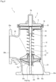
- Fig. 2 is a longitudinal sectional view of the check valve 1 in a closed state
- Fig. 3 is a longitudinal sectional view of the check valve 1 in an open state.
- a cross section including an axial center of a valve stem 7 and center lines of an inlet pipe body part 23 and an outlet pipe body part 25 will be referred to as a longitudinal cross section.
- the check valve 1 is an angle-type check valve in which an inflow direction and an outflow direction intersect with each other.
- the check valve 1 includes: the inlet pipe body part 23 which includes an inflow port 23b; the outlet pipe body part 25 which includes an outflow port 25b; a mobile body (a reciprocative body 2) which is movable (reciprocable) to a position where a flow of a fluid is stopped and a position where a flow of the fluid is allowed; and a valve body 12 which houses the reciprocative body 2.
- the reciprocative body 2 includes a valve element 6.
- the inlet pipe body part 23 is provided with a seat 23c.
- the seat 23c may be provided in the valve body 12.
- the seat 23c is arranged so as to be capable of supporting the valve element 6, and the inflow port 23b and the seat 23c are arranged parallel to each other.
- An inner wall surface 23y on an outside-corner side of the flow path FL in the inlet pipe body part 23 is formed so as to curve toward a side of the outlet pipe body part 25 as a position gets closer from the inflow port 23b to the seat 23c.
- the check valve 1 as an angle valve is configured to have a reciprocation region of the reciprocative body 2 on an extension of the inflow direction of the fluid and to cause the fluid to flow out in a direction intersecting the inflow direction across the reciprocation region of the reciprocative body 2.
- the check valve 1 according to the present embodiment is a lift check valve in which the reciprocative body 2 is linearly reciprocable in a direction which the reciprocative body 2 approaches or moves away from the seat 23c.
- the check valve 1 according to the present embodiment is to be used as a grounded foot valve and, by using the check valve 1 on a primary side of a lifting pump (not illustrated), the check valve 1 can favorably prevent water from going down in a lifting pipe due to high reliability of water stopping.
- the present invention is not limited to such a configuration and may be configured as a swing check valve, a wafer-type check valve, and the like.
- a fluid for which a back flow is regulated by the check valve 1 is a liquid such as water
- the present invention is not limited to such a configuration.
- the fluid which passes through the check valve 1 may be a gas such as air.
- inlet pipe body part 23, the outlet pipe body part 25, and the valve body 12 are formed by integral molding in the present embodiment, the present invention is not limited to such a configuration and may be configured by bonding separate elements by welding or the like.
- valve element 6 Since movement of the valve element 6 may be inhibited by pressure due to residual air in a boss 5a of a cap 3 to be described later, the valve element 6 need not necessarily be configured to become fully open insofar as a desired flowage area can be secured. While a fully open state of the valve element 6 is shown in Fig. 3 , an opening degree of the valve element 6 is to vary in accordance with a flow rate depending on a mass of the reciprocative body 2 and a restoring force of a spring body 21.
- the check valve 1 mainly includes the reciprocative body 2, the inlet pipe body part 23, the valve body 12 which houses the reciprocative body 2, a cap (the cap 3) to be attached to the valve body 12, a biasing member (the spring body 21) which biases the valve element 6 to a primary flow path side, and the outlet pipe body part 25 which is an outflow port of the fluid.
- the check valve 1 in the present specification refers to an entirety of a pipe joint which internally includes the valve element 6 and the like.
- the inlet pipe body part 23 has the inflow port 23b of a fluid as described above and a flange part 23a at an edge on a side of an inflow end part.
- An inner wall surface 23x on an inside-corner side of the flow path FL (refer to Fig. 3 ) in the inlet pipe body part 23 is arranged more inward in a radial direction than the valve element 6 as viewed from a side of the inflow port 23b.
- the inner wall surface 23y on an outside-corner side of the flow path FL in the inlet pipe body part 23 is arranged more outward in the radial direction than the valve element 6 as viewed from the side of the inflow port 23b.
- pressure loss can be reduced by guiding, from a side of the inlet pipe body part 23, a flow of a fluid from the inlet pipe body part 23 toward the outlet pipe body part 25 via the valve element 6.
- a flat mount 15 for mounting a suction tube (not illustrated) connected to a suction pump (not illustrated) is formed so as to extend upward from a top surface of the flange part 13 while protruding more outward in the radial direction than its surroundings.
- a pressure reducing port 15a which penetrates to inside on a primary flow path side (an inflow port side) of the valve body 12 is formed in the mount 15.
- a worker By actuating the suction pump and sucking in a fluid from the suction tube toward the pressure reducing port 15a, a worker can set an upstream side of the valve element 6 to negative pressure and fill the upstream side of the valve element 6 with the fluid.
- Adopting a configuration in which a pressure sensor is mounted to the pressure reducing port 15a also enables the worker to check a pressure state inside the inlet pipe body part 23 and check whether the inside of the inlet pipe body part 23 is filled with the fluid.
- the valve body 12 is a region which houses the reciprocative body 2 so as to be reciprocable and the valve body 12 according to the present embodiment is integrally formed with the inlet pipe body part 23 and the outlet pipe body part 25 by a lost wax method.
- an annular groove for mounting an upper guide member 19 is formed on an inner wall of an upper end part of the valve body 12.
- the cap 3 to be described later is removably mounted to the valve body 12 on an extension of the inflow direction (upward direction).
- the outlet pipe body part 25 includes the outflow port 25b of a fluid as described above and includes a flange part 25a at an edge on a side of an outflow end part as shown in Fig. 1 .
- the check valve 1 is fixed to piping (not illustrated) using a fastener (not illustrated) such as a bolt or a nut at the flange part 23a of the inlet pipe body part 23 and the flange part 25a of the outlet pipe body part 25 described above.
- a fastener such as a bolt or a nut at the flange part 23a of the inlet pipe body part 23 and the flange part 25a of the outlet pipe body part 25 described above.
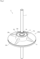
- Fig. 4 is an upper perspective view showing the reciprocative body 2 which constitutes the check valve 1
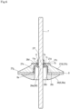
- Fig. 5 is a lower perspective view showing the reciprocative body 2
- Fig. 6 is a longitudinal sectional view of the reciprocative body 2.
- the reciprocative body 2 prevents back flow while adjusting an opening amount of the valve element 6 in accordance with a flow rate by causing the valve element 6 to approach the seat 23c and move away from the seat 23c.
- the reciprocative body 2 is configured to be movable upward and downward in the valve body 12 and, as shown in Fig. 2 , restricts a flow of a fluid when being positioned below and abutting against the seat 23c (refer to Fig. 3 ).
- the reciprocative body 2 allows the flow of the fluid and forms a flow path FL when being positioned above.
- the mobile body (reciprocative body 2) includes the valve element 6 capable of abutting against/separating from the seat 23c and the valve stem 7 which is provided so as to guide the up-down motion of the reciprocative body 2 and which is mounted so as to penetrate a center part of the valve element 6.
- the valve stem 7 is configured to come into slidable contact with a lower guide member 17, a guide adapter 18, the upper guide member 19, and a guide adapter 20 to be described later in order to prevent the reciprocative body 2 from wavering in a direction (radial direction) perpendicular to the axial direction of the valve stem 7 when the reciprocative body 2 reciprocates.
- the valve stem 7 is formed in a rod shape and extends in a reciprocation direction and is guided by the lower guide member 17 (and the guide adapter 18) to be described later and the guide adapter 20 to be described later.
- the valve stem 7 is arranged shifted to the inside-corner side of the flow path FL than a center 23v (refer to Fig. 2 ) of the inflow port 23b as viewed from the side of the inflow port 23b.
- valve stem 7 is arranged in proximity to the inner wall surface 23x on the inside-corner side than the inner wall surface 23y on the outside-corner side of the flow path FL as viewed from the side of the inflow port 23b.
- the seat 23c provided in the inlet pipe body part 23 can be arranged at a high position.
- a position of the valve element 6 fixed to the valve stem 7 is determined by a position of the valve stem 7 and a position of the seat 23c which supports the valve element 6 is determined by a position of the valve element 6.
- the inner wall surface 23x on the outside-corner side of the flow path FL in the inlet pipe body part 23 is curved toward a side of the outlet pipe body part 25 as a position gets closer from the inflow port 23b to the seat 23c. Therefore, the position of the seat 23c and a position of the lower guide member 17 which is arranged below the seat 23c are to be higher positions than in a case where the valve stem 7 is at the center 23v of the inflow port 23b.
- valve stem 7 which extends to a position that overlaps with the lower guide member 17 or to below the lower guide member 17 can be prevented from protruding from the inflow port 23b.
- a stroke amount of the reciprocative body 2 can be reduced to advance a close timing of the valve element 6 from an open state to a closed state.
- the valve stem 7 includes a screw part 7a for tightening a nut 11 to be described later, a stopper 7b which limits a downward movement of the valve element 6 to be described later, and an engaging depression 7c which an engaging projection 26e of a lower disk 26 to be described later engages with.
- the engaging depression 7c is positioned between the screw part 7a and the stopper 7b and formed with a smaller diameter than the screw part 7a and the stopper 7b.
- the valve element 6 is a primary part of the check valve 1 and is provided in a lower end part of the valve stem 7 as shown in Fig. 6 .
- valve element 6 In the closed state shown in Fig. 2 , the valve element 6 is biased by the spring body 21 and pushed against the seat 23c (refer to Fig. 3 ).
- the check valve 1 is a so-called Smolensky-type. Therefore, due to a biasing force produced by the spring body 21, the check valve 1 can quickly close the flow path by having the valve element 6 abut against the seat 23c the moment a flow of the fluid reverses to a back flow which flows from the side of the outlet pipe body part 25 to the side of the inlet pipe body part 23. Accordingly, back flow can be prevented, an occurrence of water hammer can be suppressed, and reliability of a closed state (stop ability) can be enhanced.
- the check valve 1 is not limited to a configuration in which the check valve 1 includes the spring body 21 and presses the valve element 6 against the seat 23c.
- a configuration may be adopted in which the valve element 6 is pressed against the seat 23c solely by a self-weight of the reciprocative body 2 or by the self-weight of the reciprocative body 2 and a load applied from a damper mechanism constituted of the valve stem 7 and the guide adapter 20 to be described later.
- the valve element 6 includes the lower disk 26, the upper disk 27, and a disk-shaped packing 8 (refer to Figs. 4 and 6 ) which is sandwiched between the lower disk 26 and the upper disk 27 and which adheres to the seat 23c (refer to Fig. 3 ) in a circular manner when the reciprocative body 2 shown in Fig. 2 is at a closed position.
- the worker tightens the nut 11 to the screw part 7a in a state where the lower disk 26, the packing 8, and the upper disk 27 are arranged between the stopper 7b and the screw part 7a.
- the lower disk 26, the packing 8, and the upper disk 27 are to be integrally sandwiched between a washer 11a provided between the nut 11 and the stopper 7b and the reciprocative body 2 is to be assembled together with the valve stem 7.
- At least a part (a bottom surface 26a) of a lower part of the valve element 6 (the lower disk 26) is formed in a partially spherical shape which protrudes toward the inflow port 23b.
- a depression 26b which is depressed more upward than the bottom surface 26a is formed in a central portion of the lower part of the valve element 6 (the lower disk 26).
- the depression 26b forms a space between the valve stem 7 and the lower part of the valve element 6 (the lower disk 26) and is formed so as to be capable of housing at least a part of a guide member (the guide adapter 18).
- a protrusion 26c which protrudes upward so as to penetrate into a columnar depression 27e of the upper disk 27 to be described later is formed in the lower disk 26.
- An insertion hole 26f is formed in a center portion in the radial direction of the protrusion 26c, and the engaging projection 26e which engages with the engaging depression 7c of the valve stem 7 is formed on an inner wall surface of the insertion hole 26f.
- a tubular support part 26d which extends upward is formed in an edge portion of the insertion hole 26f at a center of the protrusion 26c.
- the support part 26d is for increasing a contact area with the valve stem 7 to suitably support the valve stem 7.
- the columnar depression 26b which is depressed more upward than the bottom surface 26a on the partial sphere is formed on an inner side of the protrusion 26c. Furthermore, the bottom surface 26a on an outer side in the radial direction of the depression 26b in the valve element 6 (the lower disk 26) is formed in a partially spherical shape.
- the depression 26b enables the guide adapter 18 to be described later to be housed. As shown in Fig. 2 , the depression 26b is formed with a larger diameter than the guide adapter 18 so that a bottom surface above the depression 26b is positioned above the guide adapter 18 in a closed state of the valve.
- the side of the inflow port 23b is formed in a partially spherical shape, a decline in a speed of a fluid can be suppressed when the fluid passes the valve element 6. Therefore, the fluid can be caused to flow at a low head loss even in the lift check valve 1 in which an inflow direction to the seat 23c and a passing direction of the valve element 6 intersect with each other.
- the packing 8 is a member which stops water by being pressed so as to be sandwiched between the valve element 6 and the seat 23c in the closed state of the check valve 1 and, as shown in Fig. 6 , the packing 8 is arranged between the lower disk 26 and the upper disk 27.
- the packing 8 is formed in an annular shape including a center hole 8a which penetrates the packing 8 in a thickness direction.
- the center hole 8a is formed larger than a diameter of an outer circumferential surface of the protrusion 26c formed in the lower disk 26 in a direction perpendicular to the axial center direction of the valve stem 7.
- the center hole 8a is formed in a same or equal (including approximately equal) size to a diameter of an inner circumferential surface of the depression 27e formed in the upper disk 27.
- the packing 8 is arranged in a periphery of a lower end part of the protrusion 26c by being inserted, through the protrusion 26c of the lower disk 26, into the center hole 8a to a position abutting against a top surface in the lower disk 26 which is more outward in the radial direction than the protrusion 26c.
- the packing 8 according to the present embodiment is made of rubber, the packing 8 can stop water in a favorable manner due to high deformability which enables the packing 8 to adhere closely to the seat 23c.
- a center portion in the radial direction of the packing 8 is positioned behind the lower disk 26 in an upward view when the reciprocation direction of the reciprocative body 2 is considered an up-down direction.
- an entirety of the packing 8 is positioned behind the upper disk 27 in a downward view.
- the packing 8, and the lower disk 26 and the upper disk 27, may be additionally glued (or bonded) by an adhesive body such as an adhesive or a double-sided adhesive tape.
- the upper disk 27 mainly includes a disk-shaped flat plate part 27a, a cylindrical part 27c formed so as to protrude upward from a center part of the flat plate part 27a, and a seat surface 27d which supports a lower end part of the spring body 21 and the washer 11a of the nut 11.
- a through-hole 27f is formed at center of the seat surface 27d and configured so that the valve stem 7 can be inserted into the through-hole 27f.
- the depression 27e which houses the protrusion 26c of the lower disk 26 described above is formed on a lower surface side of the cylindrical part 27c.
- Four ribs 27b with a triangular shape in a side view are arranged at positions that deviate from each other by a central angle of 45 degrees in a plan view between the flat plate part 27a and the cylindrical part 27c.
- the ribs 27b are not formed so as to reach a peripheral edge 27g of the upper disk 27 and are connected to the flat plate part 27a.
- the upper disk 27 uniformly supports the packing 8 in a planar direction with the packing 8 between the upper disk 27 and the lower disk 26 by having a top surface (the seat surface 27d) of the upper disk 27 being pushed via the washer 11a from the nut 11 tightened to the screw part 7a.
- the lower disk 26 and the upper disk 27 are configured as an assembly of separate members.
- the packing 8 is more readily arranged between the lower disk 26 and the upper disk 27.
- the lower disk 26 and the upper disk 27 are not limited to such a configuration and when the packing 8 can be mounted to the valve element 6 by deforming the packing 8 due to the packing 8 having flexibility, the lower disk 26 and the upper disk 27 need not necessarily be constituted of separate members.
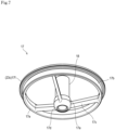
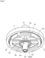
- Fig. 7 is a lower perspective view showing the lower guide member 17 and the guide adapter 18, and Fig. 8 is a lower perspective view showing a top plate part 5, the upper guide member 19, and the guide adapter 20.
- the inlet pipe body part 23 is provided with a guide member (the lower guide member 17) which guides (a lower part of) the valve stem 7.
- the lower guide member 17 may be provided in the valve body 12 instead of the inlet pipe body part 23.
- the lower guide member 17 includes a central part 17a through which the valve stem 7 is passed, an outer part 17b which is more outward in the radial direction than the central part 17a and which includes the seat 23c, and a coupling part 17c which couples the central part 17a and the outer part 17b to each other.
- the coupling part 17c according to the present embodiment includes three rods which extend in a radial direction at 120-degree central angle intervals from the central part 17a and which are connected to the outer part 17b.
- a lower end part 17d of the central part 17a is formed in a curved surface shape with a larger curvature than a region (bottom surface 26a) with a partially spherical shape of the valve element 6.
- the central part 17a has a function of guiding a movement of the reciprocative body 2 so that a lower end side of the reciprocative body 2 does not waver to a side of a radial direction of the valve stem 7 (a direction perpendicular to the axial center direction of the valve stem 7) when the reciprocative body 2 reciprocates.
- the central part 17a is formed in a thick ring shape which is larger in the up-down direction than the coupling part 17c and includes, in a central portion thereof, an insertion hole formed so as to penetrate the central part 17a in the up-down direction.
- the lower end part 17d of the central part 17a is formed in a partially spherical shape. Therefore, a fluid that flows in from the inflow port 23b below collides with the lower end part 17d and spreads outward in the radial direction, flows toward the bottom surface 26a of the lower disk 26 formed more outward in the radial direction than the central part 17a, and pushes up the bottom surface 26a.
- a lower end part of the guide adapter 18 is fitted to the central part 17a.
- the guide adapter 18 has a function of extending upward in a guide range of the central part 17a with respect to the valve stem 7 and is arranged so as to protrude above the central part 17a.
- the outer part 17b is to be fixed to the inlet pipe body part 23 and is formed in a ring shape that is thick in a height direction and thin in a thickness direction.
- a lower edge 17e of the outer part 17b is formed so as to extend more outward in the radial direction than an upper part thereof and fit into a groove formed on an inner wall surface of the inlet pipe body part 23.
- An upper edge 17f of the outer part 17b extends more outward in the radial direction than other regions (particularly, the lower edge 17e) and forms the seat 23c.
- the central part 17a and the coupling part 17c in the guide member are formed so as to be more depressed in a direction (downward) of separation from the valve element 6 than the outer part 17b.
- the coupling part 17c is extended upward while radially spreading from the central part 17a and connected to the outer part 17b. Therefore, the central part 17a and the coupling part 17c are formed so as to be depressed more downward than the outer part 17b.
- the valve body 12 is provided with the upper guide member 19 which guides an upper part of the valve stem 7.
- the upper guide member 19 includes a central part 19a, an outer part 19b which is more outward in the radial direction than the central part 19a, and a coupling part 19c which couples the central part 19a and the outer part 19b to each other.
- the coupling part 19c according to the present embodiment includes three rods which extend in a radial direction at 120-degree central angle intervals from the central part 19a and which are connected to the outer part 19b.
- Housing grooves 19d which have an inverted L shape and which are uniformly depressed inward in the radial direction are arranged at 90-degree central angle intervals on a peripheral surface (an outer wall 19e) of the outer part 19b.
- the housing grooves 19d are a region for housing projecting strips formed on an inner wall in an upper part of the valve body 12 and are formed by a vertical groove which extends in the up-down direction and a lateral groove which extends toward a left wide in a side view from an upper part of the vertical groove. Lengths of the vertical groove and the lateral groove in a peripheral direction are equal (including approximately equal) to each other and a length of the vertical groove in the up-down direction is twice a length of the lateral groove in the up-down direction.
- an engaging projection 19f which extends above other regions is formed in a portion opposing a portion where the vertical groove and the lateral groove intersect with each other.
- the engaging projection 19f has a function of fixing the upper guide member 19 to the valve body 12 by engaging with a part of the projecting stripes formed on an inner wall in an upper part of the valve body 12.
- the guide adapter 20 is fitted to the central part 17a of the upper guide member 19.
- the guide adapter 20 is erected downward (to the side of the inflow port 23b) from the upper guide member 19.
- the guide adapter 20 guides a reciprocation of an upper end side of the valve stem 7 by having an inner wall surface of a through-hole 20c which penetrates a center of the guide adapter 20 come into slidable contact with the valve stem 7 so that the reciprocative body 2 becomes reciprocable without wavering in the radial direction.
- the guide adapter 20 mainly includes a disk part 20a and a tubular part 20b which extends downward from a center of the disk part 20a.
- Four ribs 20d with a triangular shape in a side view are arranged at 45-degree center angle intervals in a bottom view between the disk part 20a and the tubular part 20b.
- the cap 3 is to be removably mounted to the valve body 12 to seal an upward side of the valve element 6.
- the cap 3 is mainly constituted of a plate-shaped top plate part 5 and the boss 5a which protrudes upward from the top plate part 5.
- the top plate part 5 includes a ferrule flange on an end edge and is stacked via a gasket 16 on a ferrule flange formed in an upper end part of the valve body 12, and is removably fastened by a ferrule 22.
- the boss 5a internally includes a hollow space and is configured to be capable of housing the valve stem 7 having moved upward.
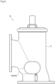
- Fig. 9 is a front view showing an outer appearance of the check valve 1X according to the second embodiment of the present invention
- Fig. 10 is a longitudinal sectional view of the check valve 1X.
- An inlet pipe body part 43 is provided with a guide member (the lower guide member 17) which guides the valve stem 7.
- a protruding part 43d which protrudes from its surroundings is formed on an outer wall surface 43z on an inside-corner side of the flow path FL (refer to Fig. 3 ).
- the protruding part 43d is formed so as to only protrude on the inside-corner side of the flow path FL (refer to Fig. 3 ) on the outer wall surface 43z in the region that supports the lower guide member 17 in the inlet pipe body part 43.
- the protruding part 43d is formed so as to protrude with respect to a virtual arc along the flow path FL on the inside-corner side of the outer wall surface 43z of the inlet pipe body part 43.
- the lower guide member 17 has been described as being provided in the inlet pipe body part 43, the lower guide member 17 is not limited to such a configuration and may be provided in the valve body 12.
- a thickness of the region that supports the guide member (the lower guide member 17) in the inlet pipe body part 43 or the valve body 12 can be prevented from becoming thin.
- valve element 6 when supported by the seat 23c can be brought close to a position of a center of the flow path FL.
- valve element 6 since a load of a fluid can act on the valve element 6 in an efficient manner, pressure loss when operating the valve element 6 can be reduced.
- Each of the various constituent elements of the check valves and the reciprocative member constituting the check valves according to the present invention need not be an individual entity.
- a plurality of constituent elements may be formed as a single member, a single constituent element may be formed by a plurality of members, a given constituent element may constitute a part of another constituent element, a part of a given constituent element and a part of another constituent element may overlap with each other, and the like.
Landscapes
- Engineering & Computer Science (AREA)
- General Engineering & Computer Science (AREA)
- Mechanical Engineering (AREA)
- Check Valves (AREA)
- Valve Housings (AREA)
- Compressor (AREA)
- Valve-Gear Or Valve Arrangements (AREA)
Abstract
Description
- The present invention relates to a check valve.
- Check valves that allow a fluid in a pipe to pass in one direction are known. There are check valves of various types that are classified according to operating modes of a valve element.
- Among such check valves, a lift check valve is structured such that a valve element linearly reciprocates in a direction which the valve element approaches or moves away from a seat and is capable of a quick closing operation. In particular, a Smolensky-type lift check valve is equipped with a spring that enables occurrences of water hammer to be suitably suppressed.
-
Patent Document 1 describes a lift check valve which includes a seat and a valve element that linearly reciprocatively swings in a direction which the valve element approaches or moves away from the seat, wherein an inflow direction of a fluid that flows to a side of the seat and an outflow direction in which the fluid passes through the valve element and flows out intersect with each other. - Patent Document 1: International Publication No.
WO 2013/180108 - However, the check valve described in
Patent Document 1 has room for improvement in terms of reducing pressure loss. - The present invention has been made in consideration of the problem described above and an object thereof is to provide a check valve capable of reducing pressure loss.
- A check valve according to the present invention is an angle-type check valve in which an inflow direction and an outflow direction intersect with each other, the check valve including: an inlet pipe body part which includes an inflow port; an outlet pipe body part which includes an outflow port; a mobile body which is movable to a position where a flow of a fluid is stopped and a position where a flow of the fluid is allowed; and a valve body which houses the mobile body, wherein insides of the inlet pipe body part, the outlet pipe body part, and the valve body are communicated to form a curved flow path from the inflow port toward the outflow port, the mobile body includes a valve element, the inlet pipe body part or the valve body is provided with a seat, the seat is arranged so as to be capable of supporting the valve element, the inflow port and the seat are arranged parallel to each other, and an inner wall surface on an outside-corner side of the flow path in the inlet pipe body part is formed so as to curve toward a side of the outlet pipe body part as a position gets closer from the inflow port to the seat.
- According to the present invention, a fluid is enabled to flow smoothly from an inlet pipe body part to an outlet pipe body part and pressure loss can be reduced.
-
-
Fig. 1 is a perspective view showing an outer appearance of a check valve according to a first embodiment of the present invention. -
Fig. 2 is a longitudinal sectional view of the check valve in a closed state. -
Fig. 3 is a longitudinal sectional view of the check valve in an open state. -
Fig. 4 is an upper perspective view showing a reciprocative body which constitutes the check valve. -
Fig. 5 is a lower perspective view showing the reciprocative body. -
Fig. 6 is a longitudinal sectional view of the reciprocative body. -
Fig. 7 is a lower perspective view showing a lower guide member and a guide adapter. -
Fig. 8 is a lower perspective view showing a top plate part, an upper guide member, and a guide adapter. -
Fig. 9 is a front view showing an outer appearance of a check valve according to a second embodiment of the present invention. -
Fig. 10 is a longitudinal sectional view of the check valve according to the second embodiment. - Hereinafter, embodiments of the present invention will be described with reference to the drawings.
- It should be noted that the embodiments described below merely represent examples for facilitating understanding of the present invention and are not intended to limit the present invention. In other words, shapes, dimensions, arrangements, and the like of members described below may be modified or improved without departing from the spirit and scope of the present invention and the present invention is intended to cover all equivalents thereof.
- Furthermore, in all of the drawings, similar constituent elements will be denoted by similar reference signs and redundant descriptions will not be repeated. While descriptions may be given in the present specification by defining up-down directions, the up-down directions are merely set for the sake of convenience for explaining correspondence relationships among the constituent elements and are not intended to limit directions during production or during use of products according to the present invention.
- First, an outline of a
check valve 1 according to a first embodiment will be described mainly with reference toFigs. 1 to 3 .Fig. 1 is a perspective view showing an outer appearance of thecheck valve 1 according to the first embodiment of the present invention,Fig. 2 is a longitudinal sectional view of thecheck valve 1 in a closed state, andFig. 3 is a longitudinal sectional view of thecheck valve 1 in an open state. - A cross section including an axial center of a
valve stem 7 and center lines of an inletpipe body part 23 and an outletpipe body part 25 will be referred to as a longitudinal cross section. - As shown in
Fig. 1 , thecheck valve 1 according to the present embodiment is an angle-type check valve in which an inflow direction and an outflow direction intersect with each other. - As shown in
Fig. 2 , thecheck valve 1 includes: the inletpipe body part 23 which includes aninflow port 23b; the outletpipe body part 25 which includes anoutflow port 25b; a mobile body (a reciprocative body 2) which is movable (reciprocable) to a position where a flow of a fluid is stopped and a position where a flow of the fluid is allowed; and avalve body 12 which houses thereciprocative body 2. - As shown in
Fig. 3 , insides of the inletpipe body part 23, the outletpipe body part 25, and thevalve body 12 are communicated to form a curved flow path FL from theinflow port 23b toward theoutflow port 25b. Thereciprocative body 2 includes avalve element 6. - The inlet
pipe body part 23 is provided with aseat 23c. Alternatively, theseat 23c may be provided in thevalve body 12. Theseat 23c is arranged so as to be capable of supporting thevalve element 6, and theinflow port 23b and theseat 23c are arranged parallel to each other. - An
inner wall surface 23y on an outside-corner side of the flow path FL in the inletpipe body part 23 is formed so as to curve toward a side of the outletpipe body part 25 as a position gets closer from theinflow port 23b to theseat 23c. - More specifically, the
check valve 1 as an angle valve according to the present embodiment is configured to have a reciprocation region of thereciprocative body 2 on an extension of the inflow direction of the fluid and to cause the fluid to flow out in a direction intersecting the inflow direction across the reciprocation region of thereciprocative body 2. - In addition, the
check valve 1 according to the present embodiment is a lift check valve in which thereciprocative body 2 is linearly reciprocable in a direction which thereciprocative body 2 approaches or moves away from theseat 23c. Thecheck valve 1 according to the present embodiment is to be used as a grounded foot valve and, by using thecheck valve 1 on a primary side of a lifting pump (not illustrated), thecheck valve 1 can favorably prevent water from going down in a lifting pipe due to high reliability of water stopping. - However, the present invention is not limited to such a configuration and may be configured as a swing check valve, a wafer-type check valve, and the like. In addition, while a fluid for which a back flow is regulated by the
check valve 1 is a liquid such as water, the present invention is not limited to such a configuration. The fluid which passes through thecheck valve 1 may be a gas such as air. - While the inlet
pipe body part 23, the outletpipe body part 25, and thevalve body 12 are formed by integral molding in the present embodiment, the present invention is not limited to such a configuration and may be configured by bonding separate elements by welding or the like. - In addition, "toward a side of the outlet
pipe body part 25" is synonymous with "to approach the outletpipe body part 25". - According to the configuration described above, due to the
inner wall surface 23y on an outside-corner side of the flow path FL in the inletpipe body part 23 being formed so as to curve toward the side of the outletpipe body part 25 as a position gets closer to theseat 23c, a fluid can be caused to flow smoothly from the inletpipe body part 23 to the outletpipe body part 25 and pressure loss can be reduced. - Since movement of the
valve element 6 may be inhibited by pressure due to residual air in aboss 5a of acap 3 to be described later, thevalve element 6 need not necessarily be configured to become fully open insofar as a desired flowage area can be secured. While a fully open state of thevalve element 6 is shown inFig. 3 , an opening degree of thevalve element 6 is to vary in accordance with a flow rate depending on a mass of thereciprocative body 2 and a restoring force of aspring body 21. - Next, a configuration of each part constituting the
check valve 1 according to the present embodiment will be described. - The
check valve 1 mainly includes thereciprocative body 2, the inletpipe body part 23, thevalve body 12 which houses thereciprocative body 2, a cap (the cap 3) to be attached to thevalve body 12, a biasing member (the spring body 21) which biases thevalve element 6 to a primary flow path side, and the outletpipe body part 25 which is an outflow port of the fluid. In other words, thecheck valve 1 in the present specification refers to an entirety of a pipe joint which internally includes thevalve element 6 and the like. - As shown in
Fig. 2 , the inletpipe body part 23 has theinflow port 23b of a fluid as described above and aflange part 23a at an edge on a side of an inflow end part. - An
inner wall surface 23x on an inside-corner side of the flow path FL (refer toFig. 3 ) in the inletpipe body part 23 is arranged more inward in a radial direction than thevalve element 6 as viewed from a side of theinflow port 23b. Theinner wall surface 23y on an outside-corner side of the flow path FL in the inletpipe body part 23 is arranged more outward in the radial direction than thevalve element 6 as viewed from the side of theinflow port 23b. - According to the configuration described above, pressure loss can be reduced by guiding, from a side of the inlet
pipe body part 23, a flow of a fluid from the inletpipe body part 23 toward the outletpipe body part 25 via thevalve element 6. - As shown in
Fig. 1 , in the inletpipe body part 23, aflat mount 15 for mounting a suction tube (not illustrated) connected to a suction pump (not illustrated) is formed so as to extend upward from a top surface of the flange part 13 while protruding more outward in the radial direction than its surroundings. Apressure reducing port 15a which penetrates to inside on a primary flow path side (an inflow port side) of thevalve body 12 is formed in themount 15. - By actuating the suction pump and sucking in a fluid from the suction tube toward the
pressure reducing port 15a, a worker can set an upstream side of thevalve element 6 to negative pressure and fill the upstream side of thevalve element 6 with the fluid. - Adopting a configuration in which a pressure sensor is mounted to the
pressure reducing port 15a also enables the worker to check a pressure state inside the inletpipe body part 23 and check whether the inside of the inletpipe body part 23 is filled with the fluid. - The
valve body 12 is a region which houses thereciprocative body 2 so as to be reciprocable and thevalve body 12 according to the present embodiment is integrally formed with the inletpipe body part 23 and the outletpipe body part 25 by a lost wax method. - As shown in
Fig. 2 , an annular groove for mounting anupper guide member 19 is formed on an inner wall of an upper end part of thevalve body 12. In addition, thecap 3 to be described later is removably mounted to thevalve body 12 on an extension of the inflow direction (upward direction). - The outlet
pipe body part 25 includes theoutflow port 25b of a fluid as described above and includes aflange part 25a at an edge on a side of an outflow end part as shown inFig. 1 . - The
check valve 1 is fixed to piping (not illustrated) using a fastener (not illustrated) such as a bolt or a nut at theflange part 23a of the inletpipe body part 23 and theflange part 25a of the outletpipe body part 25 described above. - Next, the
reciprocative body 2 will be described by mainly referring toFigs. 4 to 6 in addition toFigs. 2 and3 .Fig. 4 is an upper perspective view showing thereciprocative body 2 which constitutes thecheck valve 1,Fig. 5 is a lower perspective view showing thereciprocative body 2, andFig. 6 is a longitudinal sectional view of thereciprocative body 2. - The
reciprocative body 2 prevents back flow while adjusting an opening amount of thevalve element 6 in accordance with a flow rate by causing thevalve element 6 to approach theseat 23c and move away from theseat 23c. Thereciprocative body 2 is configured to be movable upward and downward in thevalve body 12 and, as shown inFig. 2 , restricts a flow of a fluid when being positioned below and abutting against theseat 23c (refer toFig. 3 ). In addition, as shown inFig. 3 , thereciprocative body 2 allows the flow of the fluid and forms a flow path FL when being positioned above. - The mobile body (reciprocative body 2) includes the
valve element 6 capable of abutting against/separating from theseat 23c and thevalve stem 7 which is provided so as to guide the up-down motion of thereciprocative body 2 and which is mounted so as to penetrate a center part of thevalve element 6. - The
valve stem 7 is configured to come into slidable contact with alower guide member 17, aguide adapter 18, theupper guide member 19, and aguide adapter 20 to be described later in order to prevent thereciprocative body 2 from wavering in a direction (radial direction) perpendicular to the axial direction of thevalve stem 7 when thereciprocative body 2 reciprocates. - The
valve stem 7 is formed in a rod shape and extends in a reciprocation direction and is guided by the lower guide member 17 (and the guide adapter 18) to be described later and theguide adapter 20 to be described later. Thevalve stem 7 is arranged shifted to the inside-corner side of the flow path FL than acenter 23v (refer toFig. 2 ) of theinflow port 23b as viewed from the side of theinflow port 23b. - In other words, the
valve stem 7 is arranged in proximity to theinner wall surface 23x on the inside-corner side than theinner wall surface 23y on the outside-corner side of the flow path FL as viewed from the side of theinflow port 23b. - According to the configuration described above, due to the
valve stem 7 being arranged shifted to the inside-corner side of the flow path FL than thecenter 23v of theinflow port 23b, theseat 23c provided in the inletpipe body part 23 can be arranged at a high position. - In other words, a position of the
valve element 6 fixed to thevalve stem 7 is determined by a position of thevalve stem 7 and a position of theseat 23c which supports thevalve element 6 is determined by a position of thevalve element 6. - In addition, as described above, the
inner wall surface 23x on the outside-corner side of the flow path FL in the inletpipe body part 23 is curved toward a side of the outletpipe body part 25 as a position gets closer from theinflow port 23b to theseat 23c. Therefore, the position of theseat 23c and a position of thelower guide member 17 which is arranged below theseat 23c are to be higher positions than in a case where thevalve stem 7 is at thecenter 23v of theinflow port 23b. - Therefore, the
valve stem 7 which extends to a position that overlaps with thelower guide member 17 or to below thelower guide member 17 can be prevented from protruding from theinflow port 23b. - In addition, a stroke amount of the
reciprocative body 2 can be reduced to advance a close timing of thevalve element 6 from an open state to a closed state. - The
valve stem 7 includes ascrew part 7a for tightening anut 11 to be described later, astopper 7b which limits a downward movement of thevalve element 6 to be described later, and an engagingdepression 7c which an engagingprojection 26e of alower disk 26 to be described later engages with. - The engaging
depression 7c is positioned between thescrew part 7a and thestopper 7b and formed with a smaller diameter than thescrew part 7a and thestopper 7b. - The
spring body 21 mounted to a periphery of thevalve stem 7 elastically biases a top surface (seat surface 27d) of the valve element 6 (upper disk 27) in both a closed state shown inFig. 2 and an open state shown inFig. 3 . - The
valve element 6 is a primary part of thecheck valve 1 and is provided in a lower end part of thevalve stem 7 as shown inFig. 6 . - In the closed state shown in
Fig. 2 , thevalve element 6 is biased by thespring body 21 and pushed against theseat 23c (refer toFig. 3 ). - In other words, the
check valve 1 according to the present embodiment is a so-called Smolensky-type. Therefore, due to a biasing force produced by thespring body 21, thecheck valve 1 can quickly close the flow path by having thevalve element 6 abut against theseat 23c the moment a flow of the fluid reverses to a back flow which flows from the side of the outletpipe body part 25 to the side of the inletpipe body part 23. Accordingly, back flow can be prevented, an occurrence of water hammer can be suppressed, and reliability of a closed state (stop ability) can be enhanced. - However, the
check valve 1 is not limited to a configuration in which thecheck valve 1 includes thespring body 21 and presses thevalve element 6 against theseat 23c. For example, a configuration may be adopted in which thevalve element 6 is pressed against theseat 23c solely by a self-weight of thereciprocative body 2 or by the self-weight of thereciprocative body 2 and a load applied from a damper mechanism constituted of thevalve stem 7 and theguide adapter 20 to be described later. - The
valve element 6 includes thelower disk 26, theupper disk 27, and a disk-shaped packing 8 (refer toFigs. 4 and6 ) which is sandwiched between thelower disk 26 and theupper disk 27 and which adheres to theseat 23c (refer toFig. 3 ) in a circular manner when thereciprocative body 2 shown inFig. 2 is at a closed position. - The worker tightens the
nut 11 to thescrew part 7a in a state where thelower disk 26, thepacking 8, and theupper disk 27 are arranged between thestopper 7b and thescrew part 7a. - As a result, the
lower disk 26, thepacking 8, and theupper disk 27 are to be integrally sandwiched between awasher 11a provided between thenut 11 and thestopper 7b and thereciprocative body 2 is to be assembled together with thevalve stem 7. - At least a part (a
bottom surface 26a) of a lower part of the valve element 6 (the lower disk 26) is formed in a partially spherical shape which protrudes toward theinflow port 23b. - A
depression 26b which is depressed more upward than thebottom surface 26a is formed in a central portion of the lower part of the valve element 6 (the lower disk 26). Thedepression 26b forms a space between thevalve stem 7 and the lower part of the valve element 6 (the lower disk 26) and is formed so as to be capable of housing at least a part of a guide member (the guide adapter 18). - More specifically, a
protrusion 26c which protrudes upward so as to penetrate into acolumnar depression 27e of theupper disk 27 to be described later is formed in thelower disk 26. Aninsertion hole 26f is formed in a center portion in the radial direction of theprotrusion 26c, and the engagingprojection 26e which engages with the engagingdepression 7c of thevalve stem 7 is formed on an inner wall surface of theinsertion hole 26f. - In addition, a
tubular support part 26d which extends upward is formed in an edge portion of theinsertion hole 26f at a center of theprotrusion 26c. Thesupport part 26d is for increasing a contact area with thevalve stem 7 to suitably support thevalve stem 7. - The
columnar depression 26b which is depressed more upward than thebottom surface 26a on the partial sphere is formed on an inner side of theprotrusion 26c. Furthermore, thebottom surface 26a on an outer side in the radial direction of thedepression 26b in the valve element 6 (the lower disk 26) is formed in a partially spherical shape. - The
depression 26b enables theguide adapter 18 to be described later to be housed. As shown inFig. 2 , thedepression 26b is formed with a larger diameter than theguide adapter 18 so that a bottom surface above thedepression 26b is positioned above theguide adapter 18 in a closed state of the valve. - Due to the
depression 26b being formed in this manner, interference (abutting) of thevalve element 6 and theguide adapter 18 can be avoided and thelower guide member 17 to be described later including theseat 23c can be arranged at a high position. - As described above, since the side of the
inflow port 23b is formed in a partially spherical shape, a decline in a speed of a fluid can be suppressed when the fluid passes thevalve element 6. Therefore, the fluid can be caused to flow at a low head loss even in thelift check valve 1 in which an inflow direction to theseat 23c and a passing direction of thevalve element 6 intersect with each other. - The
packing 8 is a member which stops water by being pressed so as to be sandwiched between thevalve element 6 and theseat 23c in the closed state of thecheck valve 1 and, as shown inFig. 6 , thepacking 8 is arranged between thelower disk 26 and theupper disk 27. - The
packing 8 is formed in an annular shape including acenter hole 8a which penetrates the packing 8 in a thickness direction. Thecenter hole 8a is formed larger than a diameter of an outer circumferential surface of theprotrusion 26c formed in thelower disk 26 in a direction perpendicular to the axial center direction of thevalve stem 7. In addition, thecenter hole 8a is formed in a same or equal (including approximately equal) size to a diameter of an inner circumferential surface of thedepression 27e formed in theupper disk 27. - The
packing 8 is arranged in a periphery of a lower end part of theprotrusion 26c by being inserted, through theprotrusion 26c of thelower disk 26, into thecenter hole 8a to a position abutting against a top surface in thelower disk 26 which is more outward in the radial direction than theprotrusion 26c. - In particular, since the packing 8 according to the present embodiment is made of rubber, the packing 8 can stop water in a favorable manner due to high deformability which enables the packing 8 to adhere closely to the
seat 23c. - A center portion in the radial direction of the
packing 8 is positioned behind thelower disk 26 in an upward view when the reciprocation direction of thereciprocative body 2 is considered an up-down direction. On the other hand, an entirety of thepacking 8 is positioned behind theupper disk 27 in a downward view. - The
packing 8, and thelower disk 26 and theupper disk 27, may be additionally glued (or bonded) by an adhesive body such as an adhesive or a double-sided adhesive tape. - As shown in
Fig. 4 , theupper disk 27 mainly includes a disk-shapedflat plate part 27a, acylindrical part 27c formed so as to protrude upward from a center part of theflat plate part 27a, and aseat surface 27d which supports a lower end part of thespring body 21 and thewasher 11a of thenut 11. - A through-
hole 27f is formed at center of theseat surface 27d and configured so that thevalve stem 7 can be inserted into the through-hole 27f. Thedepression 27e which houses theprotrusion 26c of thelower disk 26 described above is formed on a lower surface side of thecylindrical part 27c. Fourribs 27b with a triangular shape in a side view are arranged at positions that deviate from each other by a central angle of 45 degrees in a plan view between theflat plate part 27a and thecylindrical part 27c. Theribs 27b are not formed so as to reach aperipheral edge 27g of theupper disk 27 and are connected to theflat plate part 27a. - The
upper disk 27 uniformly supports the packing 8 in a planar direction with the packing 8 between theupper disk 27 and thelower disk 26 by having a top surface (theseat surface 27d) of theupper disk 27 being pushed via thewasher 11a from thenut 11 tightened to thescrew part 7a. - As described above, the
lower disk 26 and theupper disk 27 are configured as an assembly of separate members. By configuring thelower disk 26 and theupper disk 27 as an assembly of separate members as described above, thepacking 8 is more readily arranged between thelower disk 26 and theupper disk 27. - However, the
lower disk 26 and theupper disk 27 are not limited to such a configuration and when thepacking 8 can be mounted to thevalve element 6 by deforming thepacking 8 due to thepacking 8 having flexibility, thelower disk 26 and theupper disk 27 need not necessarily be constituted of separate members. - Next, the guide members which guide reciprocation of the
reciprocative body 2 will be described by mainly referring toFigs. 7 and8 in addition toFigs. 2 and3 .Fig. 7 is a lower perspective view showing thelower guide member 17 and theguide adapter 18, andFig. 8 is a lower perspective view showing atop plate part 5, theupper guide member 19, and theguide adapter 20. - The inlet
pipe body part 23 is provided with a guide member (the lower guide member 17) which guides (a lower part of) thevalve stem 7. Note that thelower guide member 17 may be provided in thevalve body 12 instead of the inletpipe body part 23. - As shown in
Fig. 7 , thelower guide member 17 includes acentral part 17a through which thevalve stem 7 is passed, anouter part 17b which is more outward in the radial direction than thecentral part 17a and which includes theseat 23c, and acoupling part 17c which couples thecentral part 17a and theouter part 17b to each other. Thecoupling part 17c according to the present embodiment includes three rods which extend in a radial direction at 120-degree central angle intervals from thecentral part 17a and which are connected to theouter part 17b. - A
lower end part 17d of thecentral part 17a is formed in a curved surface shape with a larger curvature than a region (bottom surface 26a) with a partially spherical shape of thevalve element 6. - More specifically, the
central part 17a has a function of guiding a movement of thereciprocative body 2 so that a lower end side of thereciprocative body 2 does not waver to a side of a radial direction of the valve stem 7 (a direction perpendicular to the axial center direction of the valve stem 7) when thereciprocative body 2 reciprocates. Thecentral part 17a is formed in a thick ring shape which is larger in the up-down direction than thecoupling part 17c and includes, in a central portion thereof, an insertion hole formed so as to penetrate thecentral part 17a in the up-down direction. - As described above, the
lower end part 17d of thecentral part 17a is formed in a partially spherical shape. Therefore, a fluid that flows in from theinflow port 23b below collides with thelower end part 17d and spreads outward in the radial direction, flows toward thebottom surface 26a of thelower disk 26 formed more outward in the radial direction than thecentral part 17a, and pushes up thebottom surface 26a. - A lower end part of the
guide adapter 18 is fitted to thecentral part 17a. Theguide adapter 18 has a function of extending upward in a guide range of thecentral part 17a with respect to thevalve stem 7 and is arranged so as to protrude above thecentral part 17a. - According to the configuration described above, due to the curvature of the
lower end part 17d of thecentral part 17a being larger than a curvature of thevalve element 6 that is pushed up by the fluid, pressure loss with respect to the fluid that flows in from theinflow port 23b can be reduced. - The
outer part 17b is to be fixed to the inletpipe body part 23 and is formed in a ring shape that is thick in a height direction and thin in a thickness direction. - A
lower edge 17e of theouter part 17b is formed so as to extend more outward in the radial direction than an upper part thereof and fit into a groove formed on an inner wall surface of the inletpipe body part 23. Anupper edge 17f of theouter part 17b extends more outward in the radial direction than other regions (particularly, thelower edge 17e) and forms theseat 23c. - In other words, among a fluid that flows in from the
inflow port 23b, the fluid abutting against thelower edge 17e of thecentral part 17a of thelower guide member 17 collides with thelower edge 17e and spreads, and collides with thebottom surface 26a of thevalve element 6 and pushes up thevalve element 6. - The
central part 17a and thecoupling part 17c in the guide member (the lower guide member 17) are formed so as to be more depressed in a direction (downward) of separation from thevalve element 6 than theouter part 17b. - In other words, the
coupling part 17c is extended upward while radially spreading from thecentral part 17a and connected to theouter part 17b. Therefore, thecentral part 17a and thecoupling part 17c are formed so as to be depressed more downward than theouter part 17b. - According to such a configuration, even when the
bottom surface 26a which constitutes a part of thevalve element 6 that abuts against theseat 23c on the top surface of theouter part 17b bulges downward, (thebottom surface 26a of) thevalve element 6 can be prevented from interfering with (abutting against) thecentral part 17a. - The
valve body 12 is provided with theupper guide member 19 which guides an upper part of thevalve stem 7. - The
upper guide member 19 includes acentral part 19a, anouter part 19b which is more outward in the radial direction than thecentral part 19a, and acoupling part 19c which couples thecentral part 19a and theouter part 19b to each other. Thecoupling part 19c according to the present embodiment includes three rods which extend in a radial direction at 120-degree central angle intervals from thecentral part 19a and which are connected to theouter part 19b. -
Housing grooves 19d which have an inverted L shape and which are uniformly depressed inward in the radial direction are arranged at 90-degree central angle intervals on a peripheral surface (anouter wall 19e) of theouter part 19b. Thehousing grooves 19d are a region for housing projecting strips formed on an inner wall in an upper part of thevalve body 12 and are formed by a vertical groove which extends in the up-down direction and a lateral groove which extends toward a left wide in a side view from an upper part of the vertical groove. Lengths of the vertical groove and the lateral groove in a peripheral direction are equal (including approximately equal) to each other and a length of the vertical groove in the up-down direction is twice a length of the lateral groove in the up-down direction. Among theouter wall 19e, an engagingprojection 19f which extends above other regions is formed in a portion opposing a portion where the vertical groove and the lateral groove intersect with each other. - The engaging
projection 19f has a function of fixing theupper guide member 19 to thevalve body 12 by engaging with a part of the projecting stripes formed on an inner wall in an upper part of thevalve body 12. - An upper end part of the
guide adapter 20 is fitted to thecentral part 17a of theupper guide member 19. Theguide adapter 20 is erected downward (to the side of theinflow port 23b) from theupper guide member 19. - The
guide adapter 20 guides a reciprocation of an upper end side of thevalve stem 7 by having an inner wall surface of a through-hole 20c which penetrates a center of theguide adapter 20 come into slidable contact with thevalve stem 7 so that thereciprocative body 2 becomes reciprocable without wavering in the radial direction. - The
guide adapter 20 mainly includes adisk part 20a and atubular part 20b which extends downward from a center of thedisk part 20a. Fourribs 20d with a triangular shape in a side view are arranged at 45-degree center angle intervals in a bottom view between thedisk part 20a and thetubular part 20b. - As shown in
Fig. 2 , thecap 3 is to be removably mounted to thevalve body 12 to seal an upward side of thevalve element 6. As shown inFig. 2 , thecap 3 is mainly constituted of a plate-shapedtop plate part 5 and theboss 5a which protrudes upward from thetop plate part 5. - The
top plate part 5 includes a ferrule flange on an end edge and is stacked via agasket 16 on a ferrule flange formed in an upper end part of thevalve body 12, and is removably fastened by aferrule 22. - The
boss 5a internally includes a hollow space and is configured to be capable of housing thevalve stem 7 having moved upward. - Next, a
check valve 1X according to a second embodiment will be described with reference toFig. 9 andFig. 10 . -
Fig. 9 is a front view showing an outer appearance of thecheck valve 1X according to the second embodiment of the present invention, andFig. 10 is a longitudinal sectional view of thecheck valve 1X. - An inlet
pipe body part 43 is provided with a guide member (the lower guide member 17) which guides thevalve stem 7. In a region that supports thelower guide member 17 in the inletpipe body part 43, a protrudingpart 43d which protrudes from its surroundings is formed on anouter wall surface 43z on an inside-corner side of the flow path FL (refer toFig. 3 ). - Specifically, the protruding
part 43d is formed so as to only protrude on the inside-corner side of the flow path FL (refer toFig. 3 ) on theouter wall surface 43z in the region that supports thelower guide member 17 in the inletpipe body part 43. In addition, as shown in the longitudinal cross section inFig. 10 , the protrudingpart 43d is formed so as to protrude with respect to a virtual arc along the flow path FL on the inside-corner side of theouter wall surface 43z of the inletpipe body part 43. - While the
lower guide member 17 has been described as being provided in the inletpipe body part 43, thelower guide member 17 is not limited to such a configuration and may be provided in thevalve body 12. - According to the configuration described above, a thickness of the region that supports the guide member (the lower guide member 17) in the inlet
pipe body part 43 or thevalve body 12 can be prevented from becoming thin. - Therefore, by lowering a position in the up-down direction to be a start position of separation by the
valve element 6 from theseat 23c which is the top surface of thelower guide member 17, thevalve element 6 when supported by theseat 23c can be brought close to a position of a center of the flow path FL. - In addition, since a load of a fluid can act on the
valve element 6 in an efficient manner, pressure loss when operating thevalve element 6 can be reduced. - While respective embodiments have been described above with reference to the drawings, the embodiments are illustrative only and various configurations other than those described above can also be adopted.
- Each of the various constituent elements of the check valves and the reciprocative member constituting the check valves according to the present invention need not be an individual entity. A plurality of constituent elements may be formed as a single member, a single constituent element may be formed by a plurality of members, a given constituent element may constitute a part of another constituent element, a part of a given constituent element and a part of another constituent element may overlap with each other, and the like.
- The present embodiments cover the following technical ideas.
- (1) An angle-type check valve in which an inflow direction and an outflow direction intersect with each other, the check valve including:
- an inlet pipe body part which includes an inflow port;
- an outlet pipe body part which includes an outflow port;
- a mobile body which is movable to a position where a flow of a fluid is stopped and a position where a flow of the fluid is allowed; and
- a valve body which houses the mobile body, wherein
- insides of the inlet pipe body part, the outlet pipe body part, and the valve body are communicated to form a curved flow path from the inflow port toward the outflow port,
- the mobile body includes a valve element,
- the inlet pipe body part or the valve body is provided with a seat,
- the seat is arranged so as to be capable of supporting the valve element,
- the inflow port and the seat are arranged parallel to each other, and
- an inner wall surface on an outside-corner side of the flow path in the inlet pipe body part is formed so as to curve toward a side of the outlet pipe body part as a position gets closer from the inflow port to the seat.
- (2) The check valve according to (1), wherein
- the mobile body further includes a valve stem, and
- the valve stem is arranged shifted to an inside-corner side of the flow path than a center of the inflow port as viewed from a side of the inflow port.
- (3) The check valve according to (1) or (2), wherein
- an inner wall surface on an inside-corner side of the flow path in the inlet pipe body part is arranged more inward in a radial direction than the valve element as viewed from a side of the inflow port, and
- the inner wall surface on the outside-corner side of the flow path in the inlet pipe body part is arranged more outward in the radial direction than the valve element as viewed from the side of the inflow port.
- (4) The check valve according to any one of (1) to (3), wherein
- the mobile body further includes a valve stem,
- at least a part of a lower part of the valve element is formed in a partially spherical shape which protrudes toward the inflow port,
- the inlet pipe body part or the valve body is provided with a guide member which guides the valve stem,
- the guide member includes a central part through which the valve stem is passed, an outer part which is more outward in the radial direction than the central part and which includes the seat, and a coupling part which couples the central part and the outer part to each other, and
- a lower end part of the central part is formed in a curved surface shape with a larger curvature than a region with a partially spherical shape of the valve element.
- (5) The check valve according to (4), wherein the central part and the coupling part in the guide member are formed more depressed in a direction of separation from the valve element than the outer part.
- (6) The check valve according to any one of (1) to (5), wherein
- the mobile body further includes a valve stem,
- the inlet pipe body part or the valve body is provided with a guide member which guides the valve stem,
- a depression which is depressed upward is formed in a central portion of a lower part of the valve element, and
- the depression forms a space between the valve stem and the lower part of the valve element and is formed so as to be capable of housing at least a part of the guide member.
- (7) The check valve according to any one of (1) to (6), wherein
- the mobile body further includes a valve stem,
- the inlet pipe body part or the valve body is provided with a guide member which guides the valve stem, and
- in a region that supports the guide member in the inlet pipe body part or the valve body, a protruding part which protrudes from its surroundings is formed on an outer wall surface on an inside-corner side of the flow path.
- The present application claims priority on the basis of
Japanese Patent Application No. 2021-39670 filed on March 11, 2021 Japanese Patent Application No. 2022-35357 filed on March 8, 2022 -
- 1, 1X
- check valve
- 2
- reciprocative body (mobile body)
- 3
- cap
- 5
- top plate part
5a boss - 6
- valve element
- 7
- valve stem
7a screw part
7b stopper
7c engaging depression - 8
- packing
8a center hole - 11
- nut
11a washer - 12
- valve body
- 13, 14
- flange part
- 15
- mount
15a pressure reducing port - 16
- gasket
- 17
- lower guide member (guide member)
17a central part
17b outer part
17c coupling part
17d lower end part
17e lower edge
17f upper edge - 18
- guide adapter (guide member)
- 19
- upper guide member (guide member)
19a central part
19b outer part
19c coupling part
19d housing groove
19e outer wall
19f engaging projection - 20
- guide adapter (guide member)
20a disk part
20b tubular part
20c through-hole
20d rib - 21
- spring body
- 22
- ferrule
- 23
- inlet pipe body part
23a flange part
23b inflow port
23c seat
23v center
23x, 23y inner wall surface - 25
- outlet pipe body part
25a flange part
25b outflow port - 26
- lower disk
26a bottom surface
26b depression
26c protrusion
26d support part
26e engaging projection
26f insertion hole - 27
- upper disk
27a flat plate part
27b rib
27c cylindrical part
27d seat surface
27e depression
27f through-hole
27g peripheral edge - 43
- inlet pipe body part
43d protruding part
43z outer wall surface - FL
- flow path
Claims (7)
- An angle-type check valve in which an inflow direction and an outflow direction intersect with each other, the check valve comprising:an inlet pipe body part which includes an inflow port;an outlet pipe body part which includes an outflow port;a mobile body which is movable to a position where a flow of a fluid is stopped and a position where a flow of the fluid is allowed; anda valve body which houses the mobile body, whereininsides of the inlet pipe body part, the outlet pipe body part, and the valve body are communicated to form a curved flow path from the inflow port toward the outflow port,the mobile body includes a valve element,the inlet pipe body part or the valve body is provided with a seat,the seat is arranged so as to be capable of supporting the valve element,the inflow port and the seat are arranged parallel to each other, andan inner wall surface on an outside-corner side of the flow path in the inlet pipe body part is formed so as to curve toward a side of the outlet pipe body part as a position gets closer from the inflow port to the seat.
- The check valve according to claim 1, whereinthe mobile body further includes a valve stem, andthe valve stem is arranged shifted to an inside-corner side of the flow path than a center of the inflow port as viewed from a side of the inflow port.
- The check valve according to claim 1 or 2, whereinan inner wall surface on an inside-corner side of the flow path in the inlet pipe body part is arranged more inward in a radial direction than the valve element as viewed from a side of the inflow port, andthe inner wall surface on the outside-corner side of the flow path in the inlet pipe body part is arranged more outward in the radial direction than the valve element as viewed from the side of the inflow port.
- The check valve according to any one of claims 1 to 3, whereinthe mobile body further includes a valve stem,at least a part of a lower part of the valve element is formed in a partially spherical shape which protrudes toward the inflow port,the inlet pipe body part or the valve body is provided with a guide member which guides the valve stem,the guide member includes a central part through which the valve stem is passed, an outer part which is more outward in the radial direction than the central part and which includes the seat, and a coupling part which couples the central part and the outer part to each other, anda lower end part of the central part is formed in a curved surface shape with a larger curvature than a region with a partially spherical shape of the valve element.
- The check valve according to claim 4, wherein the central part and the coupling part in the guide member are formed more depressed in a direction of separation from the valve element than the outer part.
- The check valve according to any one of claims 1 to 5, whereinthe mobile body further includes a valve stem,the inlet pipe body part or the valve body is provided with a guide member which guides the valve stem,a depression which is depressed upward is formed in a central portion of a lower part of the valve element, andthe depression forms a space between the valve stem and the lower part of the valve element and is formed so as to be capable of housing at least a part of the guide member.
- The check valve according to any one of claims 1 to 6, whereinthe mobile body further includes a valve stem,the inlet pipe body part or the valve body is provided with a guide member which guides the valve stem, andin a region that supports the guide member in the inlet pipe body part or the valve body, a protruding part which protrudes from its surroundings is formed on an outer wall surface on an inside-corner side of the flow path.
Applications Claiming Priority (3)
| Application Number | Priority Date | Filing Date | Title |
|---|---|---|---|
| JP2021039670 | 2021-03-11 | ||
| JP2022035357 | 2022-03-08 | ||
| PCT/JP2022/010289 WO2022191239A1 (en) | 2021-03-11 | 2022-03-09 | Check valve |
Publications (2)
| Publication Number | Publication Date |
|---|---|
| EP4306830A1 true EP4306830A1 (en) | 2024-01-17 |
| EP4306830A4 EP4306830A4 (en) | 2024-09-11 |
Family
ID=83226811
Family Applications (1)
| Application Number | Title | Priority Date | Filing Date |
|---|---|---|---|
| EP22767193.0A Pending EP4306830A4 (en) | 2021-03-11 | 2022-03-09 | Check valve |
Country Status (8)
| Country | Link |
|---|---|
| US (1) | US12292124B2 (en) |
| EP (1) | EP4306830A4 (en) |
| JP (1) | JP7557610B2 (en) |
| KR (1) | KR102926927B1 (en) |
| CA (1) | CA3213154A1 (en) |
| MX (1) | MX2023010277A (en) |
| TW (1) | TWI812060B (en) |
| WO (1) | WO2022191239A1 (en) |
Families Citing this family (3)
| Publication number | Priority date | Publication date | Assignee | Title |
|---|---|---|---|---|
| JP1727449S (en) * | 2022-03-08 | 2022-10-14 | ||
| JP2024104458A (en) * | 2023-01-24 | 2024-08-05 | 日本サーモスタット株式会社 | Valve mechanism |
| WO2025203242A1 (en) * | 2024-03-26 | 2025-10-02 | 株式会社イシザキ | Check valve |
Family Cites Families (13)
| Publication number | Priority date | Publication date | Assignee | Title |
|---|---|---|---|---|
| US2026110A (en) | 1934-08-24 | 1935-12-31 | Aw Wheaton Brass Works | Self-closing faucet |
| US2271497A (en) * | 1941-02-04 | 1942-01-27 | Kenyon Instr Co Inc | Pressure relief check valve |
| US2516247A (en) | 1949-02-08 | 1950-07-25 | Sadye Florence Gelb | Nonreturn flow valve |
| US3542332A (en) * | 1968-11-22 | 1970-11-24 | Alain A Chevalier | Air operated poppet seat valve |
| JP2007024241A (en) | 2005-07-20 | 2007-02-01 | Denso Corp | Fluid control valve |
| JP5331831B2 (en) | 2011-01-31 | 2013-10-30 | Ckd株式会社 | Fluid control valve |
| ES2716856T3 (en) | 2012-05-31 | 2019-06-17 | Ishizaki Corp | Check valve and hot water system |
| KR101216035B1 (en) | 2012-06-08 | 2012-12-27 | 주식회사 에쓰브이씨 | Multi-functional check valve in angled type |
| JP2015094275A (en) | 2013-11-12 | 2015-05-18 | 愛三工業株式会社 | Exhaust gas recirculation valve |
| JP6744137B2 (en) | 2016-06-07 | 2020-08-19 | 日本サーモスタット株式会社 | Thermostat device |
| KR102151431B1 (en) | 2019-06-28 | 2020-09-03 | (주)두쿰 | Check valve capable of assembling |
| JP7304778B2 (en) | 2019-09-05 | 2023-07-07 | 株式会社日立製作所 | Material property prediction system and information processing method |
| JP2022035357A (en) | 2020-08-20 | 2022-03-04 | 株式会社空環工房 | Content provision apparatus, content provision system, content provision program, and content provision method |
-
2022
- 2022-03-09 KR KR1020237026139A patent/KR102926927B1/en active Active
- 2022-03-09 US US18/278,668 patent/US12292124B2/en active Active
- 2022-03-09 WO PCT/JP2022/010289 patent/WO2022191239A1/en not_active Ceased
- 2022-03-09 JP JP2023505607A patent/JP7557610B2/en active Active
- 2022-03-09 CA CA3213154A patent/CA3213154A1/en active Pending
- 2022-03-09 MX MX2023010277A patent/MX2023010277A/en unknown
- 2022-03-09 EP EP22767193.0A patent/EP4306830A4/en active Pending
- 2022-03-11 TW TW111108989A patent/TWI812060B/en active
Also Published As
| Publication number | Publication date |
|---|---|
| US12292124B2 (en) | 2025-05-06 |
| US20240133474A1 (en) | 2024-04-25 |
| US20240229949A9 (en) | 2024-07-11 |
| JPWO2022191239A1 (en) | 2022-09-15 |
| TW202242288A (en) | 2022-11-01 |
| JP7557610B2 (en) | 2024-09-27 |
| WO2022191239A1 (en) | 2022-09-15 |
| KR102926927B1 (en) | 2026-02-11 |
| KR20230122680A (en) | 2023-08-22 |
| EP4306830A4 (en) | 2024-09-11 |
| TWI812060B (en) | 2023-08-11 |
| MX2023010277A (en) | 2023-09-11 |
| CA3213154A1 (en) | 2022-09-15 |
Similar Documents
| Publication | Publication Date | Title |
|---|---|---|
| EP4306830A1 (en) | Check valve | |
| CN110832238B (en) | Check valves and reciprocating bodies for check valves | |
| US8360283B1 (en) | Liquid foaming pump | |
| CN101102959A (en) | Flow control element and dispensing structure comprising same | |
| CN102015483A (en) | Dispensing valve assembly | |
| CN106573709A (en) | Cap | |
| CA3097290C (en) | Check valve | |
| US20240052933A1 (en) | Valve, fluid control device, pressurizing device, and sphygmomanometer | |
| JP2023036891A (en) | Metering pumps and metering devices for metering devices | |
| EP3792532A1 (en) | Gate valve | |
| US8141585B2 (en) | Rocker type diaphragm valve | |
| JP2009529634A (en) | Valve with repulsive diaphragm | |
| US20090014077A1 (en) | One piece double membrane diaphragm valve | |
| JPH11280927A (en) | Check valve | |
| CN117015673A (en) | Check valve | |
| JP2019120318A (en) | Valve mechanism | |
| JP2024033737A (en) | foam dispenser | |
| JP7141322B2 (en) | hydraulic system | |
| JP2005201278A (en) | Diaphragm pump |
Legal Events
| Date | Code | Title | Description |
|---|---|---|---|
| STAA | Information on the status of an ep patent application or granted ep patent |
Free format text: STATUS: THE INTERNATIONAL PUBLICATION HAS BEEN MADE |
|
| PUAI | Public reference made under article 153(3) epc to a published international application that has entered the european phase |
Free format text: ORIGINAL CODE: 0009012 |
|
| STAA | Information on the status of an ep patent application or granted ep patent |
Free format text: STATUS: REQUEST FOR EXAMINATION WAS MADE |
|
| 17P | Request for examination filed |
Effective date: 20230919 |
|
| AK | Designated contracting states |
Kind code of ref document: A1 Designated state(s): AL AT BE BG CH CY CZ DE DK EE ES FI FR GB GR HR HU IE IS IT LI LT LU LV MC MK MT NL NO PL PT RO RS SE SI SK SM TR |
|
| DAV | Request for validation of the european patent (deleted) | ||
| DAX | Request for extension of the european patent (deleted) | ||
| A4 | Supplementary search report drawn up and despatched |
Effective date: 20240813 |
|
| RIC1 | Information provided on ipc code assigned before grant |
Ipc: F16K 27/02 20060101ALI20240807BHEP Ipc: F16K 15/06 20060101AFI20240807BHEP |